Embed Size (px)
Citation preview
f720>(07)157
I v.7vpt.3_;
SISSJI'o
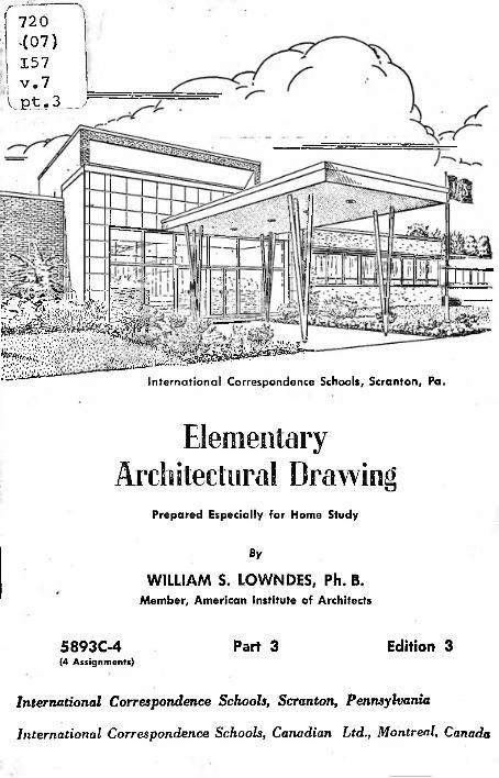
International Correspondence Schools, Scranton, Pa.
Elementary
Architectural DrawingPrepared Especially for Home Study
By
WILLIAM S. LOWNDES, Ph. B.Member, American Institute of Architects
Edition 3Part 35893C-4(4 Assignments)
International Correspondence Schools, Scranton, Pennsylvania
International Correspondence Schools, Canadian Ltd., Montreal, Canada
ELEMENTARY
ARCHITECTURAL DRAWING
v'? Pajrt 3Most careers are made or marred in the hours after supper.
—C. R. Lawton
* *
Every time you sit down after supper for your solitary struggle with your assignments, be cheered by the certainty that every hour adds another brick to the solid structure of a successful career.
By
WILLIAM S. LOWNDES, Ph. B.Member, American Institute of Architects2
Serial 5893C4
i;Copyright © 1958, 1951, by INTERNATIONAL TEXTBOOK COMPANY
Copyright in Great Britain. All rights reserved Printed in United States of America
!
International Correspondence Schoolsvr rICS Scranton, Pennsylvania /Inter national Correspondence Schools Canadian, Ltd.
Montreal, Canada
120Col)U"\A. Elementary
Architectural DrawingPart 3
DRAWING EXERCISES
ISOMETRIC DRAWING
What This Text Covers . . .
Pages 1 to 61. Isometric DrawingGeneral instructions are given for preparing the four exercises described in this text. The first drawings are in isometric. These drawings start with simple objects and gradually become more complex.
1. Introduction.—The work in Elementary Architectural Drawing, Part 3, is similar to that required in Part 2. The Exercises are to be drawn on sheets of transparent bond paper, 10" X 13J" in size. A cutting line is to be drawn around the edge of the sheet enclosing a rectangle 9£" X 12J" in size. Border lines are to be drawn § inch in from the cutting lines. Inside the border lines a space 8£" X 10§" is to be used for the drawings. Each exercise is one assignment; all the sheets in that Exercise must be sent together.
The drawing work required for this text is as follows: Exercise I; Sheets I, II, and III Exercise II; Sheets I and II Exercise III; Sheets I, II, and III Exercise IV; Sheet I
All drawings are to be carefully made in lead pencil. All lettering, including titles and the student's class letters and number, is to be drawn. Show the construction lines, all the given lines, and all the required lines as shown in the exercise in the text. With the exception of Exercise III, Sheet III dimensions need not be included. Your drawings should be carefully inspected and compared with the models in the text. When no errors can be discovered, the drawings may be submitted in pencil. Complete all the sheets of each exercise before sending them in for correction. Drawings are to be folded and forwarded to the Schools in envelopes.
The student is expected to obtain two things from the study of this text. One is a knowledge of the subjects of Isometric, Oblique, and Projection Drawing. The second is skill in draw-
i:
Pages 7 to 8Differences between oblique and isometric drawings are explained. A characteristic of oblique drawing is that it shows the true profile of the object. You will be interested in the oblique drawings of architectural moldings.
2. Oblique Drawing!
3. Projection Drawing
Principles of projection drawing are discussed in this section. These principles form the basis of the plans, elevations, and sections used in architecture Idrawing. Some very interesting problems in projection are presented.
4. Application of Projection Drawing
In the construction of a simple architectural drawing, you will find use for the principles explained in previous sections.
5. Key to Criticism
The meaning of a letter or numeral placed on a corrected plate can be found in the key.
Pages 9 to 16
Pages 17 to 18
Page 19
5893C
ELEMENTARY2 3ARCHITECTURAL DRAWING, PART 3
ing that will be helpful in doing the advanced drawing in this course.second will include mental together with a technical or manual training that will lead to skill in drawing.
EXERCISE I, SHEET I
2. Definition.—Isometric drawing is a method of making drawings of objects in such a manner that the three principal dimensions, width, height, and length, are all shown at the same scale and may be measured directly from the drawing. This method of drawing furnishes a pictorial view of the object that is easily understood by persons who do not understand architectural drawings.
3. Isometric Drawing Problems.—In the problems in Exercise I, Sheet I, and also in Sheet II, the fundamental principles
of isometric drawing may be seen as applied to the representation of simple objects. When these principles are
d thoroughly understood and when the necessary amount of practice has been obtained in applying them, any object, simple or complex, may be represented
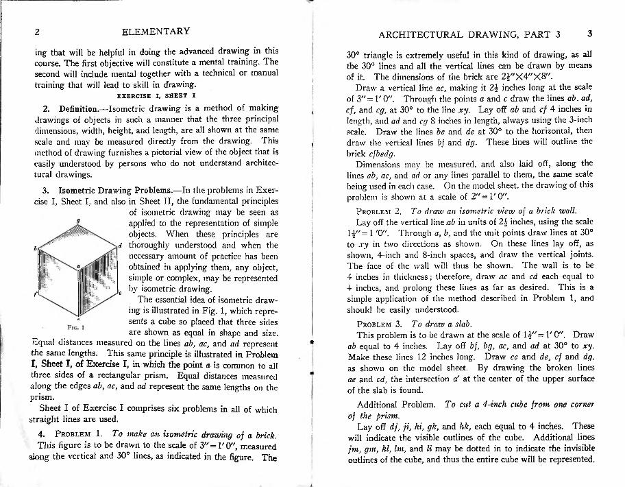
c by isometric drawing.The essential idea of isometric draw
ing is illustrated in Fig. 1, which represents a cube so placed that three sides are shown as equal in shape and size.
Equal distances measured on the lines ab, ac, and ad represent the same lengths.T, Sheet I, of Exercise I, in which the point a is common to all three sides of a rectangular prism. Equal distances measured along the edges ab, ac, and ad represent the same lengths on the prism.
Sheet I of Exercise I comprises six problems in all of which straight lines are used.
4. Problem 1. To make an isometric drawing of a brick.This figure is to be drawn to the scale of 3//=l'0'/, measured
along the vertical and 30° lines, as indicated in the figure. The
30° triangle is extremely useful in this kind of drawing, as all the 30° lines and all the vertical lines can be drawn by means of it. The dimensions of the brick are 2£"X4"X8".
Draw a vertical line ac, making it 24 inches long at the scale of 3"= 1' 0". Through the points a and c draw the lines ab. ad, cf, and eg, at 30° to the line xy. Lay off ab and cf 4 inches in length, and ad and eg 8 inches in length, always using the 3-inch scale. Draw the lines be and de at 30° to the horizontal, then draw the vertical lines bf and dg. These lines will outline the brick cfbedg.
Dimensions may be measured, and also laid off, along the lines ab, ac, and ad or any lines parallel to them, the same scale being used in each case. On the model sheet, the drawing of this problem is shown at a scale of 2"=1'0".
Problem 2. To draw an isometric vieiv of a brick wall.Lay off the vertical line ab in units of 2\ inches, using the scale
14"= 1 '0". Through a, b, and the unit points draw lines at 30° to xy in two directions as shown. On these lines lay off, as shown, 4-inch and 8-inch spaces, and draw the vertical joints. The face of the wall will thus be shown. The wall is to be 4 inches in thickness; therefore, draw ac and cd each equal to 4 inches, and prolong these lines as far as desired. This is a simple application of the method described in Problem 1, and should be easily understood.
Problem 3. To draw a slab.This problem is to be drawn at the scale of 14"= V 0". Draw
ab equal to 4 inches. Lay off bf, bg, ac, and ad at 30° to xy. Make these lines 12 inches long. Draw ce and de, cf and dg, as shown on the model sheet. By drawing the broken lines ae and cd, the intersection af at the center of the upper surface of the slab is found.
Additional Problem. To cut a 4-inch cube from one corner of the prism.
Lay off dj, ji, hi, gk, and hk, each equal to 4 inches. These will indicate the visible outlines of the cube. Additional lines jm, gm, kl, Im, and li may be dotted in to indicate the invisible outlines of the cube, and thus the entire cube will be represented.
The first objective will constitute a mental training. The
i
!
b
f
This same principle is illustrated in Problem
elementary4 ARCHITECTURAL DRAWING, PART 3 5
Additional Problem. To cut a three-sided prism, from the targe prism.
Draw the lines cn, co, and fq each equal to 3 inches. Draw oq, fp, and on. The triangular prism is shown at conqfp. These additional problems are to be shown on the Sheet I sent to the Schools.
Problem 4. A study in prisms.Use the methods already described, and the 1J"=1'0" scale,
and lay out the dimensions shown. There should be no difficulty about making this drawing, which will illustrate clearly the application of isometric principles.
Problem 5. A study of a pyramid.The prism agdbef and the triangles alii, gkj, and fml at the
corners are drawn as in Problem 3. Draw cn equal to 12 inches at the scale of 0". Draw the lines kn, jn, in,tin, In, and mn. These lines will outline the visible mass of the pyramid. The remaining edges are indicated by the dotted lines on, op, and pit.
As none of the lines hn, in, jn, kn, pn, on, mil, and In, are parallel to ab, af, and ag, they cannot be scaled.
Problem 6. To draw a mortise joint.Problem 6 is a special application of isometric drawing to the
representation of a mortise and tenon. By following closely and accurately the dimensions given and using the scale 1£"=1'0", this drawing should be easily made.
5. Inking in the Drawings.—After the drawings have been accurately drawn in pencil, they may be inked in. Heavy lines are used for the final figures, broken lines for the construction lines, and thin lines for dimension lines. Mark the pen as described in Elementary Architectural Drawing, Part 1, and these marks in making lines of uniform thickness.
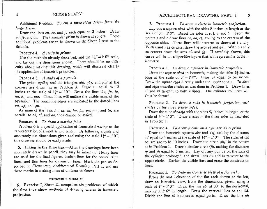
7. Problem 1. To draw a circle in isometric projection.Lay out a square abed with the sides 8 inches in length at the
scale of 3" = l'O". Bisect the sides at e, f, g, and h. From the points a and c draw lines ae, ah, cf, and eg to the centers of the opposite sides. These lines will intersect as shown at i and j. With i and j as centers, draw the arcs ef and gh. With a and c as centers draw the arcs eh and fg. If carefully drawn, this curve will be an ellipse-like figure that will represent a circle in isometric.
Problem 2. To draw a cylinder in isometric projection.Draw the square abed in isometric, making the sides 5£ inches
long at the scale of 3"=1' 0". Draw ae equal to 5^ inches. Draw the square efgh directly under the upper square. In abed and efgh inscribe circles as was done in Problem 1. Draw lines ij and kl tangent to both ellipses. The cylinder required will thus be formed.
Problem 3. To draw a cube in isometric projection, with circles on the three visible sides.
Draw the cube abedefg with the sides 5 J inches in length, at the scale of 3"=1'0". Draw circles in the three sides as described in Problem 1.
Problem 4. To draw a cone on a cylinder on a prism.Draw the isometric squares abc and def, making the distance
ad equal to 4 inches at the scale of lJ/,= 1' Of'. The sides of the square are to be 10 inches. Draw the circle ghji in the square as in Problem 1. Draw a similar circle ijk, making the distances ig and jli equal to 5 inches. Lay off any point l on the axis of the cylinder prolonged, and draw lines Im and In tangent to the upper circle. Darken the visible lines and erase the construction lines.use
Problem 5. To draw an isometric view of a flat arch.From the small elevation of the flat arch shown at the left,
draw an isometric view, from the dimensions given, using a scale of J" = 1'0". Draw the line ab, at 30° to the horizontal, making it 3'6" in length. Draw the vertical lines ac and bd. Divide the line ab into seven equal parts. Draw the line gh
EXERCISE I, SHEET II
6. Exercise I, Sheet II, comprises six problems, of which the first tour show methods of drawing circles in isometric projection.
?ARCHITECTURAL DRAWING, PART 3ELEMENTARY6
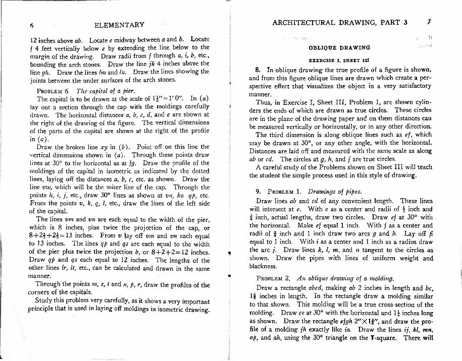
12 inches above ab. Locate e midway between a and b. Locate / 4 feet vertically below e by extending the line below to the margin of the drawing. Draw radii from f through a, i, b, etc., bounding the arch stones. Draw the line jk 4 inches above the line gh. Draw the lines Ini and In. Draw the lines showing the joints between the under surfaces of the arch stones.
Problem 6. The capital of a pier.The capital is to be drawn at the scale of 1£"=1' 0". In (o)
lay out a section through the cap with the moldings carefully drawn. The horizontal distances a, b, c, d, and e are shown at the right of the drawing of the figure. The vertical dimensions of the parts of the capital are shown at the right of the profile in
Draw the broken line xy in (b). Point off on this line the vertical dimensions shown in (a). Through these points draw lines at 30° to the horizontal as at fg. Draw the profile of the moldings of the capital in isometric as indicated by the dotted lines, laying off the distances a, b, c, etc. as shown. Draw the line mo, which will be the miter line of the cap. Through the points h, i, j, etc., draw 30° lines as shown at vn, ko qp, etc. From the points v, k, q, l, etc., draw the lines of the left side of the capital.
The lines vm and vn are each equal to the width of the pier, which is 8 inches, plus twice the projection of the cap, or 8+24+2^=13 inches. From v lay off vm and vn each equal to 13 inches. The lines qp and qs are each equal to the width of the pier plus twice the projection b, or 8+2+2=12 inches. Draw qp and qs each equal to 12 inches. The lengths of the other lines Ir, It, etc., can be calculated and drawn in the same manner.
Through the points m, s, t and n, p, r, draw the profiles of the corners of the capitals.
Study this problem very carefully, as it shows a very important principle that is used in laying off moldings in isometric drawing.
OBLIQUE DRAWING
EXERCISE I, SHEET III8. In oblique drawing the true profile of a figure is shown,
and from this figure oblique lines are drawn which create a perspective effect that visualizes the object in a very satisfactory manner.
Thus, in Exercise I, Sheet III, Problem 1, are shown cylinders the ends of which are drawn as true circles. These circles are in the plane of the drawing paper and on them distances can be measured vertically or horizontally, or in any other direction.
The third dimension is along oblique lines such as ef, which may be drawn at 30°, or any other angle, with the horizontal. Distances are laid off and measured with the same scale as along ab or cd. The circles at g, h, and ; are true circles.
A careful study of the Problems shown on Sheet III will teach the student the simple process used in this style of drawing.
i
i
9. Problem 1. Drawings of pipes.Draw lines ab and cd of any convenient length. These lines
will intersect at e. With e as a center and radii of 4 inch and } inch, actual lengths, draw two circles. Draw ef at 30° with the horizontal. Make ef equal 1 inch. With f as a center and radii of f inch and 1 inch draw two arcs g and h. Lay off fi equal to 1 inch. With i as a center and 1 inch as a radius draw the arc j. Draw lines k, l, m, and n tangent to the circles as shown. Draw the pipes with lines of uniform weight and blackness.
Problem 2. An oblique drawing of a molding.Draw a rectangle abed, making ab 2 inches in length and be,
ljf inches in length. In the rectangle draw a molding similar to that shown. This molding will be a true cross-section of the molding. Draw ce at 30° with the horizontal and 1J inches long as shown. Draw the rectangle efgh 2"Xlf,/, and draw the profile of a molding jh exactly like ia. Draw the lines ij, kl, mn, op, and ah, using the 30° triangle on the T-square. There will
*
m
L
9ARCHITECTURAL DRAWING, PART 3ELEMENTARY
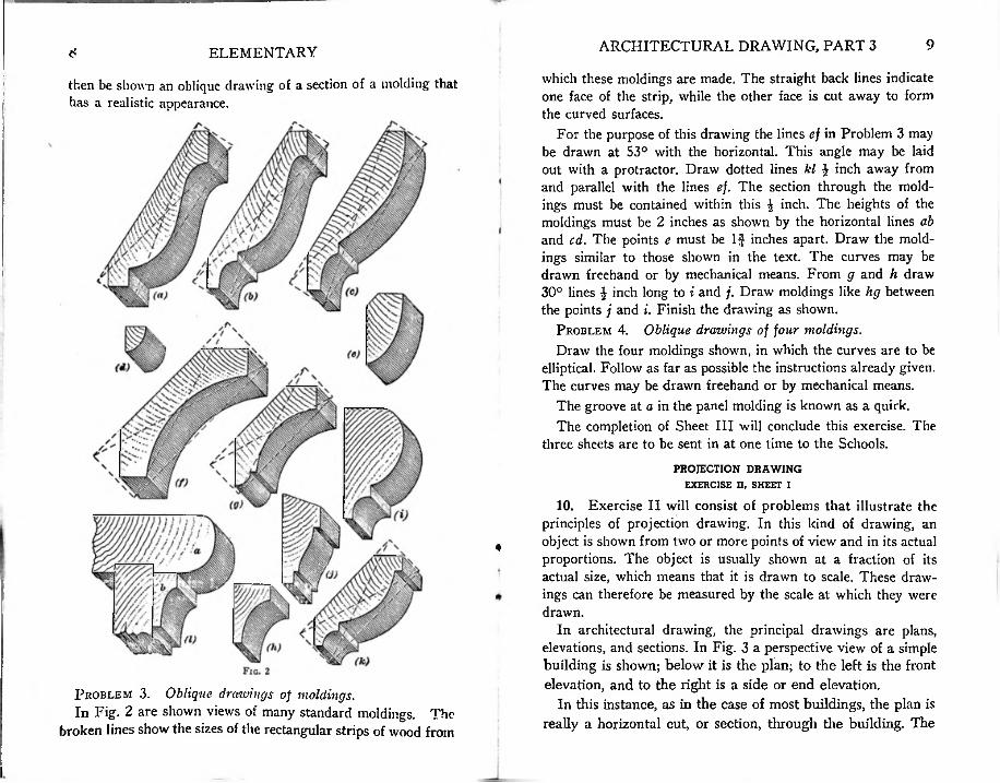
which these moldings are made. The straight back lines indicate one face of the strip, while the other face is cut away to form the curved surfaces.
For the purpose of this drawing the lines ef in Problem 3 may be drawn at 53° with the horizontal. This angle may be laid out with a protractor. Draw dotted lines kl £ inch away from and parallel with the lines ef. The section through the moldings must be contained within this £ inch. The heights of the moldings must be 2 inches as shown by the horizontal lines ab and cd. The points e must be If inches apart. Draw the moldings similar to those shown in the text. The curves may be drawn freehand or by mechanical means. From g and h draw 30° lines £ inch long to i and j. Draw moldings like hg between the points j and i. Finish the drawing as shown.
Problem 4. Oblique drawings of four moldings.Draw the four moldings shown, in which the curves are to be
elliptical. Follow as far as possible the instructions already given. The curves may be drawn freehand or by mechanical means.
The groove at a in the panel molding is known as a quirk.The completion of Sheet III will conclude this exercise. The
three sheets are to be sent in at one time to the Schools.PROJECTION DRAWING
EXERCISE II. SHEET I
10. Exercise II will consist of problems that illustrate the principles of projection drawing. In this kind of drawing, an object is shown from two or more points of view and in its actual proportions. The object is usually shown at a fraction of its actual size, which means that it is drawn to scale. These drawings can therefore be measured by the scale at which they were drawn.
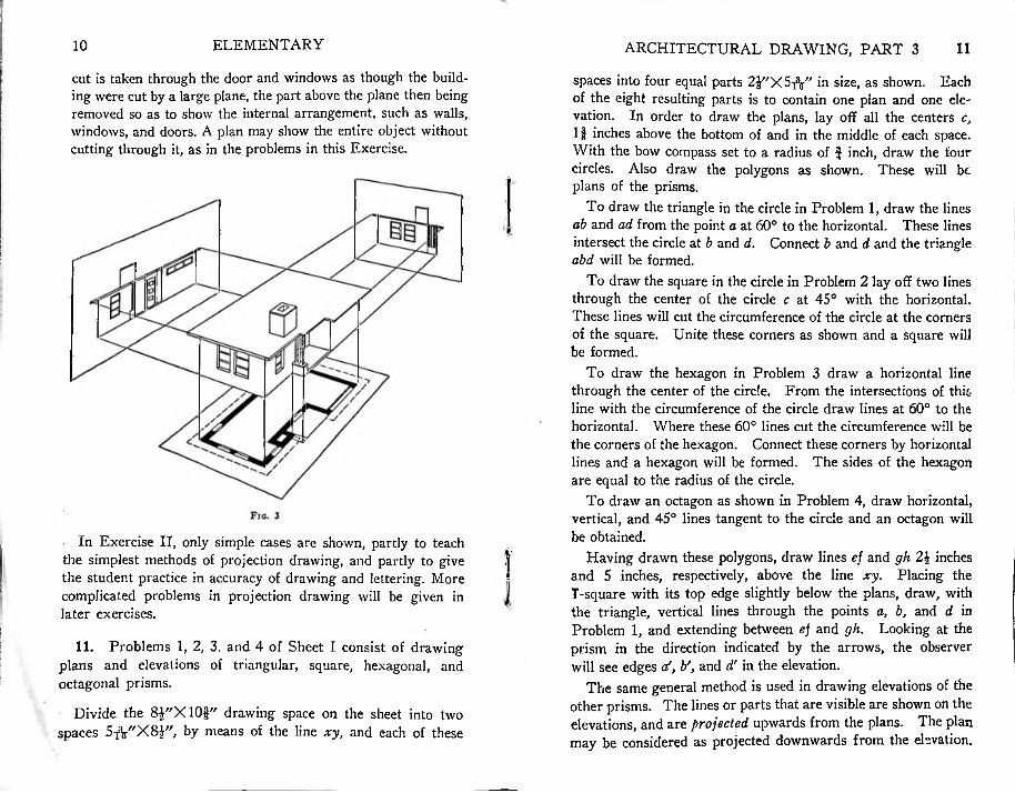
In architectural drawing, the principal drawings are plans, elevations, and sections. In Fig. 3 a perspective view of a simple building is shown; below it is the plan; to the left is the front elevation, and to the right is a side or end elevation.
In this instance, as in the case of most buildings, the plan is really a horizontal cut, or section, through the building. The
then be shown an oblique drawing of a section of a molding that has a realistic appearance.
t
Problem 3. Oblique drawings of moldings.In Fig. 2 are shown views of many standard moldings. The
broken lines show the sizes of the rectangular strips of wood from
ELEMENTARY10 ARCHITECTURAL DRAWING, PART 3 11
cut is taken through the door and windows as though the building were cut by a large plane, the part above the plane then being removed so as to show the internal arrangement, such as walls, windows, and doors. A plan may show the entire object without cutting through it, as in the problems in this Exercise.
spaces into four equal parts in size, as shown. Eachof the eight resulting parts is to contain one plan and one elevation. In order to draw the plans, lay off all the centers c, If inches above the bottom of and in the middle of each space. With the bow compass set to a radius of £ inch, draw the four circles. Also draw the polygons as shown. These will be plans of the prisms.
To draw the triangle in the circle in Problem 1, draw the lines ab and ad from the point a at 60° to the horizontal. These lines intersect the circle at b and d. Connect b and d and the triangle abd will be formed.
To draw the square in the circle in Problem 2 lay off two lines through the center of the circle c at 45° with the horizontal. These lines will cut the circumference of the circle at the corners of the square. Unite these corners as shown and a square will be formed.
To draw the hexagon in Problem 3 draw a horizontal line through the center of the circle. From the intersections of this line with the circumference of the circle draw lines at 60° to the horizontal. Where these 60° lines cut the circumference will be the corners of the hexagon. Connect these corners by horizontal lines and a hexagon will be formed. The sides of the hexagon are equal to the radius of the circle.
To draw an octagon as shown in Problem 4, draw horizontal, vertical, and 45° lines tangent to the circle and an octagon will be obtained.
Having drawn these polygons, draw lines ef and gh 2\ inches and 5 inches, respectively, above the line xy. Placing the T-square with its top edge slightly below the plans, draw, with the triangle, vertical lines through the points a, b, and d in Problem 1, and extending between ej and gh. Looking at the prism in the direction indicated by the arrows, the observer will see edges af, b', and d' in the elevation.
The same general method is used in drawing elevations of the other prisms. The lines or parts that are visible are shown on the elevations, and are projected upwards from the plans. The plan may be considered as projected downwards from the elevation.
In Exercise II, only simple cases are shown, partly to teach the simplest methods of projection drawing, and partly to give the student practice in accuracy of drawing and lettering. More complicated problems in projection drawing will be given in later exercises.
11. Problems 1, 2, 3, and 4 of Sheet I consist of drawing plans and elevations of triangular, square, hexagonal, and octagonal prisms.
Divide the 8J"X10§" drawing space on the sheet into two spaces 5TV'X8i", by means of the line xy, and each of these
12 ELEMENTARY 13ARCHITECTURAL DRAWING, PART 3
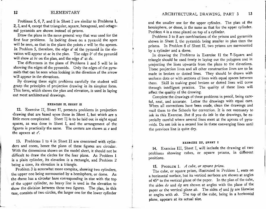
Problems 5, 6, 7, and 8 in Sheet I are similar to Problems 1, 2, 3, and 4, except that triangular, square, hexagonal, and octagonal pyramids are shown instead of prisms.
Draw the plans in the same general way that was used for the first four problems. In looking down on a pyramid the apex will be seen, so that in the plans the points c will be the apexes. In Problem 5, therefore, the edge a? of the pyramid in the elevation will appear at ac in the plan. The edge b' of the pyramid will show at be on the plan, and the edge d' at dc.
The differences in the plans of Problems 1 and 5 will be in showing the edges of the pyramids. Only the edges of the pyramids that can be seen when looking in the direction of the arrow will appear in the elevations.
By drawing these eight problems carefully the student will grasp the principles of projection drawing in its simplest form. This form, which shows the plan and elevation, is used in laying out most architectural drawings.
and the smaller one for the upper cylinder. The plan of the hemisphere, or dome, is the same as that for the upper cylinder. Problem 4 is a cone placed on top of a cylinder.
Problems 5 to 8 are combinations of the prisms and pyramids shown in Sheet I, the pyramids being smaller in plan than the prisms. In Problem 8 of Sheet II, two prisms are surmounted by a cylinder and a dome.
In drawing the Problems in Exercise II the T-Square and triangle should be used freely in laying out the polygons and in projecting the lines upwards from the plans to the elevations. These projection lines and all other construction lines are to be made in broken or dotted lines. They should be drawn with uniform dots or with sections of lines with equal spaces between them. Skill in making good broken or dotted lines will come through intelligent practice. The quality of these lines will affect the quality of the drawing.
Complete the drawings of these problems in pencil, being careful, neat, and accurate. Letter the drawings with equal care. When all corrections have been made, clean the drawings and mail them to the Schools for correction. It is not necessary to ink in this Exercise. But if you do ink in the drawings, be especially careful where several lines meet at the apexes of pyramids. Do not ink in a second line in these converging lines until the previous line is quite dry.
!
>
f
:' ■
:
EXERCISE II, SHEET II12. Exercise II, Sheet II, presents problems in projection
drawing that are based upon those in Sheet I, but which are a little more complicated. Sheet II is to be laid out in eight equal spaces, as was done in Sheet I, and the arrangement of the figures is practically the same. The centers are shown at c and the apexes at </.
13. Problems 1 to 4 in Sheet II are concerned with cylinders and cones, hence the plans of these figures are circular. With the dimensions shown on the model sheet, it should not be difficult to draw the circles for the four plans. As Problem 1 is a plain cylinder, its elevation is a rectangle, and Problem 2 being a cone, its elevation is a triangle.
Problem 3 is somewhat more complex, showing two cylinders, the upper one being surmounted by a hemisphere, or dome. As the dome has a circular base corresponding in size with the top of the upper cylinder, no heavy line is used in the elevation to show the division between these two figures. The plan, in this case, consists of two circles, the larger one for the lower cylinder
EXERCISE III, SHEET I£ 14. Exercise III, Sheet I, will include the drawing of two
in differentproblems showing cubes, or square prisms,positions.V
15. Problem 1. A cube, or square prism.The cube, or square prism, illustrated in Problem 1, rests on
a horizontal surface, but its vertical surfaces are shown at angles of 45° to the vertical plane of the paper. In the plan of the cube, the sides dc and dg are shown at angles with the plane of the paper or the vertical plane ab. The sides ef and fg are likewise at angles with ab. The top of the cube, being in a horizontal plane, appears at its actual size.
L-----
i
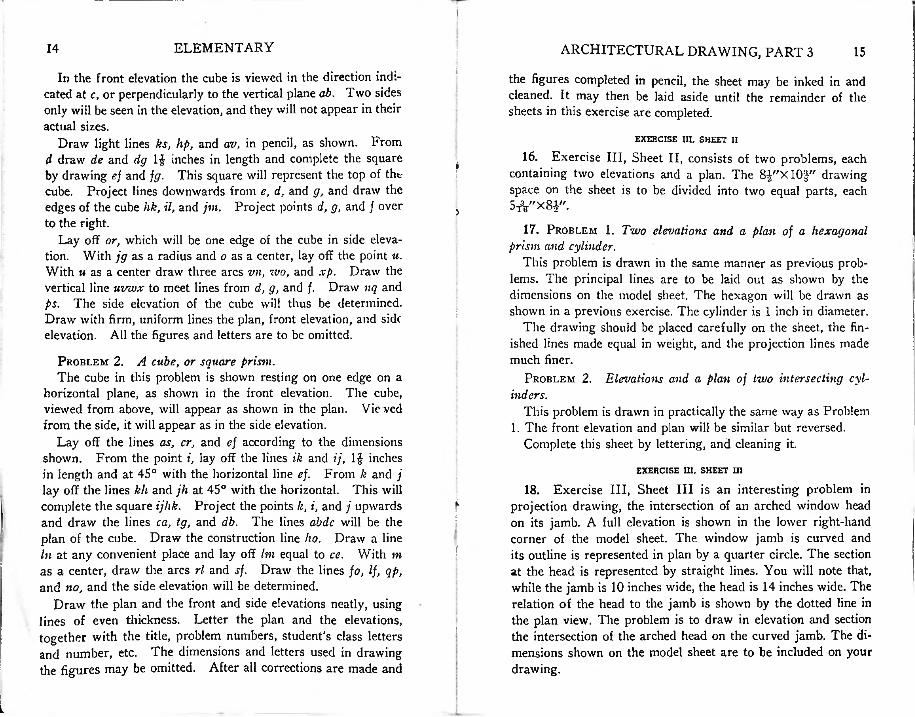
ELEMENTARY14 ARCHITECTURAL DRAWING, PART 3 15,In the front elevation the cube is viewed in the direction indi
cated at c, or perpendicularly to the vertical plane ab. Two sides only will be seen in the elevation, and they will not appear in their actual sizes.
Draw light lines ks, hp, and av, in pencil, as shown. From d draw de and dg If inches in length and complete the square by drawing ef and fg. This square will represent the top of the cube. Project lines downwards from e, d, and g, and draw the edges of the cube hk, il, and jm. Project points d, g, and / over to the right.
Lay off or, which will be one edge of the cube in side elevation. With jg as a radius and o as a center, lay off the point u. With u as a center draw three arcs vn, wo, and xp. Draw the vertical line uvwx to meet lines from d, g, and /. Draw nq and ps. The side elevation of the cube will thus be determined. Draw with firm, uniform lines the plan, front elevation, and side elevation. All the figures and letters are to be omitted.
Problem 2. A cube, or square prism.The cube in this problem is shown resting on one edge on a
horizontal plane, as shown in the front elevation. The cube, viewed from above, will appear as shown in the plan. Viewed from the side, it will appear as in the side elevation.
Lay off the lines as, cr, and ef according to the dimensions shown. From the point i, lay off the lines ik and ij, 1$ inches in length and at 45° with the horizontal line ef. From k and j lay off the lines kh and jh at. 45° with the horizontal. This will complete the square ijhk. Project the points k, i, and j upwards and draw the lines ca, tg, and db. The lines abdc will be the plan of the cube. Draw the construction line ho. Draw a line In at any convenient place and lay off Im equal to ce. With m as a center, draw the arcs rl and sf. Draw the lines fo, If, qp, and no, and the side elevation will be determined.
Draw the plan and the front and side elevations neatly, using lines of even thickness. Letter the plan and the elevations, together with the title, problem numbers, student’s class letters and number, etc. The dimensions and letters used in drawing the figures may be omitted. After all corrections are made and
the figures completed in pencil, the sheet may be inked in and cleaned. It may then be laid aside until the remainder of the sheets in this exercise are completed.
EXERCISE III, SHEET II
16. Exercise III, Sheet II, consists of two problems, each containing two elevations and a plan. The 8^"XlO-}" drawing space on the sheet is to be divided into two equal parts, each 5*"x8i"
17. Problem 1. Two elevations and a plan of a hexagonal prism and cylinder.
This problem is drawn in the same manner as previous problems. The principal lines are to be laid out as shown by the dimensions on the model sheet. The hexagon will be drawn as shown in a previous exercise. The cylinder is 1 inch in diameter.
The drawing should be placed carefully on the sheet, the finished lines made equal in weight, and the projection lines made much finer.
Problem 2. Elevations and a plan of two intersecting cylinders.
This problem is drawn in practically the same way as Problem 1. The front elevation and plan will be similar but reversed.
Complete this sheet by lettering, and cleaning it.
EXERCISE HI, SHEET UI
18. Exercise III, Sheet III is an interesting problem in projection drawing, the intersection of an arched window head on its jamb. A full elevation is shown in the lower right-hand corner of the model sheet. The window jamb is curved and its outline is represented in plan by a quarter circle. The section at the head is represented by straight lines. You will note that, while the jamb is 10 inches wide, the head is 14 inches wide. The relation of the head to the jamb is shown by the dotted line in the plan view. The problem is to draw in elevation and section the intersection of the arched head on the curved jamb. The dimensions shown on the model sheet are to be included on your drawing.
f
i
!
:
?
!
L
ARCHITECTURAL DRAWING, PART 316 ELEMENTARY 17
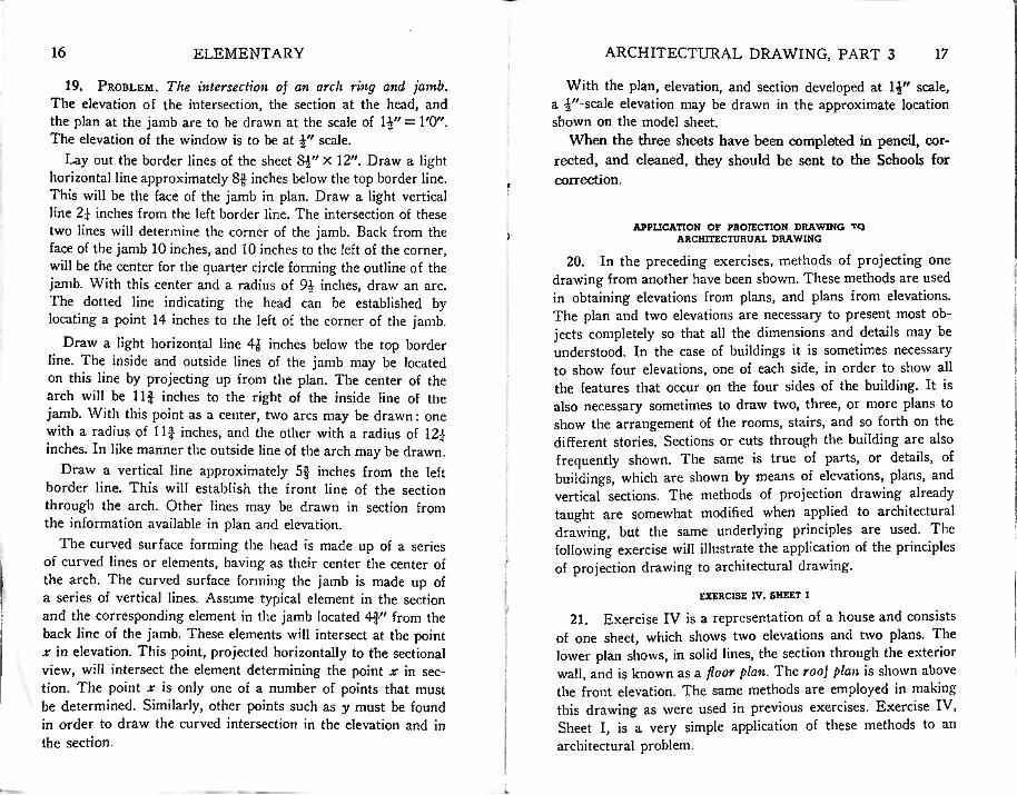
With the plan, elevation, and section developed at 1-J" scale, a |"-scale elevation may be drawn in the approximate location shown on the model sheet.
When the three sheets have been completed in pencil, corrected, and cleaned, they should be sent to the Schools for correction.
19. Problem. The intersection of an arch ring and jamb. The elevation of the intersection, the section at the head, and the plan at the jamb are to be drawn at the scale of IV' = l'O". The elevation of the window is to be at scale.
Lay out the border lines of the sheet 8£" X 12". Draw a light horizontal line approximately 8$ inches below the top border line. This will be the face of the jamb in plan. Draw a light vertical line 2} inches from the left border line. The intersection of these two lines will determine the corner of the jamb. Back from the face of the jamb 10 inches, and 10 inches to the left of the corner, will be the center for the quarter circle forming the outline of the jamb. With this center and a radius of 94 inches, draw an arc. The dotted line indicating the head can be established by locating a point 14 inches to the left of the corner of the jamb.
Draw a light horizontal line 4& inches below the top border line. The inside and outside lines of the jamb may be located on this line by projecting up from the plan. The center of the arch will be Ilf inches to the right of the inside line of the jamb. With this point as a center, two arcs may be drawn: one with a radius of Ilf inches, and the other with a radius of 12f inches. In like manner the outside line of the arch may be drawn.
Draw a vertical line approximately 5$ inches from the left border line. This will establish the front line of the section through the arch. Other lines may be drawn in section from the information available in plan and elevation.
The curved surface forming the head is made up of of curved lines or elements, having as their center the center of the arch. The curved surface forming the jamb is made up of a series of vertical lines. Assume typical element in the section and the corresponding element in the jamb located 4f" from the back line of the jamb. These elements will intersect at the point x in elevation. This point, projected horizontally to the sectional view, will intersect the element determining the point x in section. The point x is only one of a number of points that must be determined. Similarly, other points such as y must be found in order to draw the curved intersection in the elevation and in the section.
APPLICATION OF PROJECTION DRAWING TQ ARCHITECTURUAL DRAWING
20. In the preceding exercises, methods of projecting one drawing from another have been shown. These methods are used in obtaining elevations from plans, and plans from elevations. The plan and two elevations are necessary to present most objects completely so that all the dimensions and details may be understood. In the case of buildings it is sometimes necessary to show four elevations, one of each side, in order to show all the features that occur on the four sides of the building. It is also necessary sometimes to draw two, three, or more plans to show the arrangement of the rooms, stairs, and so forth on the different stories. Sections or cuts through the building are also frequently shown. The same is true of parts, or details, of buildings, which are shown by means of elevations, plans, and vertical sections. The methods of projection drawing already taught are somewhat modified when applied to architectural drawing, but the same underlying principles are used. The following exercise will illustrate the application of the principles of projection drawing to architectural drawing.
EXERCISE IV, SHEET I
21. Exercise IV is a representation of a house and consists of one sheet, which shows two elevations and two plans. The lower plan shows, in solid lines, the section through the exterior wall, and is known as a floor plan. The roof plan is shown above the front elevation. The same methods are employed in making this drawing as were used in previous exercises. Exercise IV, Sheet I, is a very simple application of these methods to an architectural problem.
y
i
:.
ia series
'
i
!ELEMENTARY ARCHITECTURAL DRAWING, PART 3 1918
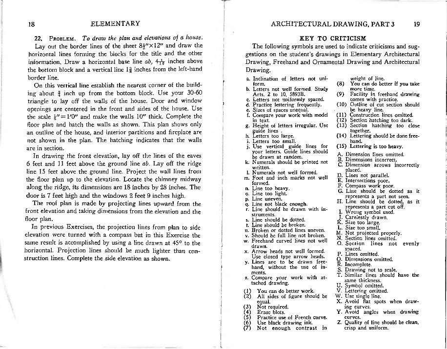
f22. Problem. To draw the plan and elevations oj a house.Lay out the border lines of the sheet 8£"Xl2" and draw the
horizontal lines forming the blocks for the title and the other information. Draw a horizontal base line ab, 4-j^ inches above the bottom block and a vertical line 1$ inches from the left-hand border line.
On this vertical line establish the nearest corner of the building about $ inch up from the bottom block. Use your 30-60 triangle to lay off the walls of the house. Door and window openings are centered in the front and sides of the house. Use the scale J"=1,0" and make the walls 10" thick. Complete the floor plan and hatch the walls as shown. This plan shows only an outline of the house, and interior partitions and fireplace are not shown in the plan. The hatching indicates that the walls are in section.
In drawing the front elevation, lay off the lines of the eaves 6 feet and 11 feet above the ground line ab. Lay off the ridge line 15 feet above the ground line. Project the wall lines from the floor plan up to the elevation. Locate the chimney midway along the ridge, its dimensions are 18 inches by 28 inches. The door is 7 feet high and the windows 2 feet 9 inches high.
The roof plan is made by projecting lines upward from the front elevation and taking dimensions from the elevation and the floor plan.
In previous Exercises, the projection lines from plan to side elevation were turned with a compass but in this Exercise the same result is accomplished by using a line drawn at 45° to the horizontal. Projection lines should be much lighter than construction lines. Complete the side elevation as shown.
KEY TO CRITICISMThe following symbols are used to indicate criticisms and sug
gestions on the student’s drawings in Elementary Architectural Drawing, Freehand and Ornamental Drawing and Architectural Drawing.a. Inclination of letters not uni
form.b. Letters not well formed. Study
Arts. 2 to 10, 5893B.c. Letters not uniformly spaced.d. Practice lettering frequently.e. Sizes of spaces unequal.f. Compare your work with model
in text.g. Height of letters irregular. Use
guide lines .h. Letters too large.i. Letters too small.j. Use vertical guide lines for
your letters. Guide lines should be drawn at random.
k. Numerals should be printed not written.
l. Numerals not well formed.m. Foot and inch marks not well
formed.n. Line too heavy.o. Line too light.p. Line uneven.q. Line not black enough.r. Line should be drawn with in
struments.s. Line should be dotted.t. Line should be broken.u. Broken or dotted lines uneven.v. Should be full line not broken.
w. Freehand curved lines not well drawn.
x. Arrow heads not well formed.Use closed type arrow heads.
y. Lines are to be drawn freehand, without the use of in- ments.
z. Compare your work with attached drawing.
You can do better work.All sides of figure should be equal.Not required.Erase blots.
(5) Practice use of French curve.(6) Use black drawing ink.(7) Not enough contrast in
II
weight of line.(8) You can do better if you take
more time.(9) Facility in freehand drawing
comes with practice.(10) Outline of cut section should
be heavy line.(11) Construction lines omitted.(12) Section hatching too dark.(13) Section hatching too close
together.(14) Lettering should be done free
hand.(15) Lettering is too heavy.A. Dimension lines omitted.B. Dimensions incorrect.C. Dimension arrows incorrectly
placed.D. Lines not parallel.E. Intersections poor.F. Compass work poor.G. Line should be dotted as it
represents a part not seen.H. Line should be dotted, as it
represents a part cut off.I. Wrong symbol used.J. Carelessly drawn.K. Size too large.L. Size too small.
M. Not projected properly.N. Section lines omitted.O. Section lines not evenly
spaced.P. Lines omitted.Q. Dimensions omitted.R. Incomplete.S. Drawing not to scale.T. Similar lines should have the
same thickness.U. Symbol omitted.V. Lettering omitted.
W. Use single line.X. Avoid flat spots when draw
ing curves.Y. Avoid angles when drawing
curves.Z. Quality of line should be clean,
crisp and uniform.
f
>i'
Ii!
I■
:i!
j
i
1f
I $
(3)(4)
:
720 (07) 157 v.7 pt.3
International Correspondence Schools, Scranton, Pa.
Architecture home study course, v.7 pt.3.
ISSUED TODATE
<
/
/
VL
i
I?
bL