Embed Size (px)
Citation preview
QA-ES II Electrosurgical Analyzer
Users Manual
PN 2716032 October 2006 © 2006 Fluke Corporation, All rights reserved. Printed in USA All product names are trademarks of their respective companies.

Warranty and Product Support
Fluke Biomedical warrants this instrument against defects in materials and workmanship for one full year from the date of original purchase. During the warranty period, we will repair or, at our option, replace at no charge a product that proves to be defective, provided you return the product, shipping prepaid, to Fluke Biomedical. This warranty does not apply if the product has been damaged by accident or misuse or as the result of service or modification by other than Fluke Biomedical. IN NO EVENT SHALL FLUKE BIOMEDICAL BE LIABLE FOR CONSEQUENTIAL DAMAGES.
Only serialized products and their accessory items (those products and items bearing a distinct serial number tag) are cov-ered under this one-year warranty. PHYSICAL DAMAGE CAUSED BY MISUSE OR PHYSICAL ABUSE IS NOT COVERED UNDER THE WARRANTY. Items such as cables and nonserialized modules are not covered under this warranty.
Recalibration of instruments is not covered under the warranty.
This warranty gives you specific legal rights, and you may also have other rights which vary from state to state, province to province, or country to country. This warranty is limited to repairing the instrument to Fluke Biomedical’s specifications.
Warranty Disclaimer
Should you elect to have your instrument serviced and/or calibrated by someone other than Fluke Biomedical, please be advised that the original warranty covering your product becomes void when the tamper-resistant Quality Seal is removed or broken without proper factory authorization. We strongly recommend, therefore, that you send your instrument to Fluke Bio-medical for factory service and calibration, especially during the original warranty period.
Notices
All Rights Reserved © Copyright 2006, Fluke Biomedical. No part of this publication may be reproduced, transmitted, transcribed, stored in a retrieval system, or translated into any language without the written permission of Fluke Biomedical.
Copyright Release Fluke Biomedical agrees to a limited copyright release that allows you to reproduce manuals and other printed materials for use in service training programs and other technical publications. If you would like other reproductions or distributions, submit a written request to Fluke Biomedical.
Unpacking and Inspection Follow standard receiving practices upon receipt of the instrument. Check the shipping carton for damage. If damage is found, stop unpacking the instrument. Notify the carrier and ask for an agent to be present while the instrument is unpacked. There are no special unpacking instructions, but be careful not to dam-age the instrument when unpacking it. Inspect the instrument for physical damage such as bent or broken parts, dents, or scratches.
Technical Support For application support or answers to technical questions, either email [email protected] or call 1-800- 648-7942 or 1-425-446-6945.
Claims Our routine method of shipment is via common carrier, FOB origin. Upon delivery, if physical damage is found, retain all packing materials in their original condition and contact the carrier immediately to file a claim. If the instrument is delivered in good physical condition but does not operate within specifica-tions, or if there are any other problems not caused by shipping damage, please contact Fluke Biomedical or your local sales representative.
Standard Terms and Conditions Refunds and Credits
Please note that only serialized products and their accessory items (i.e., products and items bearing a distinct serial number tag) are eligible for partial refund and/or credit. Nonserialized parts and accessory items (e.g., cables, carrying cases, auxiliary modules, etc.) are not eligible for re-turn or refund. Only products returned within 90 days from the date of original purchase are eligible for refund/credit. In order to receive a partial re-fund/credit of a product purchase price on a serialized product, the product must not have been damaged by the customer or by the carrier chosen by the cus-tomer to return the goods, and the product must be returned complete (meaning with all manuals, cables, accessories, etc.) and in “as new” and resalable con-dition. Products not returned within 90 days of purchase, or products which are not in “as new” and resalable condition, are not eligible for credit return and will be returned to the customer. The Return Procedure (see below) must be followed to assure prompt refund/credit.
Restocking Charges Products returned within 30 days of original purchase are subject to a minimum restocking fee of 15 %. Products returned in excess of 30 days af-ter purchase, but prior to 90 days, are subject to a minimum restocking fee of 20 %. Additional charges for damage and/or missing parts and accesso-ries will be applied to all returns.
Return Procedure All items being returned (including all warranty-claim shipments) must be sent freight-prepaid to our factory location. When you return an instrument to Fluke Biomedical, we recommend using United Parcel Service, Federal Express, or Air Parcel Post. We also recommend that you insure your shipment for its actual replacement cost. Fluke Biomedical will not be responsible for lost shipments or instruments that are received in damaged condition due to improper packaging or handling. Use the original carton and packaging material for shipment. If they are not available, we recommend the following guide for repackaging:
Use a double–walled carton of sufficient strength for the weight being shipped. Use heavy paper or cardboard to protect all instrument surfaces. Use nonabrasive material around all projecting parts. Use at least four inches of tightly packed, industry-approved, shock-absorbent material around the instrument.
Returns for partial refund/credit: Every product returned for refund/credit must be accompanied by a Return Material Authorization (RMA) number, obtained from our Order Entry Group at 1-800-648-7952 or 1-425-446-6945. Repair and calibration: To find the nearest service center, go to www.flukebiomedical.com/service or In the U.S.A.: Cleveland Calibration Lab Tel: 1-800-850-4606 Email: [email protected] Everett Calibration Lab Tel: 1-888-99 FLUKE (1-888-993-5853) Email: [email protected] In Europe, Middle East, and Africa: Eindhoven Calibration Lab Tel: +31-402-675300 Email: [email protected] In Asia: Everett Calibration Lab Tel: +425-446-6945 Email: [email protected]
Certification This instrument was thoroughly tested and inspected. It was found to meet Fluke Biomedical’s manufacturing specifications when it was shipped from the factory. Calibration measurements are traceable to the National Institute of Standards and Technology (NIST). Devices for which there are no NIST calibra-tion standards are measured against in-house performance standards using accepted test procedures.
WARNING Unauthorized user modifications or application beyond the published specifications may result in electrical shock hazards or improper operation. Fluke Bio-medical will not be responsible for any injuries sustained due to unauthorized equipment modifications.

Restrictions and Liabilities Information in this document is subject to change and does not represent a commitment by Fluke Biomedical. Changes made to the information in this document will be incorporated in new editions of the publication. No responsibility is assumed by Fluke Biomedical for the use or reliability of software or equipment that is not supplied by Fluke Biomedical, or by its affiliated dealers.
Manufacturing Location
The QA-ES II Electrosurgical Analyzer is manufactured in Norway for Fluke Biomedical, 6920 Seaway Blvd., Everett, WA, U.S.A.
i
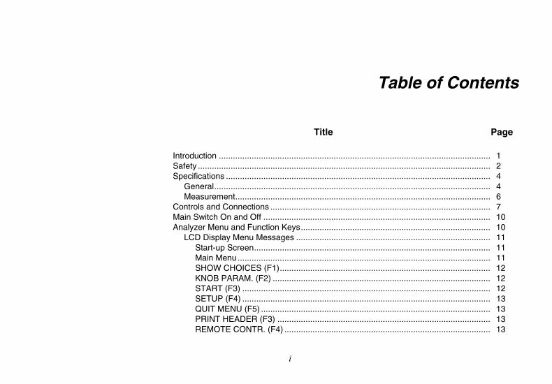
Table of Contents
Title Page Introduction .................................................................................................................... 1 Safety ............................................................................................................................. 2 Specifications ................................................................................................................. 4
General...................................................................................................................... 4 Measurement............................................................................................................. 6
Controls and Connections .............................................................................................. 7 Main Switch On and Off ................................................................................................. 10 Analyzer Menu and Function Keys................................................................................. 10
LCD Display Menu Messages ................................................................................... 11 Start-up Screen..................................................................................................... 11 Main Menu............................................................................................................ 11 SHOW CHOICES (F1).......................................................................................... 12 KNOB PARAM. (F2) ............................................................................................. 12 START (F3) .......................................................................................................... 12 SETUP (F4) .......................................................................................................... 13 QUIT MENU (F5) .................................................................................................. 13 PRINT HEADER (F3) ........................................................................................... 13 REMOTE CONTR. (F4) ........................................................................................ 13
QA-ES II Users Manual
ii
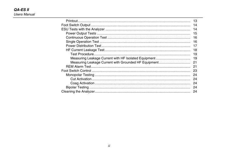
Printout...................................................................................................................... 13 Foot Switch Output ........................................................................................................ 14 ESU Tests with the Analyzer ......................................................................................... 14
Power Output Tests .................................................................................................. 15 Continuous Operation Test ....................................................................................... 16 Single Operation Test ............................................................................................... 16 Power Distribution Test ............................................................................................. 17 HF Current Leakage Test.......................................................................................... 18
Test Procedure..................................................................................................... 19 Measuring Leakage Current with HF Isolated Equipment .................................... 19 Measuring Leakage Current with Grounded HF Equipment................................. 21
REM Alarm Test........................................................................................................ 21 Foot Switch Control ....................................................................................................... 23
Monopolar Testing .................................................................................................... 24 Cut Activation ....................................................................................................... 24 Coag Activation .................................................................................................... 24
Bipolar Testing .......................................................................................................... 24 Cleaning the Analyzer.................................................................................................... 24
iii
List of Tables
Table Title Page
1. Symbols................................................................................................................................. 3 2. Controls and Connectors....................................................................................................... 9 3. Load Resistance.................................................................................................................... 16 4. Leakage Resistance.............................................................................................................. 19 5. Foot Switch Connections....................................................................................................... 23
List of Figures
Figure Title Page
1. Controls and Connectors....................................................................................................... 7 2. Rear Panel ............................................................................................................................ 8 3. Test Results Printout ............................................................................................................. 14 4. ESU Power Output Test ........................................................................................................ 15 5. Power Distribution Test ......................................................................................................... 17 6. Test Setup A.......................................................................................................................... 20 7. Test Setup B.......................................................................................................................... 20 8. Test Setup C ......................................................................................................................... 21 9. Test Setup D ......................................................................................................................... 21 10. REM Alarm Test Setup.......................................................................................................... 22

QA-ES II Users Manual
iv

1
QA-ES II Electrosurgical Analyzer
Introduction The QA-ES II Electrosurgical Analyzer (hereafter called the Analyzer) is a precision instrument for use in performing tests on high-frequency electrosurgical units (ESU) in accordance with national and international standards. It is for use by trained service technicians. Tests include:
• Automatic power distribution measurement
• Crest factor measurement
• RF leak measurement
• Return electrode monitor (REM) test
The Analyzer conducts testing by measuring the ESU output against test loads set and adjusted in the Analyzer. The Analyzer can automatically execute a power distribution test with a load resistance ranging from 10
ohms to 5200 ohms. The Analyzer automatically measures crest factor with a bandwidth of 2.5 MHz (with loads), ensuring that the test result is reliable and reproducible.
Test results shown in the Analyzer’s LCD display can be printed out directly or transferred to a PC via the Ansur QA-ES Plug-in test automation software. The Ansur QA-ES Plug-in software allows you to design test protocols, remotely control the Analyzer, and store test results.
Carefully unpack all items from the box and check that you have the items listed under Standard Accessories.
If you are missing any of these items, or if you find a damaged item, follow the procedures found in the Unpacking and Inspection Notices in the front of this manual.
QA-ES II Users Manual
2
Safety
WXWarning
Read before using the Analyzer. To avoid possible electric shock or personal injury, follow these guidelines:
• Do not use the Analyzer in any manner not specified in the Users Manual. Otherwise, the protection provided by this product may be impaired.
• Always press power off on the Analyzer and unplug the power cord before cleaning the outer surface.
• Inspect the product. If the Analyzer appears damaged or appears to operate in a manner not specified in the manual, DO NOT CONTINUE USE. Return the product for service.
• Avoid spilling liquids on the Analyzer; fluid seepage into internal components creates corrosion and a potential shock hazard. Do not operate the instrument if fluid has contaminated internal components.
• Do not open the Analyzer. There are no user replaceable parts.
• Do not use the Analyzer in CAT II, III, or IV environments.
• Retractable end of test leads are for use on ESU only.
• No probes or accessories supplied with the Analyzer are intended for handheld use. Setup and stand clear when activating the ESU with the footswitch.
Electrosurgical Analyzer Safety
3
WCaution
To avoid damage to the Analyzer:
• Calibrate the Analyzer annually.
• Only qualified technical personnel should perform troubleshooting and service procedures on the Analyzer.
• Do not use the Analyzer for anything other than measuring RF outputs from electrosurgical units.
• Ensure there is at least six inches of air space above and behind the Analyzer to allow air circulation to cool internal load resistors.
• Do not expose the Analyzer to temperature extremes. Ambient operating temperatures should remain between 15 and 35 °C. Analyzer performance may degrade if temperatures fluctuate above or below this range.
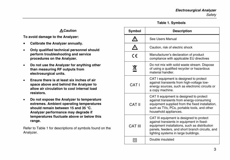
Refer to Table 1 for descriptions of symbols found on the Analyzer.
Table 1. Symbols
Symbol Description
W See Users Manual
X Caution, risk of electric shock
P Manufacturer’s declaration of product compliance with applicable EU directives
~ Do not mix with solid waste stream. Dispose of using a qualified recycler or hazardous material handler.
CAT I
CAT I equipment is designed to protect against transients from high-voltage low-energy sources, such as electronic circuits or a copy machine.
CAT II
CAT II equipment is designed to protect against transients from energy-consuming equipment supplied from the fixed installation, such as TVs, PCs, portable tools, and other household appliances.
CAT III
CAT III equipment is designed to protect against transients in equipment in fixed-equipment installations, such as distribution panels, feeders, and short branch circuits, and lighting systems in large buildings.
T Double insulated
QA-ES II Users Manual
4
Specifications
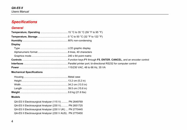
GeneralTemperature, Operating .......................................15 °C to 35 °C (59 °F to 95 °F)
Temperature, Storage ...........................................0 °C to 50 °C (32 °F to 122 °F) Humidity.................................................................80% non-condensing Display
Type ....................................................................LCD graphic display Alphanumeric format ...........................................8 lines, 40 characters Graphics mode....................................................240 x 64 point matrix
Controls .................................................................Function keys F1 through F5, ENTER, CANCEL, and an encoder control Interfaces ...............................................................Parallel printer port; bi-directional RS232 for computer control Power .....................................................................115/230 VAC, 48 to 66 Hz, 35 VA
Mechanical Specifications
Housing ...............................................................Metal case Height..................................................................13.2 cm (5.2 in) Width ...................................................................34.2 cm (13.5 in) Length .................................................................39.5 cm (15.6 in)
Weight ....................................................................9.8 kg (21.6 lbs)
Models
QA-ES II Electrosurgical Analyzer (115 V) ......... PN 2649769 QA-ES II Electrosurgical Analyzer (230 V).......... PN 2651725 QA-ES II Electrosurgical Analyzer (230 V UK) ... PN 2770445 QA-ES II Electrosurgical Analyzer (230 V AUS) . PN 2770450
Electrosurgical Analyzer Specifications
5
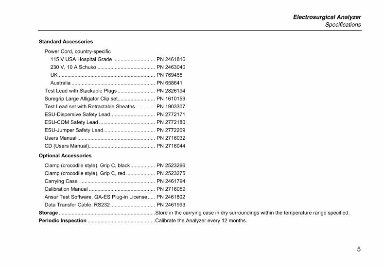
Standard Accessories
Power Cord, country-specific 115 V USA Hospital Grade ............................. PN 2461816 230 V, 10 A Schuko ........................................ PN 2463040 UK ................................................................... PN 769455 Australia .......................................................... PN 658641
Test Lead with Stackable Plugs .......................... PN 2826194 Suregrip Large Alligator Clip set.......................... PN 1610159 Test Lead set with Retractable Sheaths ............. PN 1903307 ESU-Dispersive Safety Lead............................... PN 2772171 ESU-CQM Safety Lead ....................................... PN 2772180 ESU-Jumper Safety Lead.................................... PN 2772209 Users Manual ...................................................... PN 2716032 CD (Users Manual).............................................. PN 2716044
Optional Accessories
Clamp (crocodile style), Grip C, black................. PN 2523266 Clamp (crocodile style), Grip C, red .................... PN 2523275 Carrying Case .................................................... PN 2461794 Calibration Manual .............................................. PN 2716059 Ansur Test Software, QA-ES Plug-in License..... PN 2461802 Data Transfer Cable, RS232............................... PN 2461993
Storage ...................................................................Store in the carrying case in dry surroundings within the temperature range specified. Periodic Inspection ...............................................Calibrate the Analyzer every 12 months.
QA-ES II Users Manual
6
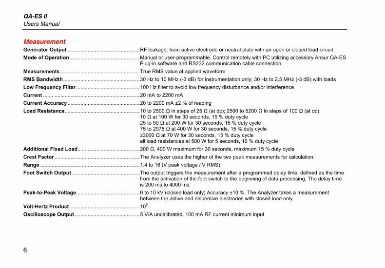
Measurement Generator Output ..................................................RF leakage: from active electrode or neutral plate with an open or closed load circuit Mode of Operation ................................................Manual or user-programmable. Control remotely with PC utilizing accessory Ansur QA-ES
Plug-in software and RS232 communication cable connection. Measurements .......................................................True RMS value of applied waveform RMS Bandwidth .....................................................30 Hz to 10 MHz (-3 dB) for instrumentation only; 30 Hz to 2.5 MHz (-3 dB) with loads Low Frequency Filter ............................................100 Hz filter to avoid low frequency disturbance and/or interference Current ...................................................................20 mA to 2200 mA Current Accuracy ..................................................20 to 2200 mA ±2 % of reading Load Resistance....................................................10 to 2500 Ω in steps of 25 Ω (at dc); 2500 to 5200 Ω in steps of 100 Ω (at dc)
10 Ω at 100 W for 30 seconds, 15 % duty cycle 25 to 50 Ω at 200 W for 30 seconds, 15 % duty cycle 75 to 2975 Ω at 400 W for 30 seconds, 15 % duty cycle ≥3000 Ω at 70 W for 30 seconds, 15 % duty cycle all load resistances at 500 W for 5 seconds, 10 % duty cycle
Additional Fixed Load...........................................200 Ω, 400 W maximum for 30 seconds, maximum 15 % duty cycle Crest Factor ...........................................................The Analyzer uses the higher of the two peak measurements for calculation. Range .....................................................................1.4 to 16 (V peak voltage / V RMS) Foot Switch Output ...............................................The output triggers the measurement after a programmed delay time, defined as the time
from the activation of the foot switch to the beginning of data processing. The delay time is 200 ms to 4000 ms.
Peak-to-Peak Voltage............................................0 to 10 kV (closed load only) Accuracy ±10 %. The Analyzer takes a measurement between the active and dispersive electrodes with closed load only.
Volt-Hertz Product.................................................109 Oscilloscope Output .............................................5 V/A uncalibrated, 100 mA RF current minimum input
Electrosurgical Analyzer Controls and Connections
7
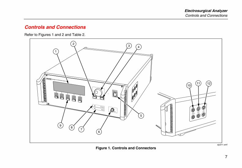
Controls and Connections Refer to Figures 1 and 2 and Table 2.
POWER
ENTER
CANCEL
RF-DETECT
REMOTESCOPE OUTPUT
F1F2
F3F4
F5
QA-ES ELECTROSURGERY ANALYZER
5
121110
32
1
98
76
4
FOOT
SWITCH
FIXED
LOAD
VAR.
LOAD
eju011.emf
Figure 1. Controls and Connectors
QA-ES II Users Manual
8
115V
13
17 1615 14
eju010.emf
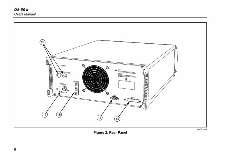
Figure 2. Rear Panel
Electrosurgical Analyzer Controls and Connections
9
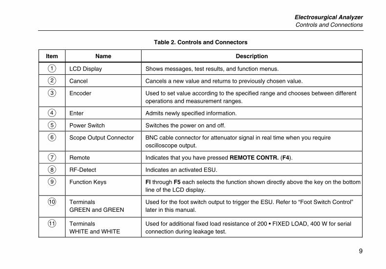
Table 2. Controls and Connectors
Item Name Description
A LCD Display Shows messages, test results, and function menus.
B Cancel Cancels a new value and returns to previously chosen value.
C Encoder Used to set value according to the specified range and chooses between different operations and measurement ranges.
D Enter Admits newly specified information.
E Power Switch Switches the power on and off.
F Scope Output Connector BNC cable connector for attenuator signal in real time when you require oscilloscope output.
G Remote Indicates that you have pressed REMOTE CONTR. (F4).
H RF-Detect Indicates an activated ESU.
I Function Keys Fl through F5 each selects the function shown directly above the key on the bottom line of the LCD display.
J Terminals GREEN and GREEN
Used for the foot switch output to trigger the ESU. Refer to “Foot Switch Control” later in this manual.
K Terminals WHITE and WHITE
Used for additional fixed load resistance of 200 • FIXED LOAD, 400 W for serial connection during leakage test.
QA-ES II Users Manual
10
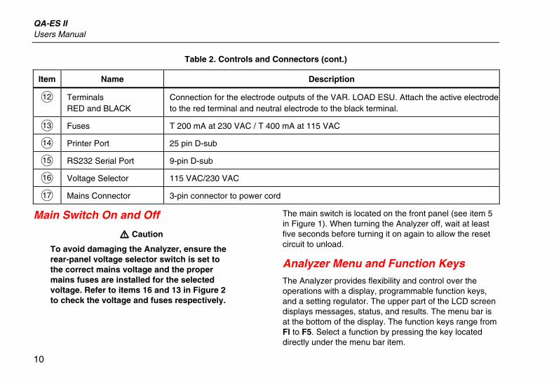
Table 2. Controls and Connectors (cont.)
Item Name Description
L Terminals RED and BLACK
Connection for the electrode outputs of the VAR. LOAD ESU. Attach the active electrode to the red terminal and neutral electrode to the black terminal.
M Fuses T 200 mA at 230 VAC / T 400 mA at 115 VAC
N Printer Port 25 pin D-sub
O RS232 Serial Port 9-pin D-sub
P Voltage Selector 115 VAC/230 VAC
Q Mains Connector 3-pin connector to power cord
Main Switch On and Off
W Caution
To avoid damaging the Analyzer, ensure the rear-panel voltage selector switch is set to the correct mains voltage and the proper mains fuses are installed for the selected voltage. Refer to items 16 and 13 in Figure 2 to check the voltage and fuses respectively.
The main switch is located on the front panel (see item 5 in Figure 1). When turning the Analyzer off, wait at least five seconds before turning it on again to allow the reset circuit to unload.
Analyzer Menu and Function Keys The Analyzer provides flexibility and control over the operations with a display, programmable function keys, and a setting regulator. The upper part of the LCD screen displays messages, status, and results. The menu bar is at the bottom of the display. The function keys range from Fl to F5. Select a function by pressing the key located directly under the menu bar item.
Electrosurgical Analyzer Analyzer Menu and Function Keys
11
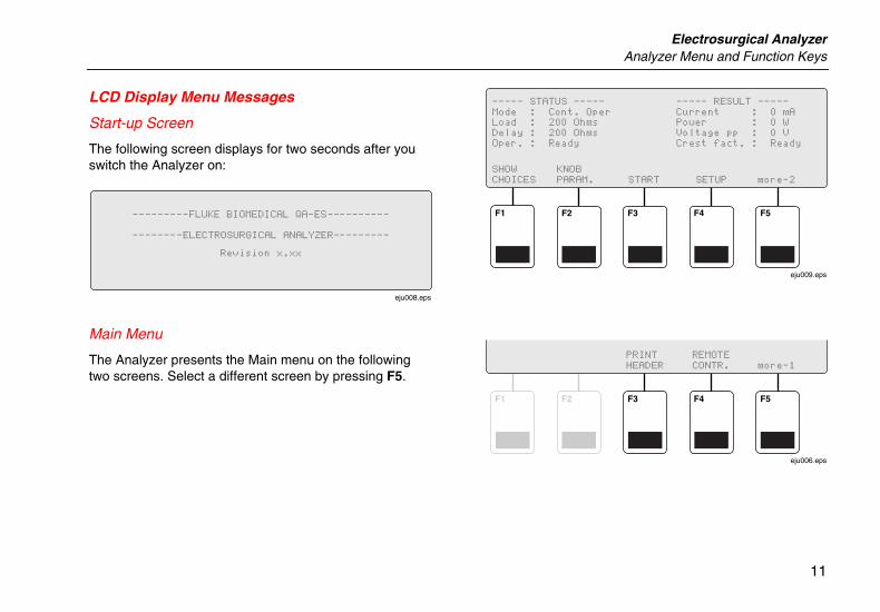
LCD Display Menu Messages
Start-up Screen
The following screen displays for two seconds after you switch the Analyzer on:
eju008.eps
Main Menu
The Analyzer presents the Main menu on the following two screens. Select a different screen by pressing F5.
F1 F2 F3 F4 F5
eju009.eps
F1 F2 F3 F4 F5
eju006.eps
QA-ES II Users Manual
12
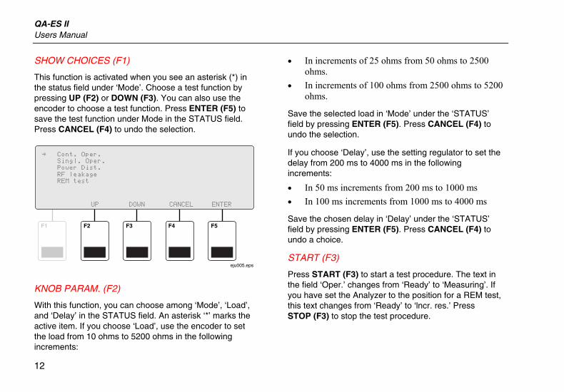
SHOW CHOICES (F1)
This function is activated when you see an asterisk (*) in the status field under ‘Mode’. Choose a test function by pressing UP (F2) or DOWN (F3). You can also use the encoder to choose a test function. Press ENTER (F5) to save the test function under Mode in the STATUS field. Press CANCEL (F4) to undo the selection.
F1 F2 F3 F4 F5
eju005.eps
KNOB PARAM. (F2)
With this function, you can choose among ‘Mode’, ‘Load’, and ‘Delay’ in the STATUS field. An asterisk ‘*’ marks the active item. If you choose ‘Load’, use the encoder to set the load from 10 ohms to 5200 ohms in the following increments:
• In increments of 25 ohms from 50 ohms to 2500 ohms.
• In increments of 100 ohms from 2500 ohms to 5200 ohms.
Save the selected load in ‘Mode’ under the ‘STATUS’ field by pressing ENTER (F5). Press CANCEL (F4) to undo the selection.
If you choose ‘Delay’, use the setting regulator to set the delay from 200 ms to 4000 ms in the following increments:
• In 50 ms increments from 200 ms to 1000 ms • In 100 ms increments from 1000 ms to 4000 ms
Save the chosen delay in ‘Delay’ under the ‘STATUS’ field by pressing ENTER (F5). Press CANCEL (F4) to undo a choice.
START (F3)
Press START (F3) to start a test procedure. The text in the field ‘Oper.’ changes from ‘Ready’ to ‘Measuring’. If you have set the Analyzer to the position for a REM test, this text changes from ‘Ready’ to ‘lncr. res.’ Press STOP (F3) to stop the test procedure.
Electrosurgical Analyzer Analyzer Menu and Function Keys
13
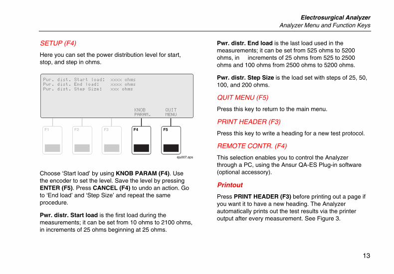
SETUP (F4)
Here you can set the power distribution level for start, stop, and step in ohms.
F1 F2 F3 F4 F5
eju007.eps
Choose ‘Start load’ by using KNOB PARAM (F4). Use the encoder to set the level. Save the level by pressing ENTER (F5). Press CANCEL (F4) to undo an action. Go to ‘End load’ and ‘Step Size’ and repeat the same procedure.
Pwr. distr. Start load is the first load during the measurements; it can be set from 10 ohms to 2100 ohms, in increments of 25 ohms beginning at 25 ohms.
Pwr. distr. End load is the last load used in the measurements; it can be set from 525 ohms to 5200 ohms, in increments of 25 ohms from 525 to 2500 ohms and 100 ohms from 2500 ohms to 5200 ohms.
Pwr. distr. Step Size is the load set with steps of 25, 50, 100, and 200 ohms.
QUIT MENU (F5)
Press this key to return to the main menu.
PRINT HEADER (F3)
Press this key to write a heading for a new test protocol.
REMOTE CONTR. (F4)
This selection enables you to control the Analyzer through a PC, using the Ansur QA-ES Plug-in software (optional accessory).
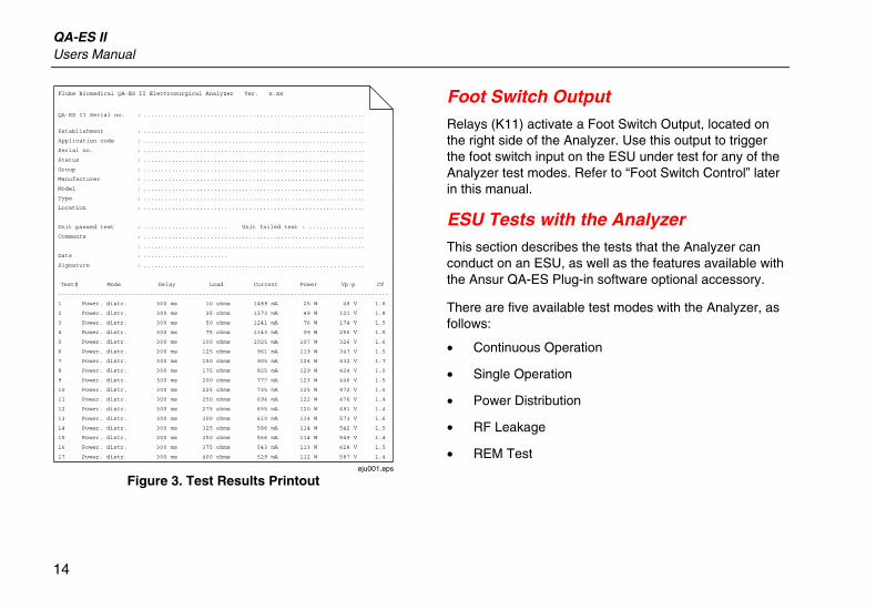
Printout
Press PRINT HEADER (F3) before printing out a page if you want it to have a new heading. The Analyzer automatically prints out the test results via the printer output after every measurement. See Figure 3.
QA-ES II Users Manual
14
eju001.eps
Figure 3. Test Results Printout
Foot Switch Output Relays (K11) activate a Foot Switch Output, located on the right side of the Analyzer. Use this output to trigger the foot switch input on the ESU under test for any of the Analyzer test modes. Refer to “Foot Switch Control” later in this manual.
ESU Tests with the Analyzer This section describes the tests that the Analyzer can conduct on an ESU, as well as the features available with the Ansur QA-ES Plug-in software optional accessory.
There are five available test modes with the Analyzer, as follows:
• Continuous Operation
• Single Operation
• Power Distribution
• RF Leakage
• REM Test
Electrosurgical Analyzer ESU Tests with the Analyzer
15
Access these tests using the following steps:
1. Press F2 until an asterisk (*) symbol appears following ‘Mode’.
2. Rotate the encoder knob until the required test mode appears on the screen, and then press the Enter key.
Power Output Tests
You can conduct power output tests with the Analyzer in the Continuous Operation, Single Operation, or Power Distribution mode. These tests check the power output characteristics of the ESU and provide output current (A), power (W), peak-to-peak voltage (V), and crest factor values.
The following standards and setup diagram apply to any of the power output test modes.
Note
Do not reduce the power output by more than that specified in IEC 601-2-2, Third edition 1998-09. The power output must be within the range specified in ANSI/AAMI HF18-2001.
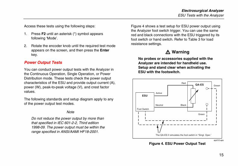
Figure 4 shows a test setup for ESU power output using the Analyzer foot switch trigger. You can use the same red and black connections with the ESU triggered by its foot switch or hand switch. Refer to Table 3 for load resistance settings.
W Warning No probes or accessories supplied with the Analyzer are intended for handheld use. Setup and stand clear when activating the ESU with the footswitch.
Foot Switch
Green
Green
Black
Red
Neutral
ActiveESU
QA-ES
The QA-ES II simulates the foot switch in "Singl. Oper.'
eju012.eps
Figure 4. ESU Power Output Test
QA-ES II Users Manual
16
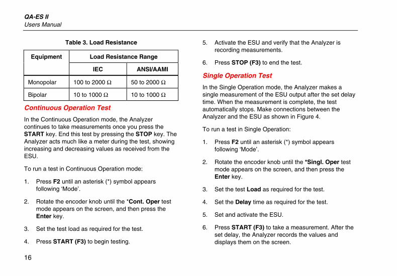
Table 3. Load Resistance
Load Resistance Range Equipment
IEC ANSI/AAMI
Monopolar 100 to 2000 Ω 50 to 2000 Ω
Bipolar 10 to 1000 Ω 10 to 1000 Ω
Continuous Operation Test
In the Continuous Operation mode, the Analyzer continues to take measurements once you press the START key. End this test by pressing the STOP key. The Analyzer acts much like a meter during the test, showing increasing and decreasing values as received from the ESU.
To run a test in Continuous Operation mode:
1. Press F2 until an asterisk (*) symbol appears following ‘Mode’.
2. Rotate the encoder knob until the *Cont. Oper test mode appears on the screen, and then press the Enter key.
3. Set the test load as required for the test.
4. Press START (F3) to begin testing.
5. Activate the ESU and verify that the Analyzer is recording measurements.
6. Press STOP (F3) to end the test.
Single Operation Test
In the Single Operation mode, the Analyzer makes a single measurement of the ESU output after the set delay time. When the measurement is complete, the test automatically stops. Make connections between the Analyzer and the ESU as shown in Figure 4.
To run a test in Single Operation:
1. Press F2 until an asterisk (*) symbol appears following ‘Mode’.
2. Rotate the encoder knob until the *Singl. Oper test mode appears on the screen, and then press the Enter key.
3. Set the test Load as required for the test.
4. Set the Delay time as required for the test.
5. Set and activate the ESU.
6. Press START (F3) to take a measurement. After the set delay, the Analyzer records the values and displays them on the screen.
Electrosurgical Analyzer ESU Tests with the Analyzer
17
7. After taking a measurement, the Analyzer resets automatically and is then ready for additional testing.
If connected to a printer, the Analyzer writes a line of test results to the printer following each Single Operation test.
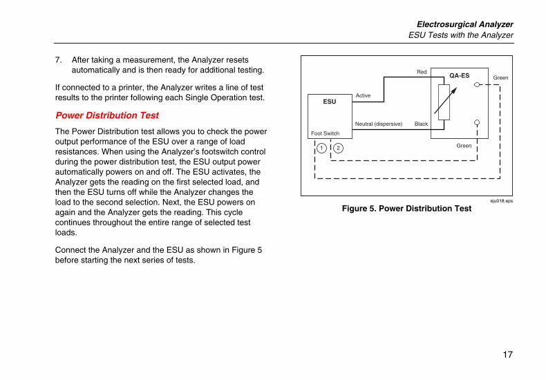
Power Distribution Test
The Power Distribution test allows you to check the power output performance of the ESU over a range of load resistances. When using the Analyzer’s footswitch control during the power distribution test, the ESU output power automatically powers on and off. The ESU activates, the Analyzer gets the reading on the first selected load, and then the ESU turns off while the Analyzer changes the load to the second selection. Next, the ESU powers on again and the Analyzer gets the reading. This cycle continues throughout the entire range of selected test loads.
Connect the Analyzer and the ESU as shown in Figure 5 before starting the next series of tests.
21
Foot Switch
Green
Green
Black
Red
Neutral (dispersive)
ActiveESU
QA-ES
eju018.eps
Figure 5. Power Distribution Test
QA-ES II Users Manual
18
To run a Power Distribution Test, perform the following steps:
1. Press F2 until an asterisk (*) symbol appears following ‘Mode’.
2. Rotate the encoder knob until the *Power Dist test mode appears on the screen, and then press the Enter key.
3. Press SETUP (F4) to access the setup menu for this test.
4. Set the Start Load, End Load, and Step Size for the test. Use the KNOB PARAM. (F3) key, the encoder knob, and the Enter key to make and confirm selections. Press QUIT MENU (F4) when set.
5. Set and activate the ESU using the Analyzer foot switch control instructions found later in this manual.
WCaution
If you cannot connect to the foot switch control, you may be able to keep the ESU activated throughout the test. However, please check with the ESU manufacturer prior to triggering for a prolonged period in this fashion; damage to the ESU could otherwise result.
6. Press START (F3) to begin the test. The Analyzer steps through the loads with a delay between each, as set in the test SETUP screen. The Analyzer displays values on the screen for each load as it steps through the test.
(If connected to a printer, the Analyzer writes a line of test results for each step in the Power Distribution Test.)
HF Current Leakage Test
This test checks whether the active and dispersive leakage currents are within acceptable limits. There are four test setups to accomplish this testing.
The ESU must operate at the maximum output setting in each operating mode per IEC 601-2-2 and ANSI/AAMI HF18-2001 specifications. The limits for the acceptable leakage currents depend upon the test configuration as shown in Table 4.
Electrosurgical Analyzer ESU Tests with the Analyzer
19
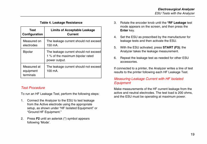
Table 4. Leakage Resistance
Test Configuration
Limits of Acceptable Leakage Current
Measured on electrodes
The leakage current should not exceed 150 mA.
Bipolar The leakage current should not exceed 1 % of the maximum bipolar rated power output.
Measured at equipment terminals
The leakage current should not exceed 100 mA.
Test Procedure
To run an HF Leakage Test, perform the following steps:
1. Connect the Analyzer to the ESU to test leakage from the Active electrode using the appropriate setup, as shown under “HF Isolated Equipment” or “Ground HF Equipment.”
2. Press F2 until an asterisk (*) symbol appears following ‘Mode’.
3. Rotate the encoder knob until the *RF Leakage test mode appears on the screen, and then press the Enter key.
4. Set the ESU as prescribed by the manufacturer for leakage tests and then activate the ESU.
5. With the ESU activated, press START (F3); the Analyzer takes the leakage measurement.
6. Repeat the leakage test as needed for other ESU accessories.
If connected to a printer, the Analyzer writes a line of test results to the printer following each HF Leakage Test.
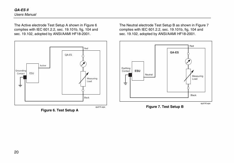
Measuring Leakage Current with HF Isolated Equipment
Make measurements of the HF current leakage from the active and neutral electrodes. The test load is 200 ohms, and the ESU must be operating at maximum power.
QA-ES II Users Manual
20
The Active electrode Test Setup A shown in Figure 6 complies with IEC 601.2.2, sec. 19.101b, fig, 104 and sec. 19.102, adopted by ANSI/AAMI HF18-2001.
eju015.eps
Figure 6. Test Setup A
The Neutral electrode Test Setup B as shown in Figure 7 complies with IEC 601.2.2, sec. 19.101b, fig, 104 and sec. 19.102, adopted by ANSI/AAMI HF18-2001.
MeasuringLoad
Black
EarthingContact
Red
Neutral
QA-ES
ESU
eju016.eps
Figure 7. Test Setup B
Electrosurgical Analyzer ESU Tests with the Analyzer
21
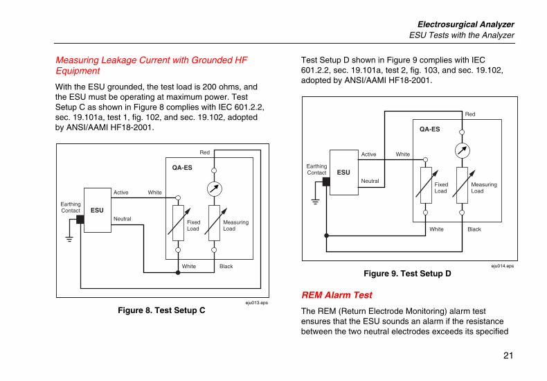
Measuring Leakage Current with Grounded HF Equipment
With the ESU grounded, the test load is 200 ohms, and the ESU must be operating at maximum power. Test Setup C as shown in Figure 8 complies with IEC 601.2.2, sec. 19.101a, test 1, fig. 102, and sec. 19.102, adopted by ANSI/AAMI HF18-2001.
White
FixedLoad
MeasuringLoad
Black
EarthingContact
Red
White
Neutral
Active
QA-ES
ESU
eju013.eps
Figure 8. Test Setup C
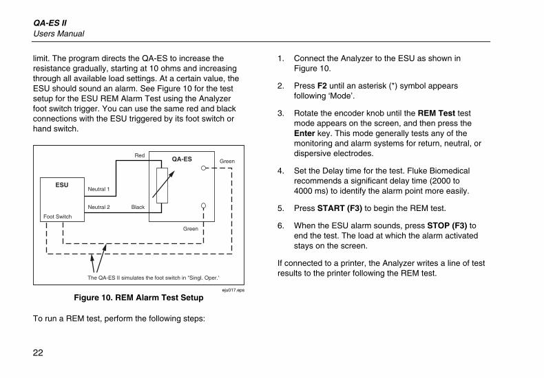
Test Setup D shown in Figure 9 complies with IEC 601.2.2, sec. 19.101a, test 2, fig. 103, and sec. 19.102, adopted by ANSI/AAMI HF18-2001.
White
FixedLoad
MeasuringLoad
Black
EarthingContact
Red
White
Neutral
Active
QA-ES
ESU
eju014.eps
Figure 9. Test Setup D
REM Alarm Test
The REM (Return Electrode Monitoring) alarm test ensures that the ESU sounds an alarm if the resistance between the two neutral electrodes exceeds its specified
QA-ES II Users Manual
22
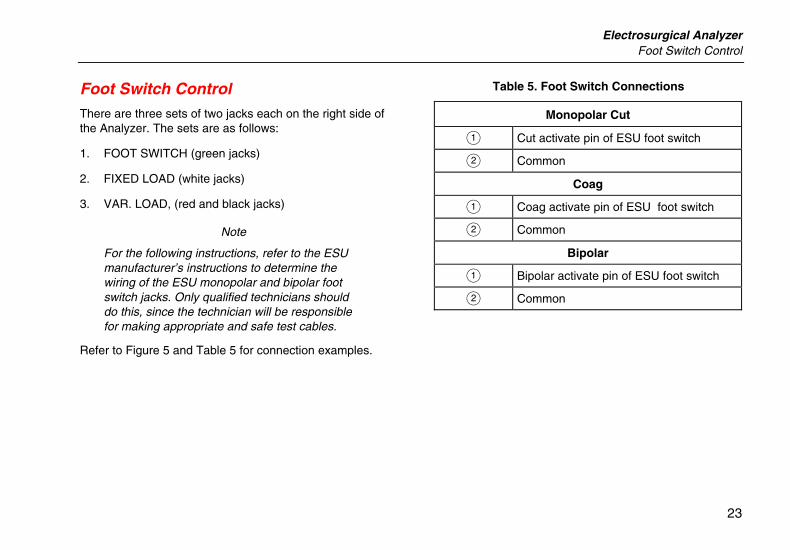
limit. The program directs the QA-ES to increase the resistance gradually, starting at 10 ohms and increasing through all available load settings. At a certain value, the ESU should sound an alarm. See Figure 10 for the test setup for the ESU REM Alarm Test using the Analyzer foot switch trigger. You can use the same red and black connections with the ESU triggered by its foot switch or hand switch.
Foot Switch
Green
Green
Black
Red
Neutral 2
Neutral 1ESU
QA-ES
The QA-ES II simulates the foot switch in "Singl. Oper.'
eju017.eps
Figure 10. REM Alarm Test Setup
To run a REM test, perform the following steps:
1. Connect the Analyzer to the ESU as shown in Figure 10.
2. Press F2 until an asterisk (*) symbol appears following ‘Mode’.
3. Rotate the encoder knob until the REM Test test mode appears on the screen, and then press the Enter key. This mode generally tests any of the monitoring and alarm systems for return, neutral, or dispersive electrodes.
4. Set the Delay time for the test. Fluke Biomedical recommends a significant delay time (2000 to 4000 ms) to identify the alarm point more easily.
5. Press START (F3) to begin the REM test.
6. When the ESU alarm sounds, press STOP (F3) to end the test. The load at which the alarm activated stays on the screen.
If connected to a printer, the Analyzer writes a line of test results to the printer following the REM test.
Electrosurgical Analyzer Foot Switch Control
23
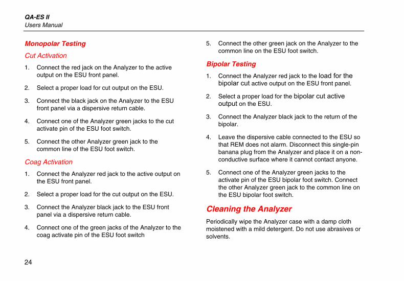
Foot Switch Control There are three sets of two jacks each on the right side of the Analyzer. The sets are as follows:
1. FOOT SWITCH (green jacks)
2. FIXED LOAD (white jacks)
3. VAR. LOAD, (red and black jacks)
Note
For the following instructions, refer to the ESU manufacturer’s instructions to determine the wiring of the ESU monopolar and bipolar foot switch jacks. Only qualified technicians should do this, since the technician will be responsible for making appropriate and safe test cables.
Refer to Figure 5 and Table 5 for connection examples.
Table 5. Foot Switch Connections
Monopolar Cut
A Cut activate pin of ESU foot switch
B Common
Coag
A Coag activate pin of ESU foot switch
B Common
Bipolar
A Bipolar activate pin of ESU foot switch
B Common
QA-ES II Users Manual
24
Monopolar Testing
Cut Activation
1. Connect the red jack on the Analyzer to the active output on the ESU front panel.
2. Select a proper load for cut output on the ESU.
3. Connect the black jack on the Analyzer to the ESU front panel via a dispersive return cable.
4. Connect one of the Analyzer green jacks to the cut activate pin of the ESU foot switch.
5. Connect the other Analyzer green jack to the common line of the ESU foot switch.
Coag Activation
1. Connect the Analyzer red jack to the active output on the ESU front panel.
2. Select a proper load for the cut output on the ESU.
3. Connect the Analyzer black jack to the ESU front panel via a dispersive return cable.
4. Connect one of the green jacks of the Analyzer to the coag activate pin of the ESU foot switch
5. Connect the other green jack on the Analyzer to the common line on the ESU foot switch.
Bipolar Testing
1. Connect the Analyzer red jack to the load for the bipolar cut active output on the ESU front panel.
2. Select a proper load for the bipolar cut active output on the ESU.
3. Connect the Analyzer black jack to the return of the bipolar.
4. Leave the dispersive cable connected to the ESU so that REM does not alarm. Disconnect this single-pin banana plug from the Analyzer and place it on a non-conductive surface where it cannot contact anyone.
5. Connect one of the Analyzer green jacks to the activate pin of the ESU bipolar foot switch. Connect the other Analyzer green jack to the common line on the ESU bipolar foot switch.
Cleaning the Analyzer Periodically wipe the Analyzer case with a damp cloth moistened with a mild detergent. Do not use abrasives or solvents.