Embed Size (px)
Citation preview
S
Ee
Ya
b
a
ARAA
KGNEE
1
sbtenotpopea[atd
mcaat
0d
Journal of Power Sources 195 (2010) 3031–3035
Contents lists available at ScienceDirect
Journal of Power Sources
journa l homepage: www.e lsev ier .com/ locate / jpowsour
hort communication
lectrophoretic deposition of graphene nanosheets on nickel foams forlectrochemical capacitors
ao Chena,b, Xiong Zhanga, Peng Yua,b, Yanwei Maa,∗
Institute of Electrical Engineering, Chinese Academy of Sciences, Beijing 100190, People’s Republic of ChinaGraduate University of Chinese Academy Sciences, Beijing 100049, People’s Republic of China
r t i c l e i n f o
rticle history:eceived 31 August 2009
a b s t r a c t
Graphene nanosheets are deposited on nickel foams with 3D porous structure by an electrophoreticdeposition method using the colloids of graphene monolayers in ethanol as electrolytes. The high
ccepted 13 November 2009vailable online 18 November 2009
eywords:raphene nanosheetsickel foamslectrochemical capacitors
specific capacitance of 164 F g−1 is obtained from cyclic voltammetry measurement at a scan rate of10 mV s−1. When the current densities are set as 3 and 6 A g−1, the specific capacitance values stillreach 139 and 100 F g−1, respectively. The high capacitance is attributed to nitrogen atoms in oxida-tion product of p-phenylene diamine (OPPD) adsorbed on the surface of the graphene nanosheets. Thecomparable results suggest potential application to electrochemical capacitors based on the graphenenanosheets.
lectrophoretic deposition
. Introduction
Electrochemical capacitors (ECs) are excellent electrical energytorage devices, exhibiting higher power density than rechargeableatteries and much greater capacitance than traditional dielec-ric capacitors [1]. With the unique advantages, ECs can be usedither as the primary power sources independently or in combi-ation with secondary cells to complement the low power densityf them. Typically, they have great promise for potential applica-ions such as mobile electronics, transportation, renewable energyroduction and aerospace systems [2]. Energy storage mechanismsf ECs are divided into two ways: double-layer capacitance andseudocapacitance [3]. Commonly, porous carbon materials are thelectrodes of double-layer capacitors, while transition metal oxidesnd conducting polymers are corresponding to pseudocapacitors4]. Comparing with pseudocapacitors, more life time, lower costnd higher power density can be attained for double-layer capaci-ors. Hence carbonaceous materials with high specific area are theeveloped electrodes for ECs [5].
Graphene, which is discovered by Geim in 2004, is a 2D flataterial consisting of monolayer carbon atoms [6]. As a new
arbonaceous material, graphene has evident advantages for thepplications in ECs because of its large theoretic specific surfacerea (2600 m2 g−1) and high room temperature electrical conduc-ivity. Unlike activated carbon [7], the effective surface area of
∗ Corresponding author at: Tel.: +86 10 82547129; fax: +86 10 82547137.E-mail address: [email protected] (Y. Ma).
378-7753/$ – see front matter © 2009 Elsevier B.V. All rights reserved.oi:10.1016/j.jpowsour.2009.11.057
© 2009 Elsevier B.V. All rights reserved.
graphene does not depend on the distribution of pores but layers.Moreover the resistance of graphene is much smaller than that ofactivated carbon. Therefore graphene, especially chemically modi-fied graphene which is prone to being produced on a large scale [8],is one of the most promising carbon materials to be applied to ECs.Recently, Vivekchand et al. [9] reported on graphene-based ECs,electrodes of which were prepared by thermal exfoliation, with thespecific capacitance of 117 F g−1. Stoller et al. [10] and Wang et al.[11] obtained the specific capacitance of 135 and 205 F g−1 at thecurrent densities of 1.3 and 0.1 A g−1 by reducing graphite oxidewith liquid and gas hydrazine hydrate, respectively.
In the process of fabricating electrodes, the choices of the cur-rent collectors and methods of depositing activated materials onthem are the most crucial element to affect the performance ofECs. As one of the most economical and versatile methods fordepositing films and coatings, electrophoretic deposition (EPD)enables the formation of high purity deposits of uniform thick-ness on substrates with complex shape [12,13]. With high demandon high surface area current collectors in ECs, porous nickel foamshave particular advantages, such as 3D web containing the highaccessible activated materials and better electrolytes access toactivated materials to improve the electrochemical performance[14,15].
More recently, another strategy of preparing graphene and
graphene films has been exploited by our group. We have fabri-cated the stable graphene colloids by reducing exfoliated graphiteoxide with p-phenylene diamine [16]. Considering the graphenenanosheets are positively charged due to adsorbing the oxidationproduct of p-phenylene diamine (OPPD) with –N+, we devel-
3032 Y. Chen et al. / Journal of Power Sou
oao1
2
aawa0fcces4
gfioJaotea−cpes
3
e
Fig. 1. TEM image of graphene nanosheets dispersed in ethanol.
ped the EPD method to deposit graphene on the nickel foamss electrodes of ECs. The high specific capacitance of 164 F g−1 isbtained from cyclic voltammetry measurement at a scan rate of0 mV s−1.
. Experimental
Stable graphene colloids modified by OPPD were synthesizedccording to the literature [16]. The as-made graphene was filterednd washed with acetone. Then the washed graphene powdersere transferred into ethanol to form stable graphene colloids
fter mild ultrasonication with an approximate concentration of.1 mg mL−1. The course of the EPD was as follows: a piece of nickeloam was used as the negative electrode and indium tin oxide (ITO)-oated conductive glass as the positive electrode; the grapheneolloids in ethanol were electrolyte. The distance between the twolectrodes was 1 cm and the applied voltage was 50 V. After depo-ition, the graphene sheets on the nickel foams were annealed at00 ◦C for 3 h under the flow of Ar.
The transmission electron microscopy (TEM) images ofraphene colloids were investigated by JEOL JSM 2010. Theeld emission scanning electron microscopy (FESEM) imagesf the nickel foams before and after EPD were observed byEOL JSM 6700F. The electrode performance was measured in
beaker-type electrochemical cell with the graphene sheetsn nickel foam after deposition and annealing as a work elec-rode, a platinum counter electrode and a standard Hg/HgOlectrode as a reference one. The electrolyte was 6 M KOHqueous solution. Cyclic voltammetry scans were recorded from0.8 to 0 V (vs. Hg/HgO) at different scan rates. Galvanostatic
harge/discharge cycling in the potential range of −0.6 to 0 V waserformed at different constant current densities. Both the twolectrochemical methods were carried out with CHI 660C work-tation.
. Results and discussion
In our previous studies, colloids of graphene monolayers inthanol had been demonstrated by atomic force microscope (AFM)
rces 195 (2010) 3031–3035
and X-ray photoelectron spectroscope (XPS) [16]. Fig. 1 shows theTEM images of graphene sheets dispersed in ethanol. The nanoscalegraphene sheets are very thin with some black dots, which havebeen confirmed to be OPPD, covering on the surface of the graphenesheets. It is found that the stable graphene colloids can remainfor a long time. Obviously, the residual OPPD is a good dispersantfor graphene. Moreover, it made graphene nanosheets positivelycharged, being convenient for the applications of EPD. ITO-coatedglass was used as the substrate on which graphene nanosheetswere deposited by EPD [16]. However, the conductivity of ITO issmall and the graphene may be exfoliated from the ITO in the elec-trolyte under the electrochemical reactions. So porous nickel foamsare much more suitable than ITOs as current collectors. Fig. 2bshows the morphology of the graphene nanosheets deposited onthe nickel foam, comparing with that of bare nickel foam with a 3Dcross-linked grid structure (Fig. 2a). There is no obvious differencebetween them via low magnification FESEM views. Thus middleand high magnification images need to be studied. There are blackcoatings on the nickel foam treated by EPD in Fig. 2d, while nothingcan be observed on the bare nickel foam (Fig. 2c). In Fig. 2e, blackgraphene nanosheets on the white nickel substrate can be observedfrom the high magnification image. Evidently, some corrugationand scrolling are clear on the surface of the graphene coatings,suggesting that some graphene nanosheets may aggregate afterEPD. The thin and flat coatings may correspond to few layers ofgraphene.
Fig. 3 shows the cyclic voltammetry (CV) profiles of the graphenenanosheets electrode at different scan rates and a bare nickel foamat 10 mV s−1 in a potential range between −0.8 and 0 V. In thecase of 100 mV s−1, a nonrectangular shape was observed. Clearlyenhanced capacitance can be attributed to adsorption/desorptionof positively charged ions in negative potentials. Considering thatthe graphene contained 10% of nitrogen according to the preve-nient XPS result, the deviation from the imaginary rectangle maybe caused by pseudocapacitive effects between potassium cationsand the nitrogen atoms of graphene [17]. While the CV of thebare nickel foam at 10 mV s−1 is negligible when compared withthe graphene nanosheets electrode at the same condition. Thespecific capacitance of the graphene nanosheets electrode is cal-culated using the integrated area of charge curve which is moreaccurate than the half one of the full CV curve. Concretely, theformer, which is smaller than the latter, is obtained based onEq. (1):
C = 1�V · m · s
∫ 0 V
−0.8 V
|i|dV (1)
where �V is the potential window, m is the mass of the graphenenanosheets, s is the scan rate, i is the instantaneous charge currentin given potential. In order to expel the contribution of nickel foamto the specific capacitance, integrated area of curve (d) in Fig. 3should be subtracted. The specific capacitance values at 10 mV s−1
before and after subtracting that of the bare nickel foam are both164 F g−1. So the CV curves of the graphene nanosheets electrodereflect the behavior of the graphene nanosheets without the effectof nickel.
The capacitance retention ratio of the graphene, 60% at100 mV s−1 which corresponds to 97 F g−1, is shown in Fig. 4. Also,the retention ratios of it at 20 and 50 mV s−1 are 89 and 73%, respec-tively. The ratio is smaller than other reports [10,18] due to lownormal conductivity [19] of the graphene nanosheets absorbing
OPPD. In addition, graphene sheets have no pores to provide a shortion-transport pathway in normal plane so that an electric doublelayer can only form at the surface of it in a short time, which maydecrease the retention ratio of the graphene nanosheets electrode.The cycle performance of the graphene nanosheets electrode was
Y. Chen et al. / Journal of Power Sources 195 (2010) 3031–3035 3033
(b), (d
esFiAm
cc
Fig. 2. FESEM images of (a) and (c) bare nickel foam and
lucidated by CV. From Fig. 5, it is noticed that repetitive mea-urements at 5 mV s−1 result in charged specific capacitance loss.ig. 6 exhibits the cycle life data of the graphene nanosheets. Withncreasing the cycle numbers, the specific capacitance decreases.
fter 700 cycles, the specific capacitance remains 61% of the maxi-um capacitance.Fig. 7 shows the results of galvanostatic charge/dischargeycling at high current densities of 3 and 6 A g−1. The specificapacitance values are 139 and 100 F g−1, respectively. The high
) and (e) graphene nanosheets deposited on nickel foam.
specific capacitance even at a relative high current density may beattributed to the nitrogen atoms of OPPD doped in graphene matrix[20]. The chargeable nitrogen at the periphery of the graphenelayers can adsorb more charges from the electrolyte and improve
the charge-exchange characteristics of carbon [21]. The modifica-tion of surface polarity of graphene nanosheets with nitrogen cannot only strengthen the wettability of the interface between elec-trode and electrolyte, but also introduce pseudocapacitive effects[22,23].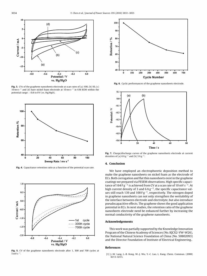
3034 Y. Chen et al. / Journal of Power Sources 195 (2010) 3031–3035
Fig. 3. CVs of the graphene nanosheets electrode at scan rates of (a) 100, (b) 50, (c)10 mv s−1 and (d) bare nickel foam electrode at 10 mv s−1 in 6 M KOH within thepotential range: −0.8 to 0 V (vs. Hg/HgO).
Fig. 4. Capacitance retention ratio as a function of the potential scan rate.
Fig. 5. CV of the graphene nanosheets electrode after 1, 300 and 700 cycles at5 mV s−1.
Fig. 6. Cyclic performances of the graphene nanosheets electrode.
Fig. 7. Charge/discharge curves of the graphene nanosheets electrode at currentdensities of (a) 6 A g−1 and (b) 3 A g−1.
4. Conclusion
We have employed an electrophoretic deposition method tomake the graphene nanosheets on nickel foam as the electrode ofECs. Both corrugation and flat thin nanosheets exist in the graphenecoatings we prepared via FESEM observations. High specific capaci-tance of 164 F g−1 is achieved from CV at a scan rate of 10 mV s−1. Athigh current density of 3 and 6 A g−1, the specific capacitance val-ues still reach 139 and 100 F g−1, respectively. The nitrogen dopedin graphene nanosheets can not only strengthen the wettability ofthe interface between electrode and electrolyte, but also introducepseudocapacitive effects. The graphene shows the good applicationpotential in ECs. In next studies, the retention ratio of the graphenenanosheets electrode need be enhanced further by increasing thenormal conductivity of the graphene nanosheets.
Acknowledgements
This work was partially supported by the Knowledge InnovationProgram of the Chinese Academy of Sciences (No. KJCX2-YW-W26),the National Natural Science Foundation of China (No. 50802093)and the Director Foundation of Institute of Electrical Engineering..
References
[1] J.-W. Lang, L.-B. Kong, W.-J. Wu, Y.-C. Luo, L. Kang, Chem. Commun. (2008)4213–4215.

er Sou
[[
[
[
[[[[[
[
Y. Chen et al. / Journal of Pow
[2] P. Simon, Y. Gogotsi, Nat. Mater. 7 (2008) 845–854.[3] K.-W. Nam, K.-B. Kim, J. Electrochem. Soc. 149 (2002) A346–A354.[4] A.G. Pandolfo, A.F. Hollenkamp, J. Power Sources 157 (2006) 11–27.[5] D. Yuan, J. Chen, J. Zeng, S. Tan, Electrochem. Commun. 10 (2008) 1067–1070.[6] K.S. Novoselov, A.K. Geim, S.V. Morozov, D. Jiang, Y. Zhang, S.V. Dubonos, I.V.
Grigorieva, A.A. Firsov, Science 306 (2004) 666–669.[7] G. Lota, T.A. Centeno, E. Frackowiak, F. Stoeckli, Electrochim. Acta 53 (2008)
2210–2216.[8] M. Choucair, P. Thordarson, J.A. Stride, Nat. Nanotechnol. 4 (2009).[9] S.R.C. Vivekchand, C.S. Rout, K.S. Subrahmanyam, A. Govindaraj, C.N.R. Rao, J.
Chem. Sci. 120 (2008) 9–13.10] M.D. Stoller, S. Park, Y. Zhu, J. An, R.S. Ruoff, Nano Lett. 8 (2008) 3498–3502.11] Y. Wang, Z. Shi, Y. Huang, Y. Ma, C. Wang, M. Chen, Y. Chen, J. Phys. Chem. C
113 (2009) 13103–13107.12] Z.-S. Wu, S. Pei, W. Ren, D. Tang, L. Gao, B. Liu, F. Li, C. Liu, H.-M. Cheng, Adv.
Mater. 21 (2009) 1756–1760.
[[
[[
rces 195 (2010) 3031–3035 3035
13] X. Fan, W. Peng, Y. Li, X. Li, S. Wang, G. Zhang, F. Zhang, Adv. Mater. 20 (2008)4490–4493.
14] J. Li, Q.M. Yang, I. Zhitomirskya, J. Power Sources 185 (2008) 1569–1574.15] G.-W. Yang, C.-L. Xu, H.-L. Li, Chem. Commun. (2008) 6537–6539.16] Y. Chen, X. Zhang, P. Yu, Y. Ma, Chem. Commun. (2009) 4527–4529.17] D. Hulicova, M. Kodama, H. Hatori, Chem. Mater. 18 (2006) 2318–2326.18] D.-W. Wang, F. Li, M. Liu, G.Q. Lu, H.-M. Cheng, Angew. Chem. Int. Ed. 47 (2008)
373–376.19] C.-W. Huang, C.-M. Chuang, J.-M. Ting, H. Teng, J. Power Sources 183 (2008)
406–410.
20] W. Kim, J.B. Joo, N. Kim, S. Oh, P. Kim, J. Yi, Carbon 47 (2009) 1407–1411.21] N.D. Kim, W. Kim, J.B. Joo, S. Oh, P. Kim, Y. Kim, J. Yi, J. Power Sources 180 (2008)671–675.22] H. Guo, Q. Gao, J. Power Sources 186 (2009) 551–556.23] W. Li, D. Chen, Z. Li, Y. Shi, Y. Wan, J. Huang, J. Yang, D. Zhao, Z. Jiang, Electrochem.
Commun. 9 (2007) 569–573.

![Nitrogen-doped carbon nanosheets from polyurethane foams ...carbonlett.org/Upload/files/CARBONLETT/[060-069]-07.pdf · Nitrogen-doped carbon nanosheets from polyurethane foams and](https://img.dokumen.tips/doc/110x75/5b6d7e8f7f8b9a3b388cf74e/nitrogen-doped-carbon-nanosheets-from-polyurethane-foams-060-069-07pdf.jpg)