Embed Size (px)
Citation preview
CERN Summer Student Lectures 2001Particle Detectors Christian Joram VI /1
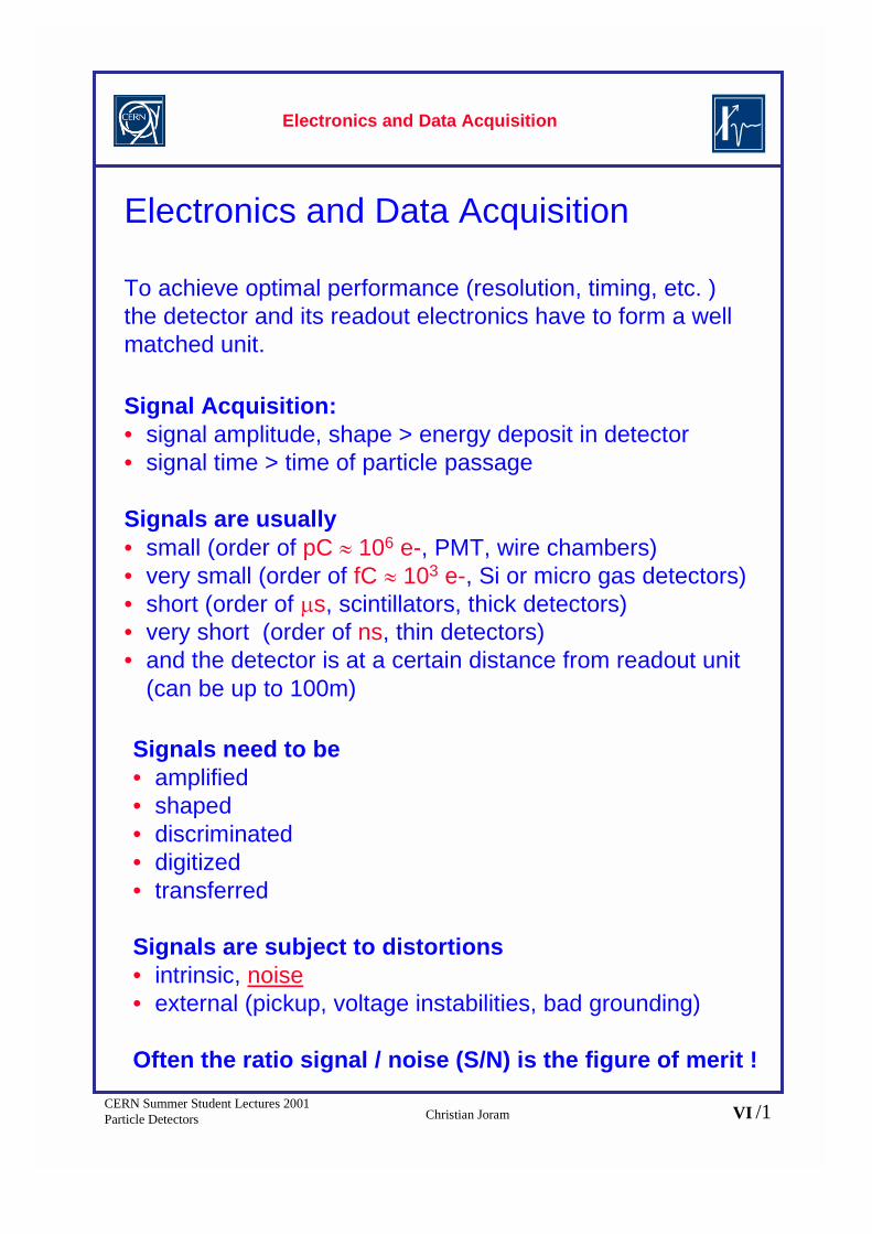
Signal Acquisition:• signal amplitude, shape > energy deposit in detector• signal time > time of particle passage
Signals are usually• small (order of pC � 106 e-, PMT, wire chambers)• very small (order of fC � 103 e-, Si or micro gas detectors)• short (order of �s, scintillators, thick detectors)• very short (order of ns, thin detectors)• and the detector is at a certain distance from readout unit
(can be up to 100m)
Electronics and Data Acquisition
To achieve optimal performance (resolution, timing, etc. )the detector and its readout electronics have to form a wellmatched unit.
Signals need to be • amplified• shaped• discriminated• digitized• transferred
Signals are subject to distortions• intrinsic, noise• external (pickup, voltage instabilities, bad grounding)
Often the ratio signal / noise (S/N) is the figure of merit !
Electronics and Data Acquisition

CERN Summer Student Lectures 2001Particle Detectors Christian Joram VI /2
Cdet.
Qi
vi
Cf
Amplification of signalsTo be independent of signal shape often charge sensitiveamplifiers are used:
vo
Qf
•Voltage gain A = -dV0/dVi•Qf = Qi because Zi= ����•Effective input capacitance Ci = Qi/vi = Cf(A+1)•Gain AQ = dV0/dQi = A/Ci =A/(A+1)/Cf ���� 1/Cf
•A certain fraction of the charge stays on the detector andwill not be detected: Qi/Qdet. = (1+Cdet/Ci)-1
•Ci must be >> Cdet.
•An amplifier is automatically also a shaper
•Every detector needs its properly designed amplifier.
Helmuth SpielerLBNL
inverting voltageamplifier
input
time time
output v0(1-e-t/�)
��������= CD/��������Cf
Zi=�
Electronics and Data Acquisition
Qdet.

CERN Summer Student Lectures 2001Particle Detectors Christian Joram VI /3
Noise
i
L22
2��
���
���
�
���
�� dn
levdv
lnedi
lnevi � current i through
a sample
current fluctuations di due to• velocity fluctuations dv • number fluctuations dn
• dv � thermal noise • dn � shot noise, 1/f noise
Shaping of signals
dte ��ite ��
�1
CR RC
Electronics and Data Acquisition

CERN Summer Student Lectures 2001Particle Detectors Christian Joram VI /4
Very useful quantity for characterization of systems:
the equivalent noise charge ENC
Fv and Fi are numerical factors depending on the details of the noisefiltering in the filtering network.
���� (ns) peaking time of the shaper
Ci (pF) total input capacitance both from detector and amplifier
vn(nV/����Hz), in(pA/����Hz) equivalent spectral current / voltage noisedensities
τinFiτCivnF vENC �������
1
t
Signal amplitude
V / I
0 Integrated charge Q
1 event many eventsNev
noise
signal
Noise israndom� Gaussianchargedistribution,centeredaround 0.
signal
noise
22 / ENCQn eQ �
�
Qn
ENC
ENCQNS signal // �
Electronics and Data Acquisition

CERN Summer Student Lectures 2001Particle Detectors Christian Joram VI /5
input
threshold
output
Some other frequently used elements
• Discriminator
• Analog-to-Digital Converter (ADC)
input
gate
capacitorcharging run down
� scaler � 001100101
• similarly: Time-to-Digital Converter (TDC)
Electronics and Data Acquisition
t
t
t
t
toscillator

CERN Summer Student Lectures 2001Particle Detectors Christian Joram VI /6
Electronics systems: Some design issues
Technology (Bipolar, CMOS,...) Noise
typ. � 1000e- ENC
Cost
Power consumptionfew mW / channel
Dynamic range
Speed (peaking time)LHC � 25 ns
Radiation hardnessLHC � dose � 100 kGy
Mode (Analog / Binary)
Robustness
• Some parameters are conflicting, e.g. speed � powerconsumption or analog mode � cost.
• Every subdetector (Si-tracker, e.m. or hadroncalorimeter, muon system, etc.) will weight constraintsdifferently.
Electronics and Data Acquisition

CERN Summer Student Lectures 2001Particle Detectors Christian Joram VI /7
Overview of an acquisition front end
• CMS inner tracker electronics
APV6 chip (128channels)
�peak = 50 ns
needs to work in de-convolution mode todetermine bunchcrossingunambiguously.
Front End Modulemounted on detector
ca. 1
00m
Peak mode Deconvolution mode
Electronics and Data Acquisition
CERN Summer Student Lectures 2001Particle Detectors Christian Joram VI /8
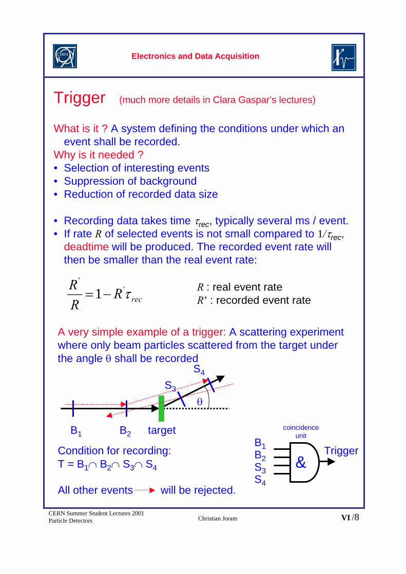
Trigger (much more details in Clara Gaspar’s lectures)
What is it ? A system defining the conditions under which anevent shall be recorded.
Why is it needed ?• Selection of interesting events• Suppression of background• Reduction of recorded data size
• Recording data takes time �rec, typically several ms / event.• If rate R of selected events is not small compared to 1/�rec,
deadtime will be produced. The recorded event rate willthen be smaller than the real event rate:
A very simple example of a trigger: A scattering experimentwhere only beam particles scattered from the target underthe angle � shall be recorded
�
B1 B2
S3
S4
Condition for recording: T = B1� B2� S3� S4
All other events will be rejected.
target
recRRR
�'
'
1��
R : real event rateR’ : recorded event rate
coincidenceunit
B1B2S3S4
Trigger&
Electronics and Data Acquisition

CERN Summer Student Lectures 2001Particle Detectors Christian Joram VI /9
In modern experiments, trigger systems must be much moreselective.
LHC
Interaction rate:~ 109 events/secondAn experiment canrecord~ 100 events/second(event size 1 MB)
�� necessarytrigger rejection ~ 107
“interesting” eventrate (H, t, Susy):very few events/sec.
For L = 1033
event data physics channeldetector parameters
Trigger = f ( )
Electronics and Data Acquisition (backup)

CERN Summer Student Lectures 2001Particle Detectors Christian Joram VI /10
10-7 s
10-6 s
10-3 s
10-1 s
Level-1 trigger: coarse selectionof interesting candidate eventswithin a few �s. L1-riggeroutput rate � 100 kHzImplementation: specifichardware (ASICS, FPGA, DSP)
Level-2 trigger: refinement ofselection criteria within � 1 ms.L2 output rate: � 1 kHzImplementation: fast processorfarms.
Level-3 trigger: identification ofthe physical process. Writingdata to storage medium.L3- output rate: 10 - 100 HzEvent size: � 1 Mbyte.Implementation: fast processorfarms.
Trigger decision is taken on several (usually 3) levels.Increasing complexity and selectivity.
All data of previous level has to be stored until subsequenttrigger decision has been taken.
Level “0”: Event rate: 109 Hz. Detector channels: 107 - 108
DAQ is running constantly at 40 MHz. Data flow � 1016 bit/sec
Electronics and Data Acquisition (backup)

CERN Summer Student Lectures 2001Particle Detectors Christian Joram VI /11
Example: ATLAS level-1 trigger
The L1 trigger is deadtimeless. The trigger decision must betaken every 25 ns!During the trigger latency time the data of each singledetector channel must be stored in pipelines of 128 cellslength.
Dec
isio
n ta
kes
abou
t 3 �
s
�la
tenc
y
Trigger logic
…...readout
unit
Electronics and Data Acquisition (backup)

CERN Summer Student Lectures 2001Particle Detectors Christian Joram VI /12
Detector Systems
Remember: we want to have info on...
• number of particles• event topology• momentum / energy• particle identity
Can’t be achievedwith a single detector !
� integrate detectors to detector systems
Geometrical concepts
Fix target geometry Collider Geometry
“Magnet spectrometer” “4 Multi purpose detector”
N
S
beam magnet calorimeter (dipole)
traget tracking muon filter
• Limited solid angle d coverage• rel. easy access (cables,
maintenance)
• “full” d coverage• very restricted access
barrel endcap endcap
Detector Systems

CERN Summer Student Lectures 2001Particle Detectors Christian Joram VI /13
collider geometry cont.
Magnetic field configurations:
Imagnet
B
coil
solenoid
+ Large homogenous fieldinside coil
- weak opposite field inreturn yoke
- Size limited (cost)- rel. high material budget
Examples:• DELPHI (SC, 1.2T)• L3 (NC, 0.5T)• CMS (SC, 4T)
toroid
Imagnet
B
+ Rel. large fields over largevolume
+ Rel. low material budget- non-uniform field- complex structure
Example:• ATLAS (Barrel air
toroid, SC, 0.6T)
Detector Systems

CERN Summer Student Lectures 2001Particle Detectors Christian Joram VI /14
Typical arrangement of subdetectors
vertex location (Si detectors) �
main tracking (gas or Si detectors) �
particle identification �e.m. calorimetry �
magnet coil �hadron calorimetry / return yoke �
muon identification / tracking �
Low de
nsity
�
high
dens
ity
high p
recis
ion �
low
prec
ision
high g
ranu
larity
� lo
w gran
ularity
track
dens
ity �
1/r2
ATLAS and CMS require high precision tracking also for highenergetic muons � large muon systems with high spatialresolution behind calorimeters.
e-
�
�+
p
Detector Systems

CERN Summer Student Lectures 2001Particle Detectors Christian Joram VI /15
Some practical considerations before building a detector
Find compromises and clever solutions …
• Mechanical stability, precision � distortion of resolution(due multiple scattering, conversion of gammas)
• Hermeticity � routing of cables and pipes• Hermeticity � thermal stability• Hermeticity � accessibility, maintainability• Compatibility with radiation
… and always keep an eye on cost
��
���
��
��
strainstressmodulus sYoung'
//]N/m[ 2
LLAFE
Composites arevery interestingcandidates,e.g. glass orcarbon fiberreinforced epoxymaterials.
Detector Systems

CERN Summer Student Lectures 2001Particle Detectors Christian Joram VI /16
Radiation damage to materials
no damage
moderate damage
destruction
Radiation levels in CMS Inner Tracker (0 < z < 280 cm)
H. Schönbacher, M. Tavlet, CERN 94-07
(=J/Kg)
Detector Systems

CERN Summer Student Lectures 2001Particle Detectors Christian Joram VI /17
Detector Systems

CERN Summer Student Lectures 2001Particle Detectors Christian Joram VI /18
Detector Systems

CERN Summer Student Lectures 2001Particle Detectors Christian Joram VI /19
Detector Systems

CERN Summer Student Lectures 2001Particle Detectors Christian Joram VI /20
Detector Systems
CERN Summer Student Lectures 2001Particle Detectors Christian Joram VI /21
Detector Exhibitionmore or less confirmed…
• GEM, Compass geometry, Bernhard Ketzer• NA49 (G. Fischer, absent until beginning of July)• HARP TPC, Lucie Linssen• ALICE RICH, Paolo Martinengo• ALICE TPC, Tom Meyer• LHCb Velo, Paula Collins• HPD (Christian Hansen)• RPC (C. Williams)• LHCb RICH Aerogel (Marco Musy) • ATLAS TRT (Hans Danielson)• CMS inner tracker mechanics (Hans Danielson)• MEDIPIX (Bettina Mikulec)• Paul trap (Christian Regenfuss)
Wishlist
• ATLAS ECAL (P. Fassnacht)• ATLAS muon, MDT (G. Mikenberg)• CMS ECAL (PbWO4 -> Ph. Bloch, P. Lecoq.)• CMS HCAL (scint. Tile -> D. Greem, A. Ferrando)