Embed Size (px)
Citation preview

12CDC110004C0201
Ele
ctro
nic
timer
s
Content
Benefits and advantages of the CT-ranges .......................................................................... 2
Selection and ordering details
CT-S range ........................................................................................................................... 4
CT-E range ........................................................................................................................... 6
CT-D range ........................................................................................................................... 8
C56xx range ......................................................................................................................... 9
Accessories C56xx range ..................................................................................................... 9
Function diagrams
CT-S range ........................................................................................................................... 10
CT-E range ........................................................................................................................... 12
CT-D range ........................................................................................................................... 14
C56xx range ......................................................................................................................... 15
Technical data, standards, load limit curves
CT-S range ........................................................................................................................... 16
CT-E range ........................................................................................................................... 18
CT-D range ........................................................................................................................... 20
C56xx range ......................................................................................................................... 22
Wiring diagrams, position of terminals, dimensional drawings
CT-S range ........................................................................................................................... 23
CT-E range ........................................................................................................................... 24
CT-D range ........................................................................................................................... 24
C56xx range ......................................................................................................................... 26
Accessories CT-S range ....................................................................................................... 27
Conversion table C56xx R CT-S/CT-E ................................................................................ 28
Electronic timers
CT-ranges

22CDC110004C0201
Ele
ctro
nic
timer
s
ab
CT-MFS CT-ERS
CT-MFE CT-ERE
e
d
c
e
a
b
c
d
1SV
C 1
10 0
00 F
050
0
1SV
C 1
10 0
00 F
050
3
1SV
C 1
10 0
00 F
050
1
1SV
C 1
10 0
00 F
050
4
1SV
C 1
10 0
00 F
049
2
1SV
C 1
10 0
00 F
051
0
1SV
C 1
10 0
00 F
051
1
1SV
C 1
10 0
00 F
049
7
1SV
C 1
10 0
00 F
050
7
1SV
C 1
10 0
00 F
049
9
1SV
C 1
10 0
00 F
049
8
1SV
C 1
10 0
00 F
050
8
1SV
C 1
10 0
00 F
050
6
Electronic timers CT-S, CT-E rangeBenefits and advantages
Electronic timers CT-S range
Electronic timers CT-E range
Time range preselection and fine adjustment
Multicolor scales allow the direct selection ofthe time range, scaled for the adjustmentpotentiometer.
Display of operational states
All actual operational states are displayed byfront-face LEDs, thus simplifying installation.
Double-chamber cage connecting terminals
Double-chamber cage connecting terminalsprovide connection of up to two wires to 2x2.5mm2
(2x14AWG), solid or stranded, with or withoutwire end ferrules.Potential distribution does not require additionalterminations, thus saving time and money.Wiring is considerably simplified through integratedcable guides.
Characteristics of CT-S range
3 multifunction and 21 multi-range timersContinuous supply voltage range (24-240VAC/DC)or multisupply voltage ranges (12-40VAC/12-60V/DC;24V, 42-48VAC/DC; 110-240VAC; 380-440VAC)1 or 2c/o contacts (250V/4A)2nd c/o contact can be selected as instantaneous contact(front-face selection switch)Timing function is initiated via external, voltage free controlcontacts or via supply voltageRemote potentiometer connection featureTime stop function is possible via external control contactIn compliance with internationalstandards and approvals , ,
Integrated markers
Integrated markers allow the product to bemarked quickly and simply. No additionalmarking labels are required.
Sealable transparent covers
Protection against unauthorized change of timevalues (available as an accessory).
Characteristics of CT-E range
12 single function timers and 2 multifunction timers(24-240VAC/DC)Single or dual supply voltage ranges24VAC/DC, 110-130VAC, 220-240VACOutput contacts – 1c/o contact (250V/4A) or solid-state output forhigh switching frequencies (thyristor 0.8A)Time ranges 0.1…10s, 0.3…30s, 3…300s, 0.3...30min
In compliance with international standards and approvals
, ,
Direct reading scales
Direct setting of the delay time without anyadditional calculation provides fast positiveadjustment.
Connection of remote potentiometers
The CT-S range allows fine adjustment of thetime ranges via an external potentiometer. Theinternal potentiometer switches off automaticallywhen an external one is connected.
Volt free (dry) control contacts
The controlling of the CT-S range timers isdone by volt free (dry) control contacts viacable length up to 50m without interferences.
a Display of operational status by2 LEDsU - supply voltage
= LED greenR - output relay energized
= LED red
b 8 selectable time rangesfrom 0.05s-100h
c Potentiometer with directreading scale to set the desiredtime value.
d Rotary switch to preselect thedesired function.
e Potentiometer to adjust thedesired time value.
a Display of operational statusby 2 or 3 LEDsR2 - output relay 2 energized= red LEDR1- output relay 1energized= red LEDU- supply voltage= green LEDU/T-supply voltage= green LED flashing whiletiming
b Slide switch to set the 2nd c/ocontact as an instantaneouscontact.
c Rotary switch to preselect thedesired function.
d Potentiometer with direct readingscale to set the desired timedelay.
e 10 selectable time rangesfrom 1s-300h
Combination screws
To actuate the connecting combinationscrews, only one tool is needed.
Remark: 1c/o = SPDT; 2c/o = DPDT

32CDC110004C0201
Ele
ctro
nic
timer
s
CT-MFD CT-TGD
db
aa
cb
b
a
d
1SA
R 3
10 1
28 F
001
1
1SA
R 3
30 2
19 F
001
3
1SV
C 1
10 0
00 F
050
5
1SV
C 1
10 0
00 F
050
2Electronic timers CT-D rangeBenefits and advantages
Electronic timers CT-D range (17.5 mm)
Electronic timers CT-56xx range (panel mounted)
Characteristics of CT-D range
1 multifunction and 5 single function timersMultisupply voltage range A1-A2, 24-240VAC/24-48VDC1c/o contact (250V/8A)7 time ranges 0.05-100hParallel load to the control contact possible
- Approval (under preparation)
a 7 selectable time rangesfrom 0.05s-100h
b Potentiometer with directreading scale to set thedesired time delay.
c Rotary switch to preselectthe desired function.
d Display of operational statusby 2 LEDsU - supply voltage= green LEDflashing while timing
R - output relay energized= red LED
Multi-voltage supply
All standard control voltages 24-240VAC / 24-48VDC areconnected to the terminals A1-A2.
Connection terminals
Wide terminal spacing allows connection of 2x1.5mm²(2x16AWG) with or 2x2.5mm² (2x14AWG) sized wires withoutferrules.
Shaping
The width of only 17.5mm saves space in the control panel.
Direct reading scales
Direct adjustment of the delay time speeds up installation.
Display of operational states
The front face LEDs display supply voltage and relay status.The green supply voltage LED flashes while timing.
Manual setting tool
As an accessory, a manual setting tool is available.
Characteristics of C56xx range
2 multifunction and 1 single function timer
6 analog (0.1s-10h) or 11 (0.1s-9999h) digital time ranges
Front panel mounted 46x48mm (hole 45x45mm)
Supply voltages 110VAC/24VDCor 220-240VAC/24VDC
1c/o or 2c/o with selectable instantaneous contact
Display of operational states with 2 LEDs
green LED - supply voltage
red LED - output relay energized
knob adjustment
Dual supply ranges 24VDC and 110VAC/220-240VAC
Stocked as accessory
C5600 and C5610 analog adjustable via potentiometer
C5620 digital via display and keyboard adjustable
Display
Keyboard
Remark: 1c/o = SPDT; 2c/o = DPDT

42CDC110004C0201
Ele
ctro
nic
timer
s
1SV
R 4
30 0
10 F
020
01S
VR
430
013
F 0
100
1SV
R 4
30 1
03 F
020
01S
VR
430
113
F 0
100
1SV
R 4
30 1
20 F
030
0
CT-MFS
CT-MBS (1We)
CT-AHS
CT-ARS
CT-ERS
Supply voltage Order code Price1 piece
CT-MFS, multifunction timer, 8 functions1), 10 time ranges (0.05s-300h), 2c/o2), 3 LEDs
24-240VAC/DC • • • 1SVR 430 010 R 0200
CT-MBS,multifunction timer, 8 functions1), 10 time ranges (0.05s-300h), 2c/o2), 3 LEDs
12-40VAC, 12-60VDC 1SVR 430 010 R 1200
24VAC/DC, 110-240VAC • • 1SVR 430 012 R 0200
380-440VAC 1SVR 430 011 R 2200
CT-MBS, multifunction timer, 6 functions1), 10 time ranges (0.05s-300h), 1c/o, 2 LEDs
12-40AC/12-60VDC 1SVR 430 010 R 1100
24V/42-48VAC/DC, 110-240VAC • • • 1SVR 430 013 R 0100
380-440VAC 1SVR 430 011 R 2100
CT-ERS, ON-delay timer, 10 time ranges (0.05s-300h), 1c/o, 2 LEDs
12-40VAC/12-60VDC 1SVR 430 100 R 1100
24V/42-48VAC/DC, 110-240VAC 1SVR 430 102 R 0100
380-440VAC 1SVR 430 101 R 2100
CT-ERS, ON-delay timer, 10 time ranges (0.05s-300h), 1c/o, 2 LEDs
24V/42-48VAC/DC, 110-240VAC • • • 1SVR 430 103 R 0100
CT-ERS, ON-delay timer, 10 time ranges (0.05s-300h), 2c/o2), 3 LEDs
12-40VAC/12-60VDC 1SVR 430 100 R 1200
24V/42-48VAC/DC, 110-240VAC • 1SVR 430 103 R 0200
380-440VAC 1SVR 430 101 R 2200
CT-AHS, OFF-delay timer, 10 time ranges (0.05s-300h), 1c/o, 2 LEDs
24V/42-48VAC/DC, 110-240VAC • • • 1SVR 430 113 R 0100
CT-AHS, OFF-delay timer, 10 time ranges (0.05s-300h), 2c/o2), 3 LEDs
24V/42-48VAC/DC, 110-240VAC • 1SVR 430 113 R 0200
CT-APS, OFF-delay timer with voltage controlled input, 10 time ranges (0.05s-300h), 2c/o2), 3 LEDs
24V/42-48VAC/DC, 110-240VAC • 1SVR 430 183 R 0300
CT-ARS, OFF-delay timer without auxiliary voltage4), 7 time ranges (0.05s-10min), 1c/o, 2 LEDs
24-240VAC/DC 1SVR 430 120 R 0100
CT-ARS, OFF-delay timer without auxiliary voltage4), 7 time ranges (0.05s-10min), 2c/o, 3 LEDs
24-240VAC/DC • 1SVR 430 120 R 0300
1) Functions: ON-delay, OFF-delay, impulse-on, impulse-off, flasher starting with ON, flasher starting with OFF, 2x star-delta
2) 2nd c/o can be selected as instantaneous contact (via front-face selection switch)
3) Functions: ON-delay, OFF-delay, impulse-on, impulse-off, flasher starting with ON, flasher starting with OFF
4) True OFF-delay
Con
trol
cont
acts
,tim
ing
star
t
Con
trol
cont
acts
,tim
ing
stop
Rem
ote
pote
ntio
-m
eter
conn
ectio
n
• Function diagrams ................................................................... 10 • Connection diagrams ............................................................... 23• Technical data .......................................................................... 16 • Dimensional drawings .............................................................. 24• Accessories .............................................................................. 27
Characteristics CT-S range
3 multifunction and 21 multi-range timersContinuous supply voltage range (24-240VAC/DC) or multisupply voltage ranges(12-40VAC/12-60V/DC; 24V, 42-48VAC/DC; 110-240VAC; 380-440VAC)1 or 2c/o contacts (250V/4A)2nd c/o contact can be set as instantaneous contact (front-face selection switch)Timing function is initiated via external, voltage free (dry) control contacts or via supply voltageRemote potentiometer connection featureTime stop function is possible via external control contactIn compliance with international standards and approvals
, ,
Electronic timers CT-S rangeSelection and ordering details
Packing unit 1 piece
Remark: 1c/o = SPDT; 2c/o = DPDT

52CDC110004C0201
Ele
ctro
nic
timer
s
1SV
R 4
30 1
53 F
020
01S
VR
430
163
F 0
100
1SV
R 4
30 2
03 F
020
01S
VR
430
213
F 0
200
1SV
R 4
30 2
21 F
730
0
CT-EBS
CT-TGS
CT-YDAV
CT-YDEW
CT-IRS
Supply voltage Order code Price1 piece
CT-EAS, ON- and OFF-delay timer, symmetrical times, 10 time ranges (0.05s-300h), 1c/o, 2 LEDs
24V, 42-48VAC/DC, 110-240VAC • • • 1SVR 430 173 R 0100
CT-EAS, ON- and OFF-delay timer, symmetrical times, 10 time ranges (0.05s-300h), 2c/o2), 3 LEDs
24V, 42-48VAC/DC, 110-240VAC • 1SVR 430 173 R 0200
CT-EVS, ON- and OFF-delay timer, asymmetrical times1), 2x10 time ranges (0.05s-300h), 1c/o, 2 LEDs
24V, 42-48VAC/DC, 110-240VAC • • • 1SVR 430 193 R 0100
CT-VWS, impulse-on, 10 time ranges (0.05s-300h), 1c/o, 2 LEDs
24VAC/DC, 110-240VAC 1SVR 430 132 R 0100
CT-VWS, impulse-on, 10 time ranges (0.05s-300h), 2c/o2), 3 LEDs
24V, 42-48VAC/DC, 110-240VAC • 1SVR 430 133 R 0200
CT-AWS, impulse-off, 10 time ranges (0.05s-300h), 1c/o, 2 LED.s
24V, 42-48VAC/DC, 110-240VAC • • • 1SVR 430 143 R 0100
CT-AWS, impulse-on, 10 time ranges (0.05s-300h), 2c/o2), 3 LEDs
24V, 42-48VAC/DC, 110-240VAC • 1SVR 430 143 R 0200
CT-EBS, flasher, starting with "OFF", symmetrical ON/OFF intervals, 10 time ranges (0.05s-300h),1c/o, 2 LEDs
24VAC/DC, 110-240VAC 1SVR 430 152 R 0100
CT-EBS, flasher, starting with "OFF", symmetrical ON/OFF intervals, 10 time ranges (0.05s-300h),2c/o2), 3 LEDs
24V, 42-48VAC/DC, 110-240VAC • 1SVR 430 153 R 0200
CT-TGS, pulse generator3), 10 time ranges (0.05s-300h), 1c/o, 2 LEDs
24V, 42-48VAC/DC, 110-240VAC •• • • 1SVR 430 163 R 0100
CT-PGS, single pulse generator3), 10 time ranges (0.05s-300h), 1c/o, 2 LEDs
24V, 42-48VAC/DC, 110-240VAC •• • • 1SVR 430 253 R 0100
CT-YDAV, Star delta timer, twice ON-delayed , 10 time ranges (0.05s-300h), c/o time 50ms,2c/o, 3 LEDs
24V, 42-48VAC/DC, 110-240VAC 1SVR 430 203 R 0200380-440VAC 1SVR 430 201 R 2300
CT-YDEW, Star delta timer10 time ranges (0.05s-300h), c/o time 50ms, 1n/o delayed, 1n/o non-delayed, 3 LEDs
24V, 42-48VAC/DC, 110-240VAC 1SVR 430 213 R 0200
C566, OFF-delay for DC coils, delay time depending on coil
200-240VDC 1SAR 380 000 R 0008100-127VDC 1SAR 380 000 R 0007
CT-IRS, switching relay, 1c/o, 2 LEDs
24VAC/DC 1SVR 430 220 R 910042-48VAC/DC 1SVR 430 220 R 8100110-240VAC 1SVR 430 221 R 7100
CT-IRS, switching relay, 2c/o, 2 LEDs
24VAC/DC 1SVR 430 220 R 930042-48VAC/DC 1SVR 430 220 R 8300110-240VAC 1SVR 430 221 R 7300
CT-IRS, switching relay, 2c/o, with gold plated contacts, 2 LEDs
24VAC/DC 1SVR 430 230 R 9300110-240VAC/DC 1SVR 430 231 R 7300
CT-IRS, switching relay, 3c/o, 2 LEDs
24VAC/DC 1SVR 430 220 R 940042-48VAC/DC 1SVR 430 220 R 8400220-240VAC 1SVR 430 221 R 1400
1) Times for ON- and OFF-delay adjustable independently 3) ON- and OFF-time adjustable independently2) 2nd c/o selectable as instantaneous contact 4) 2 remote potentiometers connectable
Remark: 1c/o = SPDT; 2c/o = DPDT Packing unit 1 piece
Con
trol
cont
acts
,tim
ing
star
t
Con
trol
cont
acts
,tim
ing
stop
Rem
ote
pote
ntio
-m
eter
-co
nnec
tion
• Function diagrams ................................................................... 10 • Connection diagrams ............................................................... 23• Technical data .......................................................................... 16 • Dimensional drawings .............................................................. 24• Accessories .............................................................................. 27
Electronic timers CT-S rangeSelection and ordering details

62CDC110004C0201
Ele
ctro
nic
timer
s
1SV
R 5
50 0
29 F
810
01S
VR
550
107
F 4
100
1SV
R 5
50 1
11 F
110
01S
VR
550
127
F 4
100
1SV
R 5
50 1
37 F
110
0
CT-MFE
CT-ERE
CT-AHE
CT-ARE
CT-VWE
Supply voltage Time range Order code Price1 piece
CT-MFE, multifunction timer, 6 functions1), 8 time ranges (0.05s-100h), 1c/o, 2 LEDs
24-240VAC/DC 0.05s-100h 1SVR 550 029 R 8100
CT-ERE, ON-delay timer, 1 time range, 1c/o, 2 LEDs
0.1-10s 1SVR 550 107 R 1100
24VAC/DC, 220-240VAC0.3-30s 1SVR 550 107 R 41003-300s 1SVR 550 107 R 2100
0.3-30min 1SVR 550 107 R 51000.1-10s 1SVR 550 100 R 1100
110-130VAC0.3-30s 1SVR 550 100 R 41003-300s 1SVR 550 100 R 2100
0.3-30min 1SVR 550 100 R 5100
CT-AHE, OFF-delay timer, 1c/o, 2 LEDs
0.1-10s 1SVR 550 118 R 110024VAC/DC 0.3-30s 1SVR 550 118 R 4100
3-300s 1SVR 550 118 R 21000.1-10s 1SVR 550 110 R 1100
110-130VAC 0.3-30s 1SVR 550 110 R 41003-300s 1SVR 550 110 R 21000.1-10s 1SVR 550 111 R 1100
220-240VAC 0.3-30s 1SVR 550 111 R 41003-300s 1SVR 550 111 R 2100
CT-ARE, OFF-delay timer without auxiliary voltage, 1c/o, 1 LED
24VAC/DC, 220-240VAC0.1-10s 1SVR 550 127 R 11000.3-30s 1SVR 550 127 R 4100
110-130VAC0.1-10s 1SVR 550 120 R 11000.3-30s 1SVR 550 120 R 4100
CT-VWE, impulse-on, 1c/o, 2 LEDs
0.1-10s 1SVR 550 137 R 110024VAC/DC, 220-240VAC 0.3-30s 1SVR 550 137 R 4100
3-300s 1SVR 550 137 R 21000.1-10s 1SVR 550 130 R 1100
110-130VAC 0.3-30s 1SVR 550 130 R 41003-300s 1SVR 550 130 R 2100
CT-AWE, impulse-off without auxiliary voltage, 1c/o, 2 LEDs
24VAC/DC 1SVR 550 158 R 3100110-130VAC 0.05-1s 1SVR 550 150 R 3100220-240VAC 1SVR 550 151 R 3100
CT-AWE, impulse-OFF with auxiliary voltage, 1c/o, 2 LEDs
0.1-10s 1SVR 550 148 R 110024VAC/DC 0.3-30s 1SVR 550 148 R 4100
3-300s 1SVR 550 148 R 21000.1-10s 1SVR 550 140 R 1100
110-130VAC 0.3-30s 1SVR 550 140 R 41003-300s 1SVR 550 140 R 21000.1-10s 1SVR 550 141 R 1100
220-240VAC 0.3-30s 1SVR 550 141 R 41003-300s 1SVR 550 141 R 2100
• Function diagrams ................................................................... 12 • Connection diagrams ............................................................... 25• Technical data .......................................................................... 18 • Dimensional drawings .............................................................. 25
Characteristics CT-E range
12 single function timers and 2 multifunction timers (24-240VAC/DC)Single or dual supply voltage ranges 24VAC/DC, 110-130VAC, 220-240VACOutput contacts – 1c/o contact (250V / 4A) or solid-state for high switching frequencies (thyristor 0.8 A)Time ranges 0.1…10s, 0.3…30s, 3…300s, 0.3...30min
In compliance with international standards and approvals , ,
Electronic timers CT-E rangeSelection and ordering details
1) Functions: ON-delay, OFF-delay, impulse-on, impulse-off, Remark: 1c/o = SPDTflasher starting with ON, flasher starting with OFF, pulse former Packing unit 1 piece

72CDC110004C0201
Ele
ctro
nic
timer
s
1SV
R 5
50 1
67 F
110
01S
VR
550
207
F 4
100
1SV
R 5
50 0
19 F
000
01S
VR
550
509
F 2
000
1SV
R 5
50 5
19 F
100
0
CT-EBE
CT-YDE
CT-MKE
CT-EKE
CT-AKE
Electronic timers CT-E rangeSelection and ordering details
Supply voltage Time range Order code Price1 piece
CT-EBE, flasher with symmetrical ON-OFF times, starting with OFF, 1c/o, 2 LEDs
24VAC/DC, 220-240VAC0.1-10s
1SVR 550 167 R 1100110-130VAC 1SVR 550 160 R 1100
CT-YDE, star-delta timer, 1c/o, 2 LEDs
0.1-10s 1SVR 550 207 R 110024VAC/DC, 220-240VAC 0.3-30s 1SVR 550 207 R 4100
3-300s 1SVR 550 207 R 21000.1-10s 1SVR 550 200 R 1100
110-130VAC 0.3-30s 1SVR 550 200 R 41003-300s 1SVR 550 200 R 2100
CT-SDE, star-delta timer, 1n/c, 1n/o, 2 LEDs
24VAC/DC, 220-240VAC0.3-30s
1SVR 550 217 R 4100110-130VAC 1SVR 550 210 R 4100
CT-IRE, switching relay, A1/A2 diagonal, 1c/o, 2 LEDs
24VAC/DC 1SVR 550 228 R 9100220-240VAC/DC 1SVR 550 221 R 9100
CT-IRE, switching relay, A1/A2 on top, 1c/o, 2 LEDs
24VAC/DC 1SVR 550 238 R 9100220-240VAC/DC 1SVR 550 231 R 9100
Solid-state output
CT-MKE, multifunction timer, 4 functions1), solid-state, functions and time range selection via external jumpers
24-240VAC/DC 0.1-10s, 3-300s 1SVR 550 019 R 0000
CT-EKE, ON-delay timer, solid-state output, 1 LED
0.1-10s 1SVR 550 509 R 100024-240VAC/DC 0.3-30s 1SVR 550 509 R 4000
3-300s 1SVR 550 509 R 2000
CT-AKE , OFF-delay timer, solid-state output, 1 LED
0.1-10s 1SVR 550 519 R 100024-240VAC/DC 0,3-30s 1SVR 550 519 R 4000
3-300s 1SVR 550 519 R 2000
1) Functions: ON-delay AC/DC, impulse-ON (AC only), flasher starting with ON (AC only), flasher starting with OFF (AC only)
• Function diagrams ................................................................... 12 • Connection diagrams ............................................................... 25• Technical data .......................................................................... 18 • Dimensional drawings .............................................................. 25
CT-MKE is a solid-state timer for 2-wireapplications with thyristor output.It is connected in series with the control contactorsor relays. The voltage should not be connectedwithout a load, because there is no current limitingin the unit.Functions and time ranges are programmed simplyby plugging in external wire jumpers.Times can be set exactly by a knurled thumb wheelwith relative time scale.
Function "ON-delay"Without external wire jumpers connected. If voltageis applied by an external control contact, the timerwill start. After the set delay time the thyristor willenergize the contactor.
Function "OFF-delay"
With the addition of an auxiliary relay, an “OFF-delay” function may be obtained. See schematicherein marked “OFF-delay”.
Function "impulse-ON"External jumper connection X1-X4. If voltage isapplied by an external control contact, the thyristorwill switch without delay and energizes the
contactor. After the time delay has elapsed, thethyristor de-energizes the contactor.
Function "Flasher, starting with ON"External jumber connection X1-X4 and X1-X2. Ifvoltage is applied by an external control contact,the thyristor will control the contactor cyclically.The ON and OFF times are symmetrical.Starting with an ON time.
Function "Flasher, starting with OFF"External jumber connection X2-X4. If voltage isapplied by an external control contact,the thyristor will control the contactor cyclically.The ON and OFF times are symmetrical.Starting with an ON time.
Programming the time ranges
Time ranges 0.1...10 s - wire jumper: X3-X4
3...300 s - no wire jumpers
Remark: 1c/o = SPDT Packing unit 1 piece

82CDC110004C0201
Ele
ctro
nic
timer
s
1SV
R 5
00 0
20 F
000
0
CT-MFD
Electronic timers CT-D rangeSelection and ordering details
Supply voltage Order code Price1 piece
CT-MFD, multifunction timer, 7 functions1), 7 time ranges (0.05s-100h), 1c/o, 2 LEDs
24-240VAC, 24-48VDC 1SVR 500 020 R 0000
CT-ERD, ON-delay timer, 7 time ranges (0.05s-100h), 1c/o, 2 LEDs
24-240VAC, 24-48VDC 1SVR 500 100 R 0000
CT-AHD, OFF-delay timer, 7 time ranges (0.05s-100h), 1c/o, 2 LEDs
24-240VAC, 24-48VDC 1SVR 500 110 R 0000
CT-VWD, impulse-on timer , 7 time ranges (0.05s-100h), 1c/o, 2 LEDs
24-240VAC, 24-48VDC 1SVR 500 130 R 0000
CT-EBD, flasher, starting with ON, 7 time ranges (0.05s-100h), 1c/o, 2 LEDs
24-240VAC, 24-48VDC 1SVR 500 150 R 0000
CT-TGD, pulse generator2), 7 time ranges (0.05s-100h), 1c/o, 2 LEDs
24-240VAC, 24-48VDC 1SVR 500 160 R 0000
1) Functions: ON-delay, OFF-delay with auxiliary voltage, impulse-ON, pulse former with auxiliary voltage, impulse-OFF with auxiliary voltage,flasher starting with ON, flasher starting with OFF.
2) ON - and OFF time adjustable independently from each other 2x0.05s-100h
• Function diagrams ................................................................... 14 • Connection diagrams ............................................................... 25• Technical data .......................................................................... 20 • Dimensional drawings .............................................................. 25
Characteristics CT-D range
1 multifunction and 5 single function timersMulti supply voltage range A1-A2 = 24-240VAC/24-48VDC1c/o output contact (250V/8A)7 time ranges 0.05s-100hParallel load to the control input possible
- Approval (under preparation)
NEW
Remark: 1c/o = SPDT Packing unit 1 piece

92CDC110004C0201
Ele
ctro
nic
timer
s
1SA
R 3
10 1
28 F
001
111
SA
R 3
10 1
28 F
001
11S
AR
330
219
F 0
013
1SA
R 3
90 0
00 F
500
01S
AR
390
000
F 6
000
C5600
C5610
C5620
C5600.10
C5600.20
Version Time range t Supply voltage Order code Packing Price WeightAC (50-60Hz) DC unit 1 piece 1 piece
piece kg/oz
Timer C5600, ON-delay, 6 analog time ranges
with LED 0.1 s-10 h 110V 24V 1SAR 310 128 R0011 1 0.110/4.02c/o 220-240V 24V 1SAR 310 128 R0012delayedor 1c/o 50/60Hzdelayed and oneas an instantaneouscontact
Timer C5610, multifunction, 6 analog time ranges
with LED 0.1 s-10 h 110V 24V 1SAR 330 128 R0011 1 0.110/4.01c/o 220-240V 24V 1SAR 330 128 R0012ON-delay,OFF-delay with 50/60Hzauxiliary voltage,pulse former,impulse-ON
Timer C5620, multifunction, digital adjustable, 11 time ranges
with LED indication 0.1s-9999h 110-240V 24V 1SAR 330 219 R0013 1 0.110/4.01c/oON-delay, 50/60HzOFF-delay with aux.voltage, pulsegenerator startingwith ON, pulsegenerator startingwith OFF, imp.-ON,pulse former
Accessories
Type Function Order code Packing Price Weightunit 1 piece 1 piece
piece kg /oz
Socket 11 pin socket with 1SAR 390 000 R5000 6 0.080/2.8C5600.10 connection on backside
Socket 11 pin socket with 1SAR 390 000 R6000 6 0.080/2.8C5600.20 DIN-rail mounting
• Function diagrams ................................................................... 15 • Connection diagrams ............................................................... 26• Technical data .......................................................................... 22 • Dimensional drawings .............................................................. 26
Selection and ordering details• Electronic timers, front panel mounted 48x48mm;• Panel hole 45x45 mm• 11 pin socket
Electronic timers C56xx rangefront panel mountedSelection and ordering details, accessories
Remark: 1c/o = SPDT; 2c/o = DPDT

102CDC110004C0201
Ele
ctro
nic
timer
s
1SV
C 1
10 0
00 F
033
91S
VC
110
000
F 0
343
1SV
C 1
10 0
00 F
034
81S
VC
110
000
F 0
349
1SV
C 1
10 0
00 F
034
71S
VC
110
000
F 0
340
1SV
C 1
10 0
00 F
034
41S
VC
110
000
F 0
339
1SV
C 1
10 0
00 F
034
31S
VC
110
000
F 0
348
1SV
C 1
10 0
00 F
034
91S
VC
110
000
F 0
347
1SV
C 1
10 0
00 F
034
01S
VC
110
000
F 0
344
Electronic timers CT-S rangeFunction diagrams
= ON- delayCT-ERS, CT-MBS, CT-MFS
A1/A2
Y1-Z2
15/18-25/28
21/2421/22
X1-Z2
OFF-delay / Delay on break volt free (dry contact) control input = OFF-delayCT-AHS, CT-MBS, CT-MFS
A1/A2
Y1-Z2
15/1825/28
21/2421/22
X1-Z2
The elapsed time is stored. Timing continues by opening the contact.This can be repeated as often as required.By connecting a remote potentiometer at the Z1/Z2 terminals, thetime can be set externally. When connecting an external potentio-meter the internal potentiometer is automatically switched off.Both c/o contacts reset if the supply is disconnected.
= OFF-delayCT-APS
B1/A2B2/A2A1/A2A1/Y1B1/Y115/1815/16
21/2421/22
OFF-delay / Delay on break volt controlled input contact
OFF-delay, without auxiliary voltage / True OFF-delay
A1/A2
15/1825/28
= OFF-delay, without aux. voltageCT-ARS
When connecting a remote potentiometer the factory-mountedjumper on the Z1/Z2 terminals must be removed and the internalpotentiometer must be set on the smallest possible value.For correct functioning of the unit, it is necessary to observe theminimum energizing time.As soon as the timer starts to elapse, both LEDs will turn off.
ON and OFF-delay, symmetrical times (CT-EAS), asymmetrical times (CT-EVS) = ON- and OFF-delayCT-EAS, CT-EVS
A1/A2A2/B1A2/B2
Y1-Z2
15/1825/2821/2421/22
ta = timer delay on "ON"/ tr = timer delay on "OFF"CT-EAS - ta = trCT-EVS - ta and tr independently adjustable
t = set delay time
t = set delay time / ts = storing time;t = t1 + t2
t = set delay time / ts = storing time;t = t1 + t2
t = set delay time
Impulse-ON / IntervalThe output relay is energized without delay when the supplyvoltage is applied to the A1 and A2 terminals and is de-energizedafter the set time has elapsed.The green LED flashes while timing. The flashing LED turns steadyas soon as the set time has elapsed. Timing can also be started byopening control contact Y1/Z2 with the supply voltage applied.By closing the control contact X1/Z2, the timer can be stopped.The elapsed time is stored.
= Impulse-ONCT-VWS, CT-MBS, CT-MFS
A1/A2
Y1-Z2
15/1825/28
21/2421/22
X1-Z2
t = set pulse time / ts = storage time;t = t1 + t2
Timing continues by opening the contact. This can be repeatedas often as required.By setting the slide switch to position Inst., the 2nd c/o contact is.The 2nd c/o contact resets if the supply is disconnected.By connecting a remote potentiometer at the Z1/Z2 terminals,the time can be set externally. When connecting an externalpotentiometer the internal potentiometer is automatically switched off.Both c/o contacts reset if the supply is disconnected.
Impulse-OFF / Trailing edge intervalThe supply voltage must be applied continuously.By opening control contact Y1/Z2, the output relay is energizedimmediately and timing starts.The green LED flashes while timing. The flashing LED turns steadyand the output relay resets after the set time has elapsed.Timing can be stopped by closing control contact X1/Z2.The elapsed time is stored. Timing continues by opening the contact.
This function can be repeated as often as required.If the slide switch is set to Inst. position, the 2nd c/o contactis energized immediately as supply voltage is connected.If de-energized when supply voltage is disconnected.By connecting a remote potentiometer at the Z1/Z2 terminalsthe time can be set externally. When connecting an externalpotentiometer the built-in one is automatically switched off.Both c/o contacts reset if the supply is disconnected.
= Impulse-OFFCT-AWS, CT-MBS, CT-MFS
A1/A2
Y1-Z2
15/1825/28
21/2421/22
X1-Z2
t = set pulse time / ts = storage time;t = t1 + t2
ON-delay / Delay on makeTimer is started when the supply voltage is applied, control contactY1/Z2 is being open. The green LED flashes while timing. The outputrelay is energized and the flashing light turns steady after the setdelay time has elapsed. If the supply is disconnected, the outputrelay resets and the elapsed time is reset. Timing can also be startedby opening control contact Y1/Z2 with the supply voltage applied.If the control contact Y1/Z2 closes after the supply voltage has beenapplied, all the internal functions are reset. By closing the controlcontact X1/Z2 the timer can be stopped. The elapsed time is stored.
Timing continues by opening the contact. This can be repeated asoften as required.By setting the slide switch to position Inst., the 2nd c/o contactoperates instanteously when the supply voltage is applied.Both c/o contacts reset if the supply is disconnected.By connecting a remote potentiometer at the Z1/Z2 terminals thetime can be set externally. When connecting an externalpotentiometer the internal potentiometer is automatically switched off.
The green LED flashes during timing of both functions.If the slide switch is set to the Inst. position, the 2nd c/o contact isenergized immediately, and the 1st c/o contact, after the delay timehas elapsed.Both c/o contacts reset if the supply is disconnected.
Remark: 1c/o = SPDT; 2c/o = DPDT
This function needs a permanent supply at the A1/A2 terminals fortiming. Timing is controlled by a potential-free contact at the Y1/Z2terminals. If the contact is closed, the output relay is energized.If the contact is opened, the set time starts to elapse (control pulselength 20 ms min.). The green LED flashes while timing. The LEDturns steady and the output relay is opened if the timer has elapsed.By closing the control contact X1/Z2 the timer can be stopped.
The OFF-delay time relay CT-APS needs a permanent supply atthe terminals A1/A2, B2/A2 or B1/A2 . Timing is controlled by supplyvoltage related control contact at the Y1 terminal.If the control contact is closed the output relay energizes.If the control contact is opened, the set time starts to elapse (controlpulse length 20ms min.). The green LED flashes while timing.
The LED turns steady and the output relay is de-energized if thetimer has elapsed. By setting the slide switch to position Inst.,the 2nd c/o contact operates as an instantaneous contact.If supply is disconnected while timing both outputs are de-energized.
CT-ARS is an OFF-delay timer which does not require supply powerat the A1/A2 terminals while timing.After a storage time of several months, a charging time of about5 minutes is necessary. For this, voltage must be applied to the unit.When applying the voltage the output relay is energized and afterdisconnecting the supply, the preset time starts to elapse.By connecting a remote potentiometer at the Z1/Z2 terminals,the time can be set externally.
The time relay needs a continuous supply voltage at the B1 and A2,B2 and A2 or A1 and A2 respectively.The ON-delay function starts by closing the control contact Y1-Z2.After the timer has elapsed and is opened the control contact Y1-Z2,the OFF-delay is started.

112CDC110004C0201
Ele
ctro
nic
timer
s
1SV
C 1
10 0
00 F
034
21S
VC
110
000
F 0
341
1SV
C 1
10 0
00 F
035
01S
VC
110
000
F 0
346
1SV
C 1
10 0
00 F
034
51S
VC
110
000
F 0
351
1SV
C 1
10 0
00 F
034
21S
VC
110
000
F 0
341
1SV
C 1
10 0
00 F
035
01S
VC
110
000
F 0
346
1SV
C 1
10 0
00 F
034
51S
VC
110
000
F 0
351
A1/A2
Y1-Z2
15/1825/28
21/2421/22
LED
A1/A2
Y1-Z2
15/1816/18
21/2421/22
LED
B1/A2B2/A2A1/A2X2-Z2
15/1815/16LED
Y1-Z2
B1/A2B2/A2A1/A2Y1-Z2
15/1815/16
LEDX1-X2
A1/A2
15/1815/16
25/2825/26LED
A1/A2
15/1815/16
25/2825/26
LED
Electronic timers CT-S rangeFunction diagrams
Flasher, starting with "ON" / Recycling equal times-ON first =Flasher, starting with "ON"
CT-MBS, CT-MFS
t = set flashing time
Flasher, starting with "OFF" / Recycling equal times-OFF first =Flasher, starting with "OFF"CT-EBS, CT-MBS, CT-MFS
t = set flashing time
applying the supply. When disconnecting the supply, it will bede-energized.By connecting a remote potentiometer at the Z1/Z2 terminalsthe timer can be set externally, the built-in potentiometer isautomatically switched off.Both c/o contacts reset if supply voltage is disconnected.
= Pulse generator
CT-TGS
tp =OFF time/ ti = ON timets = Storage time / tp/ti = t1 + t2
Single pulse generator (impulse) / Delay on make interval = Single pulse generator
CT-PGS Timing can also be started by opening the control contact Y1/Z2and applied supply.If the control contact Y1/Z2 is closed after applying the supplyvoltage, the internal function is reset.With the PGS, a single pulse can be produced with a delay.
Pulse generator / Recycling unequal timesON and OFF times ranging from 0.05s ... 300 h can be setindependently of each other.Time ranges are set using two turn-switches. The desired time valuesare set using built-in potentiometers with direct reading scales.Time ranges can also be set by remote potentiometers. The built-inpotentiometers are switched off automatically when remotepotentiometers are connected.The function can be changed from “OFF” cycle to “ON” cycle usingX2/Z2 terminals as an external link. The relationship of the internaland external potentiometers remain unchanged.
= Star-delta changeover withwiper functionCT-YDEW, CT-MFS, CT-MBS
Star-delta changeover with impulseCT-YDEW is designed especially for starting-up squirrel cagemotors by a star-delta starter.It uses two separate timing circuits: a variable timing circuit for thestart-up time in star-mode, and a fixed timing circuit with 50ms forthe transit time from star contactor to delta contactor.If the supply is applied to the A1/A2 terminals,the first output relay will close.
After the first output relay has opened, the second timer with 50 mswill start to elapse.After this timer has elapsed, the second output relay will close andstay closed until the supply is disconnected.Timing is displayed by the flashing green LED.
tp=OFF time / ti = ON timets = Storage time / tp/ti = t1 + t2
t1 = set start-up timet2 = changeover time (approx. 50 ms)
= Star-delta changeover twicedelayed on "ON"CT-YDAV, CT-MFS, CT-MBS
Star-delta changeover twice ON-delayedCT-YDAV is designed especially for starting-up squirrel cage motorsby a star-delta starter.It uses two separate timing circuits: a variable timing circuit for thestart-up time star-mode and a fixed timing circuit with 50 ms for thetransit time from star contactor to delta contactor.
If the supply is applied to the A1/A2 terminals,the first output relay will close after the preset time.The second output relay will close after another 50 ms andstay closed until the supply is disconnected.Timing is displayed by the flashing green LED.
By closing the control contact X1/Z2, the timer for ON/OFF cycle can be stopped.The actual time value is stored. By opening the contact again, thetimer continues timing from this point.This function can be repeated as often as required.After applying the supply to the B2/A2 or respectively to the A1/A2terminals, the CT-TGS starts - as selected - to work with an "ON" oran "OFF" cycle. The "ON"/ "OFF" cycle is displayed with the flashinggreen LED.
Remark: 1c/o = SPDT; 2c/o = DPDT
After connecting the supply power to the A1 and A2, the timer willstart to pulse in a symmetrical ON/ OFF cycle. This cycle will bedisplayed by the flashing green LED, which flashes twice as fast inthe OFF cycle. When closing the control contact Y1/Z2 at appliedsupply voltage, the output relay will open.
Opening the control contact again, restarts the pulse again in thepreset cycle.If the slide switch is set to the Inst. position, the 2nd c/o contactis energized immediately when supply voltage is applied.Both c/o contacts reset if supply voltage is disconnected.
After applying the supply power to the A1 and A2 terminals, the timerwill start to pulse in a symmetrical OFF/ON cycle. This cycle will bedisplayed by the flashing green LED which flashes twice as fast inthe OFF cycle.When closing the control contact Y1/Z2 at applied supply voltage,the output relay will be de-energized. By opening the control contactagain, the relay will start to flash in the preset cycle.If the slide switch is set to the Inst. position, the 2nd c/o contactwill be energized immediately as an instantaneous contact after
When applying the supply voltage at the terminals B1/A2 , B2/A2 ,A1/A2 , the output relay will be energized after the preset delay onoperate time and will then be de-energized after the delay on releasetime has elapsed.Timing can be stopped by closing the control contact X1/Z2.When opening the contact again, the timer will continue at thestored time value.

122CDC110004C0201
Ele
ctro
nic
timer
s
1SV
C 1
10 0
00 F
035
21S
VC
110
000
F 0
354
1SV
C 1
10 0
00 F
036
21S
VC
110
000
F 0
353
1SV
C 1
10 0
00 F
035
81S
VC
110
000
F 0
359A1/A2
Y1
15/1815/16
t = set delay time
= ON-delay
CT-MFE, CT-MKE, CT-EKE, CT-ERE
A1/A2
15/1815/16
ON-delay / Delay on make
Timing starts when the supply voltage is applied atthe A1 and A2 terminals. After the set time haselapsed, the output relay is energized.If the supply voltage is disconnected, the outputrelay resets and the elapsed time is cancelled.
OFF-delay, with auxiliary voltage / Delay on break
Continuous presence of a supply voltage at theA1/B1-A2 terminals is required while timing.Timing is controlled by a control input Y1 (supplypower potential). If this input contact is closed, theoutput relay is energized.By opening the control contact, the timer is started,and the set time begins to elapse.
= OFF-delay
CT-MFE, CT-AKE, CT-AHE
A1/A2
A1/Y1
15/1815/16
t = set delay time
= Pulse formerCT-MFE
t = set pulse time
A1/A2
Y1
15/18
Pulse former / Single shot
If the control contact Y1 is closed when supplyvoltage is applied, the output relay is energized forthe set pulse time. If the control contact Y1 is thenopened, the output relay remains energized forthe set pulse time.
= Impulse-on
CT-MFE, CT-MKE, CT-VWE
A1/A2
15/1815/16
t = set pulse time
Impulse-ON / Interval
When applying the supply voltage at the A1 andA2 terminals, the output relay is energized withoutdelay and is de-energized after the set pulse timehas elapsed.
After the delay time has elapsed,the output relay isde-energized. If the control contact is closed oncemore while the timer is energized, the time delay isreset. If the control contact is opened again, thetimer restarts.
When the power supply is disconnected, the outputrelay is de-energized without delay.After the pulse has elapsed, the next pulse definedby the set time, can be activated by closing thecontrol contact Y1.
If the supply voltage is disconnected before the setpulse time has elapsed, the output relay is de-energized without delay.
If the supply is disconnected before the set timehas elapsed, the output relay is not energized.
Impulse-off, with auxiliary voltage / Trailing edge interval = Impulse-offCT-AWE
t = set pulse time
OFF-delay, without auxiliary voltage / True OFF-delay = OFF-delaywithout auxiliary voltageCT-ARE
A1/A2
15/1815/16
t = set delay time
After the set time has elapsed, the output relay isde-energized.If the supply is connected again before the set timehas elapsed, the time is reset and the output relaystays energized until the time has elapsed anew.
The output relay stays energized for the set pulsetime and is de-energized after this time haselapsed.By disconnecting the supply or by closing thecontroller contact the time delay is reset andthe output relay is de-energized.
Electronic timers CT-E rangeFunction diagrams
Remark: 1c/o = SPDT; 2c/o = DPDT
The OFF-delay function does not need an auxiliaryvoltage; it is controlled by the supply voltage.After applying the supply at the A1-A2 terminalsthe output relay is energized. If the supply isdisconnected, the set time value starts to elapse.
The single pulse on release function requires acontinuous presence of a supply voltage at theA1/B1-A2 terminals. If the control contact Y1(supply power potential) is opened, the output relayis energized without delay and the timer is started.

132CDC110004C0201
Ele
ctro
nic
timer
s
1SV
C 1
10 0
00 F
035
51S
VC
110
000
F 0
356
1SV
C 1
10 0
00 F
035
71S
VC
110
000
F 0
354
1SV
C 1
10 0
00 F
036
11S
VC
110
000
F 0
360
A1/A2
15/1815/16
A1/A2
15/1815/16
A1/A2
15/1815/16
A1/A2
15/1815/16StarcontacterDeltacontacterLED
Electronic timers CT-E rangeFunction diagrams
A1/A2
15/1815/16
t = set pulse time
= Impulse-off,without auxiliary voltage
CT-AWE
Impulse-OFF, without auxiliary voltage / True trailing edge intervalAfter the impulse time has elapsed, the output relayis de-energized.If the supply power is applied again while the timeris active, the output relay is de- energized at onceand the time delay is reset.
Flasher, starting with "ON" / Recycling equal times-ON first = Flasher, starting with "ON"
CT-MFE, CT-MKE
t = set flashing time
If the supply power is disconnected, the outputrelay will be de-energized.
t = set flashing time
=Flasher, starting with "OFF"
CT-MFE, CT-MKE, CT-EBE
t1 = start-up time, t2 = change-over time
= Star-delta change-over
CT-YDE
Star-delta change-over
The CT-SDE is designed especially for starting-upsquirrel cage motors with a star-delta starter.It uses two separate timing circuits: an adjustabletiming circuit, settable at the front of the timer, forthe start-up time of the star contactor and a fixedtiming circuit of 30 ms for star-delta change-over.If the supply is applied to the A1-A2 terminals, and
= Star-delta change-over
CT-SDE
t1 = start-up time
t2 = change-over time
Star-delta change-over (CT-YDE)
The CT-YDE is designed for starting-up squirrelcage motors with a star-delta starter.It uses two separate timing circuits: an adjustabletiming circuit, settable at the front of the timer, forthe start-up time of the star contactor and a fixedtiming circuit of 50 ms for star-delta change-over.
Flasher, starting with "OFF" / Recycling equal times-OFF first
After the delay time has elapsed, the relayinterrupts the voltage to the star contactor,and, after another 50ms, activates the deltacontactor.Application examples see page 23.
after the set time has elapsed, the contact 15-16will open.After another 30 ms the contact 15-18 closes.The internal wiring combination of two relaysgreatly reduces the amount of external wiringrequired.Application examples see page 23.
A1/A2
15/1615/18
= Switching relay
CT-IRE
Switching relay / Interface relay
The switching relay may be used to increase thenumber of available contacts or as a coupling/decoupling interface.If the supply is applied to the A1-A2 terminals, theoutput relay will be energized immediately.
If the supply is interrupted, the output relay will bede-energized.
Remark: 1c/o = SPDT; 2c/o = DPDT
The impulse-off function does not need an auxiliarysupply at the A1 and A2 terminals for timing.This is controlled by the supply voltage.By disconnecting the supply voltage, the outputrelay is energized and the set impulse time startsto elapse.
When the supply power is applied at the A1/B1-A2terminals, the output relay starts to cycle insymmetrical ON/ OFF intervals.The time delay can be modified by a potentiometerat the front of the timer.
When applying the supply power at the A1/B1-A2terminals, the output relay starts to cycle insymmetrical OFF/ON intervals.The cycle starts with an OFF cycle.
The OFF/ON cycle can be adjusted by a potentio-meter at the front of the timer.If the supply is disconnected, the output relay willbe de-energized.
142CDC110004C0201
Ele
ctro
nic
timer
s 1SV
C 1
10 0
00 F
035
21S
VC
110
000
F 0
353
1SV
C 1
10 0
00 F
035
41S
VC
110
000
F 0
356
1SV
C 1
10 0
00 F
037
91S
VC
110
000
F 0
362
1SV
C 1
10 0
00 F
035
91S
VC
110
000
F 0
357
titp
A1/A2
15/1815/16
A1/A2
15/1815/16
A1/A2
Y1
15/1815/16
t = set delay time
= ON-delay
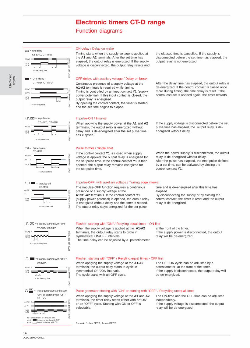
CT-ERD, CT-MFD
A1/A2
15/1815/16
ON-delay / Delay on make
Timing starts when the supply voltage is applied atthe A1 and A2 terminals. After the set time haselapsed, the output relay is energized. If the supplyvoltage is disconnected, the output relay resets and
the elapsed time is cancelled. If the supply isdisconnected before the set time has elapsed, theoutput relay is not energized.
OFF-delay, with auxiliary voltage / Delay on break
Continuous presence of a supply voltage at theA1-A2 terminals is required while timing.Timing is controlled by an input contact Y1 (supplypower potential). If this input contact is closed, theoutput relay is energized.By opening the control contact, the timer is started,and the set time begins to elapse.
= OFF-delay
CT-AHD, CT-MFD
A1/A2
A1/Y1
15/1815/16
t = set delay time
After the delay time has elapsed, the output relay isde-energized. If the control contact is closed oncemore during timing, the time delay is reset. If thecontrol contact is opened again, the timer restarts.
= Impulse-on
CT-VWD, CT-MFD
A1/A2
15/1815/16
t = set pulse time
Impulse-ON / Interval
When applying the supply power at the A1 and A2terminals, the output relay is energized withoutdelay and is de-energized after the set pulse timehas elapsed.
If the supply voltage is disconnected before the setpulse time has elapsed, the output relay is de-energized without delay.
Flasher, starting with "ON" / Recyling equal times - ON first = Flasher, starting with "ON"
CT-EBD, CT-MFD
t = set flashing time
When the supply voltage is applied at the A1-A2terminals, the output relay starts to cycle insymmetrical ON/OFF intervals.The time delay can be adjusted by a potentiometer
A1/A2
X1-Y1
15/1815/16
= Pulse generator starting with
"ON" or starting with "OFF"CT-TGD
Pulse generator starting with "ON" or starting with "OFF" / Recycling unequal times
= Pulse formerCT-MFD
t = set pulse time
A1/A2
Y1
15/18
Pulse former / Single shot
If the control contact Y1 is closed when supplyvoltage is applied, the output relay is energized forthe set pulse time. If the control contact Y1 is thenopened, the output relay remains energized forthe set pulse time.
When the power supply is disconnected, the outputrelay is de-energized without delay.After the pulse has elapsed, the next pulse definedby a set time, can be activated by closing thecontrol contact Y1.
Impulse-OFF, with auxiliary voltage / Trailing edge interval = Impulse-offCT-MFD
t = set pulse time
The impulse-OFF function requires a continuouspresence of a supply voltage at theA1/B1-A2 terminals. If the control contact Y1(supply power potential) is opened, the output relayis energized without delay and the timer is started.The output relay stays energized for the set pulse
t = set flashing time
=Flasher, starting with "OFF"
CT-MFD
Flasher, starting with "OFF" / Recyling equal times - OFF first
When applying the supply voltage at the A1 and A2terminals, the timer relay starts either with an"ON"or an "OFF" cycle. Starting with ON or OFF isselectable.
When applying the supply voltage at the A1-A2terminals, the output relay starts to cycle insymmetrical OFF/ON intervals.The cycle starts with an OFF cycle.
Electronic timers CT-D rangeFunction diagrams
Remark: 1c/o = SPDT; 2c/o = DPDT
time and is de-energized after this time haselapsed.By disconnecting the supply or by closing thecontrol contact, the timer is reset and the outputrelay is de-energized.
at the front of the timer.If the supply power is disconnected, the outputrelay will be de-energized.
The OFF/ON cycle can be adjusted by apotentiometer at the front of the timer.If the supply is disconnected, the output relay willbe de-energized.
The ON-time and the OFF-time can be adjustedindependenty.If the supply voltage is disconnected, the outputrelay will be de-energized.
tp = break time / ti = impulse timeA1/Y1 (closed) = starting with OFFA1/Y1 (open) = starting with ON

152CDC110004C0201
Ele
ctro
nic
timer
s1SV
C 1
10 0
00 F
044
21S
VC
110
000
F 0
443
1SV
C 1
10 0
00 F
044
41S
VC
110
000
F 0
446
1SV
C 1
10 0
00 F
044
51S
VC
110
000
F 0
447
t = set delay time
= ON-delayC5600, C5610, C5620
2-10
1/3,11/91/4,11/8
1/3,11/91/4,11/8
ON- delay / Delay on make
Timing starts when the supply voltage is applied atthe 2-10 terminals. After the set time has elapsed,the output relay is energized. If the supply voltageis disconnected, the output relay resets and theelapsed time is cancelled.
If the supply is disconnected before the set timehas elapsed, the output relay is not energized.
OFF-delay, with auxiliary voltage / Delay on break
Continuous presence of a supply voltage at the2-10 terminals is required while timing.Timing is controlled by an input contact 2-5 (supplypower potential). If this input contact is closed, theoutput relay is energized.By opening the control contact, the timer is started,and the set time begins to elapse.
= OFF- delayC5610, C5620
2-10
2-5
1/31/4
t = set delay time
After the delay time has elapsed,the output relay isde-energized. If the control contact is closed oncemore while the timer is energized, the time delay isreset. If the control contact is opened again, thetimer restarts.
= Impulse-ONC5610, C5620
2-10
1/31/4
t = set pulse time
Impulse-ON / Interval
When applying the supply voltage at the 2-10terminals, the output relay is energized withoutdelay and is de-energized after the set pulse timehas elapsed.
If the supply voltage is disconnected before the setpulse time has elapsed, the output relay is de-energized without delay.
Flasher, starting with "ON" / Recyling equal times-ON first = Flasher, starting with "ON"
C5620
t = set flashing time
When the supply power is applied at the 2-10terminals, the output relay starts to switch insymmetrical ON/ OFF intervals.
= Pulse formerC5610, C5620
t = set pulse time
Pulse former / Single shot
If the control contact 2-10 is closed when supplyvoltage is applied, the output relay is energized forthe set pulse time. If the control contact 2-5 isthen opened, the output relay remains energizedfor the set pulse time.
When the power supply is disconnected, the outputrelay is de-energized without delay.After the pulse has elapsed, the next pulse definedby the set time can be activated by closing thecontrol contact 2-5.
t = set flashing time
=Flasher, starting with "OFF"
C5620
Flasher, starting with "OFF" Recyling equal times-OFF first
When applying the supply power at the 2-10terminals, the output relay starts to flash insymmetrical OFF/ON intervals.The cycle starts with an OFF.
2-10
2-5
1/31/4
2-10
1/31/4
2-10
1/31/4
Electronic timers C56xx rangeFunction diagrams
Remark: 1c/o = SPDT; 2c/o = DPDT
The time delay can be adjusted by a potentiometerat the front of the timer.If the supply power is disconnected, the outputrelay will be de-energized.
The OFF/ON cycle can be adjusted by apotentiometer at the front of the timer.If the supply is disconnected, the output relay willbe de-energized.

162CDC110004C0201
Ele
ctro
nic
timer
s
Electronic timers CT-S rangeTechnical data
Terminals used CT-S range
Input circuits
Supply voltage - power consumption A1-A2 24-240VAC/DC - approx. 2-2.5VA/W 5)
A1-A2 12-40VAC - approx. 0.6-1.8VA
A1-A2 12-60VDC - approx. 0.6-2.5VA
B1-A2 24VAC/DC - approx. 0.5VA/W
B2-A2 42-48VAC/DC - approx. 1.8VA/W
A1-A2 110-240VAC - approx. 2-3VA1) / approx. 2.5-12VA
A1-A2 380-440VAC - approx. 3VA
Tolerance of the supply voltage -15%...+10%
Supply voltage frequency AC/DC versions DC (0Hz), 50/60Hz
AC versions 50/60Hz
Control contact connections, volt-free2) Y1-Z2 external timer start
X1-Z2 timer stop, time storage
Minimum control pulse length 20ms
Floating voltage at the control contacts3) 10-40VDC
Max. current in the control circuit 1mA
Max. cable length to the control inputs 50m
Remote potentiometer connection Z1-Z2 50kΩMax. cable length to remote potentiometer 2x25m, shield to Z2 potential
Duty time 100%
Timing circuititititit
Time ranges 10 time ranges 0.05s-300h
1.) 0.05-1s 2.) 0.15-3s 3.) 0.5-10s 4.) 1.5-30s 5.) 5-100s 6.) 15-300s 7.) 1.5-30min 8.) 15-300min
9.) 1.5-30h 10.) 15-300h
Recovery time <50ms
Repeat accuracy (constant parameters) <0.2%
Timing error within the tolerance of supply voltage <0.008% / % ∆ U
Timing error within temperature range <0.07% / °C
Display of operational states
Supply voltage / timer green LED steady / flashing while timing
1. Output relay energized red LED
2. Output relay energized red LED
Output circuits 15-16/18, 25(21)-26(22)/28(24)
No. of contacts Relays, 1 or 2c/o(2nd c/o with selectable instant. function)
Contact material AgCdo
Rated voltage acc. to VDE0110, IEC947-1 250V
Max. switching voltage 250VAC, 250VDC
Rated switching current acc. to IEC941-x AC12 (resistive) 230V 4A
Rated switching current acc. to IEC941-x AC15 (inductive) 230V 3A
Rated switching current acc. to IEC941-x DC12 (resistive) 24V 4A
Rated switching current acc. to IEC941-x DC13 (inductive) 24V 2A
Maximum mechanical life 30x106
Maximum electrical life (acc. to AC12, 230V, 4A) 0.1x10⁶
Short circuit proof, max. fuse rating n/c 10A fast, operating class gL
n/o 10A fast, operating class gL
Remark: 1c/o = SPDT; 2c/o = DPDT

172CDC110004C0201
Ele
ctro
nic
timer
s
1SV
C 1
10 0
00 F
018
8
1SV
C 1
10 0
00 F
018
9
1SV
C 1
10 0
00 F
018
5
1SV
C 1
10 0
00 F
018
4
Electronic timers CT-S rangeTechnical data, standards, load limit curves
AC load (resistive) DC load (resistive) Reduction factor for inductiveAC load
Reduction factor Ffor inductive load
Contact life/number of operations N220 V 50 Hz 1 AC360 operations/h
Load limit curves
CT-S range
General data
Width of the enclosure 22.5mm
Wire size 2x2.5mm2 (2x14AWG) stranded with wire end ferrule
Weight approx. 150g/5.3oz
Mounting position any
Degree of protection enclosure / terminals IP50/IP20
Operating temperature -20°C...+60°C
Storage temperature -40°C...+85°C
Mounting DIN rail (EN50022)
Mechanical shock resistance acc. to IEC68-2-6 6G
Standards / directives
Product standard parts of IEC 255 , IEC 1812-1
Electromagnetic compatibility 93/68/EWG
EMC-tests acc. to EN50082-2
ESD acc. to IEC1000-4-2, EN61000-4-2 level 3-6kV/8kV
HF radiation resistance acc. to IEC1000-4-3, EN61000-4-3 level 3-10V/m
Burst acc. to IEC1000-4-4, EN61000-4-4 level 3-2 kV/5 kHz
Surge acc. to IEC1000-4-5, EN61000-4-5 level 4-2kV L-L
HF line emission acc. to IEC1000-4-6, EN61000-4-6 level 3-10V
Low voltage directive 93/68/EWG
Resistance to vibration 10G, f = 55Hz, a = 0.95mm, t = 2h per level
Approvals cULus, GL, GOST
Isolation data
Rated Isolation voltage to VDE0110, IEC947-1 Supply 240V-300Vbetween supply-, control- and output circuit Supply 440V-500V
Rated impulse withstand voltage to VDE0110, 4kV/1.2-50µsIEC664 -between all isolated circuits
Test voltage between all isolated circuits 2.5kV, 50Hz, 1min. 4)
Pollution category acc. to VDE0110, IEC664/IEC255-5 III/C
Overvoltage category acc. to VDE0110, IEC664/IEC255-5 III/C
Environmental tests acc. to IEC68-2-30 24h cycle, 55°C, 93% rel., 96h
5) CT-ARS: 24VAC/DC - approx. 1A for 30ms18VAC/DC - approx. 1A for 20ms110-130VAC - approx. 1A for 15ms220-240VAC - approx. 1A for 10ms
1) CT-MBS 1c/o, CT-MBS 2c/o, CT-ERS 1c/o,CT-EVS, CT-APS, CT-EBS 1c/o
2) see connection example page 23, 243) no galvanic isolation to supply circuit4) 2kV, 50Hz, 1min. for CT-ARS
Contact life

182CDC110004C0201
Ele
ctro
nic
timer
s
Electronic timers CT-E rangeTechnical data
Terminals used CT-E range
Input circuits
Supply voltage - power consumption A1-A2 24-240VAC/DC - approx. 1.0-2.0VA/WA1-A2 110-130VAC - approx. 2.0VAA1-A2 220-240VAC - approx. 2.0VAB1-A2 24VAC/DC - approx. 1.0VA/W
Tolerance of the supply voltage -15%...+10%
Supply voltage frequency AC/DC version DC (0Hz), 50/60HzAC version 50/60Hz
Control contact connections, non-volt free1) Y1 external timer start-up
Control contact potential Supply voltage
Minimum controller pulse length 20ms
Duty time 100%
Minimum energizing time (CT-ARE) 200ms
Solid-state devices CT-MKE, CT-EKE, CT-AKE
Voltage drop in closed state ≤ 3V
Power consumption while timing ≤ 2mA (24-60VAC/DC)≤ 8mA (60-240VAC/DC)
Cable length CT-MKE, CT-EKE, CT-AKE
Between solid-state timer and connected load at 50Hz at 24VAC-220m/22nFand a cable capacity of 100pF/m: at 42VAC-100m/10nF
at 60VAC-65m/6.5nFat 110VAC-50m/5 nFat 240VAC-22m/2.2nF
Timing circuititititit
Time rangesSingle function timers 1 time range per unit
0.05-1s, 0.1-10s, 0.3-30s, 3-300s, 0.3-30minMultifunction timers CT-MFE 8 time ranges 0.05s-100h
CT-MKE 2 time ranges 0.1-10s and 3-300sStardelta changeover time CT-YDE-50ms, CT-SDE-30ms
Recovery time <50ms (<100ms CT-MKE, <300ms CT-AKE, <200ms CT-ARE,<400ms CT-AWE, CT-SDE, <500ms CT-YDE)
Repeat accuracy (constant parameters) <1%
Timing error within the tolerance of the supply voltage <0.5% / % ∆ U
Timing error within temperature range <0.1% (<0.06% / °C CT-MFE)B
Display of operational states
Supply voltage green LED
Output relay energized red LED
Output circuit, relay devices 15-16/18
No. of contacts Relay, 1c/o
Contact material AgCdo
Rated voltage acc. to VDE0110, IEC947-1 250V
Switching voltage max. 250VAC, 250VDC
Rated switching current acc. to IEC941-x AC12 (resistive) 230V 4A
Rated switching current acc. to IEC941-x AC15 (inductive) 230V 3A
Rated switching current acc. to IEC941-x DC12 (resistive) 24V 4A
Rated switching current acc. to IEC941-x DC13 (inductive) 24V 2A
Maximum mechanical life 30x106
Maximum electrical life (acc. to AC12, 230V, 4A) 0.1x10⁶
Short circuit proof, max. fuse rating n/c 10A fast, operating class gL (5A CT-ARE)
n/o 10A fast, operating class gL (5A CT-ARE)
Remark: 1c/o = SPDT

192CDC110004C0201
Ele
ctro
nic
timer
s
1SV
C 1
10 0
00 F
018
8
1SV
C 1
10 0
00 F
018
9
1SV
C 1
10 0
00 F
018
5
1SV
C 1
10 0
00 F
018
4
Electronic timers CT-E rangeTechnical data, standards, load limit curves
AC load (resistive) DC load (resistive)Contact life
Reduction factorfor inductive AC load
Reduction factor Ffor inductive load
Contact life/number of operations N220V 50Hz 1AC360 operations/h
Load limit curves
CT-E range
Output circuits solid-state devices CT-MKE, CT-EKE, CT-AKE A1-A2, A1-AL
Thyristor (CT-MKE, CT-EKE, CT-AKE)
Rated voltage acc. to VDE0110, IEC947-1 250V
Switching voltage max. 240V
Load current min. 20mA (10mA CT-EKE, CT-AKE)
Load current max. 0.8A at TA=20°C (0.7A CT-EKE, CT-AKE)
Load current reduced / derating 10mA/°C
Surge current max. ≤ 20A for t ≤ 20ms (≤ 15A CT-EKE, CT-AKE)
General data
Width of the enclosure 22.5mm
Wire size 2x1.5mm2(2x16AWG) stranded with wire end ferrule
Weight approx. 80g / approx. 2.8oz
Mounting position any
Degree of protection enclosure / terminals IP50/IP20
Operating temperature -20°C...+60°C
Storage temperature -40°C...+85°C
Mounting of DIN rail (EN50022)
Mechanical shock resistance acc. to IEC68-2-6 10G
Standards / directivesProduct standard parts of IEC255, IEC 1812-1
Electromagnetic compatibility 93/68/EWG
EMC-tests acc. to EN50082-2
ESD acc. to IEC1000-4-2, EN61000-4-2 level 3-6kV/8 kV
HF radiation resistance acc. to IEC1000-4-3, EN61000-4-3 level 3-10V/m
Burst acc. to IEC1000-4-4, EN61000-4-4 level 3-2kV/5kHz
Surge acc. to IEC1000-4-5, EN61000-4-5 level 4-2kV L-L
HF line emission acc. to IEC1000-4-6, EN61000-4-6 level 3-10V
Low voltage directive 93/68/EWG
Resistance to vibration 10G, f = 55Hz, a = 0.95mm, t = 2h per level
Approvals cULus, GL, GOST
Isolation data
Rated isolation voltage to VDE0110, IEC947-1 supply up to 240V-300Vbetween supply-, control- and output circuits supply up to 440V-500V
Rated impulse withstand voltage to VDE0110, 4kV/1.2-50µsIEC664 -between all isolated circuits
Test voltage between all isolated circuits 2.5kV, 50Hz, 1min.
Pollution category acc. to VDE0110, IEC664/IEC255-5 III/C
Overvoltage category acc. to VDE0110, IEC664/IEC255-5 III/C
Environmental tests acc. to IEC68-2-30 24h cycle, 55°C, 93% rel., 96h
1) see connection example page 25

202CDC110004C0201
Ele
ctro
nic
timer
s
Electronic timers CT-D rangeTechnical data
Terminals used CT-D range
Input circuits
Supply voltage - power consumption A1-A2 24-240VAC / 24-48VDC - approx. VA/W
Tolerance of the supply voltage -15%...+10%
Supply voltage frequency DC supply DC / 0HzAC supply 50/60Hz
Control contact connections, non-volt free1) Y1-A2 external timer start-up
Minimum control input pulse length 20ms
Max. cable length to the control inputs
Duty time 100%
Timing circuititititit
Time ranges 7 time ranges 0.05s-100h
1.) 0.05-1s 2.) 0.5-10s 3.) 5-100s 4.) 0.5-10min 5.) 5-100min6.) 0.5-10h 7.) 5-100h
Recovery time <50ms
Repeat accuracy (constant parameters) < +/- 0.5%
Timing error within the tolerance of the supply voltage <0.5%
Timing error within temperature range <0.06% / °C
Display of operating status
Supply voltage / timer green LED steady / flashing while timing
Output relay energized red LED
Output circuits 15-16/18
No. of contacts relay, 1c/o
Contact material AgSnO2
Rated voltage acc. to VDE0110, IEC947-1 250V
Switching voltage min. 12V
Switching voltage max. 250VAC
Switching current min. 100mA
Switching current max. 8A
Rated switching current acc. to IEC941-x AC12 (resistive) 230V 4A
Rated switching current acc. to IEC941-x AC15 (inductive) 230V 3A
Rated switching current acc. to IEC941-x DC12 (resistive) 24V 4A
Rated switching current acc. to IEC941-x DC13 (inductive) 24V 2A
Maximum mechanical life 30x106
Maximum electrical life (acc. to AC12, 230V, 4A) 0.1x10⁶
Short circuit proof, max. fuse rating n/c 6A fast, operating class gL
n/o 10A fast, operating class gL
General data
Width of the enclosure 17.5mm
Wire size 2x1.5mm2 (2x16AWG) stranded with wire end ferrule2x2.5mm2 (2x14AWG) without wire end ferrule
Weight approx. 60g / approx. 2.1oz
Mounting position any
Degree of protection enclosure / terminals IP50 / IP20
Operating temperature -20°C...+60°C
Storage temperature -40°C...+85°C
Mounting DIN rail (EN50022), snap-on mounting
Mechanical shock resistance acc. to IEC68-2-6 6G
Remark: 1c/o = SPDT
212CDC110004C0201
Ele
ctro
nic
timer
s
1SV
C 1
10 0
00 F
044
8
1SV
C 1
10 0
00 F
044
9
1SV
C 1
10 0
00 F
018
5
1SV
C 1
10 0
00 F
045
0
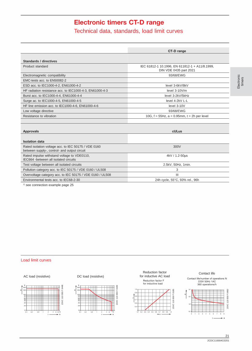
Electronic timers CT-D rangeTechnical data, standards, load limit curves
Load limit curves
CT-D range
Standards / directives
Product standard IEC 61812-1 10.1996, EN 611812-1 + A11/8.1999,DIN VDE 0435 part 2021
Electromagnetic compatibility 93/68/EWG
EMC-tests acc. to EN50082-2
ESD acc. to IEC1000-4-2, EN61000-4-2 level 3-6kV/8kV
HF radiation resistance acc. to IEC1000-4-3, EN61000-4-3 level 3-10V/m
Burst acc. to IEC1000-4-4, EN61000-4-4 level 3-2kV/5kHz
Surge ac. to IEC1000-4-5, EN61000-4-5 level 4-2kV L-L
HF line emission acc. to IEC1000-4-6, EN61000-4-6 level 3-10V
Low voltage directive 93/68/EWG
Resistance to vibration 10G, f = 55Hz, a = 0.95mm, t = 2h per level
Approvals cULus
Isolation data
Rated isolation voltage acc. to IEC 50175 / VDE 0160 300Vbetween supply-, control- and output circuit
Rated impulse withstand voltage to VDE0110, 4kV / 1.2-50µsIEC664 -between all isolated circuits
Test voltage between all isolated circuits 2.5kV, 50Hz, 1min.
Pollution category acc. to IEC 50175 / VDE 0160 / UL508 3
Overvoltage category acc. to IEC 50175 / VDE 0160 / UL508 III
Environmental tests acc. to IEC68-2-30 24h cycle, 55°C, 93% rel., 96h1) see connection example page 25
AC load (resistive) DC load (resistive)Contact lifeReduction factor
for inductive AC loadReduction factor Ffor inductive load
Contact life/number of operations N220V 50Hz 1AC360 operations/h
222CDC110004C0201
Ele
ctro
nic
timer
s
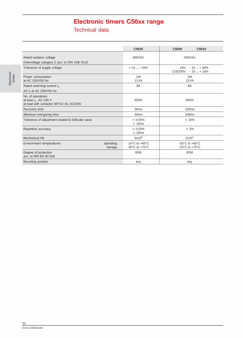
Electronic timers C56xx rangeTechnical data
C5620 C5600 C5610
Rated isolation voltage 250VAC 250VAC
Overvoltage category C acc. to DIN VDE 0110
Tolerance of supply voltage + 10 ... - 15% 24V: - 15 ... + 30%115/230V: - 15 ... + 10%
Power consumption 1W 1Wat AC 230V/50 Hz 11VA 11VA
Rated switching current Ie 8A 8A
AC-1 at AC 230V/50 Hz
No. of operationsat load Ie , AC 230 V 600/h 600/hat load with contactor 3RT10 16, AC230V
Recovery time 50ms 100ms
Minimum energizing time 50ms 100ms
Tolerance of adjustment related to fullscale value w 0.03% w 10%w 10ms
Repetitive accuracy w 0.03% w 2%w 10ms
Mechanical life 5x10⁶ 2x10⁷
Environment temperatures operating -10°C to +60°C -20°C to +60°Cstorage -30°C to +70°C -25°C to +70°C
Degree of protection IP65 IP50acc. to DIN EN 60 529
Mounting position any any

232CDC110004C0201
Ele
ctro
nic
timer
s
1SV
C 1
10 0
00 F
038
7
1SV
C 1
10 0
00 F
038
1
1SV
C 1
10 0
00 F
039
1
1SV
C 1
10 0
00 F
039
31S
VC
110
000
F 0
380
1SV
C 1
10 0
00 F
038
8
1SV
C 1
10 0
00 F
038
2
1SV
C 1
10 0
00 F
039
01S
VC
110
000
F 0
392
1SV
C 1
10 0
00 F
038
3
1SV
C 1
10 0
00 F
038
9
Electronic timers CT-S rangeWiring diagrams, connection examplesstar-delta applications
Connection diagram of the control contacts
CT-S range wiring diagrams
Connection diagram using a remote potentiometer
Connection diagram of a proximity switch (3 wire)with 230VAC supply
Connection diagram of a proximity switch (3 wire)with 24VDC supply
For multifunction timer CT-MFS
this jumper is not required
Diagram of control circuit
CT-YDEW
Star-delta timer with relay outputimpulse function
CT-YDAV
Star-delta timer with relay output Diagram of control circuit
CT-YDE
Star-delta timer with relay output Diagram of control circuit
Diagram of control circuit
CT-SDE
Star-delta timer with relay outputDiagram of main circuit
Version 380-440VAC
1SV
C 1
10 0
00 F
069
71S
VC
110
000
F 0
698
1SV
C 1
10 0
00 F
069
9

242CDC110004C0201
Ele
ctro
nic
timer
s
1SV
C 1
10 0
00 F
041
1
1SV
C 1
10 0
00 F
041
2
1SV
C 1
10 0
00 F
041
3
1SV
C 1
10 0
00 F
041
9
1SV
C 1
10 0
00 F
041
4
1SV
C 1
10 0
00 F
041
5
1SV
C 1
10 0
00 F
041
6
1SV
C 1
10 0
00 F
041
7
1SV
C 1
10 0
00 F
041
8
1SV
C 1
10 0
00 F
042
1
1SV
C 1
10 0
00 F
042
2
1SV
C 1
10 0
00 F
039
4
1SV
C 1
10 0
00 F
049
3
1SV
C 1
10 0
00 F
049
4
1SV
C 1
10 0
00 F
039
5
1SV
C 1
10 0
00 F
039
6
1SV
C 1
10 0
00 F
049
5
1SV
C 1
10 0
00 F
049
6
1SV
C 1
10 0
00 F
039
8
1SV
C 1
10 0
00 F
039
9
1SV
C 1
10 0
00 F
039
7
1SV
C 1
10 0
00 F
040
2
1SV
C 1
10 0
00 F
040
3
1SV
C 1
10 0
00 F
040
5
1SV
C 1
10 0
00 F
040
6
1SV
C 1
10 0
00 F
040
0
1SV
C 1
10 0
00 F
040
4
1SV
C 1
10 0
00 F
040
1
1SV
C 1
10 0
00 F
042
0
1SV
C 1
10 0
00 F
040
7
1SV
C 1
10 0
00 F
040
8
1SV
C 1
10 0
00 F
040
9
1SV
C 1
10 0
00 F
041
0
1SV
C 1
10 0
00 F
038
1
CT-EBS CT-EBS CT-TGS CT-PGS CT-YDAV
CT-IRS CT-IRS CT-IRS CT-IRS
Version with goldplated contacts
Dimensional drawing
CT-VWS CT-AWS
CT-AWS
Electronic timers CT-S rangeConnection diagrams and position of connection terminalsDimensional drawing
CT-MFS CT-MBS CT-MBS CT-ERS
CT-ERS CT-ERS CT-AHS CT-AHS CT-APS CT-ARS
CT-ARS CT-EAS CT-EAS CT-EVS CT-VWS
Supply voltageversions
12-40VAC/12-60VDCand 380-440VAC
Supply voltageversions
12-40VAC/12-60VDCand 380-440VAC
Supply voltageversions
12-40VAC/12-60V DCand 380-440VAC
Version380-440VAC
CT-S range
Supply voltageversions
12-40VAC/12-60VDCand 380-440VAC
CT-YDEW

252CDC110004C0201
Ele
ctro
nic
timer
s
1SV
C 1
10 0
00 F
042
3
1SV
C 1
10 0
00 F
043
6
1SV
C 1
10 0
00 F
042
7
1SV
C 1
10 0
00 F
042
8
1SV
C 1
10 0
00 F
043
0
1SV
C 1
10 0
00 F
043
1
1SV
C 1
10 0
00 F
043
3
1SV
C 1
10 0
00 F
043
2
1SV
C 1
10 0
00 F
042
9
1SV
C 1
10 0
00 F
043
5
1SV
C 1
10 0
00 F
042
4
1SV
C 1
10 0
00 F
042
5
1SV
C 1
10 0
00 F
042
6
1SV
C 1
10 0
00 F
043
4
1SV
C 1
10 0
00 F
043
9
1SV
C 1
10 0
00 F
043
8
1SV
C 1
10 0
00 F
043
7
1SV
C 1
10 0
00 F
044
0
1SV
C 1
10 0
00 F
044
1
5
58
43,4
70
17,5
45
1SV
C 1
10 0
00 F
045
1
1SV
C 1
10 0
00 F
045
2
1SV
C 1
10 0
00 F
045
3
1SV
C 1
10 0
00 F
045
4
1SV
C 1
10 0
00 F
045
5
1SV
C 1
10 0
00 F
045
6
CT-MFE CT-ERE CT-ARE CT-VWECT-AWE 1)
without auxiliaryvoltage
CT-EBE CT-MKE CT-EKE CT-AKE CT-IRE
CT-AHS 1)
Dimensional drawings
Connection examples CT-E rangeSingle function devices with control contact
CT-MFD CT-ERD CT-AHD CT-VWD CT-EBD CT-TGD
Electronic timers CT-E range
Electronic timers CT-D range
CT-E range CT-D range
Electronic timers CT-E/CT-D rangeConnection diagrams and position of connection terminalsDimensional drawings
CT-AWE 1)
with auxiliaryvoltage

262CDC110004C0201
Ele
ctro
nic
timer
s
C 5620 C 5620 C 5620 C 5620
C 5620 C 5620 C 5600 C 5600
C 5610C 5610 C 5610 C 5610
C5620 C5600/C5610
1SV
C 1
10 0
00 F
037
7
1SV
C 1
10 0
00 F
037
4
1SV
C 1
10 0
00 F
037
8
1SV
C 1
10 0
00 F
037
5
1SV
C 1
10 0
00 F
037
1
1SV
C 1
10 0
00 F
037
2
1SV
C 1
10 0
00 F
037
3
1SV
C 1
10 0
00 F
037
6
1SV
C 1
10 0
00 F
036
3
1SV
C 1
10 0
00 F
036
3
Electronic timers C56xx rangeConnection diagrams and position of connection terminalsDimensional drawings
Dimensional drawings
AccessoriesSocket for C56xx Socket with backward connection forr C56xx
ON-delay (A) OFF-delay withauxiliary voltage (C)
Impulse-on (H) Pulse former withauxiliary voltage (B)
Flasher, starting with "OFF" (D) Flasher, starting with "ON" (Di) ON-delay (0)
OFF-delay withauxiliary voltage (C)
Impulse-on (H) Pulse former withauxiliary voltage (B)
ON-delay andinstantaneous contact (1)
ON-delay (A)
Panel thickness 1to 3,5 mm Panel exert
Mounting frame
Position screw
Panel exert
to

272CDC110004C0201
Ele
ctro
nic
timer
s
1SV
C 1
10 0
00 F
033
61S
VC
110
000
F 0
337
1SV
C 1
10 0
00 F
033
81S
VC
110
000
F 0
182
1SV
C 1
10 0
00 F
018
11S
VC
110
000
F 0
179
Electronic timers CT-S rangeAccessories
Diameter Degree of Order code Pack. unit Price Weightmm protection piece 1 piece 1 piece kg/oz
30.5 IP65 1SVR 700 800 R 1000 1 0.040/1.422.5 IP65 1SVR 701 800 R 1000 1 0.040/1.410.5 IP40 1SVR 214 017 R 0900 1 0.040/1.4
Remote potentiometer
50kΩ ±20%-0.2Ω with direct reading scale (graduated dial supplied)
Adapter for panel mounting
Marker
Sealable cover
Enclosure width in mm Order code Pack. unit Price Weightpiece 1 piece 1 piece kg/oz
22.5 1SVR 430 029 R 0100 1 0.020/0.7
Order code Pack. unit Price Weightpiece 1 piece 1 piece kg/oz
1SVR 366 017 R 0100 1 0.020/0.7
Enclosure width in mm Order code Pack. unit Price Weightpiece 1 piece 1 piece kg/oz
22.5 1SVR 430 005 R 0100 1 0.020/0.7

282CDC110004C0201
Ele
ctro
nic
timer
s
Conversion table C56xx range (discontinued) to new CT-S and CT-E rangeOld order code Type Description Supply New order code Type Description SupplyC56xx voltage CT- voltage
1SAR 330 020 R 0000 C 565 multifunction timer, 2c/o, 24-240VAC/DC -> 1SVR 430 010 R 0200 CT-MFS multifunction timer 2c/o, 24-240VAC/DC15 ranges (0.05s-100h) 10 ranges (0.05s-300h)
1SAR 330 020 R 0001 C 565 multifunction timer, 2c/o, 24VAC/DC, -> 1SVR 430 012 R 0200 CT-MBS multifunction timer 2c/o, 24VAC/DC,15 ranges (0.05s-100h) 100-127VAC10 10 ranges (0.05s-300h) 110-240VAC
1SAR 330 020 R 0002 C 565 multifunction timer, 2c/o, 24VAC/DC,15 ranges (0.05s-100h) 200-240VAC
1SAR 330 020 R 0009 C 565 multifunction timer, 2c/o, 24VAC/DC, -> 1SVR 430 011 R 2200 CT-MBS multifunction timer 2c/o, 380-440VAC15 ranges (0.05s-100h) 400-440VAC 10 ranges (0.05s-300h)
1SAR 330 010 R 0010 C 564 multifunction timer, 1c/o, 12VDC -> 1SVR 430 010 R 1100 CT-MBS multifunction timer 1c/o, 12-40VAC/15 ranges (0.05s-100h) 10 ranges (0.05s-300h) 12-60VDC
1SAR 330 010 R 0001 C 564 multifunction timer, 1c/o, 24VAC/DC, -> 1SVR 430 013 R 0100 CT-MBS multifunction timer 1c/o, 24VAC/DC,15 ranges (0.05s-100h) 100-127VAC 10 ranges (0.05s-300h) 110-240VAC
1SAR 330 010 R 0002 C 564 multifunction timer, 1c/o, 24VAC/DC,15 ranges (0.05s-100h) 200-240VAC
1SAR 330 010 R 0000 C 564 multifunction timer, 1c/o, 24-240VAC/DC -> 1SVR 550 029 R 8100 CT-MFE multifunction timer, 1c/o 24-240VAC/DC15 ranges (0.05s-100h) 8 ranges (0.05s-100h)
1SAR 310 010 R 0001 C 561.00 ON-delay timer, 15 ranges 24VAC/DC, -> 1SVR 430 102 R 0100 CT-ERS ON-delay timer 1c/o, 24VAC/DC,(0.05s-100h), 1c/o 100-127VAC 10 ranges (0.05s-300h) 110-240VAC
1SAR 310 010 R 0002 C 561.00 ON-delay timer, 15 ranges 24VAC/DC,(0.05s-100h), 1c/o 200-240VAC
1SAR 310 020 R 0003 C 561.01 ON-delay timer, 15 ranges 42-48VAC/DC, -> 1SVR 430 100 R 1200 CT-ERS ON-delay timer 2c/o, 12-40VAC/(0.05s-100h), 2c/o 60VAC/DC 10 ranges (0.05s-300h) 12-60VDC
1SAR 310 020 R 0001 C 561.01 ON-delay timer, 15 ranges 24VAC/DC, -> 1SVR 430 103 R 0200 CT-ERS ON-delay timer 2c/o, 24VAC/DC,(0.05s-100h), 2c/o 100-127V AC 10 ranges (0.05s-300h) 42-48VAC/DC, 110-240VAC
1SAR 310 020 R 0002 C 561.01 ON-delay timer, 15 ranges 24VAC/DC,(0.05s-100h), 2c/o 200-240VAC
1SAR 310 020 R 0000 C 561.01 ON-delay timer, 15 ranges 24-240VAC/DC(0.05s-100h), 2c/o
1SAR 340 017 R 0006 C 562.20 true OFF-delay timer, 7 ranges 24VAC/DC -> 1SVR 430 120 R 0100 CT-ARS true OFF-delay timer 1c/o, 24-240VAC/DC(0.05s-100s), 7 ranges (0.05s-10min) without auxiliary voltage
1SAR 340 017 R 0007 C 562.20 true OFF-delay timer, 7 ranges 100-127VAC/DC(0.05s-100s), 1c/o
1SAR 340 017 R 0008 C 562.20 true OFF-delay timer, 7 ranges 200-240VAC/DC(0.05s-100s), 1c/o
1SAR 340 027 R 0006 C 562.22 true OFF-delay timer, 7 ranges 24VAC/DC -> 1SVR 430 120 R 0300 CT-ARS true OFF-delay timer 2c/o, 24-240VAC/DC(0.05s-100s), 2c/o 7 ranges (0.05s-10min) without auxiliary voltage
1SAR 340 027 R 0007 C 562.22 true OFF-delay timer, 7 ranges 100-127VAC/DC(0.05s-100s), 2c/o
1SAR 340 027 R 0008 C 562.22 true OFF-delay timer, 7 ranges 200-240VAC/DC(0.05s-100s), 2c/o
1SAR 350 010 R 0001 C 563 pulse generator, 7 ranges 24VAC/DC, -> 1SVR 430 163 R 0100 CT-TGS pulse generator 1c/o., 24VAC/DC,(0.05s-100h), 1c/o 100-127VAC 2x10 ranges (0.05s-300h) 42-48VAC/DC, 110-240VAC
1SAR 350 010 R 0002 C 563 pulse generator, 7 ranges 24VAC/DC,(0.05s-100h), 1c/o 200-240VAC
1SAR 310 011 R 0002 C 561.10 ON-delay timer, 24VAC/DC, -> 1SVR 550 107 R 1100 CT-ERE ON-delay timer 24VAC/DC,0.5-10s, 1c/o 200-240VAC 0.1-10s, 1c/o 220-240VAC
1SAR 310 011 R 0001 C 561.10 ON-delay timer, 0.5-10s, 1c/o 24VAC/DC, -> 1SVR 550 100 R 1100 CT-ERE ON-delay timer 110-130VAC100-127VAC 0.1-10s, 1c/o
1SAR 310 012 R 0002 C 561.10 ON-delay timer, 1.5-30s, 1c/o 24VAC/DC, -> 1SVR 550 107 R 4100 CT-ERE ON-delay timer, 0.3-30s 1c/o 24VAC/DC,200-240VAC 220-240VAC
1SAR 310 012 R 0001 C 561.10 ON-delay timer,1.5-30s, 1c/o 24VAC/DC, -> 1SVR 550 100 R 4100 CT-ERE ON-delay timer,0.3-30s 1c/o 110-130VAC100-127VAC
1SAR 310 013 R 0002 C 561.10 ON-delay timer, 5-100s, 1c/o 24VAC/DC, -> 1SVR 550 107 R 2100 CT-ERE ON-delay timer, 3-300s, 1c/o 24VAC/DC,200-240VAC 220-240VAC
1SAR 310 013 R 0001 C 561.10 ON-delay timer, 5-100s, 1c/o 24VAC/DC, -> 1SVR 550 100 R 2100 CT-ERE ON-delay timer, 3-300s, 1c/o 110-130VAC100-127VAC
1SAR 320 011 R 0002 C 562.10 OFF-delay timer, 0.5-10s, 1c/o 24VAC/DC, -> 1SVR 550 118 R 1100 CT-AHE OFF-delay timer, 0.1-10s, 1c/o 24VAC/DC200-240VAC 1SVR 550 111 R 1100 CT-AHE OFF-delay timer, 0.1-10s, 1c/o 220-240VAC
1SAR 320 011 R 0001 C 562.10 OFF-delay timer, 0.5-10s, 1c/o 24VAC/DC, -> 1SVR 550 110 R 1100 CT-AHE OFF-delay timer, 0.1-10s, 1c/o 110-130VAC100-127VAC
1SAR 320 012 R 0002 C 562.10 OFF-delay timer, 1.5-30s, 1c/o 24VAC/DC, -> 1SVR 550 118 R 4100 CT-AHE OFF-delay timer, 0.3-30s, 1c/o 24VAC/DC200-240VAC 1SVR 550 111 R 4100 CT-AHE OFF-delay timer, 0.3-30s, 1c/o 220-240VAC
1SAR 320 012 R 0001 C 562.10 OFF-delay timer, 1.5-30s, 1c/o 24VAC/DC, -> 1SVR 550 110 R 4100 CT-AHE OFF-delay timer, 0.3-30s, 1c/o 110-130VAC100-127VAC
1SAR 320 013 R 0002 C 562.10 OFF-delay timer, 5-100s, 1c/o 24VAC/DC, -> 1SVR 550 118 R 2100 CT-AHE OFF-delay timer, 3-300s, 1c/o 24VAC/DC200-240VAC 1SVR 550 111 R 2100 CT-AHE OFF-delay timer, 3-300s, 1c/o 220-240VAC
1SAR 320 013 R 0001 C 562.10 OFF-delay timer, 5-100s, 1c/o 24VAC/DC, -> 1SVR 550 110 R 2100 CT-AHE OFF-delay timer, 3-300s, 1c/o 110-130VAC100-127VAC
1SAR 360 014 R 0002 C 561.13 star-delta timer, 1-20s, 24VAC/DC, -> 1SVR 430 213 R 0200 CT-YDEW star-delta timer 2c/o, 24VAC/DC,2 delayed n/o, 50 ms 100-127VAC 10 ranges (0.05s-300h) 42-48VAC/DC, 110-240VAC
1SAR 360 014 R 0001 C 561.13 star-delta timer, 1-20s, 24VAC/DC,2 delayed n/o, 50 ms 200-240VAC CT-SDE see page 7
1SAR 360 015 R 0002 C 561.13 star-delta timer, 3-60s, 24VAC/DC,2 delayed n/o, 50 ms 100-127VAC
1SAR 360 015 R 0001 C 561.13 star-delta timer, 3-60s, 24VAC/DC,2 delayed n/o, 50 ms 200-240VAC
1SBN 020 010 R 1001 TE5S-24 star-delta timer, 0.8-60s, 24VAC/DC -> 1SVR 430 213 R 0200 CT-YDEW star-delta timer 2c/o, 24VAC/DC,2 delayed n/o, 50 ms 10 ranges (0.05s-300h) 42-48VAC/DC, 110-240VAC
1SBN 020 010 R 1002 TE5S-120 star-delta timer, 0.8-60s,2 delayed n/o, 50 ms 110-120VAC CT-SDE see page 7
1SBN 020 010 R 1003 TE5S-240 star-delta timer, 0.8-60s,2 delayed n/o, 50 ms 220-240VAC
1SBN 020 010 R 1004 TE5S-440 star-delta timer, 0.8-60s,2 delayed n/o, 50 ms 380-440VAC
1SAR 370 006 R 0005 C 561.02 ON-delay timer, 0.05-240s, 24-66VAC/DC -> 1SVR 550 509 R 1000 CT-EKE ON-delay timer 0.1-10s,solid-state output solid-state output 24-240VAC/DC
1SAR 370 006 R 0004 C 561.02 ON-delay timer, 0.05-240s, 90-240VAC/DC 1SVR 550 509 R 4000 CT-EKE ON-delay timer 0.3-30s,solid-state output solid-state output 24-240VAC/DC
1SVR 550 509 R 2000 CT-EKE ON-delay timer 3-300s, 24-240VAC/DCsolid-state output
Electronic timersConversion table C56xx R CT-S/CT-E ranges
Remark: 1c/o = SPDT; 2c/o = DPDT