Embed Size (px)
Citation preview
Total Solution to Earthing & Lightning Protection | 9AKK106354A3360 12/1
12
Data & signal protection
Product selector - Data / Signal line protection 12/2
ESP D & TN Series 12/4
ESP E Series 12/6
ESP H Series 12/8
ESP D/BX Series 12/10
ESP SL Series 12/12
ESP SLX Series 12/14
ESP SL LED 4-20 mA Series 12/16
ESP SL 3-Wire Series 12/18
ESP Q & TNQ Series 12/20
ESP KS & KE Series 12/22
ESP PCB/D & PCB/TN Series 12/24
ESP PCB/E Series 12/26
ESP RTD, RTDQ & SL RTD Series 12/28
ESP RS485, RS485Q & SL RS485 Series 12/30
Electronic systems protectionData & signal protection
12/2 Total Solution to Earthing & Lightning Protection | 9AKK106354A3360
12
Total Solution to Earthing & Lightning Protection | 9AKK106354A3360 12/3
12
Data & signal protectionProduct selector - Data / Signal line protection
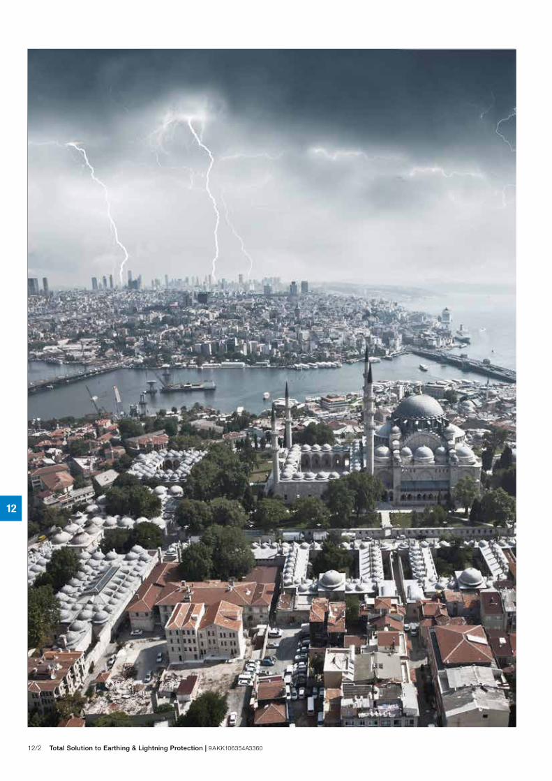
Selection guide - data/signal systems Installation locations Critical terminal equipment -
Common applications Service entrance located >20 m from service entrance
Protectors for specific systemsSystem Protector System Protector
RS 232 Data interfaces - Twisted pair data protection
Compact for limited space
Multiple line protection
RS 422 & RS 423 Data interfaces
ESP 15D Series ESP 15D/BX Series See pages 12/4 and 12/10
ESP 06E Series ESP SL06 Series See pages 12/6 and 12/12
ESP KS SeriesKE Series See pages 12/22 ESP Cat-5 SeriesESP Cat-6 Series See pages 13/8
ESP SL SeriesESP SL LED 4-20mA Series
See pages 12/12 and 12/16
ESP H Series
See pages 12/8
ESP RTD SeriesESP SL RTD SeriesESP RTDQ Series See pages 12/28
ESP D & Q SeriesESP KS Series See pages 12/4, 12/20 and 12/22
ESP SL LED Series
See pages 12/12
ESP PCB Series
See pages 12/24
ESP SL X Series
See pages 12/14ESP SL/3W Series
See pages 12/18
ESP RF Series See pages 14/16 & 14/18
ESP RS485 Series ESP SL RS485 Series ESP RS485Q Series See pages 12/30
ESP SL15 Series
See page 12/12 ESP LA Series
See page 13/10
ESP LB Series
See page 13/10
ESP LB Series
See page 13/10
ESP LN Series
See page 13/12
ESP 15Q Series See page 12/20
RS 485 Data interfaces
PBX systems terminating on LSA-Plus disconnection modules
Computer networks, including Power over Ethernet (PoE) (see Furse Application Note AN004)
4-20 mA loops and low current telemetry systems - Compact, for limited space
DC systems up to 110V, 4A
RTD systems (see Furse Application Note AN001)
Multiple line and PBX protection
DC systems up to 110V, 0.75 A - Compact, for limited space
Data interfaces at PCB level (see Furse Application Note AN003)
Hazardous area (process control, fire & gas detectors, 4-20 mA loops, shut down systems)
3-wire systems - Compact for limited space
RF radio and antenna communication systems

12/4 Total Solution to Earthing & Lightning Protection | 9AKK106354A3360
12
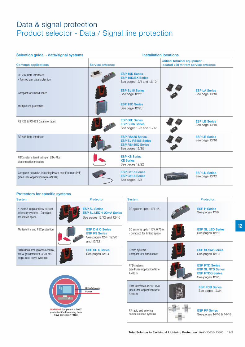
Combined Category D, C, B tested protector (to BS EN 61643) suitable for most twisted pair signalling applications. Available for working voltages of up to 6, 15, 30, 50 and 110 Volts. ESP TN suitable for Broadband, POTS, dial-up, T1/E1, lease line and *DSL telephone applications. For use at boundaries up to LPZ 0 to protect against flashover (typically the service entrance location) through to LPZ 3 to protect sensitive electronic equipment.
Data & signal protectionESP D & TN Series
InstallationConnect in series with the data communication or signal line either near where it enters or leaves the building or close to the equipment being protected (e.g. within its control panel). Either way, it must be very close to the system’s earth star point. Install protectors either within an existing cabinet/cubicle or in a separate enclosure.
Accessories
Combined Mounting/Earthing kits:CME 4 Mount & earth up to 4 protectorsCME 8 Mount & earth up to 8 protectorsCME 16 Mount & earth up to 16 protectorsCME 32 Mount & earth up to 32 protectors
Weatherproof enclosures:WBX 2/G For use with up to 2 protectorsWBX 3, WBX 3/G For use with up to 3 protectors
WBX 4, WBX 4/GS For use with a CME 4 and up to 4 protectorsWBX 8, WBX 8/GS For use with a CME 8 and up to 8 protectorsWBX 16/2/G For use with one or two CME 16 and up to 32 protectors
Full product range order codes can be found on pages 17/8-17/9
Install in series (in-line)
DIRTY CLEAN
From line To equipment Earth
Features & benefits – Very low let-through voltage (enhanced protection to
IEC/BS EN 62305) between all lines - Full Mode protection – Full Mode design capable of handling partial lightning
currents as well as allowing continual operation of protected equipment
– Repeated protection in lightning intense environments – Low in-line resistance minimizes unnecessary reductions
in signal strength – Strong, flame retardant, ABS housing – Supplied ready for flat mounting on base or side – Built-in DIN rail foot for simple clip-on mounting to top
hat DIN rails
– Colour coded terminals give a quick and easy installation check - grey for the dirty (line) end and green for the clean end
– Screen terminal enables easy connection of cable screen to earth
– Substantial earth stud to enable effective earthing – Integral earthing plate for enhanced connection to earth
via a CME kit – ESP 06D and ESP 50D have PADS reference 086/000551
(ESP 06D) and 086/000553 (ESP 50D) – ESP TN is suitable for telecommunication applications
in accordance with Telcordia and ANSI Standards (see Application Note AN005)
ApplicationUse on twisted pair lines, e.g. those found in process control equipment, modems and computer communications interfaces.
NOTE: Derivatives of these protectors are available ready-boxed to IP66, for use in damp or dirty environments. Slim Line (ESP SL), ATEX (ESP SLX) and PCB mount (ESP PCB) versions are also available. If your system requires a protector with a very low resistance or higher current, see the ESP E & H Series. Also use the ESP E Series for systems needing a higher bandwidth. Protectors for 3-wire (ESP SL/3W) and RTD (ESP RTD, ESP SL RTD) are available, as are the space saving protectors (ESP Q, ESP SL Series). The ESP KT and TN Series are additional protectors specifically for telephone lines. The ESP KS Series are protectors for data and signal lines on an LSA-PLUS module.
Total Solution to Earthing & Lightning Protection | 9AKK106354A3360 12/5
12
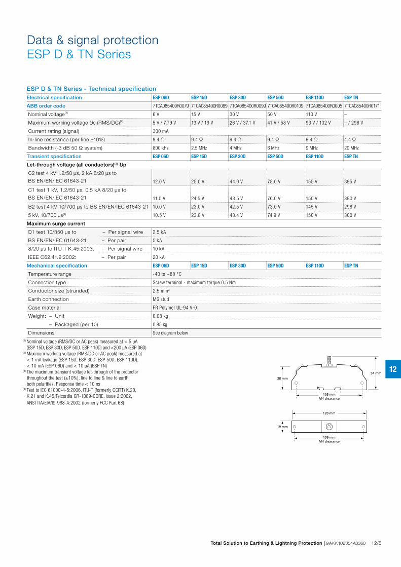
ESP D & TN Series - Technical specificationElectrical specification ESP 06D ESP 15D ESP 30D ESP 50D ESP 110D ESP TN
ABB order code 7TCA085400R0079 7TCA085400R0089 7TCA085400R0099 7TCA085400R0109 7TCA085400R0005 7TCA085400R0171
Nominal voltage(1) 6 V 15 V 30 V 50 V 110 V –
Maximum working voltage Uc (RMS/DC)(2) 5 V / 7.79 V 13 V / 19 V 26 V / 37.1 V 41 V / 58 V 93 V / 132 V – / 296 V
Current rating (signal) 300 mA
In-line resistance (per line ±10%) 9.4 Ω 9.4 Ω 9.4 Ω 9.4 Ω 9.4 Ω 4.4 Ω
Bandwidth (-3 dB 50 Ω system) 800 kHz 2.5 MHz 4 MHz 6 MHz 9 MHz 20 MHz
Transient specification ESP 06D ESP 15D ESP 30D ESP 50D ESP 110D ESP TN
Let-through voltage (all conductors)(3) Up
C2 test 4 kV 1.2/50 μs, 2 kA 8/20 μs to
BS EN/EN/IEC 61643-21 12.0 V 25.0 V 44.0 V 78.0 V 155 V 395 V
C1 test 1 kV, 1.2/50 μs, 0.5 kA 8/20 μs to
BS EN/EN/IEC 61643-21 11.5 V 24.5 V 43.5 V 76.0 V 150 V 390 V
B2 test 4 kV 10/700 μs to BS EN/EN/IEC 61643-21 10.0 V 23.0 V 42.5 V 73.0 V 145 V 298 V
5 kV, 10/700 μs(4) 10.5 V 23.8 V 43.4 V 74.9 V 150 V 300 V
Maximum surge current
D1 test 10/350 μs to – Per signal wire 2.5 kA
BS EN/EN/IEC 61643-21: – Per pair 5 kA
8/20 μs to ITU-T K.45:2003, – Per signal wire 10 kA
IEEE C62.41.2:2002: – Per pair 20 kA
Mechanical specification ESP 06D ESP 15D ESP 30D ESP 50D ESP 110D ESP TN
Temperature range -40 to +80 °C
Connection type Screw terminal - maximum torque 0.5 Nm
Conductor size (stranded) 2.5 mm2
Earth connection M6 stud
Case material FR Polymer UL-94 V-0
Weight: – Unit 0.08 kg
– Packaged (per 10) 0.85 kg
Dimensions See diagram below(1) Nominal voltage (RMS/DC or AC peak) measured at < 5 μA (ESP 15D, ESP 30D, ESP 50D, ESP 110D) and <200 μA (ESP 06D)(2) Maximum working voltage (RMS/DC or AC peak) measured at < 1 mA leakage (ESP 15D, ESP 30D, ESP 50D, ESP 110D), < 10 mA (ESP 06D) and < 10 μA (ESP TN)(3) The maximum transient voltage let-through of the protector throughout the test (±10%), line to line & line to earth, both polarities. Response time < 10 ns(4) Test to IEC 61000-4-5:2006, ITU-T (formerly CCITT) K.20, K.21 and K.45,Telcordia GR-1089-CORE, Issue 2:2002, ANSI TIA/EIA/IS-968-A:2002 (formerly FCC Part 68)
120 mm
38 mm
19 mm
54 mm
105 mmM4 clearance
109 mmM4 clearance
Data & signal protectionESP D & TN Series
12/6 Total Solution to Earthing & Lightning Protection | 9AKK106354A3360
12
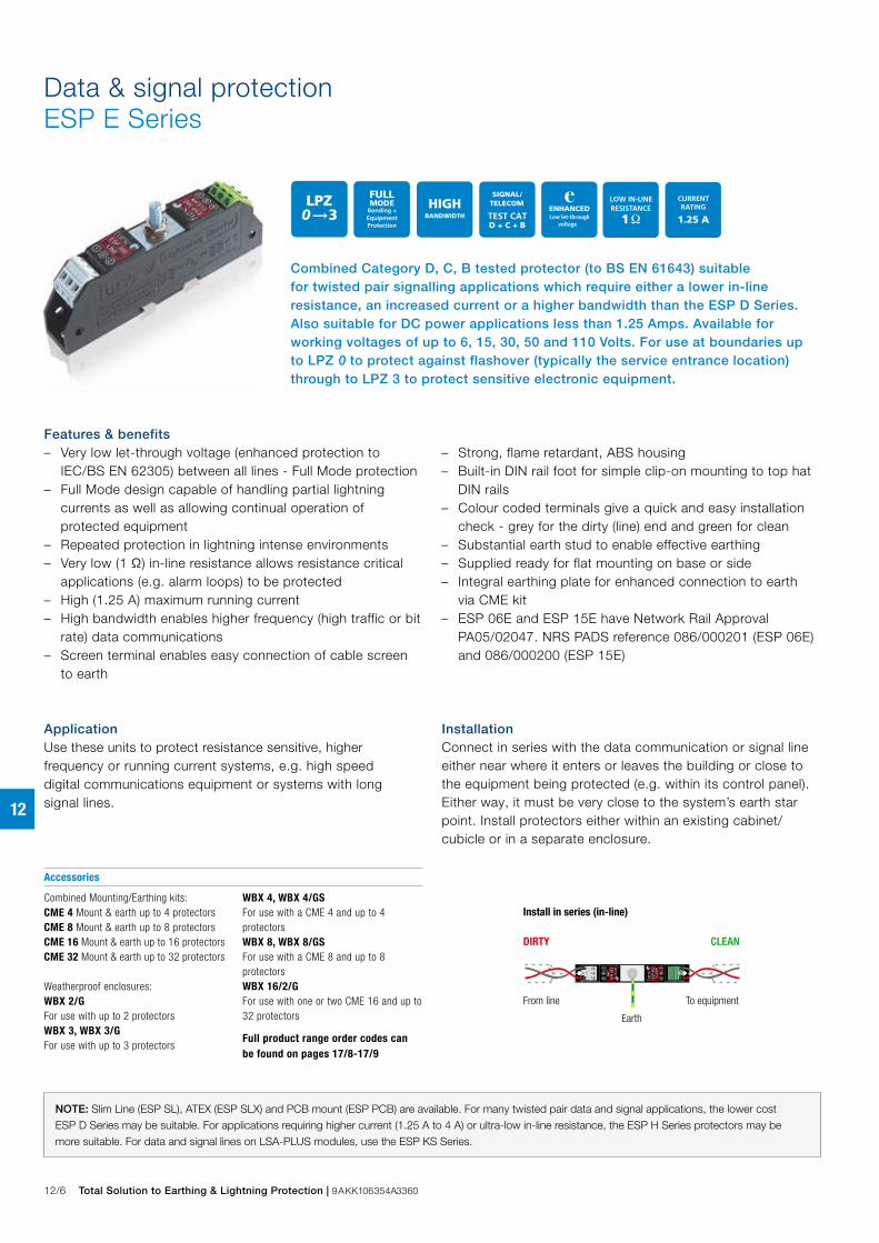
Combined Category D, C, B tested protector (to BS EN 61643) suitable for twisted pair signalling applications which require either a lower in-line resistance, an increased current or a higher bandwidth than the ESP D Series. Also suitable for DC power applications less than 1.25 Amps. Available for working voltages of up to 6, 15, 30, 50 and 110 Volts. For use at boundaries up to LPZ 0 to protect against flashover (typically the service entrance location) through to LPZ 3 to protect sensitive electronic equipment.
Data & signal protectionESP E Series
InstallationConnect in series with the data communication or signal line either near where it enters or leaves the building or close to the equipment being protected (e.g. within its control panel). Either way, it must be very close to the system’s earth star point. Install protectors either within an existing cabinet/cubicle or in a separate enclosure.
Accessories
Combined Mounting/Earthing kits:CME 4 Mount & earth up to 4 protectorsCME 8 Mount & earth up to 8 protectorsCME 16 Mount & earth up to 16 protectorsCME 32 Mount & earth up to 32 protectors
Weatherproof enclosures:WBX 2/G For use with up to 2 protectorsWBX 3, WBX 3/G For use with up to 3 protectors
WBX 4, WBX 4/GS For use with a CME 4 and up to 4 protectorsWBX 8, WBX 8/GS For use with a CME 8 and up to 8 protectorsWBX 16/2/G For use with one or two CME 16 and up to 32 protectors
Full product range order codes can be found on pages 17/8-17/9
Install in series (in-line)
DIRTY CLEAN
From line To equipment Earth
Features & benefits – Very low let-through voltage (enhanced protection to
IEC/BS EN 62305) between all lines - Full Mode protection – Full Mode design capable of handling partial lightning
currents as well as allowing continual operation of protected equipment
– Repeated protection in lightning intense environments – Very low (1 Ω) in-line resistance allows resistance critical
applications (e.g. alarm loops) to be protected – High (1.25 A) maximum running current – High bandwidth enables higher frequency (high traffic or bit
rate) data communications – Screen terminal enables easy connection of cable screen
to earth
– Strong, flame retardant, ABS housing – Built-in DIN rail foot for simple clip-on mounting to top hat
DIN rails – Colour coded terminals give a quick and easy installation
check - grey for the dirty (line) end and green for clean – Substantial earth stud to enable effective earthing – Supplied ready for flat mounting on base or side – Integral earthing plate for enhanced connection to earth
via CME kit – ESP 06E and ESP 15E have Network Rail Approval
PA05/02047. NRS PADS reference 086/000201 (ESP 06E) and 086/000200 (ESP 15E)
ApplicationUse these units to protect resistance sensitive, higher frequency or running current systems, e.g. high speed digital communications equipment or systems with long signal lines.
NOTE: Slim Line (ESP SL), ATEX (ESP SLX) and PCB mount (ESP PCB) are available. For many twisted pair data and signal applications, the lower cost ESP D Series may be suitable. For applications requiring higher current (1.25 A to 4 A) or ultra-low in-line resistance, the ESP H Series protectors may be more suitable. For data and signal lines on LSA-PLUS modules, use the ESP KS Series.

Total Solution to Earthing & Lightning Protection | 9AKK106354A3360 12/7
12
ESP E Series - Technical specificationElectrical specification ESP 06E ESP 15E ESP 30E ESP 50E ESP 110E
ABB order code 7TCA085400R0084 7TCA085400R0095 7TCA085400R0104 7TCA085400R0116 7TCA085400R0007
Nominal voltage(1) 6 V 15 V 30 V 50 V 110 V
Maximum working voltage Uc (RMS/DC)(2) 5 V / 7.79 V 11 V / 16.7 V 25 V / 36.7 V 40 V / 56.7 V 93 V / 132 V
Current rating (signal) 1.25 A
In-line resistance (per line ±10%) 1.0 Ω
Bandwidth (-3 dB 50 Ω system) 45 MHz
Transient specification ESP 06E ESP 15E ESP 30E ESP 50E ESP 110E
Let-through voltage (all conductors)(3) Up
C2 test 4 kV 1.2/50 μs, 2 kA 8/20 μs to
BS EN/EN/IEC 61643-21 36.0 V 39.0 V 60.0 V 86.0 V 180 V
C1 test 1 kV, 1.2/50 μs, 0.5 kA 8/20 μs to
BS EN/EN/IEC 61643-21 26.2 V 28.0 V 49.0 V 73.5 V 170 V
B2 test 4 kV 10/700 μs to BS EN/EN/IEC 61643-21 16.0 V 25.5 V 43.5 V 65.0 V 160 V
5 kV, 10/700 μs(4) 17.0 V 26.2 V 44.3 V 65.8 V 165 V
Maximum surge current
D1 test 10/350 μs to – Per signal wire 2.5 kA
BS EN/EN/IEC 61643-21: – Per pair 5 kA
8/20 μs to ITU-T K.45:2003, – Per signal wire 10 kA
IEEE C62.41.2:2002: – Per pair 20 kA
Mechanical specification ESP 06E ESP 15E ESP 30E ESP 50E ESP 110E
Temperature range -40 to +80 °C
Connection type Screw terminal - maximum torque 0.5 Nm
Conductor size (stranded) 2.5 mm2
Earth connection M6 stud
Case material FR Polymer UL-94 V-0
Weight: – Unit 0.08 kg
– Packaged (per 10) 0.85 kg
Dimensions See diagram below
(1) Nominal voltage (RMS/DC or AC peak) measured at < 10 μA (ESP 15E, ESP 30E, ESP 50E, ESP 110E) and < 200 μA (ESP 06E)(2) Maximum working voltage (RMS/DC or AC peak) measured at < 5 mA leakage (ESP 15E, ESP 30E, ESP 50E, ESP 110E) and < 10 mA (ESP 06E)(3) The maximum transient voltage let-through of the protector throughout the test (±10%), line to line & line to earth, both polarities. Response time < 10 ns(4) Test to IEC 61000-4-5:2006, ITU-T (formerly CCITT) K.20, K.21 and K.45,Telcordia GR-1089-CORE, Issue 2:2002, ANSI TIA/EIA/IS-968-A:2002 (formerly FCC Part 68)
120 mm
38 mm
19 mm
54 mm
105 mmM4 clearance
109 mmM4 clearance
Data & signal protectionESP E Series

12/8 Total Solution to Earthing & Lightning Protection | 9AKK106354A3360
12
Combined Category D, C, B tested protector (to BS EN 61643) suitable for twisted pair signalling applications which require either a lower in-line resistance or an increased current than the ESP D or E Series. Also suitable for DC power applications less than 4 Amps. Available for working voltages of up to 6, 15, 30, 50 and 110 Volts. For use at boundaries up to LPZ 0 to protect against flashover (typically the service entrance location) through to LPZ 3 to protect sensitive electronic equipment.
Data & signal protectionESP H Series
InstallationConnect in series with the data communication or signal line either near where it enters or leaves the building or close to the equipment being protected (e.g. within its control panel). Either way, it must be very close to the system’s earth star point. Install protectors either within an existing cabinet/cubicle or in a separate enclosure.
Accessories
Combined Mounting/Earthing kits:CME 4 Mount & earth up to 4 protectorsCME 8 Mount & earth up to 8 protectorsCME 16 Mount & earth up to 16 protectorsCME 32 Mount & earth up to 32 protectors
Weatherproof enclosures:WBX 2/G For use with up to 2 protectorsWBX 3, WBX 3/G For use with up to 3 protectors
WBX 4, WBX 4/GS For use with a CME 4 and up to 4 protectorsWBX 8, WBX 8/GS For use with a CME 8 and up to 8 protectorsWBX 16/2/G For use with one or two CME 16 and up to 32 protectors
Full product range order codes can be found on pages 17/8-17/9
Install in series (in-line)
DIRTY CLEAN
From line To equipment Earth
Features & benefits – Very low let-through voltage (enhanced protection to
IEC/BS EN 62305) between all lines - Full Mode protection – Full Mode design capable of handling partial lightning
currents as well as allowing continual operation of protected equipment
– Repeated protection in lightning intense environments – Ultra-low (< 0.05 Ω) in-line resistance allows resistance
critical applications (e.g. alarm loops) to be protected – Very high (4 A) maximum running current – Strong, flame retardant ABS housing
– Supplied ready for flat mounting on base or side – Built-in DIN rail foot for simple clip-on mounting to top
hat DIN rails – Colour coded terminals give a quick and easy installation
check - grey for the dirty (line) end and green for clean – Screen terminal enables easy connection of cable screen
to earth – Substantial earth stud to enable effective earthing – Integral earth plate enables enhanced connection to
earth via CME kit
ApplicationUse these applications to protect resistance sensitive or higher running current systems, e.g. systems with long signal lines, or DC power applications.
NOTE: For some data and signal applications with lower current, higher in-line resistance or higher bandwidth requirements, the ESP D or E Series protectors or the Slim Line ESP SL Series may be more suitable. If the protector is to be mounted directly onto a PCB, use the ESP PCB/**D or ESP PCB/**E protectors.

Total Solution to Earthing & Lightning Protection | 9AKK106354A3360 12/9
12
ESP H Series - Technical specificationElectrical specification ESP 06H ESP 15H ESP 30H ESP 50H ESP 110H
ABB order code 7TCA085400R0003 7TCA085400R0009 7TCA085400R0011 7TCA085400R0012 7TCA085400R0008
Nominal voltage(1) 6 V 15 V 30 V 50 V 110 V
Maximum working voltage Uc (RMS/DC)(2) 5 V / 7.79 V 11 V / 16.7 V 25 V / 36.7 V 40 V / 56.7 V 93 V / 132 V
Current rating (signal) 4 A
In-line resistance (per line ±10%) 0.05 Ω
Bandwidth (-3 dB 50 Ω system) 160 KHz 140 KHz 130 KHz 120 KHz 120 KHz
Transient specification ESP 06H ESP 15H ESP 30H ESP 50H ESP 110H
Let-through voltage (all conductors)(3) Up
C2 test 4 kV 1.2/50 μs, 2 kA 8/20 μs to
BS EN/EN/IEC 61643-21 12.0 V 27.5 V 46.0 V 67.0 V 150 V
C1 test 1 kV, 1.2/50 μs, 0.5 kA 8/20 μs to
BS EN/EN/IEC 61643-21 11.0 V 26.5 V 45.0 V 66.5 V 145 V
B2 test 4 kV 10/700 μs to BS EN/EN/IEC 61643-21 10.5 V 25.5 V 43.5 V 65.0 V 140 V
5 kV, 10/700 μs(4) 10.8 V 26.2 V 44.3 V 65.8 V 145 V
Maximum surge current
D1 test 10/350 μs to – Per signal wire 2.5 kA
BS EN/EN/IEC 61643-21: – Per pair 5 kA
8/20 μs to ITU-T K.45:2003, – Per signal wire 10 kA
IEEE C62.41.2:2002: – Per pair 20 kA
Mechanical specification ESP 06E ESP 15E ESP 30E ESP 50E ESP 110E
Temperature range -40 to +80 °C
Connection type Screw terminal - maximum torque 0.5 Nm
Conductor size (stranded) 2.5 mm2
Earth connection M6 stud - maximum torque 0.5 Nm
Case material FR Polymer UL-94 V-0
Weight: – Unit 0.08 kg
– Packaged (per 10) 0.85 kg
Dimensions See diagram below(1) Nominal voltage (RMS/DC or AC peak) measured at < 10 μA (ESP 15H, ESP 30H, ESP 50H, ESP 110H) and < 200 μA (ESP 06H)(2) Maximum working voltage (RMS/DC or AC peak) measured at < 5 mA leakage (ESP 15H, ESP 30H, ESP 50H, ESP 110H) and < 10 mA (ESP 06H)(3) The maximum transient voltage let-through of the protector throughout the test (±10%), line to line & line to earth, both polarities. Response time < 10 ns(4) Test to IEC 61000-4-5:2006, ITU-T (formerly CCITT) K.20, K.21 and K.45,Telcordia GR-1089-CORE, Issue 2:2002, ANSI TIA/EIA/IS-968-A:2002 (formerly FCC Part 68)
120 mm
38 mm
19 mm
54 mm
105 mmM4 clearance
109 mmM4 clearance
Data & signal protectionESP H Series
12/10 Total Solution to Earthing & Lightning Protection | 9AKK106354A3360
12
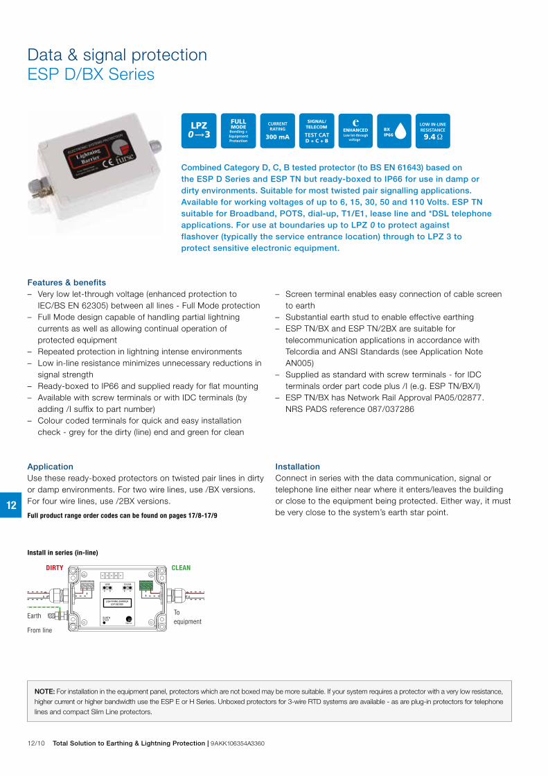
Combined Category D, C, B tested protector (to BS EN 61643) based on the ESP D Series and ESP TN but ready-boxed to IP66 for use in damp or dirty environments. Suitable for most twisted pair signalling applications. Available for working voltages of up to 6, 15, 30, 50 and 110 Volts. ESP TN suitable for Broadband, POTS, dial-up, T1/E1, lease line and *DSL telephone applications. For use at boundaries up to LPZ 0 to protect against flashover (typically the service entrance location) through to LPZ 3 to protect sensitive electronic equipment.
Data & signal protectionESP D/BX Series
A
LINE CLEAN
LIGHTNING BARRIERESP 06D/BX
EARTHSTUD
AB B
DIRTY CLEAN
Toequipment
From line
Earth
Install in series (in-line)
Features & benefits – Very low let-through voltage (enhanced protection to
IEC/BS EN 62305) between all lines - Full Mode protection – Full Mode design capable of handling partial lightning
currents as well as allowing continual operation of protected equipment
– Repeated protection in lightning intense environments – Low in-line resistance minimizes unnecessary reductions in
signal strength – Ready-boxed to IP66 and supplied ready for flat mounting – Available with screw terminals or with IDC terminals (by
adding /I suffix to part number) – Colour coded terminals for quick and easy installation
check - grey for the dirty (line) end and green for clean
– Screen terminal enables easy connection of cable screen to earth
– Substantial earth stud to enable effective earthing – ESP TN/BX and ESP TN/2BX are suitable for
telecommunication applications in accordance with Telcordia and ANSI Standards (see Application Note AN005)
– Supplied as standard with screw terminals - for IDC terminals order part code plus /I (e.g. ESP TN/BX/I)
– ESP TN/BX has Network Rail Approval PA05/02877. NRS PADS reference 087/037286
InstallationConnect in series with the data communication, signal or telephone line either near where it enters/leaves the building or close to the equipment being protected. Either way, it must be very close to the system’s earth star point.
ApplicationUse these ready-boxed protectors on twisted pair lines in dirty or damp environments. For two wire lines, use /BX versions. For four wire lines, use /2BX versions.
Full product range order codes can be found on pages 17/8-17/9
NOTE: For installation in the equipment panel, protectors which are not boxed may be more suitable. If your system requires a protector with a very low resistance, higher current or higher bandwidth use the ESP E or H Series. Unboxed protectors for 3-wire RTD systems are available - as are plug-in protectors for telephone lines and compact Slim Line protectors.

Total Solution to Earthing & Lightning Protection | 9AKK106354A3360 12/11
12
ESP D/BX Series - Technical specification
ESP 06D/BX ESP 15D/BX ESP 30D/BX ESP 50D/BX ESP 110D/BX ESP TN/BX
Electrical specification ESP 06D/2BX ESP 15D/2BX ESP 30D/2BX ESP 50D/2BX ESP 110D/2BX ESP TN/2BX
ABB order code 7TCA085400R0081 7TCA085400R0091 7TCA085400R0101 7TCA085400R0113 7TCA085400R0006 7TCA085400R0175
7TCA085400R0080 7TCA085400R0090 7TCA085400R0100 7TCA085400R0111 7TCA085460R0343 7TCA085400R0172
Nominal voltage(1) 6 V 15 V 30 V 50 V 110 V –
Maximum working voltage Uc (RMS/DC)(2) 5 V / 7.79 V 13 V / 19 V 26 V / 37.1 V 41 V / 58 V 93 V / 132 V – / 296 V
Current rating (signal) 300 mA
In-line resistance (per line ±10%) 9.4 Ω 9.4 Ω 9.4 Ω 9.4 Ω 9.4 Ω 4.4 Ω
Bandwidth (-3 dB 50 Ω system) 800 kHz 2.5 MHz 4 MHz 6 MHz 9 MHz 20 MHz
ESP 06D/BX ESP 15D/BX ESP 30D/BX ESP 50D/BX ESP 110D/BX ESP TN/BX
Transient specification ESP 06D/2BX ESP 15D/2BX ESP 30D/2BX ESP 50D/2BX ESP 110D/2BX ESP TN/2BX
Let-through voltage (all conductors)(3) Up
C2 test 4 kV 1.2/50 μs, 2 kA 8/20 μs to
BS EN/EN/IEC 61643-21 12.0 V 25.0 V 44.0 V 78.0 V 155 V 395 V
C1 test 1 kV, 1.2/50 μs, 0.5 kA 8/20 μs to
BS EN/EN/IEC 61643-21 11.5 V 24.5 V 43.5 V 76.0 V 150 V 390 V
B2 test 4 kV 10/700 μs to BS EN/EN/IEC 61643-21 10.0 V 23.0 V 42.5 V 73.0 V 145 V 298 V
5 kV, 10/700 μs(4) 10.5 V 23.8 V 43.4 V 74.9 V 150 V 300 V
Maximum surge current
D1 test 10/350 μs to – Per signal wire 2.5 kA
BS EN/EN/IEC 61643-21: – Per pair 5 kA
8/20 μs to ITU-T K.45:2003, – Per signal wire 10 kA
IEEE C62.41.2:2002: – Per pair 20 kA
ESP 06D/BX ESP 15D/BX ESP 30D/BX ESP 50D/BX ESP 110D/BX ESP TN/BX
Mechanical specification ESP 06D/2BX ESP 15D/2BX ESP 30D/2BX ESP 50D/2BX ESP 110D/2BX ESP TN/2BX
Temperature range -40 to +80 °C
Connection type Screw terminal - for IDC terminal use part number with / I - maximum torque 0.5 Nm
Conductor size (stranded) 1.5 mm2
Earth connection M6 stud - maximum torque 0.5 Nm
Cable glands Accommodate 2.3-6.7 mm diameter cable (PG7)
Degree of protection (IEC 60529) M6 stud
Case material PVC
Weight: – Unit 0.3 kg
– Packaged (per 10) 0.35 kg
Dimensions See diagram below(1) Nominal voltage (RMS/DC or AC peak) measured at < 10 μA (ESP 15D/BX, ESP 15D/2BX, ESP 30D/BX, ESP 30D/2BX, ESP 50D/BX, ESP 50D/2BX, ESP 110D/BX, ESP 110D/2BX) and < 200 μA (ESP 06D/BX & ESP 06D/2BX)(2) Maximum working voltage (RMS/DC or AC peak) measured at < 1 mA leakage (ESP 15D/BX, ESP 15D/2BX, ESP 30D/BX, ESP 30D/2BX, ESP 50D/BX, ESP 50D/2BX, ESP 110D/BX, ESP 110D/2BX), < 10 mA (ESP 06D/BX, ESP 06D/2BX) and < 10 μA (ESP TN/BX, ESP TN/2BX)(3) The maximum transient voltage let-through of the protector throughout the test (±10%), line to line & line to earth, both polarities. Response time < 10 ns(4) Test to IEC 61000-4-5:2006, ITU-T (formerly CCITT) K.20, K.21 and K.45,Telcordia GR-1089-CORE, Issue 2:2002, ANSI TIA/EIA/IS-968-A:2002 (formerly FCC Part 68)
Depth:56 mm
120 mm
25 mm
25 mm max.
80 mm108 x 50 mmM4 clearance
Data & signal protectionESP D/BX Series

12/12 Total Solution to Earthing & Lightning Protection | 9AKK106354A3360
12
Combined Category D, C, B tested protector (to BS EN 61643) suitable for twisted pair signalling applications which require either a lower in-line resistance, anincreased current and/or higher bandwidth. Also suitable for DC power applications less than 0.75 Amps. Available for working voltages of up to 6, 15, 30, 50 and 110Volts. For use at boundaries up to LPZ 0 to protect against flashover (typically the service entrance location) through to LPZ 3 to protect sensitive electronic equipment.
Data & signal protectionESP SL Series
InstallationConnect in series with the data communication or signal line either near where it enters or leaves the building or close to the equipment being protected (e.g. within its control panel). Either way, it must be very close to the system’s earth star point. Install protectors either within an existing cabinet/cubicle or in a separate enclosure.
Accessories
Replacement modules:ESP SLXX/M Standard module replacement where XX is voltage rating (06, 15, 30, 50 or 110)ESP SLXXL/MLED module replacement where XX is voltage rating, as above
ESP SL/BBase replacement (common for standard and LED modules)ESP SL/I/BBase replacement with isolatedscreen from earth
Full product range order codes can be found on pages 17/8-17/9
Features & benefits – Very low let-through voltage (enhanced protection to
IEC/BS EN 62305) between all lines - Full Mode protection – Full Mode design capable of handling partial lightning
currents as well as allowing continual operation of protected equipment
– Repeated protection in lightning intense environments – Ultra slim 7 mm width ideal for compact protection of large
numbers of lines (e.g. process control installations) – Optional LED status indication versions available for
low current DC power applications - add L suffix to part number - e.g. ESP SL30L
– Two stage removable protection module with simple quick release mechanism allowing partial removal for easy line commissioning and maintenance as well as full removal for protection replacement
– Strong, flame retardant, polycarbonate housing
– High (750 mA) maximum running current – High bandwidth enables higher frequency (high traffic or bit
rate) data communications – Screen terminal enables easy connection of cable screen
to earth – Suitable for earthed or isolated screen systems - add /I
suffix to part number for versions that require isolated screens - e.g. ESP SL30/I
– Built-in innovative DIN rail foot with locking feature for simple positioning and clip-on mounting to top hat DIN rails
– 4 mm2 terminals allow for larger cross section wiring, stranded wires terminated with ferrules or fitting two wires into a single terminal
– Convenient earthing through DIN foot and/or earth terminal – Very low (1 Ω) in-line resistance allows resistance critical
applications (e.g. alarm loops) to be protected
ApplicationUse these protectors where installation space is at a premium and large numbers of lines require protection (e.g. process control, high speed digital communication equipment or systems with long signal lines).
NOTE: The ESP SL ‘Slim Line’ Series is also available for protection of 3-wire, RS 485 and RTD applications (ESP SL/3W, ESP SL RS485 & ESP SL RTD). The ESP SL X Series has approvals for use in hazardous areas.
1S2
3S4
Lightning Barrier
From line
LINE CLEAN
EarthTo equipment
FurseWilford Road,Nottingham,NG2 1EB, UK C
lean
Lin
e
Nominal voltageMax working voltage, UcCurrent ratingIn-line resistance
Max surge currentLet-through voltage, Up
30V36.7V
750mA1.0Ω
20kA63V
From line To equipment
LINE CLEAN
Earth
Total Solution to Earthing & Lightning Protection | 9AKK106354A3360 12/13
12
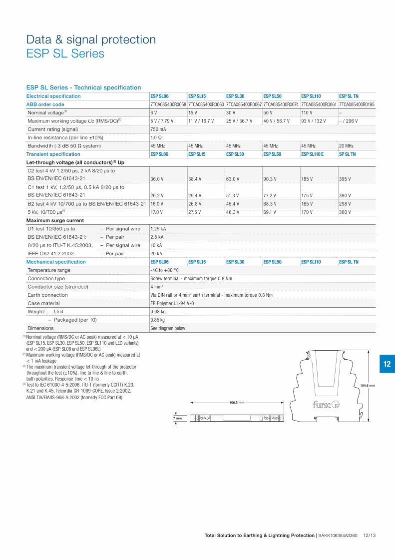
ESP SL Series - Technical specificationElectrical specification ESP SL06 ESP SL15 ESP SL30 ESP SL50 ESP SL110 ESP SL TN
ABB order code 7TCA085400R0058 7TCA085400R0063 7TCA085400R0067 7TCA085400R0074 7TCA085400R0061 7TCA085400R0195
Nominal voltage(1) 6 V 15 V 30 V 50 V 110 V –
Maximum working voltage Uc (RMS/DC)(2) 5 V / 7.79 V 11 V / 16.7 V 25 V / 36.7 V 40 V / 56.7 V 93 V / 132 V – / 296 V
Current rating (signal) 750 mA
In-line resistance (per line ±10%) 1.0 Ω
Bandwidth (-3 dB 50 Ω system) 45 MHz 45 MHz 45 MHz 45 MHz 45 MHz 20 MHz
Transient specification ESP SL06 ESP SL15 ESP SL30 ESP SL50 ESP SL110 E SP SL TN
Let-through voltage (all conductors)(3) Up
C2 test 4 kV 1.2/50 μs, 2 kA 8/20 μs to
BS EN/EN/IEC 61643-21 36.0 V 38.4 V 63.0 V 90.3 V 185 V 395 V
C1 test 1 kV, 1.2/50 μs, 0.5 kA 8/20 μs to
BS EN/EN/IEC 61643-21 26.2 V 29.4 V 51.3 V 77.2 V 175 V 390 V
B2 test 4 kV 10/700 μs to BS EN/EN/IEC 61643-21 16.0 V 26.8 V 45.4 V 68.3 V 165 V 298 V
5 kV, 10/700 μs(4) 17.0 V 27.5 V 46.3 V 69.1 V 170 V 300 V
Maximum surge current
D1 test 10/350 μs to – Per signal wire 1.25 kA
BS EN/EN/IEC 61643-21: – Per pair 2.5 kA
8/20 μs to ITU-T K.45:2003, – Per signal wire 10 kA
IEEE C62.41.2:2002: – Per pair 20 kA
Mechanical specification ESP SL06 ESP SL15 ESP SL30 ESP SL50 ESP SL110 ESP SL TN
Temperature range -40 to +80 °C
Connection type Screw terminal - maximum torque 0.8 Nm
Conductor size (stranded) 4 mm2
Earth connection Via DIN rail or 4 mm2 earth terminal - maximum torque 0.8 Nm
Case material FR Polymer UL-94 V-0
Weight: – Unit 0.08 kg
– Packaged (per 10) 0.85 kg
Dimensions See diagram below
(1) Nominal voltage (RMS/DC or AC peak) measured at < 10 μA (ESP SL15, ESP SL30, ESP SL50, ESP SL110 and LED variants) and < 200 μA (ESP SL06 and ESP SL06L)(2) Maximum working voltage (RMS/DC or AC peak) measured at < 1 mA leakage(3) The maximum transient voltage let-through of the protector throughout the test (±10%), line to line & line to earth, both polarities. Response time < 10 ns(4) Test to IEC 61000-4-5:2006, ITU-T (formerly CCITT) K.20, K.21 and K.45, Telcordia GR-1089-CORE, Issue 2:2002, ANSI TIA/EIA/IS-968-A:2002 (formerly FCC Part 68)
7 mm
104.6 mm
106.5 mm
2 S 1 2S E1
Data & signal protectionESP SL Series
12/14 Total Solution to Earthing & Lightning Protection | 9AKK106354A3360
12
Data & signal protectionESP SL X Series
Characteristics
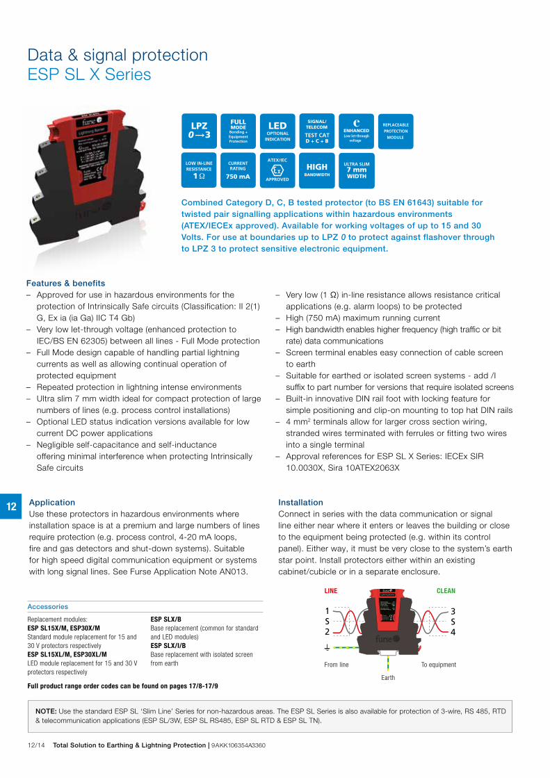
Combined Category D, C, B tested protector (to BS EN 61643) suitable for twisted pair signalling applications within hazardous environments (ATEX/IECEx approved). Available for working voltages of up to 15 and 30 Volts. For use at boundaries up to LPZ 0 to protect against flashover through to LPZ 3 to protect sensitive electronic equipment.
Features & benefits – Approved for use in hazardous environments for the
protection of Intrinsically Safe circuits (Classification: II 2(1)G, Ex ia (ia Ga) IIC T4 Gb)
– Very low let-through voltage (enhanced protection to IEC/BS EN 62305) between all lines - Full Mode protection
– Full Mode design capable of handling partial lightning currents as well as allowing continual operation of protected equipment
– Repeated protection in lightning intense environments – Ultra slim 7 mm width ideal for compact protection of large
numbers of lines (e.g. process control installations) – Optional LED status indication versions available for low
current DC power applications – Negligible self-capacitance and self-inductance
offering minimal interference when protecting Intrinsically Safe circuits
– Very low (1 Ω) in-line resistance allows resistance critical
applications (e.g. alarm loops) to be protected – High (750 mA) maximum running current – High bandwidth enables higher frequency (high traffic or bit
rate) data communications – Screen terminal enables easy connection of cable screen
to earth – Suitable for earthed or isolated screen systems - add /I
suffix to part number for versions that require isolated screens – Built-in innovative DIN rail foot with locking feature for
simple positioning and clip-on mounting to top hat DIN rails – 4 mm2 terminals allow for larger cross section wiring,
stranded wires terminated with ferrules or fitting two wires into a single terminal
– Approval references for ESP SL X Series: IECEx SIR 10.0030X, Sira 10ATEX2063X
ApplicationUse these protectors in hazardous environments where installation space is at a premium and large numbers of lines require protection (e.g. process control, 4-20 mA loops, fire and gas detectors and shut-down systems). Suitable for high speed digital communication equipment or systems with long signal lines. See Furse Application Note AN013.
InstallationConnect in series with the data communication or signal line either near where it enters or leaves the building or close to the equipment being protected (e.g. within its control panel). Either way, it must be very close to the system’s earth star point. Install protectors either within an existing cabinet/cubicle or in a separate enclosure.
NOTE: Use the standard ESP SL ‘Slim Line’ Series for non-hazardous areas. The ESP SL Series is also available for protection of 3-wire, RS 485, RTD & telecommunication applications (ESP SL/3W, ESP SL RS485, ESP SL RTD & ESP SL TN).
1S2
3S4
Lightning Barrier
From line
LINE CLEAN
EarthTo equipment
FurseWilford Road,Nottingham,NG2 1EB, UK C
lean
Lin
e
Nominal voltageMax working voltage, UcCurrent ratingIn-line resistance
Max surge currentLet-through voltage, Up
30V36.7V
750mA1.0Ω
20kA63V
From line To equipment
LINE CLEAN
Earth
Accessories
Replacement modules: ESP SL15X/M, ESP30X/M Standard module replacement for 15 and 30 V protectors respectivelyESP SL15XL/M, ESP30XL/MLED module replacement for 15 and 30 V protectors respectively
ESP SLX/B Base replacement (common for standard and LED modules)ESP SLX/I/B Base replacement with isolated screen from earth
Full product range order codes can be found on pages 17/8-17/9
Total Solution to Earthing & Lightning Protection | 9AKK106354A3360 12/15
12
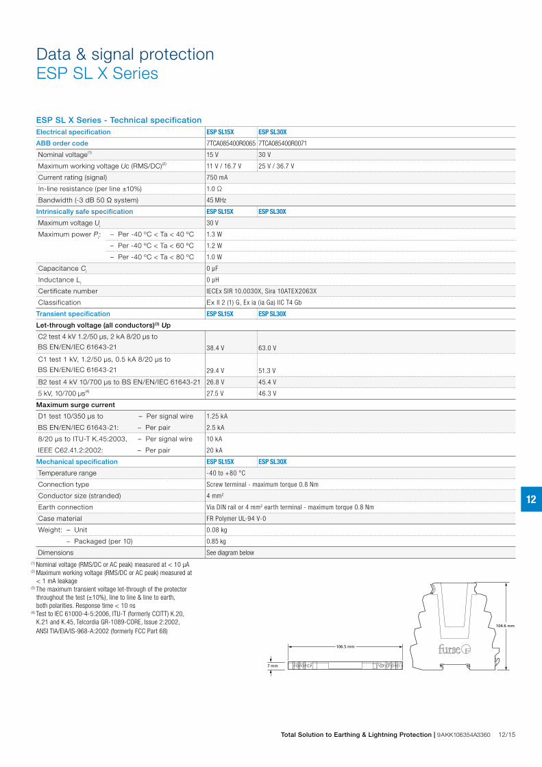
ESP SL X Series - Technical specificationElectrical specification ESP SL15X ESP SL30X
ABB order code 7TCA085400R0065 7TCA085400R0071
Nominal voltage(1) 15 V 30 V
Maximum working voltage Uc (RMS/DC)(2) 11 V / 16.7 V 25 V / 36.7 V
Current rating (signal) 750 mA
In-line resistance (per line ±10%) 1.0 Ω
Bandwidth (-3 dB 50 Ω system) 45 MHz
Intrinsically safe specification ESP SL15X ESP SL30X
Maximum voltage Ui 30 V
Maximum power Pi: – Per -40 ºC < Ta < 40 ºC 1.3 W
– Per -40 ºC < Ta < 60 ºC 1.2 W
– Per -40 ºC < Ta < 80 ºC 1.0 W
Capacitance Ci 0 μF
Inductance Li 0 μH
Certificate number IECEx SIR 10.0030X, Sira 10ATEX2063X
Classification Ex I I 2 (1) G, Ex ia (ia Ga) IIC T4 Gb
Transient specification ESP SL15X ESP SL30X
Let-through voltage (all conductors)(3) Up
C2 test 4 kV 1.2/50 μs, 2 kA 8/20 μs to
BS EN/EN/IEC 61643-21 38.4 V 63.0 V
C1 test 1 kV, 1.2/50 μs, 0.5 kA 8/20 μs to
BS EN/EN/IEC 61643-21 29.4 V 51.3 V
B2 test 4 kV 10/700 μs to BS EN/EN/IEC 61643-21 26.8 V 45.4 V
5 kV, 10/700 μs(4) 27.5 V 46.3 V
Maximum surge current
D1 test 10/350 μs to – Per signal wire 1.25 kA
BS EN/EN/IEC 61643-21: – Per pair 2.5 kA
8/20 μs to ITU-T K.45:2003, – Per signal wire 10 kA
IEEE C62.41.2:2002: – Per pair 20 kA
Mechanical specification ESP SL15X ESP SL30X
Temperature range -40 to +80 °C
Connection type Screw terminal - maximum torque 0.8 Nm
Conductor size (stranded) 4 mm2
Earth connection Via DIN rail or 4 mm2 earth terminal - maximum torque 0.8 Nm
Case material FR Polymer UL-94 V-0
Weight: – Unit 0.08 kg
– Packaged (per 10) 0.85 kg
Dimensions See diagram below(1) Nominal voltage (RMS/DC or AC peak) measured at < 10 μA (2) Maximum working voltage (RMS/DC or AC peak) measured at < 1 mA leakage(3) The maximum transient voltage let-through of the protector throughout the test (±10%), line to line & line to earth, both polarities. Response time < 10 ns(4) Test to IEC 61000-4-5:2006, ITU-T (formerly CCITT) K.20, K.21 and K.45, Telcordia GR-1089-CORE, Issue 2:2002, ANSI TIA/EIA/IS-968-A:2002 (formerly FCC Part 68)
7 mm
104.6 mm
106.5 mm
2 S 1 2S E1
Data & signal protectionESP SL X Series
12/16 Total Solution to Earthing & Lightning Protection | 9AKK106354A3360
12
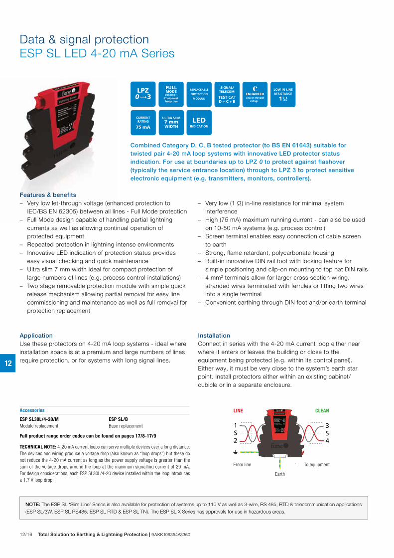
Combined Category D, C, B tested protector (to BS EN 61643) suitable for twisted pair 4-20 mA loop systems with innovative LED protector status indication. For use at boundaries up to LPZ 0 to protect against flashover (typically the service entrance location) through to LPZ 3 to protect sensitive electronic equipment (e.g. transmitters, monitors, controllers).
Data & signal protectionESP SL LED 4-20 mA Series
InstallationConnect in series with the 4-20 mA current loop either near where it enters or leaves the building or close to the equipment being protected (e.g. within its control panel). Either way, it must be very close to the system’s earth star point. Install protectors either within an existing cabinet/cubicle or in a separate enclosure.
Accessories
ESP SL30L/4-20/MModule replacement
ESP SL/BBase replacement
Full product range order codes can be found on pages 17/8-17/9
1S2
3S4
Lightning Barrier
From line
LINE CLEAN
EarthTo equipment
FurseWilford Road,Nottingham,NG2 1EB, UK C
lean
Lin
e
Nominal voltageMax working voltage, UcCurrent ratingIn-line resistance
Max surge currentLet-through voltage, Up
30V36.7V
750mA1.0Ω
20kA63V
From line To equipment
LINE CLEAN
Earth
TECHNICAL NOTE: 4-20 mA current loops can serve multiple devices over a long distance. The devices and wiring produce a voltage drop (also known as “loop drops”) but these do not reduce the 4-20 mA current as long as the power supply voltage is greater than the sum of the voltage drops around the loop at the maximum signalling current of 20 mA. For design considerations, each ESP SL30L/4-20 device installed within the loop introduces a 1.7 V loop drop.
Features & benefits – Very low let-through voltage (enhanced protection to
IEC/BS EN 62305) between all lines - Full Mode protection – Full Mode design capable of handling partial lightning
currents as well as allowing continual operation of protected equipment
– Repeated protection in lightning intense environments – Innovative LED indication of protection status provides
easy visual checking and quick maintenance – Ultra slim 7 mm width ideal for compact protection of
large numbers of lines (e.g. process control installations) – Two stage removable protection module with simple quick
release mechanism allowing partial removal for easy line commissioning and maintenance as well as full removal for protection replacement
– Very low (1 Ω) in-line resistance for minimal system interference
– High (75 mA) maximum running current - can also be used on 10-50 mA systems (e.g. process control)
– Screen terminal enables easy connection of cable screen to earth
– Strong, flame retardant, polycarbonate housing – Built-in innovative DIN rail foot with locking feature for
simple positioning and clip-on mounting to top hat DIN rails – 4 mm2 terminals allow for larger cross section wiring,
stranded wires terminated with ferrules or fitting two wires into a single terminal
– Convenient earthing through DIN foot and/or earth terminal
ApplicationUse these protectors on 4-20 mA loop systems - ideal where installation space is at a premium and large numbers of lines require protection, or for systems with long signal lines.
NOTE: The ESP SL ‘Slim Line’ Series is also available for protection of systems up to 110 V as well as 3-wire, RS 485, RTD & telecommunication applications (ESP SL/3W, ESP SL RS485, ESP SL RTD & ESP SL TN). The ESP SL X Series has approvals for use in hazardous areas.

Total Solution to Earthing & Lightning Protection | 9AKK106354A3360 12/17
12
ESP NEW SL LED 4-20 mA Series - Technical specificationElectrical specification ESP SL30L/4-20
ABB order code 7TCA085400R0070
Nominal voltage(1) 30 V
Maximum working voltage Uc (RMS/DC)(2) 25 V / 36.7 V
Current rating (signal)(3) 75 mA
In-line resistance (per line ±10%) 1.0 Ω
Series voltage drop(4) 1.7 V
Transient specification ESP SL30L/4-20
Let-through voltage (all conductors)(5) Up
C2 test 4 kV 1.2/50 μs, 2 kA 8/20 μs to
BS EN/EN/IEC 61643-21 63.0 V
C1 test 1 kV, 1.2/50 μs, 0.5 kA 8/20 μs to
BS EN/EN/IEC 61643-21 51.3 V
B2 test 4 kV 10/700 μs to BS EN/EN/IEC 61643-21 45.4 V
5 kV, 10/700 μs(6) 46.3 V
Maximum surge current
D1 test 10/350 μs to – Per signal wire 1.25 kA
BS EN/EN/IEC 61643-21: – Per pair 2.5 kA
8/20 μs to ITU-T K.45:2003, – Per signal wire 10 kA
IEEE C62.41.2:2002: – Per pair 20 kA
Mechanical specification ESP SL30L/4-20
Temperature range -40 to +80 °C
Connection type Screw terminal - maximum torque 0.8 Nm
Conductor size (stranded) 4 mm2
Earth connection Via DIN rail or 4 mm2 earth terminal - maximum torque 0.8 Nm
Case material FR Polymer UL-94 V-0
Weight: – Unit 0.08 kg
– Packaged (per 10) 0.85 kg
Dimensions See diagram below(1) Nominal voltage (RMS/DC or AC peak) measured at < 10 μA (2) Maximum working voltage (RMS/DC or AC peak) measured at < 1 mA leakage(3) The minimum current for LED indicator operation is 2 mA(4) At 20 mA(5) The maximum transient voltage let-through of the protector throughout the test (±10%), line to line & line to earth, both polarities. Response time < 10 ns(6) Test to IEC 61000-4-5:2006, ITU-T (formerly CCITT) K.20, K.21 and K.45, Telcordia GR-1089-CORE, Issue 2:2002, ANSI TIA/EIA/IS-968-A:2002 (formerly FCC Part 68)
7 mm
104.6 mm
106.5 mm
2 S 1 2S E1
Data & signal protectionESP SL LED 4-20 mA Series

12/18 Total Solution to Earthing & Lightning Protection | 9AKK106354A3360
12
Combined Category D, C, B tested protector (to BS EN 61643) suitable for 3-wire signalling applications which require either a lower in-line resistance, an increased current and/or higher bandwidth. Also suitable for DC power applications less than 0.5 Amps. Available for working voltages of up to 6, 15, 30, 50 and 110 Volts. For use at boundaries up to LPZ 0 to protect against flashover (typically the service entrance location) through to LPZ 3 to protect sensitive electronic equipment.
Data & signal protectionESP SL 3-Wire Series
InstallationConnect in series with the data communication or signal line either near where it enters or leaves the building or close to the equipment being protected (e.g. within its control panel). Either way, it must be very close to the system’s earth star point. Install protectors either within an existing cabinet/cubicle or in a separate enclosure.
Accessories
Replacement modules:ESP SLXX/3W/MStandard module replacement where XX is voltage rating (06, 15, 30, 50 or 110)
ESP SL/3W/BBase replacement
Full product range order codes can be found on pages 17/8-17/9
456
123
Lightning Barrier
From line
LINE CLEAN
EarthTo equipment
FurseWilford Road,Nottingham,NG2 1EB, UK C
lean
Line
30V37.8V
750mA1.0Ω
10kA43.5V
Nominal voltageMax working voltage, UcCurrent ratingIn- line resistance
Max surge currentLet- through voltage, Up
From line To equipment
LINE CLEAN
Earth
Features & benefits – Very low let-through voltage (enhanced protection to
IEC/BS EN 62305) between all lines - Full Mode protection – Full Mode design capable of handling partial lightning
currents as well as allowing continual operation of protected equipment
– Repeated protection in lightning intense environments – Ultra slim 7 mm width ideal for compact protection of large
numbers of lines (e.g. process control installations) – Two stage removable protection module with simple quick
release mechanism allowing partial removal for easy line commissioning and maintenance as well as full removal for protection replacement
– Very low (1 Ω) in-line resistance allows resistance critical applications (e.g. alarm loops) to be protected
– High (500 mA) maximum running current – High bandwidth enables higher frequency (high traffic or
bit rate) data communications – Strong, flame retardant, polycarbonate housing – Built-in innovative DIN rail foot with locking feature for
simple positioning and clip-on mounting to top hat DIN rails – 4 mm2 terminals allow for larger cross section wiring,
stranded wires terminated with ferrules or fitting two wires into a single terminal
– Convenient earthing through DIN foot and/or earth terminal
ApplicationUse these protectors for 3-wire systems where installation space is at a premium and large numbers of lines require protection (e.g. process control, high speed digital communication equipment or systems with long signal lines).
NOTE: The ESP SL ‘Slim Line’ Series is also available for protection of 2-wire systems up to 110 V, RS 485, RTD and telecommunication applications (ESP SL Series, ESP SL RS485, ESP SL RTD and ESP SL TN). The ESP SL X Series has approvals for use in hazardous areas.
Total Solution to Earthing & Lightning Protection | 9AKK106354A3360 12/19
12
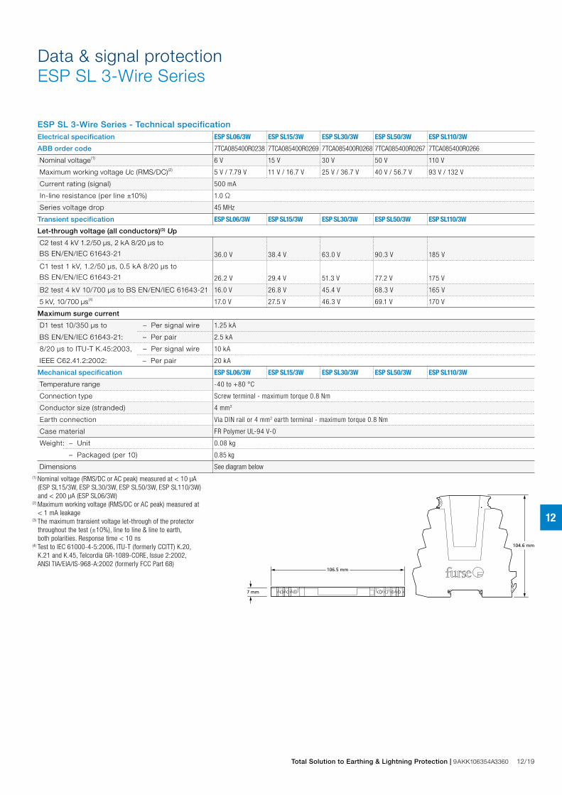
ESP SL 3-Wire Series - Technical specificationElectrical specification ESP SL06/3W ESP SL15/3W ESP SL30/3W ESP SL50/3W ESP SL110/3W
ABB order code 7TCA085400R0238 7TCA085400R0269 7TCA085400R0268 7TCA085400R0267 7TCA085400R0266
Nominal voltage(1) 6 V 15 V 30 V 50 V 110 V
Maximum working voltage Uc (RMS/DC)(2) 5 V / 7.79 V 11 V / 16.7 V 25 V / 36.7 V 40 V / 56.7 V 93 V / 132 V
Current rating (signal) 500 mA
In-line resistance (per line ±10%) 1.0 Ω
Series voltage drop 45 MHz
Transient specification ESP SL06/3W ESP SL15/3W ESP SL30/3W ESP SL50/3W ESP SL110/3W
Let-through voltage (all conductors)(3) Up
C2 test 4 kV 1.2/50 μs, 2 kA 8/20 μs to
BS EN/EN/IEC 61643-21 36.0 V 38.4 V 63.0 V 90.3 V 185 V
C1 test 1 kV, 1.2/50 μs, 0.5 kA 8/20 μs to
BS EN/EN/IEC 61643-21 26.2 V 29.4 V 51.3 V 77.2 V 175 V
B2 test 4 kV 10/700 μs to BS EN/EN/IEC 61643-21 16.0 V 26.8 V 45.4 V 68.3 V 165 V
5 kV, 10/700 μs(4) 17.0 V 27.5 V 46.3 V 69.1 V 170 V
Maximum surge current
D1 test 10/350 μs to – Per signal wire 1.25 kA
BS EN/EN/IEC 61643-21: – Per pair 2.5 kA
8/20 μs to ITU-T K.45:2003, – Per signal wire 10 kA
IEEE C62.41.2:2002: – Per pair 20 kA
Mechanical specification ESP SL06/3W ESP SL15/3W ESP SL30/3W ESP SL50/3W ESP SL110/3W
Temperature range -40 to +80 °C
Connection type Screw terminal - maximum torque 0.8 Nm
Conductor size (stranded) 4 mm2
Earth connection Via DIN rail or 4 mm2 earth terminal - maximum torque 0.8 Nm
Case material FR Polymer UL-94 V-0
Weight: – Unit 0.08 kg
– Packaged (per 10) 0.85 kg
Dimensions See diagram below(1) Nominal voltage (RMS/DC or AC peak) measured at < 10 μA (ESP SL15/3W, ESP SL30/3W, ESP SL50/3W, ESP SL110/3W) and < 200 μA (ESP SL06/3W)(2) Maximum working voltage (RMS/DC or AC peak) measured at < 1 mA leakage(3) The maximum transient voltage let-through of the protector throughout the test (±10%), line to line & line to earth, both polarities. Response time < 10 ns(4) Test to IEC 61000-4-5:2006, ITU-T (formerly CCITT) K.20, K.21 and K.45, Telcordia GR-1089-CORE, Issue 2:2002, ANSI TIA/EIA/IS-968-A:2002 (formerly FCC Part 68)
7 mm
104.6 mm
106.5 mm
2 S 1 2S E1
Data & signal protectionESP SL 3-Wire Series

12/20 Total Solution to Earthing & Lightning Protection | 9AKK106354A3360
12
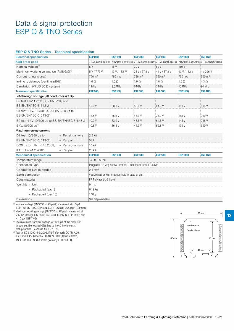
Combined Category D, C, B tested protector (to BS EN 61643) suitable for 4 twisted pair lines. Available for working voltages of up to 6, 15, 30, 50 and 110 Volts. ESP TNQ suitable for Broadband, POTS, dial-up, T1/E1, lease line and *DSL telephone applications. For use at boundaries up to LPZ 0 to protect against flashover (typically the service entrance location) through to LPZ 3 to protect sensitive
Data & signal protectionESP Q & TNQ Series
Accessories
For suitable enclosures for the ESP Q & TNQ Series, please contact us.
Full product range order codes can be found on pages 17/8-17/9
ESP 06Q, ESP 15Q, ESP 30Q, ESP 50Q, ESP 110Q and ESP TNQ installed in series (in-line)
Fromline
To equipment
DIRTY CLEAN
Earth
NOTE: The ESP Q Series is also available for protection of RS 485 and RTD applications (ESP RS485Q, ESP RTDQ). Protectors for individual data and signal lines are available (ESP D Series and Slim Line ESP SL Series), or ready-boxed to IP66 (ESP **D/BX etc). Alternatively, for individual protectors with higher current or bandwidth use the ESP E and ESP H Series.
InstallationConnect in series with the signal or data line either near where it enters or leaves the building or close to the equipment being protected. Install in a cabinet/cubicle close to the system’s earth star point.
Features & benefits – Very low let-through voltage (enhanced protection to
IEC/BS EN 62305) between all lines - Full Mode protection – Full Mode design capable of handling partial lightning
currents as well as allowing continual operation of protected equipment
– Repeated protection in lightning intense environments – Almost twice as space efficient as smallest competitor – Standard DIN module (18 mm) depth – Removable (plug-in) terminals allow pre-wiring of cable
looms, for easier installation – Suitable for earthed or isolated screen systems – Built-in DIN rail foot for clip-on mounting to top hat or
G DIN rails – Optional flat mounting on side – 2.5 mm2 terminals allow for larger cross section wiring,
stranded wires terminated with ferrules or fitting two wires into a single terminal
– Very low resistance to minimizes unwanted signal strength reductions
– Strong, flame retardant, ABS housing – Colour coded terminals (grey for line, green for clean) give
a quick and easy installation check – Screen terminal enables easy connection of cable screen
to earth – Simple, yet substantial, connection to earth via DIN rail – ESP TNQ is suitable for telecommunication applications
in accordance with Telcordia and ANSI Standards (see Application Note AN005)
– Available as a ‘UL Listed’ version, add /UL to part code (ESP 06Q, ESP 15Q, ESP 30Q and ESP 50Q only)
ApplicationUse these protectors where installation space is at a premium and large numbers of lines require protection.
Total Solution to Earthing & Lightning Protection | 9AKK106354A3360 12/21
12
ESP Q & TNQ Series - Technical specificationElectrical specification ESP 06Q ESP 15Q ESP 30Q ESP 50Q ESP 110Q ESP TNQ
ABB order code 7TCA085400R0087 7TCA085400R0098 7TCA085400R0107 7TCA085400R0118 7TCA085400R0088 7TCA085400R0183
Nominal voltage(1) 6 V 15 V 30 V 50 V 110 V –
Maximum working voltage Uc (RMS/DC)(2) 5 V / 7.79 V 13 V / 18.8 V 26 V / 37.8 V 41 V / 57.8 V 93 V / 132 V – / 296 V
Current rating (signal) 750 mA 750 mA 750 mA 750 mA 750 mA 300 mA
In-line resistance (per line ±10%) 1.0 Ω 1.0 Ω 1.0 Ω 1.0 Ω 1.0 Ω 4.3 Ω
Bandwidth (-3 dB 50 Ω system) 1 MHz 2.5 MHz 6 MHz 5 MHz 15 MHz 20 MHz
Transient specification ESP 06Q ESP 15Q ESP 30Q ESP 50Q ESP 110Q ESP TNQ
Let-through voltage (all conductors)(3) Up
C2 test 4 kV 1.2/50 μs, 2 kA 8/20 μs to
BS EN/EN/IEC 61643-21 15.0 V 28.0 V 53.0 V 84.0 V 188 V 395 V
C1 test 1 kV, 1.2/50 μs, 0.5 kA 8/20 μs to
BS EN/EN/IEC 61643-21 12.5 V 26.5 V 48.0 V 76.0 V 175 V 390 V
B2 test 4 kV 10/700 μs to BS EN/EN/IEC 61643-21 10.0 V 23.0 V 43.5 V 64.5 V 145 V 298 V
5 kV, 10/700 μs(4) 10.8 V 26.2 V 44.3 V 65.8 V 150 V 300 V
Maximum surge current
D1 test 10/350 μs to – Per signal wire 2.5 kA
BS EN/EN/IEC 61643-21: – Per pair 5 kA
8/20 μs to ITU-T K.45:2003, – Per signal wire 10 kA
IEEE C62.41.2:2002: – Per pair 20 kA
Mechanical specification ESP 06Q ESP 15Q ESP 30Q ESP 50Q ESP 110Q ESP TNQ
Temperature range -40 to +80 °C
Connection type Pluggable 12 way screw terminal - maximum torque 0.6 Nm
Conductor size (stranded) 2.5 mm2
Earth connection Via DIN rail or M5 threaded hole in base of unit
Case material FR Polymer UL-94 V-0
Weight: – Unit 0.1 kg
– Packaged (each) 0.12 kg
– Packaged (per 10) 1.3 kg
Dimensions See diagram below(1) Nominal voltage (RMS/DC or AC peak) measured at < 5 μA (ESP 15Q, ESP 30Q, ESP 50Q, ESP 110Q) and < 200 μA (ESP 06Q)(2) Maximum working voltage (RMS/DC or AC peak) measured at < 5 mA leakage (ESP 15Q, ESP 30Q, ESP 50Q, ESP 110Q) and < 10 μA (ESP TNQ)(3) The maximum transient voltage let-through of the protector throughout the test (±10%), line to line & line to earth, both polarities. Response time < 10 ns(4) Test to IEC 61000-4-5:2006, ITU-T (formerly CCITT) K.20, K.21 and K.45, Telcordia GR-1089-CORE, Issue 2:2002, ANSI TIA/EIA/IS-968-A:2002 (formerly FCC Part 68)
95 mm
69 mm
42 mm
M3 clearance
Depth: 18 mm
87 mm
Data & signal protectionESP Q & TNQ Series
12/22 Total Solution to Earthing & Lightning Protection | 9AKK106354A3360
12
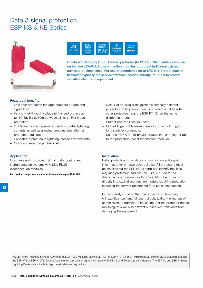
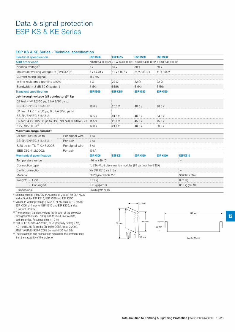
Combined Category D, C, B tested protector (to BS EN 61643) suitable for use on ten line LSA-PLUS disconnection modules to protect individual twisted pair data or signal lines. For use at boundaries up to LPZ 0 to protect against flashover (typically the service entrance location) through to LPZ 3 to protect sensitive electronic equipment.
Data & signal protectionESP KS & KE Series
InstallationInstall protectors on all data communication and signal lines that enter or leave each building. All protectors must be installed via the ESP KE10 earth bar. Identify the lines requiring protection and clip the ESP KE10 on to the disconnection modules’ earth points. Plug the protector directly into each disconnection module requiring protection (ensuring the correct orientation) for a series connection.
In the unlikely situation that the protector is damaged, it will sacrifice itself and fail short circuit, taking the line out of commission. In addition to indicating that the protector needs replacing, this will also prevent subsequent transients from damaging the equipment.
NOTE: For PSTN and U interface ISDN lines on LSA-PLUS modules, use the ESP KT1 or ESP K10T1. For S/T interface ISDN lines on LSA-PLUS modules, use the ESP KT2 or ESP K10T2. For individual twisted pair data or signal lines, use the ESP D, E or H Series Lightning Barriers. The ESP SL and ESP Q Series Lightning Barriers are suitable for high density data and signal lines.
Features & benefits – Low cost protection for large numbers of data and
signal lines – Very low let-through voltage (enhanced protection
to IEC/BS EN 62305) between all lines - Full Mode protection
– Full Mode design capable of handling partial lightning currents as well as allowing continual operation of protected equipment
– Repeated protection in lightning intense environments – Quick and easy plug-in installation
– Colour of housing distinguishes electrically different protectors to help avoid confusion when installed with other protectors (e.g. the ESP KT1/2) on the same distribution frame
– Protect only the lines you need – Ridged finger holds make it easy to obtain a firm grip
for installation or removal – Use the ESP KE10 to provide trouble free earthing for up
to ten protectors (per disconnection module)
ApplicationUse these units to protect signal, data, control and instrumentation systems with LSA-PLUS disconnection modules.
Full product range order codes can be found on pages 17/8-17/9
Total Solution to Earthing & Lightning Protection | 9AKK106354A3360 12/23
12
ESP KS & KE Series - Technical specificationElectrical specification ESP KS06 ESP KS15 ESP KS30 ESP KS50
ABB order code 7TCA085400R0029 7TCA085400R0030 7TCA085400R0032 7TCA085400R0033
Nominal voltage(1) 6 V 15 V 30 V 50 V
Maximum working voltage Uc (RMS/DC)(2) 5 V / 7.79 V 11 V / 16.7 V 24 V / 33.4 V 41 V / 58 V
Current rating (signal) 150 mA
In-line resistance (per line ±10%) 1 Ω 22 Ω 22 Ω 22 Ω
Bandwidth (-3 dB 50 Ω system) 2 MHz 5 MHz 5 MHz 5 MHz
Transient specification ESP KS06 ESP KS15 ESP KS30 ESP KS50
Let-through voltage (all conductors)(3) Up
C2 test 4 kV 1.2/50 μs, 2 kA 8/20 μs to
BS EN/EN/IEC 61643-21 16.0 V 26.5 V 48.0 V 98.0 V
C1 test 1 kV, 1.2/50 μs, 0.5 kA 8/20 μs to
BS EN/EN/IEC 61643-21 14.5 V 24.0 V 46.5 V 84.5 V
B2 test 4 kV 10/700 μs to BS EN/EN/IEC 61643-21 11.5 V 23.0 V 45.0 V 75.0 V
5 kV, 10/700 μs(4) 12.0 V 24.4 V 48.8 V 80.0 V
Maximum surge current(5)
D1 test 10/350 μs to – Per signal wire 1 kA
BS EN/EN/IEC 61643-21: – Per pair 2 kA
8/20 μs to ITU-T K.45:2003, – Per signal wire 5 kA
IEEE C62.41.2:2002: – Per pair 10 kA
Mechanical specification ESP KS06 ESP KS1 ESP KS30 ESP KS50 ESP KE10
Temperature range -40 to +80 °C –
Connection type To LSA-PLUS disconnection modules (BT part number 237A)
Earth connection Via ESP KE10 earth bar –
Material FR Polymer UL-94 V-0 Stainless Steel
Weight: – Unit 0.01 kg 0.01 kg
– Packaged 0.10 kg (per 10) 0.12 kg (per 10)
Dimensions See diagram below(1) Nominal voltage (RMS/DC or AC peak) at 200 μA for ESP KS06 and at 5 μA for ESP KS15, ESP KS30 and ESP KS50(2) Maximum working voltage (RMS/DC or AC peak) at 10 mA for ESP KS06, at 1 mA for ESP KS15 and ESP KS30, and at 5 μA for ESP KS50.(3) The maximum transient voltage let-through of the protector throughout the test (±10%), line to line & line to earth, both polarities. Response time < 10 ns(4) Test to IEC 61000-4-5:2006, ITU-T (formerly CCITT) K.20, K.21 and K.45, Telcordia GR-1089-CORE, Issue 2:2002, ANSI TIA/EIA/IS-968-A:2002 (formerly FCC Part 68)(5) The installation and connections external to the protector may limit the capability of the protector
22 mm
Depth: 21 mm
110 mm
9.5 mm
52 mm
20 mm
40 mm
Data & signal protectionESP KS & KE Series

12/24 Total Solution to Earthing & Lightning Protection | 9AKK106354A3360
12
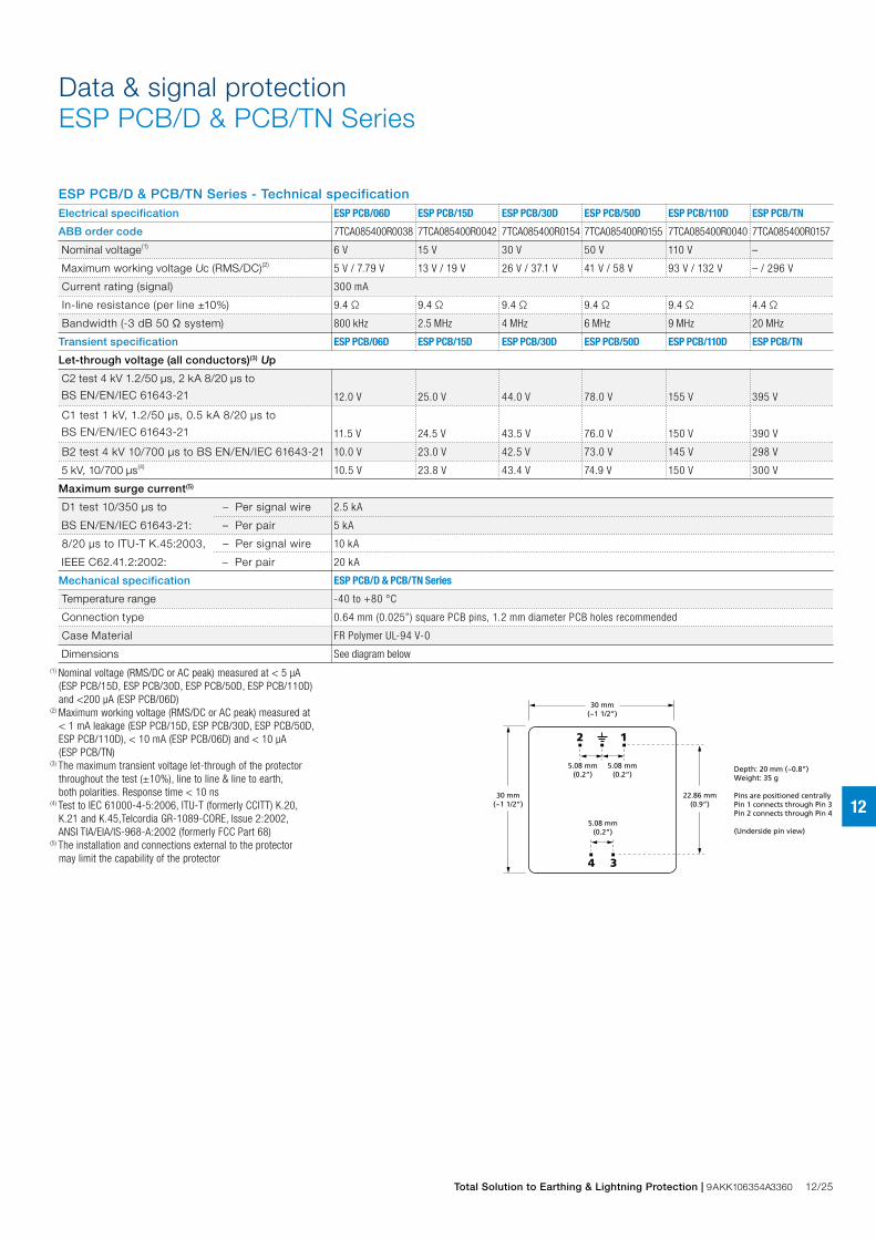
Combined Category D, C, B tested protector (to BS EN 61643) for ‘through hole’ mounting directly onto the PCB of data communication, signal or telephone equipment. Available for working voltages of up to 110 Volts. ESP PCB/TN suitable for Broadband, POTS, dial-up, T1/E1, lease line and *DSL telephone applications. For use at boundaries up to LPZ 0 to protect against flashover (typically the service entrance location) through to LPZ 3 to protect sensitive electronic equipment.
Data & signal protectionESP PCB/D & PCB/TN Series
InstallationConnect in series, soldering pins direct onto PCB. Tracks to line and earth pins should be as wide as practical (see Furse Application Note AN003). Dirty (line) tracks should be routed parallel and as close together as possible. This should also be implemented on clean tracks, however clean tracks should never be routed close and parallel to line tracks or dirty barrier earth connections as transients can be re-introduced after the protector due to electromagnetic coupling.
The use of an earth layer or plane is highly recommended as this reduces the electromagnetic field produced by a transient discharging to earth considerably, and hence the chance of the transient being picked up on clean tracks.
Full product range order codes can be found on pages 17/8-17/9
Maximum line to clean separation. Large input tracks and pads (using top and bottom copper layers). Earth pin is bonded to an earth layer/plane.
Clean
1 3
42
LineLINE CLEAN
All dirty (line) incoming tracks are separated from the clean output tracks, individual line and clean tracks are routed close together. Earth pins are bonded to an earth layer/plane.
Line
Clean Clean
3
4
3
4
1
2
1
2
ESP PCB/**
3
4
1
2
ESP PCB/**
1 3
42
CLEAN CLEAN
LINE
Features & benefits – Suitable for wave soldering – Very low let-through voltage (enhanced protection
to IEC/BS EN 62305) between all lines - Full Mode protection
– Full Mode design capable of handling partial lightning currents as well as allowing continual operation of protected equipment
– Repeated protection in lightning intense environments
– Low in-line resistance minimizes unnecessary reductions in signal strength
– 2 pin clean end and 3 pin line end to ensure correct insertion
– ESP PCB/TN is suitable for telecommunication applications in accordance with Telcordia and ANSI Standards (see Application Note AN005)
Total Solution to Earthing & Lightning Protection | 9AKK106354A3360 12/25
12
ESP PCB/D & PCB/TN Series - Technical specificationElectrical specification ESP PCB/06D ESP PCB/15D ESP PCB/30D ESP PCB/50D ESP PCB/110D ESP PCB/TN
ABB order code 7TCA085400R0038 7TCA085400R0042 7TCA085400R0154 7TCA085400R0155 7TCA085400R0040 7TCA085400R0157
Nominal voltage(1) 6 V 15 V 30 V 50 V 110 V –
Maximum working voltage Uc (RMS/DC)(2) 5 V / 7.79 V 13 V / 19 V 26 V / 37.1 V 41 V / 58 V 93 V / 132 V – / 296 V
Current rating (signal) 300 mA
In-line resistance (per line ±10%) 9.4 Ω 9.4 Ω 9.4 Ω 9.4 Ω 9.4 Ω 4.4 Ω
Bandwidth (-3 dB 50 Ω system) 800 kHz 2.5 MHz 4 MHz 6 MHz 9 MHz 20 MHz
Transient specification ESP PCB/06D ESP PCB/15D ESP PCB/30D ESP PCB/50D ESP PCB/110D ESP PCB/TN
Let-through voltage (all conductors)(3) Up
C2 test 4 kV 1.2/50 μs, 2 kA 8/20 μs to
BS EN/EN/IEC 61643-21 12.0 V 25.0 V 44.0 V 78.0 V 155 V 395 V
C1 test 1 kV, 1.2/50 μs, 0.5 kA 8/20 μs to
BS EN/EN/IEC 61643-21 11.5 V 24.5 V 43.5 V 76.0 V 150 V 390 V
B2 test 4 kV 10/700 μs to BS EN/EN/IEC 61643-21 10.0 V 23.0 V 42.5 V 73.0 V 145 V 298 V
5 kV, 10/700 μs(4) 10.5 V 23.8 V 43.4 V 74.9 V 150 V 300 V
Maximum surge current(5)
D1 test 10/350 μs to – Per signal wire 2.5 kA
BS EN/EN/IEC 61643-21: – Per pair 5 kA
8/20 μs to ITU-T K.45:2003, – Per signal wire 10 kA
IEEE C62.41.2:2002: – Per pair 20 kA
Mechanical specification ESP PCB/D & PCB/TN Series
Temperature range -40 to +80 °C
Connection type 0.64 mm (0.025”) square PCB pins, 1.2 mm diameter PCB holes recommended
Case Material FR Polymer UL-94 V-0
Dimensions See diagram below(1) Nominal voltage (RMS/DC or AC peak) measured at < 5 μA (ESP PCB/15D, ESP PCB/30D, ESP PCB/50D, ESP PCB/110D) and <200 μA (ESP PCB/06D)(2) Maximum working voltage (RMS/DC or AC peak) measured at < 1 mA leakage (ESP PCB/15D, ESP PCB/30D, ESP PCB/50D, ESP PCB/110D), < 10 mA (ESP PCB/06D) and < 10 μA (ESP PCB/TN)(3) The maximum transient voltage let-through of the protector throughout the test (±10%), line to line & line to earth, both polarities. Response time < 10 ns(4) Test to IEC 61000-4-5:2006, ITU-T (formerly CCITT) K.20, K.21 and K.45,Telcordia GR-1089-CORE, Issue 2:2002, ANSI TIA/EIA/IS-968-A:2002 (formerly FCC Part 68)(5) The installation and connections external to the protector may limit the capability of the protector
30 mm(~1 1/2”)
22.86 mm(0.9”)
12
4 3
5.08 mm(0.2”)
5.08 mm(0.2”)
5.08 mm(0.2”)
Depth: 20 mm (~0.8”)Weight: 35 g
Pins are positioned centrallyPin 1 connects through Pin 3Pin 2 connects through Pin 4
(Underside pin view)
30 mm(~1 1/2”)
Data & signal protectionESP PCB/D & PCB/TN Series
12/26 Total Solution to Earthing & Lightning Protection | 9AKK106354A3360
12
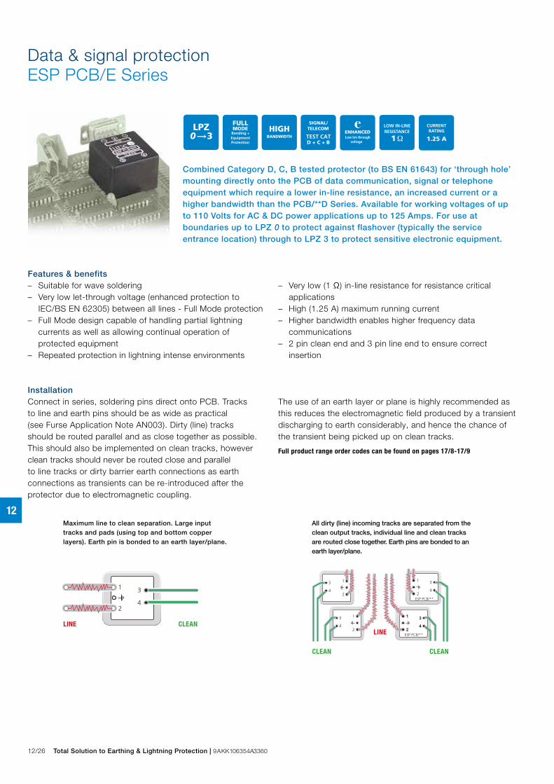
Combined Category D, C, B tested protector (to BS EN 61643) for ‘through hole’ mounting directly onto the PCB of data communication, signal or telephone equipment which require a lower in-line resistance, an increased current or a higher bandwidth than the PCB/**D Series. Available for working voltages of up to 110 Volts for AC & DC power applications up to 125 Amps. For use at boundaries up to LPZ 0 to protect against flashover (typically the service entrance location) through to LPZ 3 to protect sensitive electronic equipment.
Data & signal protectionESP PCB/E Series
InstallationConnect in series, soldering pins direct onto PCB. Tracks to line and earth pins should be as wide as practical (see Furse Application Note AN003). Dirty (line) tracks should be routed parallel and as close together as possible. This should also be implemented on clean tracks, however clean tracks should never be routed close and parallel to line tracks or dirty barrier earth connections as earth connections as transients can be re-introduced after the protector due to electromagnetic coupling.
The use of an earth layer or plane is highly recommended as this reduces the electromagnetic field produced by a transient discharging to earth considerably, and hence the chance of the transient being picked up on clean tracks.
Full product range order codes can be found on pages 17/8-17/9
Maximum line to clean separation. Large input tracks and pads (using top and bottom copper layers). Earth pin is bonded to an earth layer/plane.
All dirty (line) incoming tracks are separated from the clean output tracks, individual line and clean tracks are routed close together. Earth pins are bonded to an earth layer/plane.
Clean
1 3
42
LineLINE CLEANLine
Clean Clean
3
4
3
4
1
2
1
2
ESP PCB/**
3
4
1
2
ESP PCB/**
1 3
42
CLEAN CLEAN
LINE
Features & benefits – Suitable for wave soldering – Very low let-through voltage (enhanced protection to
IEC/BS EN 62305) between all lines - Full Mode protection – Full Mode design capable of handling partial lightning
currents as well as allowing continual operation of protected equipment
– Repeated protection in lightning intense environments
– Very low (1 Ω) in-line resistance for resistance critical applications
– High (1.25 A) maximum running current – Higher bandwidth enables higher frequency data
communications – 2 pin clean end and 3 pin line end to ensure correct
insertion
Total Solution to Earthing & Lightning Protection | 9AKK106354A3360 12/27
12
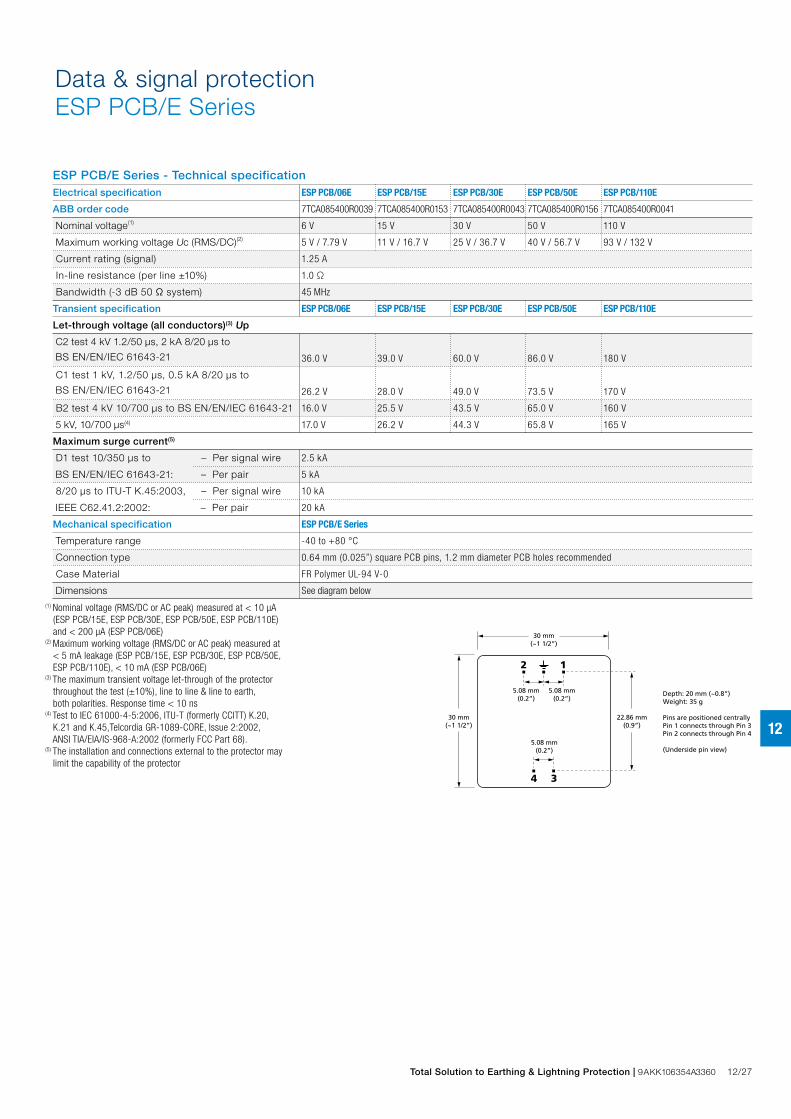
ESP PCB/E Series - Technical specificationElectrical specification ESP PCB/06E ESP PCB/15E ESP PCB/30E ESP PCB/50E ESP PCB/110E
ABB order code 7TCA085400R0039 7TCA085400R0153 7TCA085400R0043 7TCA085400R0156 7TCA085400R0041
Nominal voltage(1) 6 V 15 V 30 V 50 V 110 V
Maximum working voltage Uc (RMS/DC)(2) 5 V / 7.79 V 11 V / 16.7 V 25 V / 36.7 V 40 V / 56.7 V 93 V / 132 V
Current rating (signal) 1.25 A
In-line resistance (per line ±10%) 1.0 Ω
Bandwidth (-3 dB 50 Ω system) 45 MHz
Transient specification ESP PCB/06E ESP PCB/15E ESP PCB/30E ESP PCB/50E ESP PCB/110E
Let-through voltage (all conductors)(3) Up
C2 test 4 kV 1.2/50 μs, 2 kA 8/20 μs to
BS EN/EN/IEC 61643-21 36.0 V 39.0 V 60.0 V 86.0 V 180 V
C1 test 1 kV, 1.2/50 μs, 0.5 kA 8/20 μs to
BS EN/EN/IEC 61643-21 26.2 V 28.0 V 49.0 V 73.5 V 170 V
B2 test 4 kV 10/700 μs to BS EN/EN/IEC 61643-21 16.0 V 25.5 V 43.5 V 65.0 V 160 V
5 kV, 10/700 μs(4) 17.0 V 26.2 V 44.3 V 65.8 V 165 V
Maximum surge current(5)
D1 test 10/350 μs to – Per signal wire 2.5 kA
BS EN/EN/IEC 61643-21: – Per pair 5 kA
8/20 μs to ITU-T K.45:2003, – Per signal wire 10 kA
IEEE C62.41.2:2002: – Per pair 20 kA
Mechanical specification ESP PCB/E Series
Temperature range -40 to +80 °C
Connection type 0.64 mm (0.025”) square PCB pins, 1.2 mm diameter PCB holes recommended
Case Material FR Polymer UL-94 V-0
Dimensions See diagram below(1) Nominal voltage (RMS/DC or AC peak) measured at < 10 μA (ESP PCB/15E, ESP PCB/30E, ESP PCB/50E, ESP PCB/110E) and < 200 μA (ESP PCB/06E)(2) Maximum working voltage (RMS/DC or AC peak) measured at < 5 mA leakage (ESP PCB/15E, ESP PCB/30E, ESP PCB/50E, ESP PCB/110E), < 10 mA (ESP PCB/06E)(3) The maximum transient voltage let-through of the protector throughout the test (±10%), line to line & line to earth, both polarities. Response time < 10 ns(4) Test to IEC 61000-4-5:2006, ITU-T (formerly CCITT) K.20, K.21 and K.45,Telcordia GR-1089-CORE, Issue 2:2002, ANSI TIA/EIA/IS-968-A:2002 (formerly FCC Part 68).(5) The installation and connections external to the protector may limit the capability of the protector
30 mm(~1 1/2”)
22.86 mm(0.9”)
12
4 3
5.08 mm(0.2”)
5.08 mm(0.2”)
5.08 mm(0.2”)
Depth: 20 mm (~0.8”)Weight: 35 g
Pins are positioned centrallyPin 1 connects through Pin 3Pin 2 connects through Pin 4
(Underside pin view)
30 mm(~1 1/2”)
Data & signal protectionESP PCB/E Series
12/28 Total Solution to Earthing & Lightning Protection | 9AKK106354A3360
12
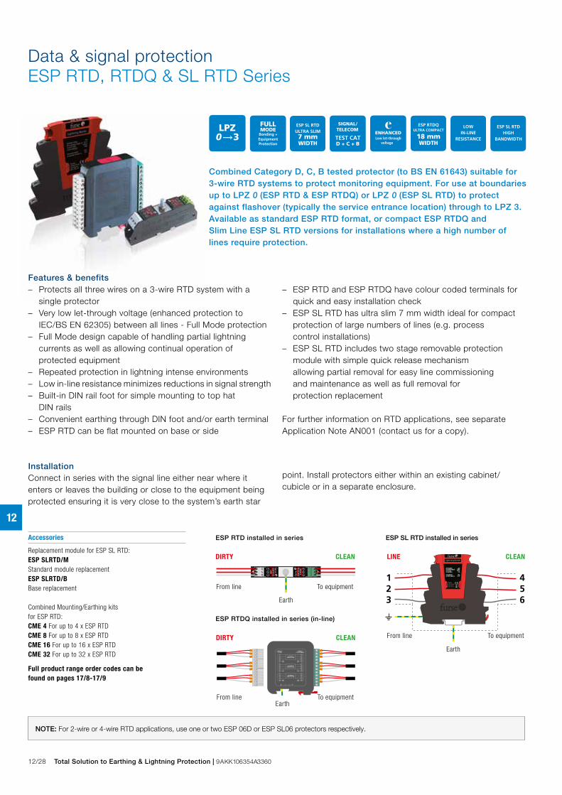
Data & signal protectionESP RTD, RTDQ & SL RTD Series
InstallationConnect in series with the signal line either near where it enters or leaves the building or close to the equipment being protected ensuring it is very close to the system’s earth star
point. Install protectors either within an existing cabinet/cubicle or in a separate enclosure.
Accessories
Replacement module for ESP SL RTD:ESP SLRTD/MStandard module replacementESP SLRTD/BBase replacement
Combined Mounting/Earthing kitsfor ESP RTD:CME 4 For up to 4 x ESP RTDCME 8 For up to 8 x ESP RTDCME 16 For up to 16 x ESP RTDCME 32 For up to 32 x ESP RTD
Full product range order codes can be found on pages 17/8-17/9
ESP RTDQ installed in series (in-line)
ESP SL RTD installed in series
456
123
Lightning Barrier
From line
LINE CLEAN
EarthTo equipment
FurseWilford Road,Nottingham,NG2 1EB, UK C
lean
Line
30V37.8V
750mA1.0Ω
10kA43.5V
Nominal voltageMax working voltage, UcCurrent ratingIn- line resistance
Max surge currentLet- through voltage, Up
From line To equipment
LINE CLEAN
Earth
ESP RTD installed in series
DIRTY CLEAN
From line To equipment
Earth
DIRTY CLEAN
From line To equipmentEarth
Features & benefits – Protects all three wires on a 3-wire RTD system with a
single protector – Very low let-through voltage (enhanced protection to
IEC/BS EN 62305) between all lines - Full Mode protection – Full Mode design capable of handling partial lightning
currents as well as allowing continual operation of protected equipment
– Repeated protection in lightning intense environments – Low in-line resistance minimizes reductions in signal strength – Built-in DIN rail foot for simple mounting to top hat
DIN rails – Convenient earthing through DIN foot and/or earth terminal – ESP RTD can be flat mounted on base or side
– ESP RTD and ESP RTDQ have colour coded terminals for quick and easy installation check
– ESP SL RTD has ultra slim 7 mm width ideal for compact protection of large numbers of lines (e.g. process control installations)
– ESP SL RTD includes two stage removable protection module with simple quick release mechanism allowing partial removal for easy line commissioning and maintenance as well as full removal for protection replacement
For further information on RTD applications, see separate Application Note AN001 (contact us for a copy).
NOTE: For 2-wire or 4-wire RTD applications, use one or two ESP 06D or ESP SL06 protectors respectively.
Combined Category D, C, B tested protector (to BS EN 61643) suitable for 3-wire RTD systems to protect monitoring equipment. For use at boundaries up to LPZ 0 (ESP RTD & ESP RTDQ) or LPZ 0 (ESP SL RTD) to protect against flashover (typically the service entrance location) through to LPZ 3. Available as standard ESP RTD format, or compact ESP RTDQ and Slim Line ESP SL RTD versions for installations where a high number of lines require protection.
LPZRTD 0A 3
RTDQ 0A 3
SL RTD 0B 3
Total Solution to Earthing & Lightning Protection | 9AKK106354A3360 12/29
12
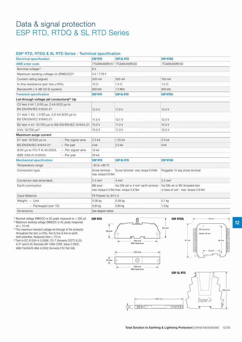
ESP RTD, RTDQ & SL RTD Series - Technical specificationElectrical specification ESP RTD ESP SL RTD ESP RTDQ
ABB order code 7TCA085460R0157 7TCA085400R0232 7TCA085400R0158
Nominal voltage(1) 6 V
Maximum working voltage Uc (RMS/DC)(2) 5 V / 7.79 V
Current rating (signal) 200 mA 500 mA 700 mA
In-line resistance (per line ±10%) 10 Ω 1.0 Ω 1.0 Ω
Bandwidth (-3 dB 50 Ω system) 800 kHz 1.5 MHz 800 kHz
Transient specification ESP RTD ESP SL RTD ESP RTDQ
Let-through voltage (all conductors)(3) Up
C2 test 4 kV 1.2/50 μs, 2 kA 8/20 μs to
BS EN/EN/IEC 61643-21 12.0 V 17.9 V 15.0 V
C1 test 1 kV, 1.2/50 μs, 0.5 kA 8/20 μs to
BS EN/EN/IEC 61643-21 11.5 V 12.1 V 12.5 V
B2 test 4 kV 10/700 μs to BS EN/EN/IEC 61643-21 10.0 V 11.0 V 10.0 V
5 kV, 10/700 μs(4) 10.5 V 11.3 V 10.5 V
Maximum surge current
D1 test 10/350 μs to – Per signal wire 2.5 kA 1.25 kA 2.5 kA
BS EN/EN/IEC 61643-21: – Per pair 5 kA 2.5 kA 5 kA
8/20 μs to ITU-T K.45:2003, – Per signal wire 10 kA
IEEE C62.41.2:2002: – Per pair 20 kA
Mechanical specification ESP RTD ESP SL RTD ESP RTDQ
Temperature range -40 to +80 ºC
Connection type Screw terminal - Screw terminal -max. torque 0.8 Nm Pluggable 12 way screw terminal
max. torque 0.5 Nm
Conductor size (stranded) 2.5 mm2 4 mm2 2.5 mm2
Earth connection M6 stud - Via DIN rail or 4 mm2 earth terminal - Via DIN rail or M5 threaded hole
max. torque 0.5 Nm max. torque 0.8 Nm in base of unit - max. torque 0.6 Nm
Case Material FR Polymer UL-94 V-0
Weight: – Unit 0.08 kg 0.08 kg 0.1 kg
– Packaged (per 10) 0.85 kg 0.85 kg 1.3 kg
Dimensions See diagram below
(1) Nominal voltage (RMS/DC or AC peak) measured at < 200 μA(2) Maximum working voltage (RMS/DC or AC peak) measured at < 10 mA(3) The maximum transient voltage let-through of the protector throughout the test (±10%), line to line & line to earth, both polarities. Response time < 10 ns(4) Test to IEC 61000-4-5:2006, ITU-T (formerly CCITT) K.20, K.21 and K.45,Telcordia GR-1089-CORE, Issue 2:2002, ANSI TIA/EIA/IS-968-A:2002 (formerly FCC Part 68)
7 mm
104.6 mm
106.5 mm
2 S 1 2S E1
95 mm
69 mm
42 mm
M3 clearance
Depth: 18 mm
87 mm
120 mm
38 mm
19 mm
54 mm
105 mmM4 clearance
109 mmM4 clearance
ESP SL RTD
ESP RTD ESP RTDQ
Data & signal protectionESP RTD, RTDQ & SL RTD Series
12/30 Total Solution to Earthing & Lightning Protection | 9AKK106354A3360
12
LPZRTD 0A 3
RTDQ 0A 3
SL RTD 0B 3
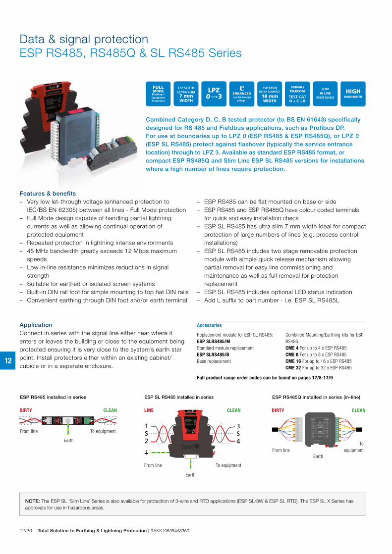
Data & signal protectionESP RS485, RS485Q & SL RS485 Series
NOTE: The ESP SL ‘Slim Line’ Series is also available for protection of 3-wire and RTD applications (ESP SL/3W & ESP SL RTD). The ESP SL X Series has approvals for use in hazardous areas.
Combined Category D, C, B tested protector (to BS EN 61643) specifically designed for RS 485 and Fieldbus applications, such as Profibus DP. For use at boundaries up to LPZ 0 (ESP RS485 & ESP RS485Q), or LPZ 0 (ESP SL RS485) protect against flashover (typically the service entrance location) through to LPZ 3. Available as standard ESP RS485 format, or compact ESP RS485Q and Slim Line ESP SL RS485 versions for installations where a high number of lines require protection.
ApplicationConnect in series with the signal line either near where it enters or leaves the building or close to the equipment being protected ensuring it is very close to the system’s earth star point. Install protectors either within an existing cabinet/cubicle or in a separate enclosure.
Replacement module for ESP SL RS485:ESP SLRS485/M Standard module replacement ESP SLRS485/B Base replacement
Combined Mounting/Earthing kits for ESP RS485:CME 4 For up to 4 x ESP RS485CME 8 For up to 8 x ESP RS485CME 16 For up to 16 x ESP RS485CME 32 For up to 32 x ESP RS485
Full product range order codes can be found on pages 17/8-17/9
ESP
RS48
5ESP RS485
ESP RS485 installed in series
DIRTY CLEAN
From line To equipment
Earth
1S2
3S4
Lightning Barrier
From line
LINE CLEAN
EarthTo equipment
FurseWilford Road,Nottingham,NG2 1EB, UK C
lean
Lin
e
Nominal voltageMax working voltage, UcCurrent ratingIn-line resistance
Max surge currentLet-through voltage, Up
30V36.7V
750mA1.0Ω
20kA63V
ESP SL RS485 installed in series
From line To equipment
LINE CLEAN
Earth
DIRTY CLEAN
ESP RS485Q installed in series (in-line)
From lineTo
equipmentEarth
Features & benefits – Very low let-through voltage (enhanced protection to
IEC/BS EN 62305) between all lines - Full Mode protection – Full Mode design capable of handling partial lightning
currents as well as allowing continual operation of protected equipment
– Repeated protection in lightning intense environments – 45 MHz bandwidth greatly exceeds 12 Mbps maximum
speeds – Low in-line resistance minimizes reductions in signal
strength – Suitable for earthed or isolated screen systems – Built-in DIN rail foot for simple mounting to top hat DIN rails – Convenient earthing through DIN foot and/or earth terminal
– ESP RS485 can be flat mounted on base or side – ESP RS485 and ESP RS485Q have colour coded terminals
for quick and easy installation check – ESP SL RS485 has ultra slim 7 mm width ideal for compact
protection of large numbers of lines (e.g. process control installations)
– ESP SL RS485 includes two stage removable protection module with simple quick release mechanism allowing partial removal for easy line commissioning and maintenance as well as full removal for protection replacement
– ESP SL RS485 includes optional LED status indication – Add L suffix to part number - i.e. ESP SL RS485L
Accessories

Total Solution to Earthing & Lightning Protection | 9AKK106354A3360 12/31
12
ESP RS485, RS485Q & SL RS485 Series - Technical specificationElectrical specification ESP RS485 ESP SL RS485 ESP RS485Q
ABB order code 7TCA085400R0191 7TCA085400R0193 7TCA085400R0192
Nominal voltage(1) 15 V
Maximum working voltage Uc (RMS/DC)(2) 11 V / 16.7 V
Current rating (signal) 300 mA
In-line resistance (per line ±10%) 1 Ω
Bandwidth (-3 dB 50 Ω system) 45 MHz
Transient specification ESP RS485 ESP SL RS485 ESP RS485Q
Let-through voltage (all conductors)(3) Up
C2 test 4 kV 1.2/50 μs, 2 kA 8/20 μs to
BS EN/EN/IEC 61643-21 55.0 V
C1 test 1 kV, 1.2/50 μs, 0.5 kA 8/20 μs to
BS EN/EN/IEC 61643-21 42.0 V
B2 test 4 kV 10/700 μs to BS EN/EN/IEC 61643-21 27.2 V
5 kV, 10/700 μs(4) 28.2 V
Maximum surge current
D1 test 10/350 μs to – Per signal wire 2.5 kA 1.25 kA 2.5 kA
BS EN/EN/IEC 61643-21: – Per pair 5 kA 2.5 kA 5 kA
8/20 μs to ITU-T K.45:2003, – Per signal wire 10 kA
IEEE C62.41.2:2002: – Per pair 20 kA
Mechanical specification ESP RS485 ESP SL RS485 ESP RS485Q
Temperature range -40 to +80 ºC
Connection type Screw terminal - Screw terminal - max. torque 0.8 N Pluggable 12 way screw terminal
max. torque 0.5 Nm
Conductor size (stranded) 2.5 mm2 4 mm2 2.5 mm2
Earth connection M6 stud Via DIN rail or 4 mm2 earth terminal - Via DIN rail or M5 threaded hole in base of unit
max. torque 0.8 Nm
Case Material FR Polymer UL-94 V-0
Weight: – Unit 0.08 kg 0.1 kg
– Packaged (per 10) 0.85 kg 1.3 kg
Dimensions See diagram below
(1) Nominal voltage (RMS/DC or AC peak) measured at < 10 μA(2) Maximum working voltage (RMS/DC or AC peak) measured at < 5 mA(3) The maximum transient voltage let-through of the protector throughout the test (±10%), line to line & line to earth, both polarities. Response time < 10 ns(4) Test to IEC 61000-4-5:2006, ITU-T (formerly CCITT) K.20, K.21 and K.45,Telcordia GR-1089-CORE, Issue 2:2002, ANSI TIA/EIA/IS-968-A:2002 (formerly FCC Part 68)
7 mm
104.6 mm
106.5 mm
2 S 1 2S E1
95 mm
69 mm
42 mm
M3 clearance
Depth: 18 mm
87 mm
120 mm
38 mm
19 mm
54 mm
105 mmM4 clearance
109 mmM4 clearance
ESP SL RS485
ESP RS485 ESP RS485Q
Data & signal protectionESP RS485, RS485Q & SL RS485 Series


![Protection Profile Electronic Signature Verification Module · [TS 101 733] Electronic signature formats, ETSI standard, version 1.5.1, 15 december 2003. Protection Profile Electronic](https://img.dokumen.tips/doc/110x75/6019f03d84d6b076dc0bf9c6/protection-profile-electronic-signature-verification-module-ts-101-733-electronic.jpg)