Embed Size (px)
Citation preview

Toa Electric Co., Ltd.
Model D-5.5, D-5.5E
ELECTRONIC MUSIC MIXEROperating Instruction Manual
KOBE, JAPAN

Contents
General Description . . . . . . . . . . . . . . . . . . . . . . . . . . . . . . . . . . . . . . . . . 2
Features . . . . . . . . . . . . . . . . . . . . . . . . . . . . . . . . . . . . . . . . . . . . . . . . . . 3·4
Front Panel: Names of components & their usage (D-5.5) . . . . . . . 5~9
Rear Panel: Names of components & their usage (D-5.5) . . . . . 10~12
Front Panel: Names of components & their usage (D-5.5E) . . . . . . 13
Rear Panel: Names of components & their usage (D-5.5E) . . . . . . . 14
Block and Level Diagrams . . . . . . . . . . . . . . . . . . . . . . . . . . . . . . . . . 15·16
Specifications (D-5.5, D-5.5E) . . . . . . . . . . . . . . . . . . . . . . . . . . . . . . . 17
Rack Mounting Instructions . . . . . . . . . . . . . . . . . . . . . . . . . . . . . . . . . 18
Procedure for changing internal switch setting . . . . . . . . . . . . . . . . 19
Characteristics Diagam . . . . . . . . . . . . . . . . . . . . . . . . . . . . . . . . . . . . . 20
Appearance . . . . . . . . . . . . . . . . . . . . . . . . . . . . . . . . . . . . . . . . . . . . . . . 20
Precautions
1. Power SupplyThe D-5.5 and the D-5.5E are designed to operate on local AC (50/60Hz) Mains,±10%.
2. XLR Type Audio ConnectorThe connectors are wired as follows.The pin 1 is ground (shield), the pin 2 cold (low, minus), the pin 3 hot (high,plus).
3. Phantom Power SupplyThe phantom power switch on each input channel permits the user to supply 48VDC through the input connectors to a condenser microphone. If phantom power isnot required, the switch must be in the "off" position.
4. Description of components and function on the D-5.5, D-5.5EVarious descriptions are applied, depending on each manufacture. In ourOperating and Instruction Manual explanation of components and functions ismade according to our usage for them.
— 1 —

General Description
The TOA D-5.5 is a 19" rackmount or console configuration, eight-input stereo mixer especially designedfor electronic music and sound. It is expandable to a 32-input mixing system, with group, stereo andmono outputs, and 16 MIDI-THRU jacks, when combined with two D-5.5E 12-input expansion units.The D-5.5 was designed to perform many different applications in broadcast, live sound reinforcement,and recording environments.
The D-5.5 provides four Group outputs, and mixing busses for Aux 1, Aux 2, Effects, Reverb, and Cue.System features include: Sum output selectable pre- or post-fader (St. L + R); two Aux sends, selectablepre-EQ/fader, post-EQ/pre-fader, or post-EQ/fader; Aux returns to Groups 1~4 and Stereo L, R, with pan,level and crossfade controls; an effects patching loop and an internal spring reverb effect are returnableto the 4 groups, stereo L, R, and Aux 1 & 2, with pan, level, and crossfade controls; dual bargraph meters,selectable to Sum/Cue or Stereo L/R; a Headphone output with level control, a Cue buss output withlevel control, and a Cue buss input.
Each input channel features a writing block to identify the source; tape/source selection switch; cueswitch; 60 mm fader; pad and trim controls; two-color LED to indicate signal prescence (green), orclipping (red); channel on/off switch with orange LED indicator; 3-band EQ (high and low shelving-type,and mid peaking-type with frequency sweep control); two Aux sends, selectable pre- or post-EQ; reverbsend to internal spring reverb; effects send; and four group sends via two pan and level controls.
Each of the four Groups features level and crossfade controls for returning Aux and Effects signals to theGroup mixing busses, and a stereo pan for assigning Group signals to the stereo Left and Right mixingbusses. The four groups and Stereo L, R also feature dual-color signal prescence/clip LED indicators; anon/off switch with orange LED; writing block; 60 mm fader; and cue switch.
The D-5.5 rear panel features an RCA tape input, a 1/4" phone jack, and an electronically balanced XLR(with switchable 48-volt phantom powering) for each input channel. Each input also has separate preand post accessory patch points and a direct output. Input channels 7 and 8 are front panel switchable tostereo RIAA inputs, for use with magnetic cartridge turntable.
Group 1~4 output connections are RCA and 1/4" phone jacks; each features separate pre and postaccessory patch points (RCA). Stereo L, R and Sum output connections are individual RCA's, 1/4" phonejacks, and electronically balanced XLR's with ground lift switches. Stereo L, R and Sum outputs alsofeature pre and post accessory patching jacks.
The MIDI jacks are also located on the rear panel. "A" or "B" MIDI inputs are assignable to fourMIDI-THRU outputs (expandable to 16), allowing the use of multiple MIDI instruments without the dataloss or delay that may occur when several instruments are connected serially through their internalMIDI-THRU jacks. Each MIDI-THRU output is provided with a front panel mounted on/off switch.
Also on the rear panel are a Buss-Link connector for connecting D-5.5 Expander units, separate 1/4"phone jacks for stereo L, R Cue buss input and outputs, Aux 1, 2 sends and returns, external Reverb sendand return, and Effects send and return; a push button circuit breaker, chassis ground post, and six-footAC power cord complete the rear panel.
The D-5.5 combines with one D-5.5E for 20-inputs or two D-5.5E's for 32 input channels. Both units canbe mounted in a standard 19" rack, or may be used in a console configuration by removing the rack ears,rotating the rear panel 90 degrees, and attaching the included wooden side panels. The mixers arefinished in an attractive and durable gray enamel, with 3-color control identification markings.
— 2 —

System Features: Each Input Channel Feature:
8 × 4 × 2 × 1 configuration: 8 inputs; 4 sub groups;stereo L & R; mono sum.
Expandable to 32 inputs with two 12 input D-5.5Eexpansion unit.
Rear panel rotates 90 degrees to enable use as consoletype mixer, or as 19" rack mount mixer with theincluded mounting brackets; removable wooden sidepanels.
Selectable 2×4 MIDI Thru function; expandable to2×16.
Stereo RIAA Inputs for turntables with magneticcartridge; selectable from front panel; input channels7 & 8.
2 Aux returns to four groups and Stereo L & R, withlevel and crossfade controls.
Internal spring reverb with dedicated 2-band EQ. Canreturn to four groups, stereo L & R, and Aux 1, 2 withpan, level, and crossfade controls.
Effects patching loop, returnable to four groups,stereo L & R, and Aux 1, 2 with pan, level, andcrossfade controls.
Dual bargraph meters; selectable between Sum/Cueand St L & R.
Sum Output (St L & R); selectable pre or post fader.
2 Aux sends; selectable "pre-EQ and fader," "post-EQ, pre-fader," "post-EQ and fader."
Mono reverb send and mono effects send; both are"post EQ and fader."
Headphones output with level control.
Push button circuit breaker instead of fuse.
Tape/Source Selection switch.
2-color LED indicator for signal presence (green) andclip (red).
Pad and trim controls.
3-band EQ; shelving type for high and low; peakingmid with sweep control.
2 Aux sends; selectable pre or post.
Reverb send to internal spring reverb; post EQ andfader.
Effect send; post EQ and fader.
4 group sends via 2 level and pan controls.
Channel on/off switch with LED indicator (orange).
Writing block.
60 mm fader.
Cue switch.
The D-5.5 is an 8 input, 19" rack mountable mixing console, featuring superioraudio performance, system expandability, and unique "user friendly" design.
Each Group Features:
Level and crossfade controls for returning aux andeffects signals to group busses.
Stereo pan pot to Stereo L & R busses.
2-color LED indicator for signal presence (green) andclip (red).
Channel on/off switch with LED indicator (orange).
Writing block.
60 mm fader.
Cue switch.
Features
— 3 —

Features
Stereo L & R Features: Sum Connections:
2-color LED indicator for signal presence(green) and clip (red).
Channel on/off switch with LED indicator(orange).
Writing block.
60 mm fader.
Cue switch.
REAR PANEL:
Other Connections:
L & R Cue input: 1/4" phone jacks.
L & R Cue Buss output: 1/4" phone jacks.
Aux 1 & 2 sends and Aux 1 & 2 returns: 1/4" phonejacks.
Rev send, and return: 1/4" phone jacks.
Effects send, and return: 1/4" phone jacks.
A and B MIDI Input: DIN plug.
1-4 MIDI Thru: DIN plug.
Buss Link: Multi-pin computer-type connector.
Input Channel Connections:
Separate pre and post accessory patch points: RCA.
Direct Output: RCA.
Source inputs: 1/4" phone jack, and electronicallybalanced XLR with individually switchable 48-voltphantom power.
Tape input: RCA.
RIAA inputs on channels 7 & 8: RCA.
Group 1-4 Connections:
Separate pre and post accessory patch points:RCA.
Direct Output: RCA, 1/4" phone jack.
Stereo L & R Connections:
Separate pre and post accessory patch points: RCA.
Separate pre and post accessory patch points: RCA.
Direct Output: RCA. 1/4" phone jack, and electroni-cally balanced XLR with ground lift switch.
— 4 —
Direct Output: RCA, 1/4" phone jack, and electroni-cally balanced XLR with ground lift switch.
Front Panel (D-5.5)
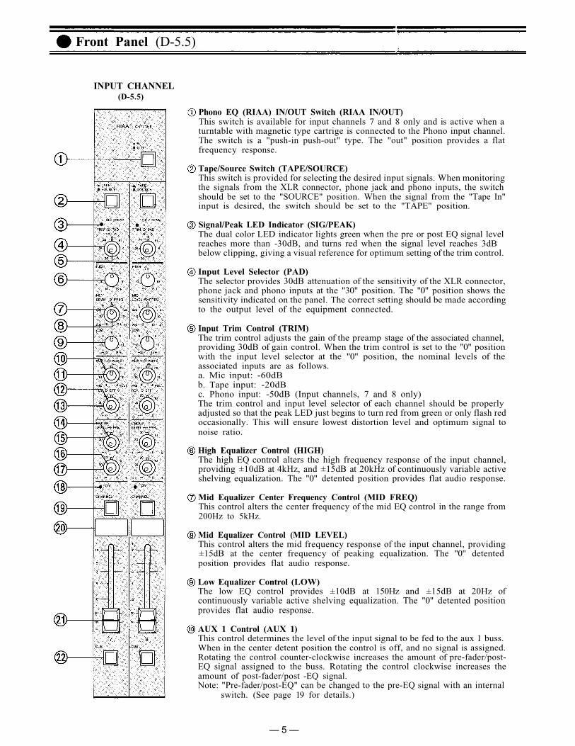
INPUT CHANNEL(D-5.5)
Phono EQ (RIAA) IN/OUT Switch (RIAA IN/OUT)This switch is available for input channels 7 and 8 only and is active when aturntable with magnetic type cartrige is connected to the Phono input channel.The switch is a "push-in push-out" type. The "out" position provides a flatfrequency response.
Tape/Source Switch (TAPE/SOURCE)This switch is provided for selecting the desired input signals. When monitoringthe signals from the XLR connector, phone jack and phono inputs, the switchshould be set to the "SOURCE" position. When the signal from the "Tape In"input is desired, the switch should be set to the "TAPE" position.
Signal/Peak LED Indicator (SIG/PEAK)The dual color LED indicator lights green when the pre or post EQ signal levelreaches more than -30dB, and turns red when the signal level reaches 3dBbelow clipping, giving a visual reference for optimum setting of the trim control.
Input Level Selector (PAD)The selector provides 30dB attenuation of the sensitivity of the XLR connector,phone jack and phono inputs at the "30" position. The "0" position shows thesensitivity indicated on the panel. The correct setting should be made accordingto the output level of the equipment connected.
Input Trim Control (TRIM)The trim control adjusts the gain of the preamp stage of the associated channel,providing 30dB of gain control. When the trim control is set to the "0" positionwith the input level selector at the "0" position, the nominal levels of theassociated inputs are as follows.a. Mic input: -60dBb. Tape input: -20dBc. Phono input: -50dB (Input channels, 7 and 8 only)The trim control and input level selector of each channel should be properlyadjusted so that the peak LED just begins to turn red from green or only flash redoccasionally. This will ensure lowest distortion level and optimum signal tonoise ratio.
High Equalizer Control (HIGH)The high EQ control alters the high frequency response of the input channel,providing ±10dB at 4kHz, and ±15dB at 20kHz of continuously variable activeshelving equalization. The "0" detented position provides flat audio response.
Mid Equalizer Center Frequency Control (MID FREQ)This control alters the center frequency of the mid EQ control in the range from200Hz to 5kHz.
Mid Equalizer Control (MID LEVEL)This control alters the mid frequency response of the input channel, providing±15dB at the center frequency of peaking equalization. The "0" detentedposition provides flat audio response.
Low Equalizer Control (LOW)The low EQ control provides ±10dB at 150Hz and ±15dB at 20Hz ofcontinuously variable active shelving equalization. The "0" detented positionprovides flat audio response.
AUX 1 Control (AUX 1)This control determines the level of the input signal to be fed to the aux 1 buss.When in the center detent position the control is off, and no signal is assigned.Rotating the control counter-clockwise increases the amount of pre-fader/post-EQ signal assigned to the buss. Rotating the control clockwise increases theamount of post-fader/post -EQ signal.Note: "Pre-fader/post-EQ" can be changed to the pre-EQ signal with an internal
switch. (See page 19 for details.)
— 5 —

The D-5.5 incorporates two, switchable MIDI inputsand four MIDI THRU outputs. With the D-5.5E, sixadditional MIDI THRU outputs are available.
MIDI LED Indicator (MIDI IN)This yellow LED indicates the presence of MIDI dataat the MIDI input jack on the rear panel (MIDI IN).
MIDI Input Selector Switch (MIDI IN, A, B)This switch selects either the MIDI input B signal inthe "push" position, or A signal in the "release"position.
CAUTIONWhile the MIDI LED indicator is flashing, do notoperate either the MIDI input selector switch orthe MIDI THRU on/off switch in order to avoidmalfunction of connected MIDI equipment.
MIDI THRU ON/OFF Switch (MIDI THRU ON/OFF)This switch is for "on" or "off" function of each MIDITHRU output. The MIDI THRU is "on" in the "push"position.
(D-5.5E)
MIDI THRU
(D-5.5)
Group Assign Pan Control 1 and 2 (GROUP PAN)This pan control assigns the amount of signaldetermined by the group assign control to the group1 and 2 busses, providing equal output to the group 1and 2 busses at the center position. Rotating the pancontrol clockwise decreases the amount of signal tobe fed to the group 2 buss, keeping the original levelof the signal for the group 1 buss, while rotating thecontrol counter-clockwise decreases the amount ofsignal to be fed to the group 1 buss, keeping theoriginal level of the signal for the group 2 buss.
Cue Switch (CUE)The cue switch is for monitoring the post-EQ,pre-fader signal in each input channel throughheadphone and cue output. The switch is a "push-onpush-off" type. When more than two switches are"on" the signals are combined.
Group Assign Control 3 and 4 (GROUP LEVEL)This control determines the amount of a given inputsignal assigned to the group 3 and 4 via the groupassign control.
Group Assign Pan control 3 and 4 (GROUP PAN)This pan control assigns the amount of signaldetermined by the group assign control to the group3 and 4 busses, providing equal output to the group 3and 4 busses at the detent center position. Rotatingthe pan control counter-clockwise decreases theamount of the signal to be fed to the group 4 buss,keeping the original level of the signal for the group 3buss, while rotating the pan control clockwisedecreases the amount of the signal to be fed to thegroup 3 buss, keeping the original level of the signalfor the group 4 buss.
Channel Switch ON Indicator (CHANNEL ON)The LED indicator lights orange when the channelon/off switch is "on".
Channel ON/OFF Switch (CHANNEL)This pushbutton connects or disconnects the inputsignal to the mixing busses.
Writing BlockThe name of the input equipment or microphonesetting can be written in with an erasable felt pen orgrease pencil.
Input FaderThe fader provides continuously variable adjustmentof the channel's output to the mixing busses. Thenominal level is at the "0" position, with the faderretaining a l0dB margin.
AUX 2 Control (AUX 2)This control determines the level of the input signalto be fed to the aux 2 buss. When in the center detentposition the control is off, and no signal is assigned.Rotating the control counter-clockwise increases theamount of pre-fader/post-EQ signal assigned to thebuss.Rotating the control clockwise increases the amountof post-fader/post-EQ signal.Note: "Pre-fader/post-EQ" can be changed to pre-EQ
signal with an internal switch. (See page 19 fordetails.)
Reverb Control (REV)This control determines the amount of post-fader/post-EQ signal assigned to the reverb buss from agiven input channel, and thus the level of reberb forthat channel.
Effects Control (EFF)This control determines the amount of post-fader/post-EQ signal assigned to the effect buss from agiven input channel, and thus the level of effects forthat channel.
Group Assign Control 1 and 2 (GROUP LEVEL)This control determines the level of input signalassigned to the group buss 1 and 2 via the groupassign pan control.
Front Panel (D-5.5, D-5.5E)
— 6 —

Front Panel (D-5.5)
OUTPUT CHANNEL
Level Control for Return to Group (RET TO GROUP,LEVEL)This control adjusts the level of signal from the AUX1 return and AUX 2 return, or the EFF return andREV return.
Cross-fate Control to Group (RET TO GROUP,X-FADE)With the return signal select switch set to theREV/EFF position, the EFF and REV return signallevels are equally assigned to the group buss. Whenthe control is in its center, detent position. Rotatingthe control counter-clockwise decreases the signallevel of the EFF return, keeping the original level ofthe REV return signal, while rotating the controlclockwise decreases the signal level of the REVreturn, keeping the original level of the EFF returnsignal.With the return signal select switch set to the aux1/aux 2 position, the aux 1 and aux 2 return signallevels are equally assigned to the group buss whenthe control is in its center, detent position. Rotatingthe control counter-clockwise decreases the signallevel of the aux 2 return signal, keeping the originallevel of the aux 1 return signal, while rotating thecontrol clockwise decreases the signal level of theaux 1 return, keeping the original level of the aux 2return signal.
Return Signal Select Switch (REV/EFF, AUX 1 /AUX 2)This switch selects either the REV/EFF return signalsor the AUX 1 / AUX 2 return signals to feed them tothe group buss.
Pan Pot (PAN)The pan pot control assigns the fader output signal ofeach group channel to the stereo L and R mixingbusses. At the detented center position, the pan potroutes the signal equally to the L and R mixingbusses. Panning from one side to the other graduallyassigns the input signal to either the stereo L or Rmixing busses exclusively.
Signal/Peak LED Indicator (SIG/PEAK)The LED indicator lights in green colour when thegroup output signal reaches more than -30dB, andturns to red when the groups signal reaches -3dBbelow clipping, giving a visual reference for adjust-ment of the group fader. (See NOTE 1)
Group Channel ON indicator (CHANNEL ON)The LED indicator lights orange when the groupchannel ON/OFF switch is "on".
Group Channel ON/OFF Switch (CHANNEL)This pushbutton connects or disconnects the signalto the group output and stereo L/R busses.
— 7 —
NOTE 1:Levels should be adjusted so that the LED only
indicates that the channel is being over drivenand the level should be reduced.
flashes red intermittently. A steady red light

Front Panel (D-5.5)
Writing BlockThe name of the source signal can be written in withan erasable felt pen or grease pencil.
Group Fader (GROUP 1 - 4)The 60mm fader provides continuously variableadjustment of the group level to the stereo L and Rbusses, and the group output connectors.
Cue Switch (CUE)The cue switch is for monitoring the pre-fader signalin each group channel through the headphones andcue out. This function is for independent audition ofthe group mixes.
Level Control for Aux 1 Return to Stereo L and R(AUX/RET, LEVEL)This control adjusts the signal level from the AUX 1return and feeds it to the stereo L and R busses viathe pan control.
Pan Pot (PAN)The pan control assigns the signal from the AUX 1return to the stereo L and R busses.
Cue Switch (CUE)The switch permits monitoring the AUX 1 signalprior to the AUX 1 return level control.
Level Control for Aux 2 Return to Stereo L and R(AUX 2 RET, LEVEL)This control adjusts the signal level from the AUX 2return and feeds it to the stereo L and R busses viapan control.
Pan Pot (PAN)The pan control assigns the signal from the AUX 2return to the stereo L and R busses.
Cue Switch (CUE)The switch permits monitoring the AUX 2 signalprior to the AUX 2 return level control.
Level Control for Reverb Return or Built-in Reverbto Stereo L and R (REVERB RET, LEVEL)The control adjusts the signal level from the reverbor the built-in reverb and feeds it to the stereo L andR busses via the pan control.
Pan Pot (PAN)The pan control assigns the signal from the reverbreturn to the stereo L and R busses.
Cue Switch (CUE)The switch permits monitoring the signal prior to thereverb return level control.
Level Control for Effect Return to Stereo L and R(EFF RET, LEVEL)This control adjusts the signal level from the effectsreturn and feeds it to the stereo L and R busses viathe pan control.
Pan Control (PAN)The pan control assigns the signal from the effectsreturn to the stereo L and R busses.
Cue Switch (CUE)The switch permits monitoring the signal prior to theeffect return level control.
Sum Select Switch (SUM SLECT, PRE/POST)This switch selects either the channel pre-fader orpost-fader signals derived from the stereo L and Rbusses, and sends them to the SUM output. Theswitch provides pre-fader signal in the "push"position, and post-fader signal in the "release"position.
Signal/Peak LED Indicator (SIG/PEAK)The LED indicator lights green when the sum outputsignal reaches more than -30dB, and turns to redwhen the signal level reaches -3dB below clipping,giving a visual reference for adjustment of the SUMchannel fader. (See NOTE 1)
Sum Channel ON Indicator and Channel ON/OFFSwitch (CHANNEL ON)The LED indicator lights orange when the channelon/off switch is "on".
Writing Block
Sum Out Fader (SUM)The fader provides continuously variable adjust-ment of the SUM output.
Cue Switch (CUE)The cue switch permits monitoring the pre Sum-fader signal through the headphone and cue output.
Aux 1 / 2 Send Control (AUX SEND, AUX 1 / AUX 2)The aux 1 and aux 2 send controls govern the overalllevel of signal sent to on-stage monitor amplifiers, oran outboard effect device thought the aux 1 and 2send jacks on the rear panel.
Reverb Send Control (REV/EFF SEND, REV)This control governs the overall level of signal sentto the built-in reverb unit or an outboard effectdevice through the reverb send jack on the rearpanel.
Effect Send Control (REV/EFF SEND, EFF)This control governs the overall level of signal sentto an outboard effects device through the Effect Sendjack on the rear panel.
Internal Reverb Equalizer Control (INT REV EQ,HIGH/LOW)These controls alter the frequency response of thebuilt-in reverb circuitry. The high EQ control pro-vides ±10dB at 4kHz, and ±15dB at 20kHz ofcontinuously variable active shelving equalization.
The low EQ control provides ±10dB at 150Hz and±15dB at 20Hz of continuously variable activeshelving equalization. The "0" detented position ofboth controls provide flat audio response.
— 8 —
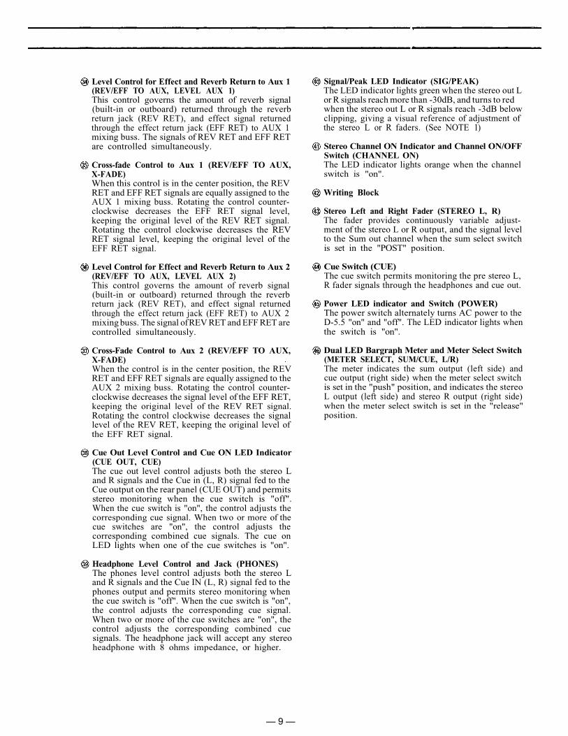
Level Control for Effect and Reverb Return to Aux 1(REV/EFF TO AUX, LEVEL AUX 1)This control governs the amount of reverb signal(built-in or outboard) returned through the reverbreturn jack (REV RET), and effect signal returnedthrough the effect return jack (EFF RET) to AUX 1mixing buss. The signals of REV RET and EFF RETare controlled simultaneously.
Cross-fade Control to Aux 1 (REV/EFF TO AUX,X-FADE)When this control is in the center position, the REVRET and EFF RET signals are equally assigned to theAUX 1 mixing buss. Rotating the control counter-clockwise decreases the EFF RET signal level,keeping the original level of the REV RET signal.Rotating the control clockwise decreases the REVRET signal level, keeping the original level of theEFF RET signal.
Level Control for Effect and Reverb Return to Aux 2(REV/EFF TO AUX, LEVEL AUX 2)This control governs the amount of reverb signal(built-in or outboard) returned through the reverbreturn jack (REV RET), and effect signal returnedthrough the effect return jack (EFF RET) to AUX 2mixing buss. The signal of REV RET and EFF RET arecontrolled simultaneously.
Cross-Fade Control to Aux 2 (REV/EFF TO AUX,X-FADE)When the control is in the center position, the REVRET and EFF RET signals are equally assigned to theAUX 2 mixing buss. Rotating the control counter-clockwise decreases the signal level of the EFF RET,keeping the original level of the REV RET signal.Rotating the control clockwise decreases the signallevel of the REV RET, keeping the original level ofthe EFF RET signal.
Cue Out Level Control and Cue ON LED Indicator(CUE OUT, CUE)The cue out level control adjusts both the stereo Land R signals and the Cue in (L, R) signal fed to theCue output on the rear panel (CUE OUT) and permitsstereo monitoring when the cue switch is "off".When the cue switch is "on", the control adjusts thecorresponding cue signal. When two or more of thecue switches are "on", the control adjusts thecorresponding combined cue signals. The cue onLED lights when one of the cue switches is "on".
Headphone Level Control and Jack (PHONES)The phones level control adjusts both the stereo Land R signals and the Cue IN (L, R) signal fed to thephones output and permits stereo monitoring whenthe cue switch is "off". When the cue switch is "on",the control adjusts the corresponding cue signal.When two or more of the cue switches are "on", thecontrol adjusts the corresponding combined cuesignals. The headphone jack will accept any stereoheadphone with 8 ohms impedance, or higher.
Signal/Peak LED Indicator (SIG/PEAK)The LED indicator lights green when the stereo out Lor R signals reach more than -30dB, and turns to redwhen the stereo out L or R signals reach -3dB belowclipping, giving a visual reference of adjustment ofthe stereo L or R faders. (See NOTE 1)
Stereo Channel ON Indicator and Channel ON/OFFSwitch (CHANNEL ON)The LED indicator lights orange when the channelswitch is "on".
Writing Block
Stereo Left and Right Fader (STEREO L, R)The fader provides continuously variable adjust-ment of the stereo L or R output, and the signal levelto the Sum out channel when the sum select switchis set in the "POST" position.
Cue Switch (CUE)The cue switch permits monitoring the pre stereo L,R fader signals through the headphones and cue out.
Power LED indicator and Switch (POWER)The power switch alternately turns AC power to theD-5.5 "on" and "off". The LED indicator lights whenthe switch is "on".
Dual LED Bargraph Meter and Meter Select Switch(METER SELECT, SUM/CUE, L/R)The meter indicates the sum output (left side) andcue output (right side) when the meter select switchis set in the "push" position, and indicates the stereoL output (left side) and stereo R output (right side)when the meter select switch is set in the "release"position.
— 9 —
RC
A S
tere
o L
& R
Pos
tA
cces
sory
P
atch
P
oint
s(P
OST
IN
/OU
T)
The
se R
CA
pin
jac
ks a
re u
nba-
lanc
ed, w
ith
a no
min
al le
vel o
f —10
dB.
Inpu
t ja
ck i
mpe
danc
e is
10k
ohm
s, a
nd o
utpu
t ja
ck i
mpe
-da
nce
is 1
k oh
ms.
The
Acc
esso
ryja
cks
allo
w s
igna
l pr
oces
sing
and
effe
ct d
evic
es t
o be
ins
erte
d in
toth
e si
gnal
pat
h. T
he r
egul
ar s
ig-
nal
path
is
in
terr
upte
d w
hen
apl
ug i
s in
sert
ed i
nto
the
Acc
es-
sory
In
jack
.
RC
A G
roup
Pre
Acc
esso
ryP
atch
Poi
nts
(PR
E I
N/O
UT
)T
hese
RC
A p
in j
acks
are
unb
a-la
nced
, w
ith
a no
min
al l
evel
of
-10d
B.
Inpu
t ja
ck i
mpe
danc
e is
10k
ohm
s, a
nd o
utpu
t ja
ck i
mpe
-da
nce
is 1
k oh
ms.
The
Acc
esso
ryja
cks
allo
w s
igna
l pr
oces
sing
and
effe
ct d
evic
es t
o be
ins
erte
d in
toth
e si
gnal
pat
h. T
he r
egul
ar s
ig-
nal
path
is
in
terr
upte
d w
hen
apl
ug i
s in
sert
ed i
nto
the
Acc
es-
sory
in
jack
.
RC
A G
roup
Pos
t A
cces
sory
Pat
ch P
oint
s (P
OST
IN
/OU
T)
The
se R
CA
pin
jac
ks a
re u
nba-
lanc
ed,
wit
h a
nom
inal
lev
el o
f—
10d
B. I
nput
jack
impe
danc
e is
10k
ohm
s, a
nd o
utpu
t jac
k im
pe-
danc
e is
1k
ohm
s. T
he A
cces
sory
jack
s al
low
sig
nal p
roce
ssin
g an
def
fect
dev
ices
to
be i
nser
ted
into
the
sign
al p
ath.
The
reg
ular
sig
-na
l pa
th
is
inte
rrup
ted
whe
n a
plug
is
inse
rted
int
o th
e A
cces
-so
ry i
n ja
ck.
AC
Pow
er C
ord
The
pow
er c
ord
is o
f th
e th
ree-
wir
e ty
pe w
ith
prop
er g
roun
ding
faci
litie
s bu
ilt-i
n.
(6ft
.)
Ear
th T
erm
inal
Thi
s te
rmin
al
can
be
used
to
grou
nd o
ther
dev
ices
to t
he D
-5.5
to r
educ
e hu
m a
nd s
hock
haz
ard.
Aux
2 S
end
Jack
(A
UX
2 S
EN
D)
Thi
s 1/
4" p
hone
jac
k ca
n be
use
dei
ther
as
a m
onit
or s
end,
or
inco
njun
ctio
n w
ith
the
Aux
2 R
e-tu
rn j
ack
to c
onne
ct a
n ou
tboa
rdef
fect
s de
vice
(ie
., de
lay
or r
e-ve
rb)
to t
he D
-5.5
. T
he A
ux
2S
end
jack
sho
uld
be c
onne
cted
to
the
inpu
t of
the
eff
ect.
Nom
inal
outp
ut
leve
l is
+
4dB
w
ith
anim
peda
nce
of 1
k oh
ms.
Pus
hbut
ton
Cir
cuit
Bre
aker
(1A
)(P
USH
RE
SET
)T
his
brea
ker
is d
esig
ned
to p
ro-
tect
th
e D
-5.5
in
th
e ev
ent
ofin
tern
al
or
exte
rnal
fa
ult.
Wai
tab
out
two
min
utes
aft
er c
orre
ct-
ing
the
faul
t an
d pu
sh t
he b
utto
nto
re
set
the
syst
em a
nd
rest
ore
prop
er o
pera
tion
.
L &
R C
ue B
uss
Out
put
(CU
E O
UT
L/R
)T
hese
1/4
" ph
one
jack
s pr
ovid
eth
e sa
me
sign
al a
s th
e he
adph
one
outp
ut, a
nd a
re u
sed
for
mon
itor
-in
g th
e si
gnal
s of
the
cue
buss
or
ster
eo L
and
R b
usse
s th
roug
hm
onit
or s
peak
ers.
Thi
s ja
ck h
as a
nom
inal
out
put
leve
l of
+4d
B a
nd a
n im
peda
nce
of 1
k oh
ms.
Aux
1 S
end
Jack
(A
UX
1 S
EN
D)
Thi
s 1/
4" p
hone
jac
k ca
n be
use
dei
ther
as
a m
onit
or s
end,
or
inco
njun
ctio
n w
ith
the
Aux
1 R
e-tu
rn j
ack
to c
onne
ct a
n ou
tboa
rdef
fect
s de
vice
(ie
., de
lay
or r
e-ve
rb)
to t
he D
-5.5
. T
he A
ux
1S
end
jack
sho
uld
be c
onne
cted
to
the
inpu
t of
the
eff
ect.
Nom
inal
outp
ut
leve
l is
+
4dB
w
ith
anim
peda
nce
of 1
k oh
ms.
Sum
Out
put
jack
s(S
UM
OU
TP
UT
)T
he u
nbal
ance
d R
CA
pin
jac
k,1/
4" p
hone
jac
k an
d el
ectr
onic
al-
ly b
alan
ced
XL
R c
onne
ctor
are
wir
ed i
n pa
rall
el.
The
RC
A j
ack
has
a no
min
al
outp
ut
leve
l of
-l0
dB
an
d a
n i
mp
edan
ce o
f 1k
ohm
s, a
nd t
he 1
/4"
phon
e ja
ckha
s a
nom
inal
ou
tput
le
vel
of+
4dB
and
an
impe
danc
e of
1k
ohm
s. T
he X
LR
con
nect
or h
as a
nom
inal
ou
tput
le
vel
of
+4d
Ban
d an
im
peda
nce
of 1
k oh
ms.
All
ja
cks
may
be
us
ed
sim
ul-
tane
ousl
y.
Gro
und
Lif
t Sw
itch
(G
ND
)T
hese
sw
itch
are
ass
igne
d to
the
XL
R S
um O
utpu
t an
d St
ereo
L &
R
conn
ecto
rs,
and
are
used
to
avoi
d gr
ound
loo
ps a
nd i
nduc
edhu
m t
hat
som
etim
es o
ccur
whe
nco
nnec
ting
the
D-5
.5's
XL
R S
umO
utpu
t or
Ste
reo
L &
R O
utpu
tw
ith
othe
r eq
uipm
ent.
Sli
ding
the
Gro
und
Lif
t Sw
itch
from
the
NO
RM
AL
pos
itio
n to
the
LIF
Tpo
siti
on b
reak
s th
e gr
ound
con
-ne
ctio
n an
d m
ay r
educ
e hu
m a
ndno
ise.
For
mos
t ap
plic
atio
ns t
hew
itch
sho
uld
be l
eft
in t
he N
OR
-M
AL
pos
itio
n.
Eff
ect
Ret
urn
Jack
(E
FF
RE
T)
Thi
s 1/
4" p
hone
jac
k is
use
d in
conj
unct
ion
wit
h th
e E
ffec
t S
end
jack
to
co
nnec
t an
ou
tboa
rdef
fect
s de
vice
(i
e.,
dela
y or
re-
verb
) to
th
e D
-5.5
. T
he
Eff
ect
Ret
urn
jack
sho
uld
be c
onne
cted
to
the
outp
ut
of
the
effe
ct.
Nom
inal
inp
ut l
evel
is
— 2
0dB
wit
h an
im
peda
nce
of 1
0k o
hms.
Rev
erb
Ret
urn
Jack
(R
EV
RE
T)
Thi
s 1/
4" p
hone
jac
k is
use
d in
conj
unct
ion
wit
h th
e R
ever
bse
nd j
ack
to c
onne
ct a
n ou
tboa
rdef
fect
s de
vice
(ie
., de
lay
or r
e-ve
rb)
to
the
D-5
.5.
The
E
ffec
tR
etur
n ja
ck s
houl
d be
con
nect
edto
the
out
put
of th
e ef
fect
dev
ice.
Nom
inal
in
put
leve
l is
-2
0dB
wit
h an
im
peda
nce
of 1
0k o
hms.
Whe
n a
plug
is
inse
rted
int
o th
isja
ck,
the
buil
t-in
rev
erb
circ
uitr
yis
aut
omat
ical
ly c
ut o
ff.
CA
UT
ION
- T
he g
roun
d pi
n on
the
AC
plu
g sh
ould
not
be
re-
mov
ed u
nder
any
cir
cum
stan
ces.
If t
he D
-5.5
mus
t be
use
d on
an
AC
cir
cuit
wit
h no
gro
und
or a
ndop
en
grou
nd,
then
a
suit
able
grou
ndin
g ad
apte
r sh
ould
be
used
an
d it
s gr
ound
te
rmin
alsh
ould
be
secu
rely
att
ache
d to
ago
od e
arth
con
nect
ion.
Fai
lure
todo
so
w
ill
resu
lt
in
incr
ease
dno
ise
and
shoc
k ha
zard
.
Aux
1 R
etur
n Ja
ck (
AU
X 1
RE
T)
Thi
s 1/
4" p
hone
jac
k ca
n be
use
din
con
junc
tion
wit
h th
e A
ux
1Se
nd j
ack
to c
onne
ct a
n ou
tboa
rdef
fect
s de
vice
(ie
., de
lay
or r
e-ve
rb)
to
the
D-5
.5.
The
A
ux
1R
etur
n ja
ck s
houl
d be
con
nect
edto
th
e ou
tput
of
th
e ef
fect
.N
omin
al i
nput
lev
el i
s —
20d
Bw
ith
an i
mpe
danc
e of
10k
ohm
s.
Aux
2 R
etur
n Ja
ck (
AU
X 2
RE
T)
Thi
s 1/
4" p
hone
jac
k ca
n be
use
din
con
junc
tion
wit
h th
e A
ux 2
Send
jac
k to
con
nect
an
outb
oard
effe
cts
devi
ce (
ie.,
dela
y or
re-
verb
) to
th
e D
-5.5
. T
he
Aux
2
Ret
urn
jack
sho
uld
be c
onne
cted
to
the
outp
ut
of
the
effe
ct.
Nom
inal
in
put
leve
l is
-2
0dB
wit
h an
im
peda
nce
of 1
0k o
hms.
Eff
ect
Send
Jac
k (E
FF
SE
ND
)T
his
1/4"
pho
ne j
ack
is u
sed
inco
njun
ctio
n w
ith
the
Eff
ect
Re-
turn
jac
k to
con
nect
an
outb
oard
effe
cts
devi
ce (
ie.,
dela
y or
re-
verb
) to
th
e D
-5.5
. T
he
Eff
ect
Sen
d ja
ck s
houl
d be
con
nect
ed to
the
inpu
t of
the
eff
ect.
Nom
inal
outp
ut
leve
l is
+
4dB
w
ith
anim
peda
nce
of I
k oh
ms.
Rev
erb
Sen
d J
ack
(R
EV
SE
ND
)T
his
1/4"
pho
ne j
ack
is u
sed
inco
njun
ctio
n w
ith
the
Rev
erb
Re-
turn
jac
k to
con
nect
an
outb
oard
effe
cts
devi
ce (
ie.,
dela
y or
re-
verb
) to
the
D-5
.5.
The
Rev
erb
Sen
d ja
ck s
houl
d be
con
nect
ed to
the
inpu
t of
the
eff
ect.
Nom
inal
outp
ut
leve
l is
+
4dB
w
ith
anim
peda
nce
of 1
k oh
ms.
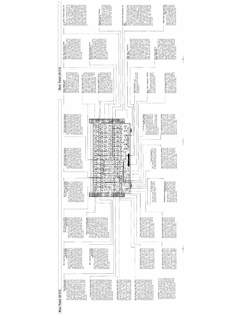
Rea
r P
anel
(D
-5.5
)R
CA
Sum
Pos
t A
cces
sory
Pat
ch P
oint
s(P
OST
IN
/OU
T)
The
se R
CA
pin
jac
ks a
re u
nba-
lanc
ed,
wit
h a
nom
inal
lev
el o
f—
l0dB
. In
put
jack
im
peda
nce
is10
k oh
ms,
and
out
put
jack
im
pe-
danc
e is
1k
ohm
s. T
he A
cces
sory
jack
s al
low
sig
nal
proc
essi
ng a
ndef
fect
dev
ices
to
be i
nser
ted
into
the
sign
al p
ath,
the
reg
ular
sig
nal
path
is
inte
rrup
ted
whe
n a
plug
is i
nser
ted
into
the
Acc
esso
ry i
nja
ck.
RC
A S
um P
re A
cces
sory
Pat
ch P
oint
(PR
E I
N/O
UT
)T
hese
RC
A p
in j
acks
are
unb
a-la
nced
, w
ith
a no
min
al l
evel
of
— l0
dB.
Inpu
t jac
k im
peda
nce
is10
k oh
ms,
and
out
put j
ack
impe
-da
nce
is 1
k oh
ms.
The
Acc
esso
ryja
cks
allo
w s
igna
l pr
oces
sing
and
effe
ct d
evic
es t
o be
ins
erte
d in
toth
e si
gnal
pat
h. T
he r
egul
ar s
ig-
nal
path
is
in
terr
upte
d w
hen
apl
ug i
s in
sert
ed i
nto
the
Acc
es-
sory
in
jack
.
Ster
eo L
& R
out
put
jack
s(S
T L
& S
T R
OU
TPU
T)
The
unb
alan
ced
RC
A p
in j
acks
,1/
4" p
hone
jac
ks
and
elec
tron
i-ca
lly
bala
nced
X
LR
co
nnec
tors
are
wir
ed i
n pa
rall
el.
The
RC
Aja
ck h
as a
nom
inal
out
put l
evel
of
— l0
dB a
nd a
n im
peda
nce
of 1
koh
ms,
an
d th
e 1/
4" p
hone
jac
kha
s a
nom
inal
ou
tput
le
vel
of+
4dB
an
d an
im
peda
nce
of 1
koh
ms.
The
XL
R c
onne
ctor
s ha
vea
nom
inal
out
put
leve
l of
+4d
Ban
d an
im
peda
nce
of 1
k oh
ms.
All
ja
cks
may
be
us
ed
sim
ul-
tane
ousl
y.RC
A S
tere
o L
& R
Pre
Acc
esso
ry P
atch
Poi
nts
(PR
E I
N/O
UT
)T
hese
RC
A p
in j
acks
are
unb
a-la
nced
, w
ith
a no
min
al l
evel
of
— l0
dB.
Inpu
t jac
k im
peda
nce
is10
k oh
ms,
and
out
put j
ack
impe
-da
nce
is 1
k oh
ms.
The
Acc
esso
ryja
cks
allo
w s
igna
l pro
cess
ing
and
effe
ct d
evic
es t
o be
ins
erte
d in
toth
e si
gnal
pat
h. T
he r
egul
ar s
ig-
nal
path
is
inte
rrup
ted
whe
n a
plug
is
inse
rted
int
o th
e A
cces
-so
ry i
n ja
ck.
Rea
r P
anel
(D
-5.5
)G
roup
Out
put
jack
s(G
RO
UP
OU
TPU
T)
The
unb
alan
ced
RC
A p
in j
acks
and
1/4"
pho
ne j
acks
are
wir
ed i
npa
rall
el.
The
R
CA
ja
ck
has
ano
min
al o
utpu
t le
vel
of —
10d
Ban
d an
im
peda
nce
of 1
k oh
ms,
whi
le t
he 1
/4"
jack
has
a n
omin
alou
tput
le
vel
of
+4d
B
and
anim
peda
nce
of 1
k oh
ms.
The
jack
sm
ay b
e us
ed s
imul
tane
ousl
y.
RC
A T
ape
Inpu
t (T
AP
E I
N)
The
se R
CA
pin
jac
ks a
re u
nba-
lanc
ed,
wit
h a
nom
inal
lev
el o
f-2
0dB
an
d im
peda
nce
of 1
0koh
ms,
and
acc
ept
inpu
t so
urce
sfr
om
-20d
B
to
+ 1
0dB
. P
rope
rad
just
men
t of
bot
h tr
im c
ontr
ol(T
RIM
) an
d in
put
fade
r en
sure
opti
mum
si
gnal
-to-
nois
e ra
tio
and
min
imum
dis
tort
ion.
Dir
ect
Out
put
(DIR
EC
T O
UT
)T
he D
irec
t O
utpu
t on
eac
h ch
an-
nel
util
izes
an
unba
lanc
ed R
CA
pin
jack
wit
h an
im
peda
nce
of 1
koh
ms
and
a le
vel
of -
10dB
. T
heD
irec
t O
utpu
t is
po
st-E
Q/p
ost-
fade
r, a
nd i
s us
eful
for
rec
ordi
ngan
d fo
r se
ndin
g in
divi
dual
in
-st
rum
ents
to
a m
ain
PA
mix
erth
roug
h di
rect
box
es.
RC
A P
ost
Acc
esso
ry P
atch
Poi
nts
(PO
ST I
N/O
UT
)T
hese
RC
A p
in j
acks
are
unb
a-la
nced
, w
ith
a no
min
al l
evel
of
-10d
B.
Inpu
t ja
ck i
mpe
danc
e is
10k
ohm
s, a
na!
outp
ut ja
ck im
pe-
danc
e is
1k
ohm
s. T
he A
cces
sory
jack
s al
low
sig
nal
proc
essi
ng a
ndef
fect
dev
ices
to
be i
nser
ted
into
the
sign
al p
ath.
The
reg
ular
sig
-na
l pa
th i
s in
terr
upte
d w
hen
apl
ug i
s in
sert
ed i
nto
the
Acc
es-
sory
In
jack
.
RC
A P
re A
cces
sory
Pat
chP
oint
s (P
RE
IN/O
UT
)T
hese
RC
A p
in j
acks
are
unb
a-la
nced
, w
ith
a no
min
al l
evel
of
-10d
B.
Inpu
t ja
ck i
mpe
danc
e is
10k
ohm
s, a
nd o
utpu
t ja
ck i
mpe
-da
nce
is 1
k oh
ms.
The
Acc
esso
ryja
cks
allo
w s
igna
l pr
oces
sing
and
effe
ct d
evic
es t
o be
ins
erte
d in
toth
e si
gnal
pat
h. T
he r
egul
ar s
ig-
nal
path
is
in
terr
upte
d w
hen
apl
ug i
s in
sert
ed i
nto
the
Acc
es-
sory
in
jack
.
1/4"
ph
one
Cha
nnel
Inp
ut
(IN
-P
UT
)T
his
jack
is a
sta
ndar
d 1/
4" p
hone
jack
, w
ith
a no
min
al
leve
l of
-40d
B
and
an
impe
danc
e of
100k
oh
ms,
an
d ac
cept
s in
put
sour
ces
from
-40
dB t
o +
20dB
.P
rope
r ad
just
men
t of t
he p
ad a
ndti
rm c
ontr
ol (
PA
D/T
RIM
) an
d in
-pu
t fad
er e
nsur
e op
tim
um s
igna
l-to
-noi
se r
atio
and
min
imum
dis
-to
rtio
n. W
hen
a pl
ug i
s in
sert
edin
to t
he 1
/4"
inpu
t ja
ck,
the
cor-
resp
ondi
ng
XL
R
mic
in
put
orph
ono
inpu
t is
au
tom
atic
ally
swit
ched
out
of t
he i
nput
cir
cuit
-ry
-
Pha
ntom
Pow
er S
wit
ches
(PH
AN
TO
M1~
8)T
he
phan
tom
pow
er
swit
ch
onea
ch i
nput
cha
nnel
per
mit
s th
eus
er t
o su
pply
48V
DC
thr
ough
the
inpu
t co
nnec
tors
to
a co
nde-
nser
m
icro
phon
e.
If
phan
tom
pow
er is
not
req
uire
d, t
he s
wit
chm
ust
be i
n th
e "o
ff"
posi
tion
.
Ear
th T
erm
inal
The
se
may
be
used
to
pr
ovid
egr
ound
con
nect
ion
for
tape
dec
ksor
tur
ntab
les.
MID
I T
hru
Con
nect
ors
(MID
I T
HR
U)
The
MID
I si
gnal
fro
m t
he M
IDI
Inpu
t con
nect
or (M
IDI I
N, A
/B) i
ssp
lit
and
sent
un
alte
red
to
the
four
MID
I Thr
u co
nnec
tors
on
the
D-5
.5,
and
to s
ix m
ore
MID
I T
hru
conn
ecto
rs o
n th
e D
-5.5
E, i
f use
d.E
ach
of t
he M
IDI
Thr
u ja
cks
can
be c
onne
cted
to a
dif
fere
nt s
ynth
-es
izer
's M
IDI
Inpu
t ja
ck,
allo
w-
ing
one
MID
I ke
yboa
rd
or
se-
quen
cer
to
cont
rol
up
to
four
othe
r M
IDI
synt
hs.
(ten
w
hen
usin
g th
e D
-5.5
E
and
sixt
een
whe
n us
ing
the
two
D-5
.5E
's.)
Bal
ance
d X
LR
Mic
roph
one
In-
put
(MIC
)T
he X
LR
-typ
e m
icro
phon
e in
put
conn
ecto
rs a
re e
lect
roni
call
y ba
-la
nced
wit
h a
nom
inal
lev
el
of—
60dB
and
an
inpu
t im
peda
nce
of 1
k oh
ms,
and
wil
l ac
cept
sig
-na
ls f
rom
-60
dB t
o 0d
B.
Pha
n-to
m p
ower
ing
is p
rovi
ded
for
use
wit
h co
nden
ser-
type
m
ic-
roph
ones
(se
e P
HA
NT
OM
), a
ndon
ce a
gain
the
prop
er a
djus
tmen
tof
Pad
and
Tri
m c
ontr
ol (
PA
D/
RT
IM)
and
Inpu
t F
ader
wil
l in
-su
re
opti
mum
si
gnal
-to-
nois
era
tio
and
min
imum
di
stor
tion
.T
he m
ic i
nput
is
auto
mat
ical
lydi
scon
nect
ed
whe
n ei
ther
th
eco
rres
pond
ing
the
1/4"
ph
one
jack
is
used
.
MID
I In
put
DIN
Con
nect
ors
(MID
I IN
, A
/B)
The
se c
onne
ctor
s w
ill
acce
pt t
heM
IDI
outp
ut o
f an
y sy
nthe
size
r,se
quen
cer,
or
othe
r M
IDI
devi
ce.
Use
of
non-
MID
I-st
anda
rd D
INca
bles
, or
of
cabl
es l
onge
r th
an5m
(16
'5")
may
res
ult
in i
mpr
op-
er o
pera
tion
and
dat
a lo
ss.
RC
A P
hono
(R
IAA
)In
puts
(P
HO
NO
)T
hese
R
CA
pi
n ja
cks
have
a
nom
inal
lev
el o
f —
50d
B a
nd a
nim
peda
nce
of
50k
ohm
s,
and
acce
pt i
nput
sou
rces
fro
m -
50dB
to +
10dB
. P
rope
r ad
just
men
t of
the
pad
and
trim
con
trol
(P
AD
/T
RIM
) an
d in
put
fade
r en
sure
opti
mum
si
gnal
-to-
nois
e ra
tio
and
min
imum
dis
tort
ion.
Whe
nus
ing
a tu
rnta
ble
wit
h m
agne
tic
cart
ridg
e,
plac
e th
e ph
ono
EQ
IN/O
UT
sw
itch
on
the
fron
t pan
elto
the
"i
n"
posi
tion
.
Bus
s L
ink
C
onne
ctor
(B
US
SL
INK
)T
his
conn
ecto
r is
use
d to
lin
k th
eD
-5.5
wit
h th
e D
-5.5
E. E
xpan
der.
A
six-
foot
co
nnec
ting
co
rd
isin
clud
ed w
ith
the
D-5
.5E
.
L &
R C
ue In
put (
CU
E I
N L
/R)
The
se
1/4"
ph
one
jack
s al
low
acce
ss
to
the
ster
eo
cue
buss
.T
his
feat
ure
is e
spec
iall
y co
nve-
nien
t du
ring
rec
ordi
ng
appl
ica-
tion
s. T
hese
jack
s ha
ve a
nom
inal
inpu
t le
vel
of
-10d
B
wit
h an
impe
danc
e of
10k
ohm
s.
— 1
1 —
— 1
0 —
—
12
—
Front Panel (D-5.5E)
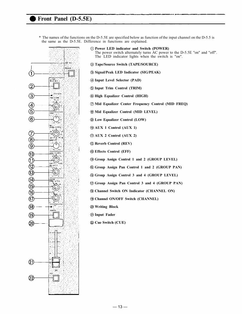
* The names of the functions on the D-5.5E are specified below as function of the input channel on the D-5.5 isthe same as the D-5.5E. Difference in functions are explained.
Power LED indicator and Switch (POWER)The power switch alternately turns AC power to the D-5.5E "on" and "off".The LED indicator lights when the switch is "on".
Tape/Source Switch (TAPE/SOURCE)
Signal/Peak LED Indicator (SIG/PEAK)
Input Level Selector (PAD)
Input Trim Control (TRIM)
High Equalizer Control (HIGH)
Mid Equalizer Center Frequency Control (MID FREQ)
Mid Equalizer Control (MID LEVEL)
Low Equalizer Control (LOW)
AUX 1 Control (AUX 1)
AUX 2 Control (AUX 2)
Reverb Control (REV)
Effects Control (EFF)
Group Assign Control 1 and 2 (GROUP LEVEL)
Group Assign Pan Control 1 and 2 (GROUP PAN)
Group Assign Control 3 and 4 (GROUP LEVEL)
Group Assign Pan Control 3 and 4 (GROUP PAN)
Channel Switch ON Indicator (CHANNEL ON)
Channel ON/OFF Switch (CHANNEL)
Writing Block
Input Fader
Cue Switch (CUE)
— 13 —

AC Power Cord(6 ft.)
Pushbutton Circuit Breaker(1A)
(PUSH RESET)This breaker is designed toprotect the D-5.5E in theevent of internal or externalfault. Wait about two mi-nutes after correcting thefault and push the button toreset the system and restoreproper operation.
MIDI Thru Connectors(MIDI THRU)The MIDI signal from theMIDI input connector (MIDIIN) is split and sent un-altered to the four MIDI Thruconnectors on the D-5.5, andto six more MIDI Thru con-nectors on the D-5.5E, ifused. Each of the MIDI Thrujacks can be connected to adifferent synthesizer's MIDIinput jack, allowing oneMIDI keyboard or sequencerto control up to four otherMIDI synths. (ten when usingthe D-5.5E and sixteen whenusing the two D-5.5E's.)
Earth Terminal
Balanced XLR MicrophoneInput (MIC)
Phantom Power Switches(PHANTOM 9~20)
1/4" Phone ChannelInput (INPUT)
RCA Pre AccessoryPatch Points(PRE IN/OUT)
RCA Post AccessoryPatch Points(POST IN/OUT)
Direct Output(DIRECT OUT)
RCA Tape Input(TAPE IN)
* The names of the functions on the D-5.5E are specified below as connection of theinput channel on the D-5.5 is the same as the D-5.5E. Difference in functions andconnection are explained.
Rear Panel (D-5.5E)
Buss Link Connector(BUSS LINK OUT)
This connector is used tolink the D-5.5E Expanderwith the D-5.5. A six-footconnecting cord is includedwith the D-5.5E.
Buss Link Connector(BUSS LINK IN)
This connector is used tolink the D-5.5E Expanderwith another D-5.5E Expan-der.
— 14 —

Block Diagrams
D-5.5 BLOCK DIAGRAM
D-5.5E BLOCK DIAGRAM
— 15 —

D-5.5 LEVEL DIAGRAM
Level Diagrams
D-5.5E LEVEL DIAGRAM
— 16 —

D-5.5E ONLYStereo phone jack is wired : Tip=Left, Ring=Right and Sleave=Common.All XLR type connectors are electronically balanced.The XLR type connectors are wired as follows Pin No.l-Ground, Pin No.2-Cold (Low), Pin No.3-Hot (High)
OUTPUT SPECIFICATIONS (D-5.5, D-5.5E)
D-5.5E ONLYAll XLR type connectors are electronically balanced.The XLR type connectors are wired as follows. Pin No.1-Ground, Pin No.2-Cold (Low), Pin No.3-Hot (High)
0dB is referenced to 0.775V RMS
Connector
¼" PHONE JACKRCA PIN JACKXLR-3-32 TYPE¼" PHONE JACKRCA PIN JACK
¼" PHONE JACK
RCA PIN JACK
RCA PIN JACK
¼" PHONE JACK¼" STEREO
PHONE JACK
Output Level
Nominal MAX. Before ClipFor Use With NominalActual Source ImpedanceOutput
GROUP 1~4
STEREO L & R SUM
AUX1 SEND, AUX2 SENDREV SEND, EFF SENDACCESSORY OUTPRE/POST (INPUT, GROUP,STEREO, SUM)DIRECT OUT 1~8<9~20>CUE OUT L & R
PHONES
Input
MIC 1~8<9~20>
INPUT 1~8<9~20>
PAD
0
30
0
30
TAPE 1~8<9~20>
PHONO (RIAA) 7 & 8
ACCESSORY IN PRE/POST(INPUT, GROUP, STEREO,SUM)
AUX1 RET, AUX2 RETREV RET, EFF RET
CUE IN L & R
Actual LoadImpedance
For UseWith Nominal
INPUT SPECIFICATIONS (D-5.5, D-5.5E)Input Level (Trim "0" to Trim "-30")
Nominal-60dB (0.78mV)
to -30dB (25mV)-30dB (25mV)
to 0dB (780mV)-40dB (7.8mV)
to -10dB (250m V)-10dB (250mV)
to + 20dB (7.8V)-20dB (78mV)
to + 10dB (2.5V)-50dB (2.5mV)
to -20dB (78mV) at 1kHz
-10dB (250mV)
-20dB (78mV)
-10dB (250mV)
MAX. Before Clip-40dB (7.8mV)
to -10dB (250mV)-10dB (250mV)
to +20dB (7.8V)-20dB (78mV)
to +10dB (2.5V)+10dB (2.5V)
to +40dB (78V)0dB (780mV)
to +30dB (25V)-30dB (25mV)
to 0dB (780mV) at 1kHz+ 10dB (2.5V)EXCEPT GROUP, STERO,SUM. ACCESSORY IN POST+6dB (1.6V)
+10dB (2.5V)
+24dB (12V)
Connector
XLR-3-31 TYPE
¼" PHONE JACK
RCA PIN JACK
RCA PIN JACK
RCA PIN JACK
¼" PHONE JACK
¼" PHONE JACK
0dB is referenced to 0.775V RMS
Accessory (D-5.5E ONLY)BUSS LINK CABLE 6ft. 1
* 0dB is referenced to 0.775V RMSSpecifications are subject to change without notice.
WeightD-5.5, D-5.5E22kg (48.5lbs)
Dimensions (W×D×H)
Power ConsumptionD-5.5 41WD-5.5E 39W
Meter ("0" = Nominal level of STEREO, SUM OUT and CUE bus)pair of 12 segment bargraph LED meter for STEREO L, R or SUM,CUE
Phantom Power48V DC is applied to MIC Input for powering condenser mic-rophones
Sig./Peak Indicator
EqualizationLOW ±15dB 20Hz ShelvingMID ±15dB 200Hz to 5kHz Variable PeakingHIGH ±15dB 20kHz Shelving
Sig. (Green) LED turn on at -30dB below nominal levelPeak (Red) LED turn over from Sig. (Green) at -3dB below clipping
Maximum Voltage GainMIC IN to SUM OUTMIC IN to STEREO OUT
MIC IN to GROUP OUTINPUT to GROUP OUTINPUT to AUX½, REV, EFF SENDAUX½, REV, EFF RET to GROUP OUT
All Fader minimumMaster (GROUP, STEREO or SUM) FaderNominal, D-5.5 onlyMaster (GROUP) Fader Nominal, D-5.5E con-nectionMaster (GROUP) and One Input FaderNominal
Equivalent Input Noise (MIC IN)Equivalent Input Noise IHF-A weighted (MIC IN)
Hum and Noise (20Hz to 20kHz)
Total Harmonic DistortionLess thanLess than
(MIC IN)(INPUT)
GENERAL SPECIFICATIONSFrequency Response
+0dB, -0.5dB 50Hz to 20kHz+0dB, -3.0dB 20Hz to 50kHz
Specifications (D-5.5, D-5.5E)
MICROPHONES
or LOWERIMP. LINES
or LOWERIMP. LINES
or LOWERIMP. LINES
or LOWERIMP. LINES
or LOWERIMP. LINES
Lines
Lines
Lines
Lines
Lines
Lines
or higher
+4dB (1 .2V)-10dB (250mV)+4dB (1.2V)+4dB (1.2V)-10dB (250mV)
+4dB (1.2V)
+ 10dB (250mV)
-10dB (250mV)
+4dB (1.2V)
+20dB (7.8V)+6dB (1.6V)+20dB (7.8V)+ 20dB (7.8V)
+ 6dB (1.6V)
+20dB (7.8V)
+ 20dB (7.8V)
+ 10dB (2.5V)
+ 20dB (7.8V)-6dB (390mV)/8+ 20dB (7.8V)/OPEN
104dB94dB
84dB64dB54dB34dB
-125dB*-127dB*
-100dB*-70dB*
-65dB*
-61dB*
0.3%0.1%
+4dB*+4dB*
1kHz1kHz
— 17 —

Rack Mounting Instructions
The D-5.5 and D-5.5E are designed for either console or rack-mount use, using a pair ofbrackets (included). The following procedure should be observed for the rack-mount use.
1. Remove both side panelsand armrest unscrewingand removing 6 screws.
2. Mount the brackets on bothsides of the chassis, using thescrews removed from theside panels.
3. The rear panel and blankpanel should be inter-changed to allow for easyconnection when the D-5.5and D - 5 . 5 E are r ackmounted.
a. Remove the rear panel corner frame and blank panelb. Put the rear panel in the original position of the blank panel.c. Put the corner frame back in place.d. Put the blank panel in the original position of the rear panel.
WARNING
The D-5.5 and D-5.5E contain voltage levels that may be hazardous to human life. Alwaysdisconnect the power cord from wall outlet prior to removing either unit's outer case.
— 18 —
Procedure for Changing Internal Switch Setting
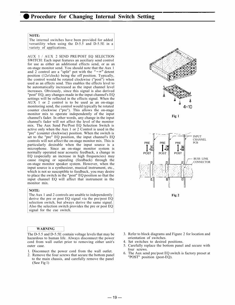
NOTE:The internal switches have been provided for addedversatility when using the D-5.5 and D-5.5E in avariety of applications.
AUX 1 / AUX 2 SEND PRE/POST EQ SELECTIONSWITCH: Each input features an auxiliary send controlfor use as either an additional effects send, or as anon-stage monitor send. You should note that the Aux 1and 2 control are a "split" pot with the detentposition (12o'clock) being the off position. Typically,the control would be rotated clockwise ("post") whenused as an effects send. This enables the effects level tobe automatically increased as the input channel levelincreases. Obviously, since this signal is also derived"post" EQ, any changes made in the input channel's EQsettings will be reflected in the effects signal. When theAUX 1 or 2 control is to be used as an on-stagemonitoring send, the control would typically be rotatedcounter clockwise ("pre"). This allows the on-stagemonitor mix to operate independently of the inputchannel's fader. In other words, any change in the inputchannel's fader will not affect the level of the monitormix. The Aux Send Pre/Post EQ Selection Switch isactive only when the Aux 1 or 2 Control is used in the"pre" (counter clockwise) position. When the switch isset to the "pre" EQ position, the input channel's EQcontrols will not affect the on-stage monitor mix. This isparticularly desirable when the input source is amicrophone. Since an on-stage monitor system isnormally operated near acoustic feedback, a change inEQ (especially an increase in high frequencies) maycause ringing or squealing (feedback) through theon-stage monitor speaker system. However, when theinput source is a synthesizer, musical instrument, etc.,which is not so susceptible to feedback, you may desireto place the switch in the "post" EQ position so that theinput channel EQ will affect that instrument in themonitor mix.
NOTE:The Aux 1 and 2 controls are unable to independentlyderive the pre or post EQ signal via the pre/post EQselection switch, but always derive the same signal.Also the selection switch provides the pre or post EQsignal for the cue switch.
WARNING
The D-5.5 and D-5.5E contain voltage levels that may behazardous to human life. Always disconnect the powercord from wall outlet prior to removing either unit'souter case.
1. Disconnect the power cord from the wall outlet.2. Remove the four screws that secure the bottom panel
to the main chassis, and carefully remove the panel(See Fig 1)
Fig l
INPUTCHANNELPCBPRE
POSTPOST
PREPRE
POST
BUSS LINKCONNECTOR
Fig 2
3. Refer to block diagrams and Figure 2 for location andorientation of switches.
4. Set switches to desired positions.5. Carefully replace the bottom panel and secure with
four screws.6. The Aux send pre/post EQ switch is factory preset at
"POST" position (post-EQ).
— 19 —

* Dimensions with brackets
D-5.5E
* Dimensions with brackets
Appearance
D-5.5
FREQUENCY RESPONSEINPUT EQ CHARACTERISTICS
Characteristics Diagrams
FREQUENCY FREQUENCY
LEV
EL
LEV
EL
— 20 —

Toa Electric Co., Ltd.KOBE, JAPAN
Printed in Japan133-02-748-80

![world.toagroup.com...the natural world and is very effective in creating a country style. TOA Prairie TOA TOA TOA 851B TOA C] TOA 12 04 Make you feel like adventures in Africa. with](https://img.dokumen.tips/doc/110x75/5f0a99557e708231d42c6c3c/world-the-natural-world-and-is-very-effective-in-creating-a-country-style.jpg)