Embed Size (px)
Citation preview

The power plug is a 2.1mm center pin power jack. All other jacks are 3.5 mm stereo.
Be sure when assembling the power plug that the positive lead is attached to the center conductor of the plug.
Double check to be sure!
Model P1 Touch Paddle KeyerOperation Manual www.cwtouchkeyer.com
Question and Support: [email protected]
Thank you for selecting and purchasing the Touch Paddle Keyer model P1.
Operation:
-Before connecting the power supply to the model P1 place the power switch in the off position (down).
-Connect power supply, 9 – 14VDC, to the 2.1mm power jack located in the rear of the unit or internal 9V battery.
-Remove the case top by removing the two recessed screws on the bottom of the unit.
-Flip the power switch on (up).
-Immediately upon power up you should hear a CW code “FB” followed by silence on the internal mini speaker.
a) If no code is heard either the volume control, located inside the unit, is turned down or the unit is not functioning
properly. If no sound can be heard turn the unit off and contact [email protected].
REAR PANEL
MEM Button – This is the memory programming switch.
Pwr Input – Power jack. 2.1mm. 9 – 14 VDC. Center pin is POSITIVE
Keyer Out (Output for electronic keyer) – 2 wire key out to transmitter. 3.5mm jack. Sleeve is ground, tip is key. (ring is
not used)
Paddles Out – (Paddle output only, no electronic keyer) Used in conjunction with an external keyer. Sleeve is ground,
ring is dash, tip is dot.
Spkr Output – Connect to an external 8 ohm speaker or audio amplifier. Sleeve is ground, ring and tip are tied
together. This will produce a louder volume than the internal mini speaker.
Page 1
BACK PANEL
SPKR
OUTPUT
Paddles
OUT
KEYER
OUT
MEM
BUTTON6-14 VDC
PWR INPUT
2.1mm
Power Jack
3.5mm
Plug
SpeakerGround
Not used
DashDotGround
NOTE: This keyer output circuit is designed to switch
key input of 13.8 Volts positive or less. This is normal
for most type of transistor type keying.Do not attempt to
use the this output with a vacuum tube
transmitter (either grid blocked or cathode keyed).
Electronic Keyer Programming tips.
MEM – This is the MEMORY button used in programming the keyer
PAH – Means PRESS AND HOLD for 3-4 seconds
PAR – Means PRESS AND RELEASE
When the manual calls for a PAH of a MEM and paddle, press in on the MEM button and touch the
paddle at the same time and HOLD, until you hear the appropriate code from the menu you are
working on, then release both.
Once you get into a menu, PAR (press and release) the MEM button to advance to the next menu
item. Do not touch the DOT or DASH paddle until you get to the menu item you want and then
touch the appropriate paddle for your setting.
Once a setting is made, you will automatically be exited from the menu. If you require a second
setting re-enter the menu from start.
Menus are numbered 1-7.
Menu 4 cannot be entered direct and must be entered through Menu 3.
Menu 6 cannot be entered direct and must be entered through Menu 5.
It is highly recommended that you calibrate the speed pot when first used. This is found on menu 1,
menu item “C”.
Tips
A quick way to place the keyer into the TUNE mode is to press and hold both
the DOT and DASH paddles until it sends 6 DOT/DASHS. Then release and the
paddles and the unit will automatically go into the tune mode for about 15
seconds. Touch either paddle and the TUNE mode will shut off.
If the unit seems to act up, you can perform a HARD RESET by first turning the
unit off. (see page 11 for model P1BS)
Then with the MEM button pressed in, turn the unit on. Release the MEM button.
This will wipe out any and all memory and settings and place the unit back into it’s
default mode.
Remember to recalibrate once this is done.
Bottom Cover
TAB
REMOVE THESE SCREWS
TO OPEN CASE
Positive
Negative
GroundPositive
Not used
NOTE: The keyer output transistor circuit is design to switch key input of 13.8 Volts positive
or less. Do not attempt to use any CW Touch Keyer products with a vacuum tube transmitter
(either grid blocked or cathode keyed) without an appropriate output circuit.
Consider purchasing the “keyall” kit from Jackson Harbor Press for tube type keying.
http://jacksonharbor.home.att.net/keyall.htm
See Page 11 for model P1BSW – Battery Saver

1. Lay the board assembly on a non-conductive surface.
2. Place switch in the off position (DOWN).
3. Connect ohm meter to ground point.
4. Connect the DC power source.
5. Flip switch on (up).
6. Measure for 5 volts at point A (VCC)
7. Measure the resistance at point B TP1. (Should be Infinity)
Touch the Right paddle and the resistance should drop below 5 ohms.
8. Measure the resistance at point C TP2. (Should be Infinity)
Touch the Left paddle and the resistance should drop below 5 ohms.
9. Measure the resistance at point D TP3 (Should be Infinity)
Touch the Left or right paddle and the resistance should drop below infinity to some
value based on the code speed.
Ground
B TP2
C TP1
A 5 Volts
D TP3
Page 2
Trouble Shooting
Be sure all leads on the bottom side of the PC board are properly soldered, and clipped short.
Be sure to clip the leads of the switch, speed pot, & MEM.
Have a voltmeter ready to perform test.
Installing the 9 volt transistor battery:
A 9 volt transistor battery can be installed inside the case of the Model P1 by removing the two bottom cover screws and
lifting the top cover off.
The Model P1 draws less than 2 ma of current in standby mode and can spike up to 14 mA while sending using the
internal speaker. If the unit is connected to an external speaker the current consumption can jump up to 22 mA peak
during code sending, depending on the set volume.
It is recommended that if an external speaker is being used, turn down the volume of the internal speaker to conserve
power. Note: When the unit is first tuned on a “FB” code will be sent.
Volume
Pot
Page 11
Battery Saver Circuit – on model P1BSW only
If you ordered model P1BSW (with battery the battery saver circuit ) your
model will have a momentary push button switch and LED on the front panel.
To turn the unit on, simply press and release the push button. The LED will light for
about 10 seconds and shut off. This indicates the unit is active and ready to use.
Your unit is now active for 10.5 minutes and will automatically shut off
(disconnecting the battery from the circuit) after that time period.
If the left paddle is touched, with two consecutive dots, at any time during the
10.5 minute period, the unit will reset itself for another 10.5 minutes.
To shut the unit off, just let it sit (untouched) for 10.5 minutes.
LED INDICATOR.
3 blinks – less than one minute remains before the unit will shut off.
5 blinks – low battery
LOW BATTERY:
If LED indicator blinks 5 times while the unit is turned on, that’s indicating your
9V power source (battery) is lower than 6.3 volts.
If at any time during the 10.5 minutes the LED starts to blink 5 times, it’s
an indication your battery has now run low and should be replaced.
Once this low battery indication starts it will repeat itself (blinking 5 times)
once every minute until the battery is replaced.
You still have about 2 hours of battery use before the battery will drastically
drop low enough for the unit to malfunction.
Last Minute Warning
During the 9th minute of inactivity, the LED will begin to blink 3 times every 10
seconds as a reminder to touch the left paddle.
Once the left paddle is touched, the timer will reset for an additional 10.5 minutes.
HARD RESETIf the unit seems to act up, you can perform a HARD RESET by first turning the unit off.
Remove the battery or power source. Wait 10 Seconds and replace.
Then with the MEM button pressed in, turn the unit on by pressing the front panel push button.
Release the MEM button.
This will wipe out any and all memory and settings and place the unit back into it’s default
mode.
Remember to recalibrate once this is done.

WWW.CWTOUCHKEYER.COM
KEYER OPERATION
Operation: General notes on using the switches to control the keyer:
To give the keys multiple functions, multiple key-press combinations are used. Also, the memory switch can be
pressed and released (PAR) OR pressed and held for 3-4 seconds (PAH). This also gives more
combinations of the three control switches (dit, dah and memory switch). Generally, PAR is used for actions: send the
code speed or send a memory. PAH is used for settings: change the code speed (no pot) or record a memory or change
the iambic mode.
4 menus are used for setting various options - they are activated by a PAH of the memory switch alone or plus a
simulpress of dit or dah or both. The menu selections are made by pressing either the dit or dah levers - you will then
normally hear a corresponding dit or dah via the sidetone, the selection will be made and you are then returned back to
normal keyer mode.
In general, the operator can skip a menu item by a PAR of the mem switch. The operator can “bailout” from a menu to
normal keyer operation with a PAH of MEM, then hit both dit and dah, then release MEM. Note that the keyer sidetone
will be lower in pitch for keyer commands such as the menu prompts, recording a memory or the FB sent at power up.
The normal pitch for routine sending or practice is higher.
A function table of the keyer keypress combinations:
Power up: Roughly one half second after power up the keyer will send an FB through the sidetone to signal correct
operation.
Speed Readout: The speed (in WPM) will be played through the sidetone if MEM switch is simulpressed with the dit
lever and then both are released. I normally press the MEM switch first and hold it, press the dit lever and finally release
both.
Speed Control and Menu: The speed can be adjusted by just turning the pot. Maximum speed is 50 WPM, minimum
speed is 5 WPM. Note that the minimum speed can be affected by component tolerances on the timing capacitor and
the speed pot - see the pot calibration menu item if a 5 WPM minimum speed is required. The pot position is read
continuously when the keyer is sending code, just before each dit, dah or space is sent. This allows the operator to
adjust the code speed even in the middle of a memory send or record.
If you disconnect the pot from the circuit, the keyer will power up at a default speed of 21 WPM. The speed can be
adjusted by pressing and holding the memory switch along with the dit lever. Usually I PAH the memory switch and then
tap the dit lever. After 2 seconds, the keyer will send an S (for speed set). Press the memory switch to advance to the
next menu item without changing the speed. Or, pressing the dit lever will increase the speed by 1 WPM and send a dit.
Pressing the dah lever will decrease the speed by 1 WPM and send a dah. You can continuously adjust the speed by
holding either lever but note that if you run the keyer “off the scale” at either 5 or 50 WPM, the keyer will “wrap around”
to the opposite speed extreme. Exit the speed adjust routine by pressing and releasing the memory switch - the code
speed will be sent via the sidetone upon exit (see the SO menu item below to turn off this speed send).
Keys used PAR (press and release) PAH (press and hold)
MEM switch Send MEM 1 Record MEM 1 and beacon options
MEM + dit Send speed or MEM 3 Paddle set of speed, pot options, record MEM 3
MEM + dah Send CQ or callsign Tune, record callsign & CQ options
MEM both Send MEM 2 Tune, record callsign & CQ options
Page 3Page 10
MENU 1

W - Weight: Normally the keyer chip will send dits and dahs with a 1:3 ratio. The W menu item will allow the user to change
this ratio. Pressing a dah will decrease the weight, making both the dits and dahs shorter by about .8% of a dit length - an N
is sent for the user to judge the change in weighting.. Pressing a dit will increase the weight making the dits and dahs
longer by about 8% - an A is sent.. Simulpressing the dit/dah will send an R and reset the weighting to zero and re-establish
the 1:3 ratio. Exit the weight routine with a PAR of the mem switch. The maximum weight is about 50% of the current dit
length, 63 total steps higher or lower in weight.
Page 4
P - Select Pot or Paddle speed control: If the keyer is accidentally put into the paddle speed control mode the pot speed
control can be resumed by pressing dit.
C - Calibrating the Pot speed control: Due to the variation in capacitors and pots it is possible that the maximum setting of
the pot will result in a minimum speed higher than 5 WPM. This menu item will compensate and store an updated calibration
value. Before entering the menu, be sure to turn the pot to the minimum speed. Then press the dit to go into the calibration
routine - you then may hear one or more dits and the keyer will exit from the menu. If the pot calibration is run with the pot
above mid-scale, the keyer may jump into paddle speed control if the pot is then turned below mid-scale after calibration is
complete. It won’t be possible to exit paddle speed control because the calibration value is too low. Pressing a Dah will
restore the default power up calibration value and thus allow normal pot speed control again.
TM - Third Memory (enable / record / disable): This option enables then records OR disables an optional 3rd memory. The
callsign memory is then split into two 40 character memories, the third memory is now what was the second half of the
callsign memory. This new third memory is then played with a mem+dit PAR simulpress. Record memory 3 in the same
fashion as the other 2 memories. The speed send is moved into the mem+dit menu as the first item. Press either dit or dah to
exit the mem + dit menu after the speed has been sent.
SO - Speed (send) Off: With a dit press, this menu item turns off the speed send at the end of the paddle speed set menu
item. A dah press will reinstate the speed send.
Recording the Callsign Memory or using the Menu: A callsign (or regular memory) of up to 80 characters long can be
recorded (40 if TM is used). This can be handy for things like: WB9XXX/9 . The callsign memory menu is entered by
simulpressing the memory and the dah keys and holding them for 2 seconds. I usually PAH the memory switch and then tap
the dah key.
B - Bug / Straight-key mode: Press and hold (PAH) the mem switch and both paddles for 2 seconds, then release the
paddles only, keep holding the mem switch until after 2 seconds the keyer will send a B. Press the dah paddle to turn off
bug mode and return to the default.
T? – Record mode 2: The seconds message of up to 80 characters long can be recorded by a PAR of the mem switch,
the keyer will send a T?. Mem 2 can now be recorded. When recording is completed, press the mem switch. If you wish
to skip recording just press and release the mem switch alone to proceed to the next menu.
PR - Practice mode: The output transistor is not keyed but the sidetone is retained. This allows the user to get used to
the model P1 without having to disconnect the rig. Note that PR takes precedence over the ST menu item - even if the
sidetone is turned off with ST, turning on the practice mode with PR will re-enable the sidetone.
L - Live or Dead recording: Normally, the memory or callsign will be recorded by the user off the air (dead) but
sometimes it’s desirable to be able to record a message on the air (live).
A - Iambic mode A or B: The A mentioned above signifies the mode A/B select menu item. The iambic mode of the
keyer can be set to either mode using this routine. Check the JHP web site for an Acrobat (.pdf) file which explains the
difference between the A and B keying modes.
U – Ultimatic mode on/off: Ultimatic is a dual paddle keying mode which predates the now popular iambic A/B modes.
Ultimatic differs in this way from iambic: instead of an alternation between dit and dah when both paddles are pressed,
Ultimatic will output the element of the last paddle pressed. This can be handy for sending characters such as the ?
(press and hold the dit for 2 dits, then while keeping the dit pressed, press the dah for 2 dahs, then release the dah for
the last two dits). Note that the Ultimatic setting takes precedence over either of the iambic modes. A dit will turn on
Ultimatic mode, a dah turns Ultimatic off (default).
R - Reverse paddle mode: Reverses the dit and dah levers (easier than re-soldering a jack).
Page 9
Notes:
To perform a full keyer reset (all memories and parameters to their default value)s:
1) remove power to the keyer
2) PAH the mem switch for several seconds to discharge the capacitors.
3) Power up the keyer with the mem switch depressed until the FB is sent.
Quick tune is a is a quick way to enter tune mode by sending 5 (or more) ditdahs in a row (hold both paddles for at
least 5 ditdahs or dahdits) and then release the paddles. The keyer will then enter the tune mode.
Since there aren’t any normally used characters of this length, this modes should not be actuated during normal
sending.
In Ultimatic mode, PAH both paddles, after nice code elements have been sent the keyer enters the tune mode.
Exit tune mode with a tap of either paddle.
Menu item Pressing a dit: Pressing a Dah
B Bug / straight key
mode
Enables bug mode (dah =
key)
Disables bug mode (default)
T? Record mem 2 Records a dit Records a dah
PR Practice mode Disables the output transistor Enables the output (default)
L Live / dead recording Enables keyer output when
recording a memory
Disables live output (default)
A iambic mode A or B Enables iambic mode A Enables mode B (default)
U Ultimatic mode Turns on Ultimatic mode Turns off Ultimatic (default)
RU Reverse paddle mode Switches dit and dah levers Switches dit and dah levers
PAH Mem + both paddles (PAR mem to advance to the next menu item)
Menu item Pressing a dit: Pressing a dah:
S Speed set from paddle Increases speed by 1 WPM Decreases speed by 1 WPM
W Weight Increases the “weight” Decreases the “weight”
P Pot / Paddle speed Control Selects pot speed control Selects paddle speed control
C Calibrate pot speed control Enters the calibration routine Restores default pot calibration
TM Third Memory Selects the optional 3rd memory - O? is
sent, then the third memory is recorded.
Returns to 2 memories and
exits menu (default)
SO Speed (send) Off Turns off the speed send at the
exit of the S menu item above
Turns on the speed send at
exit of S menu item default)
PAH Mem + DIT menu (PAR mem to advance to the next menu item)MENU 2
MENU 7

TU - Tune mode: After a mem switch PAR the keyer will send TU. Tap (do not hold) the dit lever to enter tune mode (key
down). Exit tune mode by a PAR of dit or dah. The tune mode can also be entered using the 5 didah tune mode (see
notes at the end of this manual. The TUNE period will last for about 15 seconds.
CL – CQ Loop Mode: After 2 seconds the keyer will send CL. Press the dit lever to turn on the CQ loop mode. Then a
mem+DAH will start a continuous send of the CQ sequence, spaced apart by the beacon delay set in the D item of the
mem switch menu. Press the dah to turn off the CQ loop mode. Then the mem+dah will play the CQ sequence only one
time.
? - Record the Callsign Memory: The callsign can now be recorded. When complete, press the memory switch. The
routine will be exited automatically after the 80th character is sent. The callsign memory is saved in EEPROM - it will still
be there even if power is removed. If the mem+dit memory is enabled, it will be possible to overrun it during the callsign
record since the mem+dit memory starts the 41st character of the callsign memory.
CS - CQ select: The number of CQs sent during the CQ + callsign can be varied from 0 to 7 with this menu item. PAR of
dah will decrease the number of times CQ is sent by 1 - PAR of dit will increase the number of times CQ is sent by 1.
PAR of mem will exit the menu and send the number of CQ repeats. The setting will wraparound the opposite limit when
the count goes above 7 or below 1. The reset (default) count is 4 CQs.
Q - /QRP after last callsign: This option will allow the operator to append a /QRP to the last callsign sent - for example:
CQ CQ CQ CQ DE WB9XXX WB9XXX/QRP K. Press dit to select the /QRP option, press dah to return to the default
non-/QRP CQ. The keyer will send either a dit or dah and then exit the menu.
RP - RePeat of CQ+callsign send: The number of times the CQ+callsign is repeated can be varied from 1 to 4 with this
menu item (the default count is 1). PAR of dah will decrease the number of times the CQ+callsign is sent by 1 - PAR of
dit will increase the number of times the CQ+callsign is sent by 1. PAR of mem will exit the menu and send the number of
CQ+callsign repeats. The setting will wraparound the opposite limit when the count goes above 4 or below 1.
Page 5
PAH Mem + dah menu (PAR mem to advance to the next menu item)
SS – Sidetone set: Pressing the dah lever will raise the side tone frequency, dit will lower the frequency. If either lever is
held, the tone will ramp up or down. The tone will wraparound at either the top or bottom frequency allowed. The
command sidetone frequency is not “changed. When the desired Frequency is reached, PAR the mem switch to exit the
sidetone set routine. Note that the command sidetone frequency is fixed at about 270 Hz. The normal operating sidetone
can be varied from about 390 to 1750Hz. The power up rest (default) sidetone frequency is about 850Hz.
DD – Debounce delay set: This menu items allows the operator to set the debounce delay time for the bug and straight
key modes. This is not applicable for Model P1
AU – AUtospace on/off: The autospace feature inserts a character space (1 dah in length) automatically if the operator
has not pressed a paddle switch 1 dit space after the last dit/dah sent. This feature is always on in the memory record
routines (needed for the recording process).
ES – Enable Straight Key Mode: - Not applicable on model P1
DI – DIt memory on/off:
DA – DAh memory on/off: Normally the keyer has both dit and dah memories enabled – at higher speeds (30 WPM or
more), some users may like “less” memory. The dit and dah memories are evident if the dit and dah paddles are pressed
rapidly in order at low speed. If the dah memory is on, and A will be sent. If the dah memory is off, an E (single dot) is
sent.
Playing Mem 2: First hold the mem switch down, next touch both paddles then release the paddles and finally release the
mem switch before 2 seconds Elapses. The memory will start to play right after the mem switch release. The menu is
entered if the mem switch is held for > 2 seconds.
(PAR mem to advance to the next menu item) From BE Menu
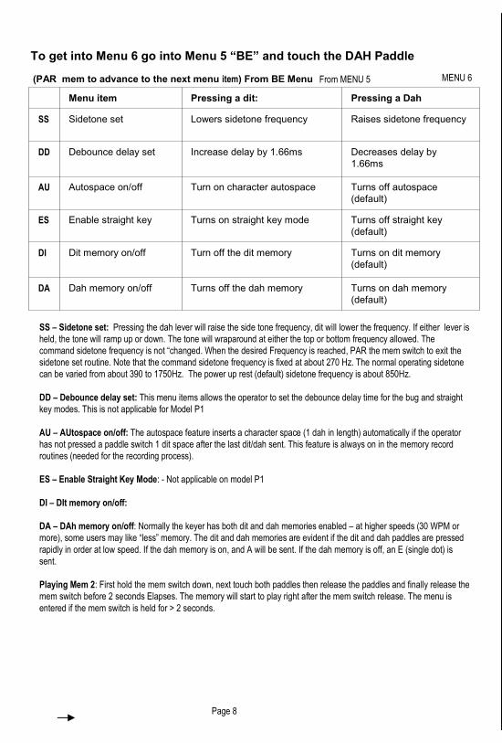
Menu item Pressing a dit: Pressing a Dah
SS Sidetone set Lowers sidetone frequency Raises sidetone frequency
DD Debounce delay set Increase delay by 1.66ms Decreases delay by
1.66ms
AU Autospace on/off Turn on character autospace Turns off autospace
(default)
ES Enable straight key Turns on straight key mode Turns off straight key
(default)
DI Dit memory on/off Turn off the dit memory Turns on dit memory
(default)
DA Dah memory on/off Turns off the dah memory Turns on dah memory
(default)
Page 8
Menu item Pressing a dit: Pressing a Dah
TU CQ Loop mode on/off starts/ends key down advance to “TO” in menu 4
CL CQ Loop mode on/off Turns on the CQ loop mode Turn off the CQ loop (default)
? Record callsign Memory records a dit records a dah
CS CQ Select increases CQs sent by 1 decreases CQs sent by 1
Q /QRP after last callsign selects the /QRP option deselects /QRP (default)
RP RePeat of CQ+callsign increases CQ+CS repeat by 1 decreases CQ+CS repeat by 1
CR Callsign Repeat select increases callsigns sent by 1 decreases callsigns sent by 1
PS PSE suffix to CQ Turns on PSE send after CQ Turns off PSE send (default)
MENU 3
MENU 6From MENU 5
To get into Menu 6 go into Menu 5 “BE” and touch the DAH Paddle

Menu item Pressing a dit: Pressing a Dah
TO TimeOuts
on/off
Turns off the dit/dah tune
timeouts
Turns on dit/dah/tune timeouts
SP Single paddle
Tune on/Off
Turns on single paddle tune
mode
Turns off single paddle tune (default)
H Half PAH delay Sets PAH delay to 1 second Resets PAH to 2 seconds (default)
SF Sidetone Float
mode
Floats pin 3 between
characters
Turns off float (default)
ST Sidetone on/off Turns off Sidetone Turns on the sidetone (default)
AS Accukeyer/CM
OS III
Selects Accukeyer Mode B Selects CMOS Super III (default)
CR - Callsign Repeat: The number of callsigns sent during the CQ + callsign can be varied from 1 to 4 with this menu item
(the default count is 2). PAR of dah will decrease the number of times the callsign is sent by 1 - PAR of dit will increase the
number of times the callsign is sent by 1. PAR of mem will exit the menu and send the number of callsign repeats. The setting
will wraparound the opposite limit when the count goes above 4 or below 1.
PS - PSE CQ mode: A Par of the mem switch will advance to PS. Press the dit lever to turn on the PSE CQ mode. This will
send a PSE before the final K in the CQ sequence. Press the dah lever to turn off the PSE send in the CQ sequence (off is the
default state)
Page 6
(PAR mem to advance to the next menu item) From TU Menu
TO – TimeOuts on/off: To prevent never-ending strings of dits /dahs or didahs caused by a stuck paddle, a timeout mode
has been added to the keyer chip which will put the keyer to sleep if a paddle is held for 128 straight dits, dahs or dits and
dahs. These timeouts default to ON but can be turned off with a dit press
SP – Single lever Paddle tune mode: Not applicable on this model.
H – Half PAH delay length: Some operators may desire a shorter PAH (Press and Hold) delay time to speed up the entry into
various menus. Press a dit to shorten the delay to 1 second. Press a dah to restore the PAH delay back to 2 seconds.
SF – Sidetone Float on/off: The reason for the floating sidetone pin is to minimize thump from the sidetone when the keyer
chip is used to inject sidetone Into a rig audio chain, The float should normally be DISABLED when using a piezo sidetone to
prevent excessive power supply current in the sleep mode.
ST – SideTone on/off: The sidetone will still be engaged during any menu or recording entry and during practice mode even if
it is turned off with this menu Item – this item allows the users to employ his rig sidetone.
AS – Accukeyer or Super CMOS iambic mode B: There are at least two varieties of iambic mode B. The Super CMOS
Keyer (see QST, October 1982) ignores the dit input during the first 1/3 of the dah. The idea is that the operator has a little
extra time to release the dit paddle before a dit is appended to the dah being sent. The Accukeyer (see QST, August 1973)
latches in the dit during the whole of the dah period.
Playing the CQ + Callsign Memory: Play the CQ memory by simulpressing and releasing the memory and the dah keys. I
usually PAH the mem switch And then tap the dah paddle – the memory starts to play after the mem switch is released.
General notes on playing any of the memories: A tap of either a dit or dah paddle will stop the message play (except
during the playing of /QRP). PAH the Mem key during playback to pause the message and the end of the play of the current
character, you can then send manually with the paddles and the Keyer chip will automatically resume message play.
General note on recording MEM 1 and 2: Note that you can insert the callsign memory at any given point in the
message by sending 6 dahs in a row. You can also insert a pause into the memory by recording the AS (di-dah-di-di-
dit) character. Message play will stop when the embedded pause is reached – the paddle can then be used to send
something manually – message play will then resume after a word space length delay. This is useful for inserting
RST or a serial number into the message. You can also embed a space of 6 dits in length by
entering a special character di-dah-dah-dah-dit). Note that spaces do count as characters in the capacity of a
memory. You can insert the callsign memory, pause or space multiple times – each insertion takes up one character
in memory. Also, the operator can “backspace” the memory while recording by a PAR of MEM+dit. The keyer chip
will play the character backspaced over. Note that the three special characters above will be played as recorded (6
dahs, AS and AG) rather that as their functions. Normally the keyer chip will play a word
space (AG) as the first character to be backspaced over. If the operator needs to insert a word space, it can be sent
as an AG or the character previous to the word space can be backspaced over and resent, then the word space will
be automatically inserted after allowing an appropriate time to wait before proceeding with the rest of the recording.
Playing Mem 1: Play the memory with a PAR of the memory switch. The memory will start to play right after the
memory switch is released. Mem 1 is preloaded with the callsign memory at power up but can be re-recorded using
the M? item in the mem menu (see M? explanation)
Recording Mem 1 and Menu: The Mem 1 menu can be entered by a PAH of the mem switch (alone) for 2 seconds.
After 2 seconds the keyer will the Menu (you’ll hear a BE).
Page 7
PAH Mem switch (PAR mem to advance to the next menu item)
Menu item Pressing a dit: Pressing a Dah
BE BEacon mode Starts the beacon going Advance to SS menu item (menu 6)
M? Record Mem 1 Records a dit Records a dah
KD Key Down beacon
delay
Selects key down during the
delay between memory sends
Selects key up (default) during delay between
memory sends
BA Beacon Alternate
mode
Selects alternate beacon
sends of mem 1 and mem 2
Selects send of mem 1 only (default)
D Change the
beacon Delay
Increases delay by 1 second Decreases delay by 1 second
BE - Beacon Mode: Beacon mode will send the contents of mem 1 continuously with a selectable (see D below)
pause in between each play of the memory. Start the beacon by pressing the dit lever - the beacon starts to play.
Exit beacon mode by tapping the dit or dah lever.
M? - Record Mem 1: Start sending your message. when complete, press the mem key. The memory is 80
characters long - recording will terminate automatically after the 80th character.
KD - Key Down beacon delay: Press dit to select the key down beacon delay mode. This will enable the sending of
a constant key down during the interval between sending the beacon message. Press dah to return to the default
key up beacon delay. The keyer will send either a dit or dah and then exit the menu.
BA - Beacon Alternate between mem 1 and mem 2 mode: This routine selects/deselects alternating the beacon
between mem 1 and mem 2.
D - increase the beacon delay: The beacon delay will default to 0 seconds. The maximum beacon delay is 63
seconds. After pressing either dit or dah the keyer will send a dit or dah through the sidetone. When you get to the
desired delay time, press the memory switch to exit from the menu - the keyer will send the delay length through the
sidetone. The routine will “wraparound” from high to low OR from low to high delay values similar to the paddle
speed control. Note that the delay times are approximate. Pressing both paddles at the same time will reset the
beacon delay to zero.
MENU 4
MENU 5
From MENU 3
To get into Menu 4 go into Menu 3 “TU” and touch the DAH Paddle

Menu item Pressing a dit: Pressing a Dah
TO TimeOuts
on/off
Turns off the dit/dah tune
timeouts
Turns on dit/dah/tune timeouts
SP Single paddle
Tune on/Off
Turns on single paddle tune
mode
Turns off single paddle tune (default)
H Half PAH delay Sets PAH delay to 1 second Resets PAH to 2 seconds (default)
SF Sidetone Float
mode
Floats pin 3 between
characters
Turns off float (default)
ST Sidetone on/off Turns off Sidetone Turns on the sidetone (default)
AS Accukeyer/CM
OS III
Selects Accukeyer Mode B Selects CMOS Super III (default)
CR - Callsign Repeat: The number of callsigns sent during the CQ + callsign can be varied from 1 to 4 with this menu item
(the default count is 2). PAR of dah will decrease the number of times the callsign is sent by 1 - PAR of dit will increase the
number of times the callsign is sent by 1. PAR of mem will exit the menu and send the number of callsign repeats. The setting
will wraparound the opposite limit when the count goes above 4 or below 1.
PS - PSE CQ mode: A Par of the mem switch will advance to PS. Press the dit lever to turn on the PSE CQ mode. This will
send a PSE before the final K in the CQ sequence. Press the dah lever to turn off the PSE send in the CQ sequence (off is the
default state)
Page 6
(PAR mem to advance to the next menu item) From TU Menu
TO – TimeOuts on/off: To prevent never-ending strings of dits /dahs or didahs caused by a stuck paddle, a timeout mode
has been added to the keyer chip which will put the keyer to sleep if a paddle is held for 128 straight dits, dahs or dits and
dahs. These timeouts default to ON but can be turned off with a dit press
SP – Single lever Paddle tune mode: Not applicable on this model.
H – Half PAH delay length: Some operators may desire a shorter PAH (Press and Hold) delay time to speed up the entry into
various menus. Press a dit to shorten the delay to 1 second. Press a dah to restore the PAH delay back to 2 seconds.
SF – Sidetone Float on/off: The reason for the floating sidetone pin is to minimize thump from the sidetone when the keyer
chip is used to inject sidetone Into a rig audio chain, The float should normally be DISABLED when using a piezo sidetone to
prevent excessive power supply current in the sleep mode.
ST – SideTone on/off: The sidetone will still be engaged during any menu or recording entry and during practice mode even if
it is turned off with this menu Item – this item allows the users to employ his rig sidetone.
AS – Accukeyer or Super CMOS iambic mode B: There are at least two varieties of iambic mode B. The Super CMOS
Keyer (see QST, October 1982) ignores the dit input during the first 1/3 of the dah. The idea is that the operator has a little
extra time to release the dit paddle before a dit is appended to the dah being sent. The Accukeyer (see QST, August 1973)
latches in the dit during the whole of the dah period.
Playing the CQ + Callsign Memory: Play the CQ memory by simulpressing and releasing the memory and the dah keys. I
usually PAH the mem switch And then tap the dah paddle – the memory starts to play after the mem switch is released.
General notes on playing any of the memories: A tap of either a dit or dah paddle will stop the message play (except
during the playing of /QRP). PAH the Mem key during playback to pause the message and the end of the play of the current
character, you can then send manually with the paddles and the Keyer chip will automatically resume message play.
General note on recording MEM 1 and 2: Note that you can insert the callsign memory at any given point in the
message by sending 6 dahs in a row. You can also insert a pause into the memory by recording the AS (di-dah-di-di-
dit) character. Message play will stop when the embedded pause is reached – the paddle can then be used to send
something manually – message play will then resume after a word space length delay. This is useful for inserting
RST or a serial number into the message. You can also embed a space of 6 dits in length by
entering a special character di-dah-dah-dah-dit). Note that spaces do count as characters in the capacity of a
memory. You can insert the callsign memory, pause or space multiple times – each insertion takes up one character
in memory. Also, the operator can “backspace” the memory while recording by a PAR of MEM+dit. The keyer chip
will play the character backspaced over. Note that the three special characters above will be played as recorded (6
dahs, AS and AG) rather that as their functions. Normally the keyer chip will play a word
space (AG) as the first character to be backspaced over. If the operator needs to insert a word space, it can be sent
as an AG or the character previous to the word space can be backspaced over and resent, then the word space will
be automatically inserted after allowing an appropriate time to wait before proceeding with the rest of the recording.
Playing Mem 1: Play the memory with a PAR of the memory switch. The memory will start to play right after the
memory switch is released. Mem 1 is preloaded with the callsign memory at power up but can be re-recorded using
the M? item in the mem menu (see M? explanation)
Recording Mem 1 and Menu: The Mem 1 menu can be entered by a PAH of the mem switch (alone) for 2 seconds.
After 2 seconds the keyer will the Menu (you’ll hear a BE).
Page 7
PAH Mem switch (PAR mem to advance to the next menu item)
Menu item Pressing a dit: Pressing a Dah
BE BEacon mode Starts the beacon going Advance to SS menu item (menu 6)
M? Record Mem 1 Records a dit Records a dah
KD Key Down beacon
delay
Selects key down during the
delay between memory sends
Selects key up (default) during delay between
memory sends
BA Beacon Alternate
mode
Selects alternate beacon
sends of mem 1 and mem 2
Selects send of mem 1 only (default)
D Change the
beacon Delay
Increases delay by 1 second Decreases delay by 1 second
BE - Beacon Mode: Beacon mode will send the contents of mem 1 continuously with a selectable (see D below)
pause in between each play of the memory. Start the beacon by pressing the dit lever - the beacon starts to play.
Exit beacon mode by tapping the dit or dah lever.
M? - Record Mem 1: Start sending your message. when complete, press the mem key. The memory is 80
characters long - recording will terminate automatically after the 80th character.
KD - Key Down beacon delay: Press dit to select the key down beacon delay mode. This will enable the sending of
a constant key down during the interval between sending the beacon message. Press dah to return to the default
key up beacon delay. The keyer will send either a dit or dah and then exit the menu.
BA - Beacon Alternate between mem 1 and mem 2 mode: This routine selects/deselects alternating the beacon
between mem 1 and mem 2.
D - increase the beacon delay: The beacon delay will default to 0 seconds. The maximum beacon delay is 63
seconds. After pressing either dit or dah the keyer will send a dit or dah through the sidetone. When you get to the
desired delay time, press the memory switch to exit from the menu - the keyer will send the delay length through the
sidetone. The routine will “wraparound” from high to low OR from low to high delay values similar to the paddle
speed control. Note that the delay times are approximate. Pressing both paddles at the same time will reset the
beacon delay to zero.
MENU 4
MENU 5
From MENU 3
To get into Menu 4 go into Menu 3 “TU” and touch the DAH Paddle
TU - Tune mode: After a mem switch PAR the keyer will send TU. Tap (do not hold) the dit lever to enter tune mode (key
down). Exit tune mode by a PAR of dit or dah. The tune mode can also be entered using the 5 didah tune mode (see
notes at the end of this manual. The TUNE period will last for about 15 seconds.
CL – CQ Loop Mode: After 2 seconds the keyer will send CL. Press the dit lever to turn on the CQ loop mode. Then a
mem+DAH will start a continuous send of the CQ sequence, spaced apart by the beacon delay set in the D item of the
mem switch menu. Press the dah to turn off the CQ loop mode. Then the mem+dah will play the CQ sequence only one
time.
? - Record the Callsign Memory: The callsign can now be recorded. When complete, press the memory switch. The
routine will be exited automatically after the 80th character is sent. The callsign memory is saved in EEPROM - it will still
be there even if power is removed. If the mem+dit memory is enabled, it will be possible to overrun it during the callsign
record since the mem+dit memory starts the 41st character of the callsign memory.
CS - CQ select: The number of CQs sent during the CQ + callsign can be varied from 0 to 7 with this menu item. PAR of
dah will decrease the number of times CQ is sent by 1 - PAR of dit will increase the number of times CQ is sent by 1.
PAR of mem will exit the menu and send the number of CQ repeats. The setting will wraparound the opposite limit when
the count goes above 7 or below 1. The reset (default) count is 4 CQs.
Q - /QRP after last callsign: This option will allow the operator to append a /QRP to the last callsign sent - for example:
CQ CQ CQ CQ DE WB9XXX WB9XXX/QRP K. Press dit to select the /QRP option, press dah to return to the default
non-/QRP CQ. The keyer will send either a dit or dah and then exit the menu.
RP - RePeat of CQ+callsign send: The number of times the CQ+callsign is repeated can be varied from 1 to 4 with this
menu item (the default count is 1). PAR of dah will decrease the number of times the CQ+callsign is sent by 1 - PAR of
dit will increase the number of times the CQ+callsign is sent by 1. PAR of mem will exit the menu and send the number of
CQ+callsign repeats. The setting will wraparound the opposite limit when the count goes above 4 or below 1.
Page 5
PAH Mem + dah menu (PAR mem to advance to the next menu item)
SS – Sidetone set: Pressing the dah lever will raise the side tone frequency, dit will lower the frequency. If either lever is
held, the tone will ramp up or down. The tone will wraparound at either the top or bottom frequency allowed. The
command sidetone frequency is not “changed. When the desired Frequency is reached, PAR the mem switch to exit the
sidetone set routine. Note that the command sidetone frequency is fixed at about 270 Hz. The normal operating sidetone
can be varied from about 390 to 1750Hz. The power up rest (default) sidetone frequency is about 850Hz.
DD – Debounce delay set: This menu items allows the operator to set the debounce delay time for the bug and straight
key modes. This is not applicable for Model P1
AU – AUtospace on/off: The autospace feature inserts a character space (1 dah in length) automatically if the operator
has not pressed a paddle switch 1 dit space after the last dit/dah sent. This feature is always on in the memory record
routines (needed for the recording process).
ES – Enable Straight Key Mode: - Not applicable on model P1
DI – DIt memory on/off:
DA – DAh memory on/off: Normally the keyer has both dit and dah memories enabled – at higher speeds (30 WPM or
more), some users may like “less” memory. The dit and dah memories are evident if the dit and dah paddles are pressed
rapidly in order at low speed. If the dah memory is on, and A will be sent. If the dah memory is off, an E (single dot) is
sent.
Playing Mem 2: First hold the mem switch down, next touch both paddles then release the paddles and finally release the
mem switch before 2 seconds Elapses. The memory will start to play right after the mem switch release. The menu is
entered if the mem switch is held for > 2 seconds.
(PAR mem to advance to the next menu item) From BE Menu
Menu item Pressing a dit: Pressing a Dah
SS Sidetone set Lowers sidetone frequency Raises sidetone frequency
DD Debounce delay set Increase delay by 1.66ms Decreases delay by
1.66ms
AU Autospace on/off Turn on character autospace Turns off autospace
(default)
ES Enable straight key Turns on straight key mode Turns off straight key
(default)
DI Dit memory on/off Turn off the dit memory Turns on dit memory
(default)
DA Dah memory on/off Turns off the dah memory Turns on dah memory
(default)
Page 8
Menu item Pressing a dit: Pressing a Dah
TU CQ Loop mode on/off starts/ends key down advance to “TO” in menu 4
CL CQ Loop mode on/off Turns on the CQ loop mode Turn off the CQ loop (default)
? Record callsign Memory records a dit records a dah
CS CQ Select increases CQs sent by 1 decreases CQs sent by 1
Q /QRP after last callsign selects the /QRP option deselects /QRP (default)
RP RePeat of CQ+callsign increases CQ+CS repeat by 1 decreases CQ+CS repeat by 1
CR Callsign Repeat select increases callsigns sent by 1 decreases callsigns sent by 1
PS PSE suffix to CQ Turns on PSE send after CQ Turns off PSE send (default)
MENU 3
MENU 6From MENU 5
To get into Menu 6 go into Menu 5 “BE” and touch the DAH Paddle

W - Weight: Normally the keyer chip will send dits and dahs with a 1:3 ratio. The W menu item will allow the user to change
this ratio. Pressing a dah will decrease the weight, making both the dits and dahs shorter by about .8% of a dit length - an N
is sent for the user to judge the change in weighting.. Pressing a dit will increase the weight making the dits and dahs
longer by about 8% - an A is sent.. Simulpressing the dit/dah will send an R and reset the weighting to zero and re-establish
the 1:3 ratio. Exit the weight routine with a PAR of the mem switch. The maximum weight is about 50% of the current dit
length, 63 total steps higher or lower in weight.
Page 4
P - Select Pot or Paddle speed control: If the keyer is accidentally put into the paddle speed control mode the pot speed
control can be resumed by pressing dit.
C - Calibrating the Pot speed control: Due to the variation in capacitors and pots it is possible that the maximum setting of
the pot will result in a minimum speed higher than 5 WPM. This menu item will compensate and store an updated calibration
value. Before entering the menu, be sure to turn the pot to the minimum speed. Then press the dit to go into the calibration
routine - you then may hear one or more dits and the keyer will exit from the menu. If the pot calibration is run with the pot
above mid-scale, the keyer may jump into paddle speed control if the pot is then turned below mid-scale after calibration is
complete. It won’t be possible to exit paddle speed control because the calibration value is too low. Pressing a Dah will
restore the default power up calibration value and thus allow normal pot speed control again.
TM - Third Memory (enable / record / disable): This option enables then records OR disables an optional 3rd memory. The
callsign memory is then split into two 40 character memories, the third memory is now what was the second half of the
callsign memory. This new third memory is then played with a mem+dit PAR simulpress. Record memory 3 in the same
fashion as the other 2 memories. The speed send is moved into the mem+dit menu as the first item. Press either dit or dah to
exit the mem + dit menu after the speed has been sent.
SO - Speed (send) Off: With a dit press, this menu item turns off the speed send at the end of the paddle speed set menu
item. A dah press will reinstate the speed send.
Recording the Callsign Memory or using the Menu: A callsign (or regular memory) of up to 80 characters long can be
recorded (40 if TM is used). This can be handy for things like: WB9XXX/9 . The callsign memory menu is entered by
simulpressing the memory and the dah keys and holding them for 2 seconds. I usually PAH the memory switch and then tap
the dah key.
B - Bug / Straight-key mode: Press and hold (PAH) the mem switch and both paddles for 2 seconds, then release the
paddles only, keep holding the mem switch until after 2 seconds the keyer will send a B. Press the dah paddle to turn off
bug mode and return to the default.
T? – Record mode 2: The seconds message of up to 80 characters long can be recorded by a PAR of the mem switch,
the keyer will send a T?. Mem 2 can now be recorded. When recording is completed, press the mem switch. If you wish
to skip recording just press and release the mem switch alone to proceed to the next menu.
PR - Practice mode: The output transistor is not keyed but the sidetone is retained. This allows the user to get used to
the model P1 without having to disconnect the rig. Note that PR takes precedence over the ST menu item - even if the
sidetone is turned off with ST, turning on the practice mode with PR will re-enable the sidetone.
L - Live or Dead recording: Normally, the memory or callsign will be recorded by the user off the air (dead) but
sometimes it’s desirable to be able to record a message on the air (live).
A - Iambic mode A or B: The A mentioned above signifies the mode A/B select menu item. The iambic mode of the
keyer can be set to either mode using this routine. Check the JHP web site for an Acrobat (.pdf) file which explains the
difference between the A and B keying modes.
U – Ultimatic mode on/off: Ultimatic is a dual paddle keying mode which predates the now popular iambic A/B modes.
Ultimatic differs in this way from iambic: instead of an alternation between dit and dah when both paddles are pressed,
Ultimatic will output the element of the last paddle pressed. This can be handy for sending characters such as the ?
(press and hold the dit for 2 dits, then while keeping the dit pressed, press the dah for 2 dahs, then release the dah for
the last two dits). Note that the Ultimatic setting takes precedence over either of the iambic modes. A dit will turn on
Ultimatic mode, a dah turns Ultimatic off (default).
R - Reverse paddle mode: Reverses the dit and dah levers (easier than re-soldering a jack).
Page 9
Notes:
To perform a full keyer reset (all memories and parameters to their default value)s:
1) remove power to the keyer
2) PAH the mem switch for several seconds to discharge the capacitors.
3) Power up the keyer with the mem switch depressed until the FB is sent.
Quick tune is a is a quick way to enter tune mode by sending 5 (or more) ditdahs in a row (hold both paddles for at
least 5 ditdahs or dahdits) and then release the paddles. The keyer will then enter the tune mode.
Since there aren’t any normally used characters of this length, this modes should not be actuated during normal
sending.
In Ultimatic mode, PAH both paddles, after nice code elements have been sent the keyer enters the tune mode.
Exit tune mode with a tap of either paddle.
Menu item Pressing a dit: Pressing a Dah
B Bug / straight key
mode
Enables bug mode (dah =
key)
Disables bug mode (default)
T? Record mem 2 Records a dit Records a dah
PR Practice mode Disables the output transistor Enables the output (default)
L Live / dead recording Enables keyer output when
recording a memory
Disables live output (default)
A iambic mode A or B Enables iambic mode A Enables mode B (default)
U Ultimatic mode Turns on Ultimatic mode Turns off Ultimatic (default)
RU Reverse paddle mode Switches dit and dah levers Switches dit and dah levers
PAH Mem + both paddles (PAR mem to advance to the next menu item)
Menu item Pressing a dit: Pressing a dah:
S Speed set from paddle Increases speed by 1 WPM Decreases speed by 1 WPM
W Weight Increases the “weight” Decreases the “weight”
P Pot / Paddle speed Control Selects pot speed control Selects paddle speed control
C Calibrate pot speed control Enters the calibration routine Restores default pot calibration
TM Third Memory Selects the optional 3rd memory - O? is
sent, then the third memory is recorded.
Returns to 2 memories and
exits menu (default)
SO Speed (send) Off Turns off the speed send at the
exit of the S menu item above
Turns on the speed send at
exit of S menu item default)
PAH Mem + DIT menu (PAR mem to advance to the next menu item)MENU 2
MENU 7

WWW.CWTOUCHKEYER.COM
KEYER OPERATION
Operation: General notes on using the switches to control the keyer:
To give the keys multiple functions, multiple key-press combinations are used. Also, the memory switch can be
pressed and released (PAR) OR pressed and held for 3-4 seconds (PAH). This also gives more
combinations of the three control switches (dit, dah and memory switch). Generally, PAR is used for actions: send the
code speed or send a memory. PAH is used for settings: change the code speed (no pot) or record a memory or change
the iambic mode.
4 menus are used for setting various options - they are activated by a PAH of the memory switch alone or plus a
simulpress of dit or dah or both. The menu selections are made by pressing either the dit or dah levers - you will then
normally hear a corresponding dit or dah via the sidetone, the selection will be made and you are then returned back to
normal keyer mode.
In general, the operator can skip a menu item by a PAR of the mem switch. The operator can “bailout” from a menu to
normal keyer operation with a PAH of MEM, then hit both dit and dah, then release MEM. Note that the keyer sidetone
will be lower in pitch for keyer commands such as the menu prompts, recording a memory or the FB sent at power up.
The normal pitch for routine sending or practice is higher.
A function table of the keyer keypress combinations:
Power up: Roughly one half second after power up the keyer will send an FB through the sidetone to signal correct
operation.
Speed Readout: The speed (in WPM) will be played through the sidetone if MEM switch is simulpressed with the dit
lever and then both are released. I normally press the MEM switch first and hold it, press the dit lever and finally release
both.
Speed Control and Menu: The speed can be adjusted by just turning the pot. Maximum speed is 50 WPM, minimum
speed is 5 WPM. Note that the minimum speed can be affected by component tolerances on the timing capacitor and
the speed pot - see the pot calibration menu item if a 5 WPM minimum speed is required. The pot position is read
continuously when the keyer is sending code, just before each dit, dah or space is sent. This allows the operator to
adjust the code speed even in the middle of a memory send or record.
If you disconnect the pot from the circuit, the keyer will power up at a default speed of 21 WPM. The speed can be
adjusted by pressing and holding the memory switch along with the dit lever. Usually I PAH the memory switch and then
tap the dit lever. After 2 seconds, the keyer will send an S (for speed set). Press the memory switch to advance to the
next menu item without changing the speed. Or, pressing the dit lever will increase the speed by 1 WPM and send a dit.
Pressing the dah lever will decrease the speed by 1 WPM and send a dah. You can continuously adjust the speed by
holding either lever but note that if you run the keyer “off the scale” at either 5 or 50 WPM, the keyer will “wrap around”
to the opposite speed extreme. Exit the speed adjust routine by pressing and releasing the memory switch - the code
speed will be sent via the sidetone upon exit (see the SO menu item below to turn off this speed send).
Keys used PAR (press and release) PAH (press and hold)
MEM switch Send MEM 1 Record MEM 1 and beacon options
MEM + dit Send speed or MEM 3 Paddle set of speed, pot options, record MEM 3
MEM + dah Send CQ or callsign Tune, record callsign & CQ options
MEM both Send MEM 2 Tune, record callsign & CQ options
Page 3Page 10
MENU 1

1. Lay the board assembly on a non-conductive surface.
2. Place switch in the off position (DOWN).
3. Connect ohm meter to ground point.
4. Connect the DC power source.
5. Flip switch on (up).
6. Measure for 5 volts at point A (VCC)
7. Measure the resistance at point B TP1. (Should be Infinity)
Touch the Right paddle and the resistance should drop below 5 ohms.
8. Measure the resistance at point C TP2. (Should be Infinity)
Touch the Left paddle and the resistance should drop below 5 ohms.
9. Measure the resistance at point D TP3 (Should be Infinity)
Touch the Left or right paddle and the resistance should drop below infinity to some
value based on the code speed.
Ground
B TP2
C TP1
A 5 Volts
D TP3
Page 2
Trouble Shooting
Be sure all leads on the bottom side of the PC board are properly soldered, and clipped short.
Be sure to clip the leads of the switch, speed pot, & MEM.
Have a voltmeter ready to perform test.
Installing the 9 volt transistor battery:
A 9 volt transistor battery can be installed inside the case of the Model P1 by removing the two bottom cover screws and
lifting the top cover off.
The Model P1 draws less than 2 ma of current in standby mode and can spike up to 14 mA while sending using the
internal speaker. If the unit is connected to an external speaker the current consumption can jump up to 22 mA peak
during code sending, depending on the set volume.
It is recommended that if an external speaker is being used, turn down the volume of the internal speaker to conserve
power. Note: When the unit is first tuned on a “FB” code will be sent.
Volume
Pot
Page 11
Battery Saver Circuit – on model P1BSW only
If you ordered model P1BSW (with battery the battery saver circuit ) your
model will have a momentary push button switch and LED on the front panel.
To turn the unit on, simply press and release the push button. The LED will light for
about 10 seconds and shut off. This indicates the unit is active and ready to use.
Your unit is now active for 10.5 minutes and will automatically shut off
(disconnecting the battery from the circuit) after that time period.
If the left paddle is touched, with two consecutive dots, at any time during the
10.5 minute period, the unit will reset itself for another 10.5 minutes.
To shut the unit off, just let it sit (untouched) for 10.5 minutes.
LED INDICATOR.
3 blinks – less than one minute remains before the unit will shut off.
5 blinks – low battery
LOW BATTERY:
If LED indicator blinks 5 times while the unit is turned on, that’s indicating your
9V power source (battery) is lower than 6.3 volts.
If at any time during the 10.5 minutes the LED starts to blink 5 times, it’s
an indication your battery has now run low and should be replaced.
Once this low battery indication starts it will repeat itself (blinking 5 times)
once every minute until the battery is replaced.
You still have about 2 hours of battery use before the battery will drastically
drop low enough for the unit to malfunction.
Last Minute Warning
During the 9th minute of inactivity, the LED will begin to blink 3 times every 10
seconds as a reminder to touch the left paddle.
Once the left paddle is touched, the timer will reset for an additional 10.5 minutes.
HARD RESETIf the unit seems to act up, you can perform a HARD RESET by first turning the unit off.
Remove the battery or power source. Wait 10 Seconds and replace.
Then with the MEM button pressed in, turn the unit on by pressing the front panel push button.
Release the MEM button.
This will wipe out any and all memory and settings and place the unit back into it’s default
mode.
Remember to recalibrate once this is done.

The power plug is a 2.1mm center pin power jack. All other jacks are 3.5 mm stereo.
Be sure when assembling the power plug that the positive lead is attached to the center conductor of the plug.
Double check to be sure!
Model P1 Touch Paddle KeyerOperation Manual www.cwtouchkeyer.com
Question and Support: [email protected]
Thank you for selecting and purchasing the Touch Paddle Keyer model P1.
Operation:
-Before connecting the power supply to the model P1 place the power switch in the off position (down).
-Connect power supply, 9 – 14VDC, to the 2.1mm power jack located in the rear of the unit or internal 9V battery.
-Remove the case top by removing the two recessed screws on the bottom of the unit.
-Flip the power switch on (up).
-Immediately upon power up you should hear a CW code “FB” followed by silence on the internal mini speaker.
a) If no code is heard either the volume control, located inside the unit, is turned down or the unit is not functioning
properly. If no sound can be heard turn the unit off and contact [email protected].
REAR PANEL
MEM Button – This is the memory programming switch.
Pwr Input – Power jack. 2.1mm. 9 – 14 VDC. Center pin is POSITIVE
Keyer Out (Output for electronic keyer) – 2 wire key out to transmitter. 3.5mm jack. Sleeve is ground, tip is key. (ring is
not used)
Paddles Out – (Paddle output only, no electronic keyer) Used in conjunction with an external keyer. Sleeve is ground,
ring is dash, tip is dot.
Spkr Output – Connect to an external 8 ohm speaker or audio amplifier. Sleeve is ground, ring and tip are tied
together. This will produce a louder volume than the internal mini speaker.
Page 1
BACK PANEL
SPKR
OUTPUT
Paddles
OUT
KEYER
OUT
MEM
BUTTON6-14 VDC
PWR INPUT
2.1mm
Power Jack
3.5mm
Plug
SpeakerGround
Not used
DashDotGround
NOTE: This keyer output circuit is designed to switch
key input of 13.8 Volts positive or less. This is normal
for most type of transistor type keying.Do not attempt to
use the this output with a vacuum tube
transmitter (either grid blocked or cathode keyed).
Electronic Keyer Programming tips.
MEM – This is the MEMORY button used in programming the keyer
PAH – Means PRESS AND HOLD for 3-4 seconds
PAR – Means PRESS AND RELEASE
When the manual calls for a PAH of a MEM and paddle, press in on the MEM button and touch the
paddle at the same time and HOLD, until you hear the appropriate code from the menu you are
working on, then release both.
Once you get into a menu, PAR (press and release) the MEM button to advance to the next menu
item. Do not touch the DOT or DASH paddle until you get to the menu item you want and then
touch the appropriate paddle for your setting.
Once a setting is made, you will automatically be exited from the menu. If you require a second
setting re-enter the menu from start.
Menus are numbered 1-7.
Menu 4 cannot be entered direct and must be entered through Menu 3.
Menu 6 cannot be entered direct and must be entered through Menu 5.
It is highly recommended that you calibrate the speed pot when first used. This is found on menu 1,
menu item “C”.
Tips
A quick way to place the keyer into the TUNE mode is to press and hold both
the DOT and DASH paddles until it sends 6 DOT/DASHS. Then release and the
paddles and the unit will automatically go into the tune mode for about 15
seconds. Touch either paddle and the TUNE mode will shut off.
If the unit seems to act up, you can perform a HARD RESET by first turning the
unit off. (see page 11 for model P1BS)
Then with the MEM button pressed in, turn the unit on. Release the MEM button.
This will wipe out any and all memory and settings and place the unit back into it’s
default mode.
Remember to recalibrate once this is done.
Bottom Cover
TAB
REMOVE THESE SCREWS
TO OPEN CASE
Positive
Negative
GroundPositive
Not used
NOTE: The keyer output transistor circuit is design to switch key input of 13.8 Volts positive
or less. Do not attempt to use any CW Touch Keyer products with a vacuum tube transmitter
(either grid blocked or cathode keyed) without an appropriate output circuit.
Consider purchasing the “keyall” kit from Jackson Harbor Press for tube type keying.
http://jacksonharbor.home.att.net/keyall.htm
See Page 11 for model P1BSW – Battery Saver