Embed Size (px)
Citation preview

Copyright 2008 Continental Controls Corporation
Revision 2.6 March 2010
Electronic Gas Carburetor
Installation and Operation Manual
Class I, Division 2, Group B, C, D: T3 ISO 9001:2008
CERTIFIED

I
PREFACE
This manual provides instruction and maintenance information for the EGC Electronic Carburetor.
It is highly recommended that the user read this manual in its entirety before commencing operations. It is the policy of Continental Controls Corporation that it is neither our intention nor our obligation, to instruct others on how to design or implement engine control systems. Continental Controls Corporation will not assume responsibility for engine controls which are not designed or installed by our authorized representatives.
This manual is intended to help the end user install and operate the EGC.
Do NOT attempt to operate, maintain, or repair the fuel control valve until the contents of this document have been read and are thoroughly understood.
Every attempt has been made to provide sufficient information in this manual for the proper operation and maintenance of the EGC Electronic Carburetor.
All information contained within shall be considered proprietary information and its release to unauthorized personnel is strictly prohibited.
If additional information is required, please contact:
Continental Controls Corporation
8845 Rehco Road San Diego, CA, 92121 (858) 453-9880

II
SAFETY WARNING! The iContinental Controls Fuel Control Valves are normally used with natural gas. Natural Gas and Air, when combined together, become very combustible and when contained within a confined space, such as an engine enclosure or of a building, can explode in a violent manner when ignited. It is necessary to always use extreme caution when working with any fuel system. Controls for Gas Engines should always be designed to provide redundant fuel shut downs. The EGC will shut off enough fuel to stop the engine from running but it should not be considered a primary shut off valve.
The EGC is NOT a shutoff valve. Shutoff valves should be used in addition to the Electronic Carburetor EGC. The fuel system should be designed in such a way that:
1. No single failure of a component will cause the fuel system to admit fuel to the engine when the engine has been shutdown.
2. No single failure can result in grossly over-fueling the engine.
3. Do not allow fuel to the engine until the ignition system is turned on.
Failure to follow the above rules may lead to possibly serious damage to equipment and/or injury to personnel!
WARNING!!!
DO NOT ATTEMPT TO REPAIR THE ELECTRONIC GAS CARBURETOR IN THE FIELD. THE ELECTRONIC GAS CARBURETOR MUST BE RETURNED TO CONTINENTAL CONTROLS CORPORATION FOR REPAIR AND SERVICES. When installing the EGC in Class I Division 2 Hazardous Location, installation of all electrical Equipment MUST be in compliance with the National Electric Code (NEC). Customer is responsible for termination of pigtail wires out of the Cable Harness Assembly on the EGC. The EGC cables MUST be continuously supported and protected against physical damage using mechanical protection such as dedicated struts, angles or channels. The EGC cables MUST be secured at intervals not exceeding 1.8 meters (6 feet).
Do not connect or disconnect EGC unless power has been switched off.

III
Table of Contents
PREFACE I
SAFETY WARNING! II
TABLE OF CONTENTS III
INTRODUCTION TO AIR FUEL RATIO CONTROL FOR GAS ENGINES 1
BACKGROUND 1
RICH-BURN COMBUSTION 2
LEAN-BURN COMBUSTION 3
INTRODUCTION 5
PURPOSE OF THIS MANUAL 5
TERMS 6
THEORY OF OPERATION 7
FEATURES OF THE EGC 15
SIMPLICITY 15
MECHANICAL VALVE DESIGN 15
RANGE 16
CLOSED LOOP PRESSURE CONTROL 17
FULLY AUTOMATIC CONTROL 17
VARIABLE DYNAMIC GAIN 17
COMMUNICATIONS 17
INSTALLATION INSTRUCTIONS 18
THE EGC VALVE 18
INSTALLATION 19
O-RING 19
BUTTERFLY/GOVERNOR ASSEMBLY 19
FUEL SUPPLY 21 ADJUSTING MIXING VENTURI 22 SOFTWARE OVERVIEW 24 TROUBLESHOOTING EGC 40
PRODUCT WARRANTY 44
APPENDIX A: ENVELOPE DRAWING 45 APPENDIX B: CONNECTOR LOCATIONS 46 APPENDIX C: EGC WITH FLOW VECTORS 47
APPENDIX D: WIRING DIAGRAM 48
APPENDIX F 50
LIST OF RECOMMENDED ACTUATORS 50 CARBURETOR SPECIFICATIONS 51

1
Introduction to Air Fuel Ratio Control for Gas Engines
Background Years ago, before exhaust emissions were a concern, the natural gas engines used mainly by the natural gas industry, were designed to run with 2% to 4% excess air. The air-fuel ratio controllers were mechanical devices that were not very accurate. The air-fuel ratio would often vary with load and as long as the engine would carry the load and didn’t detonate or miss-fire, this was considered expectable.
Later when exhaust emissions became important, it was discovered that these engines were running with very high NOx levels, sometimes at the peak of the NOx curve. Two strategies evolved to reduce the NOx while containing the CO and unburned hydrocarbons. The first strategy is Stoichiometric or Rich-Burn combustion with a catalytic converter. The second strategy is Lean-Burn Combustion. The picture on the next page is representative of the Cylinder Pressure on the vertical (Y-axis) and the ratio of actual air-fuel ratio divided by the stoichiometric air-fuel ratio on the horizontal (X-axis). The graph is not to scale and does not represent any particular engine. The Excess Air Ratio on the X-axis is referred to as Lambda. Stoichiometric air-fuel ratio is 1.0 in the figure 1. Rich-burn operation is Stoichiometric and to the left of the stoichiometric point and Lean-burn operation is to the right of the Stoichiometric point. As can be seen in the figure, the excess air ratio, Lambda, needs to be much higher than 1.0, to reduce the NOx significantly. Operation in the detonation (or knock region) and the incomplete combustion region, must be avoided. In the graph, it can be seen that the engine can be operated at a higher load or BMEP, without detonating, when operating with a large amount of excess air. The higher BMEP means, more horsepower is available and the engine will be a little more efficient because of the higher cylinder pressure.
Chapter
1

2
Fig 1
Rich-Burn Combustion The first method, and easiest to implement, is to operate the engines at a Stoichiometric fuel mixture. This is also referred to as “rich-burn” operation. A Stoichiometric mixture is the chemically correct fuel mixture for combustion, with near-zero oxygen left over in the exhaust. This method of operation is suitable for a three-way catalytic converter. The mixture must be precisely controlled in order for the reaction in a catalytic converter to oxidize the CO to COXYGEN and reduce the NO and NOXYGEN to N2 and OXYGEN and not have undesirable products left over.
Rich-Burn Oxygen Sensor In order to achieve the precise mixture required for the catalyst, an
oxygen sensor must be placed in the exhaust before the catalytic converter. The voltage output of the OXYGEN sensor is fed back to the control device to close the loop on the amount of oxygen in the exhaust. The mixture is controlled to maintain very low oxygen content in the exhaust, and less than 0.02% oxygen. This results in combustion that is consuming nearly all of the oxygen. If higher oxygen content is indicated, the engine is running too lean and lower oxygen content indicates the mixture is too rich.
Benefits of Rich-Burn One of the benefits of engines running in a Rich-Burn mode, with a
catalytic converter, is that they operate with very small quantities of NOx emissions and CO in the exhaust.
NOx in the range of a few parts per million is achievable.

3
Lean-Burn Combustion The second strategy for reducing emissions is to run the engine with as much excess air as possible. To prevent either knocking or misfiring, the combustion process must be controlled within a narrow operating window. In Fig. 1, the operating window is a very narrow band where efficiency peaks and where NOx is near its minimum. Too rich of a mixture can potentially produce detonation and higher NOx emissions. Too lean of a mixture may not combust reliably and because misfiring, which raises HC emissions. An accurate air/fuel ratio controller is critical for maintaining combustion within these boundaries. If a power cylinder has more air compressed into it, the specific heat of the charge in the cylinder is higher, which means, it can absorb the same quantity of heat with less of a temperature rise. The reduction in temperature causes a reduction in the oxidation of the nitrogen. Engines running with large amounts of excess air can achieve levels of NOx below 1 g/hp-hr without a catalytic converter. A selective catalytic converter can be used to reduce the NOx level further, but has the disadvantage of requiring the injection of urea or ammonia.
Lean-Burn Oxygen Sensor: Unlike the oxygen sensor used with Rich Burn, the oxygen sensor
used for Lean Burn engines indicate a very wide range of oxygen in the exhaust and are often referred to as a wide range or Lambda sensor. Lambda is the air-fuel ratio that the engine is running at, divided by the Stoichiometric air-fuel ratio.
Benefits of Lean-Burn: Engines running in the Lean-Burn mode offer several important
advantages: LOWERED COMBUSTION TEMPERATURES
There is an incorrect interpretation concerning lean-burn engines and lower exhaust temperatures. Natural gas engines will always run cooler when running at greater than lambda 1.4. Diesel engines running on liquid fuel will run hotter under lean conditions; because the liquid fuel atomizing helps cool the cylinders, natural gas engines do not have the liquid to atomize, so injecting more fuel does not increase cooling. Lean-burn engines run with excess air that carries the heat out of the cylinders. The more excess air, the greater the cooling effect.
LONGER ENGINE LIFE
Running the engine with lower exhaust temperatures reduces wear to the engine and increases time between overhauls. Lower temperatures also reduce the breakdown of lubricants and decrease the amount of ash accumulation in the oil.
INCREASED EFFICIENCY
It is generally accepted that running lean increases fuel efficiency. Field testing performed by Continental Controls has shown widely varying results from 2% to 28% fuel supply. The negative to running lean is that the maximum engine horse power must be de-rated on engines that are not capable of achieving enough excess air at full load.
REDUCED EMISSIONS

4
Operating with a lean mixture can significantly reduce emission in the exhaust. Lean-burn gas engine generators can have NOx emissions as low as .85 grams/bhp and hr and produce low amounts of hydrocarbons (HC), carbon monoxide (CO) and particulate matter (PM). This often allows engines to meet air quality regulations without after treatment devices in the exhaust stream. For even lower emissions, lean-burn gas engines can be equipped with after treatment options such as Selective Catalytic Reduction (SCR) and Oxidation Catalysts, resulting in NOx levels at or below 0.85 grams/BHP-hr. With these after treatment options, gas engines have been shown to meet the most stringent prime power emissions regulations anywhere in the world.
FUEL FLEXIBILITY
Another advantage of the lean-burn technology is the ability to operate on wide range of gases. A measurement called the Methane Number (MN) is used to determine fuel gas suitability as an engine fuel. Most natural gas has an MN from 70 to 97, and pipeline quality gas typically has an MN of about 75. Resource recovery gas from landfills or sewage treatment facilities is typically of lower quality, but is often suitable for use in lean-burn engines. Some lean-burn gas engine generators will operate on gas with an MN as low as 50, providing excellent fuel flexibility. However, gas with a MN below 70 may require de-rating of the engines output.
5
Introduction
Purpose of this Manual
This manual is designed to describe the installation and operation of the EGC for either rich or lean-
burn applications on gas engines. The EGC and Valve Viewer software represent the current state of
the art in Air Fuel Ratio Controllers. The combination of a sophisticated mixing Venturi and a very fast
and efficient electrically-actuated fuel valve provide a combination that will lower emissions and
improve fuel economy.
Our goal is to provide a complete understanding of how to install and maintain the EGC, with easy to
follow instructions on wiring and set up. Most of the settings in the EGC are factory set and ready to use
in a lean-burn application. To run rich-burn the oxygen sensor setpoint and the venturi must be
adjusted.
Chapter
2

6
Terms
Stoichiometric (Rich-Burn)
• Theoretical air/fuel ratio where all the fuel and all the oxygen in the mixture will be consumed leaving no oxygen in the exhaust.
Lean-Burn
• An internal combustion of lean air-fuel mixtures. Lean-Burn happens at very high air-fuel ratios, so the mixture has considerably less amount of fuel in comparison to Stoichiometric combustion ratio.
Air / Fuel Ratio
• The ratio of mass air rate to mass fuel rate Lambda
• Operating air/fuel ratio
• Stoichiometric air/fuel ratio
• Lambda = 1.0
• > 1.0 = Lean, or fuel-limited combustion.
• < 1.0 = Rich, or air-limited combustion. Sensor (Oxygen - Lambda)
• An exhaust-sensing device (spark plug size) sensitive at stoichiometric air/fuel ratio (Lambda 1.0). Outputs a low signal when lean of lambda and a high signal when rich of lambda. The signal can be utilized to drive automatic air/fuel ratio controllers.
• Characteristic: 0.1 to 0.9 volts output, high output impedance when cool, very sensitive at Stoichiometry.
• Uses a zirconium element, which produces a voltage potential when the partial pressure of oxygen on one side of the element is very small relative to the other side. This element has a catalyzing outer layer, which promotes complete combustion of oxygen prior to reaching the zirconium element.
NOx Oxides of Nitrogen (NO and NOXYGEN) CO Carbon Monoxide THC Total Hydrocarbons Carbons VOC Volatile Organic Compounds) Rich Combustion < 1% OXYGEN Lean Combustion > 4% OXYGEN Excess Oxygen > 10% OXYGEN Three-Way Catalyst
• Contains both reduction catalyst materials and oxidation materials, and will convert NOx, CO, THC to CO2, N and a little H2O and O2.
Supply Pressure The Fuel Gas supply pressure immediately upstream of the EGC.

7
Theory of Operation
The EGC is a culmination of years of development of an advanced gas valve along with a mixing venturi combined with superior application software. The seamless integration of all of these aspects of design into a single integrated product has helped to establish the EGC as the leading controller for reducing emissions for small-gas engines.
Configurations
The EGC is available with and without speed control. The control logic, sequencing, and wiring differ between the two. We have broken this area of the manual into two different sections for each type of configurations. EGC’s with speed control are marked with a “GOV” on the name plate. In this document EGC with speed control will be referred to as governor units. And EGC without speed control will be referred to as non-governor units.
Control Schemes
Non-governor units with oxygen sensor:
Inputs:
The EGC with oxygen sensor requires a peak current of 6ii amps and nominal of 3 amps at 12 volts.
The EGC needs an indication that the engine is starting or running. This is provided by a 12 volt input, referred to as the “Ignition confirm”. This is an “enable signal” to allow the carburetor to emit fuel to the engine. This signal typically is connected to the low oil pressure switch. The criterion for the signal is that it turns on when starting the engine, and turns off when the engine stops. Connecting it to the ignition key is not recommended because the signal would not automatically turn off if the engine would stop unexpectedly.
The second signal available is an input that disables the air to fuel ratio control, and forces the EGC into default or pressure control mode. This is useful when running an engine outside of the range where the oxygen sensor is inaccurate, or instable (e.g. during starting).
The oxygen sensor: Although running an engine with a wide band oxygen sensor is the preferred method, the EGC has the capability of running either with a wide or narrow band sensor. Narrow band sensors operate from 0 volts to 1 volt, and can be used only in Stoichiometric (rich-burn),
Chapter
3

8
applications. Wide band sensors have a 0 to 5 volt signal, and can be used in rich or lean-burn applications.
Sequencing and logic for non-governor units:
The EGC will stay closed until 12 volts is applied to the [ignition confirm] input, indicating the engine is starting. During starting and until the {warm up timer} expires the carburetor acts as a pressure regulator. The carburetor controls the {default pressure} or starting pressure to the fuel inlet of the venturi. When the {warm up timer} has expired and the [OXYGEN sensor] is active, the carburetor will switch to (Air to fuel ratio mode) and start varying the fuel pressure to control the air to fuel ratio. If the oxygen sensor is disconnected, the engine will continue to operate in default mode indefinitely. While in default mode the status light will blink green/red. The pressure that the EGC will control to is limited by the min and max pressure settings, so if the engine misfires, or there is an exhaust leak, or the oxygen sensor fails, the carburetor will control to one of these limits. If the EGC is on a pressure limit the status light will blink red. Engines running in lean mode may still be operating in compliance, while operating on the pressure limit.
It is highly recommend that the customer install an automated shutoff valve upstream of the EGC that closes when the engine is stopped, to provide a redundant gas shut off.
Status light:
Blinking green – Normal operation. Stopped or controlling in Air to fuel ratio mode.
Blinking red/green – Running in default. Starting or waiting for oxygen sensor to become active.
Blinking red – Operating on pressure rail. Either the oxygen sensor has failed or the pressure rails are incorrectly set.
The light bar on the right side of the face plate is a pressure indication. For best performance the EGC should be adjusted so the operating point is near-zero. (See adjusting the mixing venturi)
The EGC delays turning on the oxygen sensor heater to allow the exhaust to remove the condensation off the sensor. In doing this the EGC eliminates the cracking of the ceramic element within the oxygen sensor due to thermal shock.

9
EGC inputs and sequencing for non-governor units (Summarized)
Note:
Items in [squire brackets] are physical 12 volt inputs.
Items in {curly brackets} are software settings and can be modified by the customer.
Engine stopped:
[Ignition Confirm] is off
[Sensor Ignore] is on
EGC is closed, no fuel.
Engine starting:
[Ignition Confirm] is] is on
[Sensor Ignore] is on
EGC is controlling pressure at the {Default Pressure} setting.
{Warm-up Timer} started.
Engine running in default mode
(EGC delays turning on the oxygen sensor heater until timer expires)
[Ignition Confirm] is on
[Sensor Ignore] is on, or {Warm up Up Timer} is greater than zero., or OXYGEN voltage =0
EGC is controlling pressure at the {Default Pressure} setting.
Engine running in air to fuel ratio mode
[Ignition Confirm] is on
EGC is varying the pressure at the venturi to control the oxygen sensor reading to the
{Oxygen set Set Point}.
OXYGEN sensor is greater than 0 volts, and [Sensor Ignore] is off, and {Warm up Timer} ` is zero.

10
Governor units:
Inputs:
The EGC with governor and oxygen sensor requires a peak current of 10 amps and nominal of 4 amps at 12 volts.
The EGC needs an indication that the engine is starting or running. This is provided by the magnetic pickup located on the flywheel. Once the engine is turning greater than the {crank speed} setting, the carburetor emits fuel to the engine. When the engine stops, the EGC closes.
If you have the governor option in your EGC the carburetor should be connected to the throttle body from CCC or a linear actuator connected to a butterfly valve inside a throttle body (see wiring diagram). The throttle body idle screw should be set slightly open so the engine will start and idle with the butterfly closed against to idle set screw. If set too far open, the engine will accelerate past the set point or possibly over speed the engine.
There are two 12 volt inputs that can be connected to a three-way switch to increase or decrease the speed set point. (See wiring diagram). Connecting these inputs are optional and only needed if the engine is not running at a single fixed speed.
The oxygen sensor:
Although running an engine with a wide band oxygen sensor is the preferred method, the EGC has the capability of running either with a wide or narrow band sensor. Narrow band sensors operate from 0 volts to 1 volt, and can be used only in stoichiometric (rich burn), applications. Wide band sensors have a 0 to 5 volt signal, and can be used in rich or lean-burn applications.

11
Sequencing and logic for governor units:
Items in [squire brackets] are physical 12 volt inputs.
Items in {curly brackets} are software settings and can be modified by the customer
The EGC will start to emit fuel to the engine when the engine speed is greater than {crank speed} typically 50rpm.
After the engine accelerates passed 500rpm {idle speed} and the {idle delay} expires the EGC will control the engine speed at the {minimum speed}.
Increasing or decreasing the speed set point is done by Applying 12 volts to the [increase or decrease inputs]. The speed range is limited by the {minimum speed} and {maximum speed} settings. The speed set point rate of change is set by the {ramp rate}. The lower the number in the {ramp rate} the faster the engine will change speed.
There is also an {over-speed shutdown} setting. This is typically set ten percent higher than the maximum normal operating speed. Good safety practices dictate that this over-speed shut down not be treated as the primary shut down, because an over speed condition is usually caused by the governor or speed signal failing. Therefore, the governor may not be able to see the over-speed condition, or react to it. CCC recommends a redundant over-speed shut down be installed in all applications.
The EGC is configured to read up to 4000 rpm. If the engine must run faster than that, a special unit can be calibrated by the manufacture to accommodate it.
The logic in how to shut the engine down remains the same. This is usually done by killing the ignition system. The EGC will close, shutting off the gas, when the engine speed drops below the crank speed. It is highly recommend that the customer install an automated shutoff valve upstream of the EGC that closes when the engine is stopped, to provide a redundant gas shut off.
Status light:
Blinking green – Normal operation. Stopped or controlling in Air to fuel ratio mode.
Blinking red/green – Running in default. Starting or waiting for oxygen sensor to become active.
Blinking red – Operating on pressure rail. Either the oxygen sensor has failed or the pressure rails are incorrectly set.
The light bar on the right side of the face plate is a pressure indication. For best performance the EGC should be adjusted so the operating point is near zero.

12
EGC inputs and sequencing for governor units (Summarized)
Engine stopped:
Engine RPM is below {Crank Speed}
EGC is closed, no fuel.
Engine starting:
Engine RPM is greater than {Crank Speed}
EGC is controlling pressure at the {Default pressure} setting.
{Warm up timer} started.
Engine running at idle in default mode
EGC delays turning on the oxygen sensor heater until timer expires
Engine RPM is between the {Minimum Speed} and {Maximum Speed}
and above {idle speed}.
EGC is controlling pressure at the {Default Pressure} setting.
Engine running in air to fuel ratio mode
EGC is varying the pressure at the venturi to control the oxygen sensor reading to the
{OXYGEN set point}.
OXYGEN sensor is greater than 0 volts, and {Warm up Timer} has expired, and the engine is running above {Crank Speed}

13
Panel Gauge
During operation of the EGC the panel gauge will be your primary indication the engine is running in the correct air to fuel ratio.
The gauge can display lambda or the ratio between fuel and air. The display cannot be configured with the Valve Viewer software. It can only be configured with the Innovate XD 16 software under LM programmer. When displaying Lambda, Stoichiometric is near 1.00 (+/- .01). When running lean, the gauge will display from 1.25 to 1.60. If configured to display fuel to air ratio, the gauge will display 17.2 when at Stoichiometric air to fuel ratio, and when running lean the ratio will be over 21.00.
Other messages you can see over the display are:
Dashes ( - - - ), Normal condition when to O2 sensor is off, for example the engine is shut down or during warm-up cycle. .
H followed by a number. (e.g. H 2 4), indicating the EGC is doing a free air calibration of the O2 sensor.
E1 O2 sensor heater shorted, Replace o2 sensor.
E2 O2 sensor heater disconnected or open. Check connection, or replace o2 sensor.
E3 Battery voltage too low for o2 sensor to function. Check or replace battery and/or charging system.
E4 Free air calibration timed out. Replace O2 sensor.
E5 Free air cal failed. Replace O2 sensor.
E6 Battery voltage low warning Check or replace battery and/or charging system..
The oxygen sensor will display 20.8 to 20.9 oxygen if the oxygen sensor is in the open air.

14
Sensor calibration: (Free air cal)
Every time you replace the oxygen sensor it is necessary to do a free air calibration. Continental Controls recommends you replace your oxygen sensor every 1600 hours. About two months of constant operation. This is the equivalent of driving 96,000 miles at 60 miles per hour. It may be required to replace the oxygen sensor more frequently depending on conditions. The display will indicate a failed oxygen sensor if replacement is required.
The following is a procedure for doing a free air cal:
1) Install a new oxygen sensor or remove the existing oxygen sensor from the exhaust, exposing it to the open air.
2) Apply power to the EGC
3) Dashes ( - - - ), should be visible on the panel gauge.
4) Press the calibration button on the gauge three times.
5) CAL should be flashing on the panel gauge.
6) Press the calibration button on the gauge one more time.
7) The EGC will start a sixty second timer. When completed the O2 sensor has been calibrated.
Warning: The oxygen sensor will become very hot during the sensor calibration.

15
Features of the EGC
Simplicity
Simplicity is the key. If a system is too difficult to setup, install or use, all of the features in the world won’t help.
The EGC is extremely easy to setup and use. At its simplest, the user would merely set the default pressure and use the default gain settings and they will probably be able to control the engine.
Mechanical Valve Design Unlike many of the valves used in competing emissions control systems, the EGC was specifically designed for small reciprocating engines using gaseous fuels. It is not a modified pressure regulator, a biasing restrictor, or a valve borrowed from a different market sector or manufacturer. The valve was completely designed by Continental Controls Corporation for a specific application. Every valve is manufactured at our center in San Diego California. The following are some of the key mechanical design features that contribute to the superior performance of the EGC.
Full Fuel Authority
The EGC meters all fuel entering the engine from no flow to full flow. This prevents the valve from running out of range in difficult applications such as those with large swings in the heating value of the gas. This feature also enables the valve to change the fuel flow very quickly in response to load transients. The full fuel authority of the EGC is primary to keeping the emissions within required limits under all conditions.
Mixing Venturi
The Mixing Venturi is designed to take the place of the mixing bowl in the conventional carburetor. It was designed to provide just the proper amount of fuel based on the current intake of air and thoroughly mix the two together prior to admission into the fuel manifold, and eventually to the engine for combustion.
Chapter
4

16
Range The EGC is a true full authority fuel valve; the range of the EGC is much greater than system relying on a pressure regulator with a bypass valve or a restrictor stepper motor.
The incredible range of the EGC will help tremendously when working with applications where any of the following may occur:
Load Changes
BTU Value of the fuel gas changes
Ambient Air Temperature Changes
By pass type systems are normally set up on the lean limit and they add fuel to control in the desired range. In the event that a large load is removed the system cannot control beyond this lean limit. In the event that the BTU value of the gas declines, the unit sometimes cannot add enough fuel to keep up with the change. This control range on a bypass type system is normally a maximum of 10% to 15% change.
A restrictor valve type of system is normally set up to run rich and the restrictor valve pinches off fuel to control in the acceptable range. This system also lacks the range to keep up with large load changes or BTU swings.
High speed actuator
At the heart of the EGC is a high-speed, electromechanical, linear actuator that is used to drive the metering poppet. The actuator is comprised of a very powerful rare-earth magnet and a precision wound coil attached to the poppet shaft. When the coil is energized it creates a magnetic field in the opposite direction of that created by the magnet. These opposing forces drive the valve in the open direction. The closing force is generated by a stainless steel compression spring, making the valve fail-safe in the closed direction. The actuator is capable of generating forces in excess of 20 pounds and going from the fully closed to the fully open position in less than 50 milliseconds. This gives the valve unprecedented response to the ever-changing demands of the engine.
Pressure Sensor
The ECG2 functions as a high-speed, precision pressure regulator with a set point that is electrically driven by an oxygen sensor. An integrated pressure transducer constantly monitors the outlet pressure of the valve. This pressure is communicated to the valve’s on-board electronics, where it is compared to either the default pressure set point or the dynamic set point derived from the oxygen sensor input. Any difference between the pressure measurement and the set point is corrected by adjusting the poppet position. This process is repeated every 2 milliseconds, and the pressure is adjustable from –4 in. H2O to 4 in. H2O. The end result is an electronic pressure regulator that does not suffer from the common problems associated with mechanical regulators such as droop and limited range.

17
Closed Loop Pressure Control
This control technique is really what separates the EGC from other controllers when it comes to reducing emissions. The EGC operates as a variable pressure controller where the OXYGEN sensor constantly re-adjusts the control pressure set point as required to meet emissions. This technique helps to stabilize the engine control by controlling on this moving set point and reducing droop in the regulator. This integrated pressure control concept is patented and is unlike any other controller. By reducing or increasing the pressure gain settings in the EGC the valve will react as quickly or can be dampened as much as is required by the application.
Fully Automatic Control
The EGC is fully automatic. This means that no matter what the operational changes are in the engine, the EGC will keep up with the changes. There will be no need to have an operator called out to reset a set point or adjust the controller; these will be taken care of automatically.
Variable Dynamic Gain
The EGC automatically adjusts the amount of gain applied based on the stroke of the valve. This means that if the valve is barely being stroked, the gains are barely applied, as the stroke increases, so do the gains. At maximum stroke the gains are still appropriate for this amount of stroke. This unique control technique allows the EGC to control effectively at start, light loads, or fully loaded.
Communications
Communications have been greatly simplified in the EGC. The Valve and display both are RS232 Modbus RTU compatible. Complete setup, monitoring, and control can come from an external PLC Control System via Modbus communications. Appendix 4 in the back of this manual lists the Modbus addresses currently designated for the EGC.

18
Installation Instructions
The EGC Valve
The gas-metering valve should be inspected immediately after unpacking. Check for any damage that may have occurred during shipping. If there are any questions regarding the physical integrity of the valve, call Continental Controls immediately.
NOTE: If possible, keep the original valves’ shipping container. If future transportation or storage of the valve is necessary, this container will provide the optimum protection.
1. Always provide an adequate supply pressure for the application. Ideally the valve actuator is below 2500 counts.
2. Supply the valve with 12VDC with 3 amps at the valve. Governor unit needs 12VDC and 6 amps. Using small gauge wire may cause a large voltage drop resulting in an inadequate power at the valve.
3. Avoid ground loops when connecting the EGC.
4. Never install valve wires within the same conduit or in close proximity to high voltage power sources.
5. Never paint the valve.
6. Do not install the valve in such a manner where condensate may build up inside the electronics housing.
7. The fuel should be reasonably clean with out excessive particulate matter.
8. Keep all EGC cabling as far away as possible from coil wires.
9. The EGC Emission Control Direct Acting Gas Valve is designed to be installed on natural gas fired reciprocating engines.
Chapter
5

19
Installation
O-ring
1. Place o-ring in the groove with a little o-ring grease.
(without o-ring) (with o-ring)
Butterfly/Governor Assembly
2. Attach butterfly/governor assembly to valve insuring to not pinch or damage o-ring. 3. Torque to 22 in/lb.
4. Install assembly on engine manifold. Tighten bolts/nuts and torque to 18 in/lb.

20
Connectors
5. Attach and tighten each connector.
Match up alignment post on socket with alignment slot on connector. Then firmly push the connector into the socket. Be sure to verify the correct socket-connector combination, otherwise damage could occur to the pins.
Once the connector is firmly engaged with the socket, tighten the screw cap on the connector in a clock-wise rotation.
Governor Valves 6. Attach Governor Output (J3) to actuator. Insure a good connection or else engine oscillation may occur.

21
7. Install nipple to gas inlet.
8. Attach fuel supply to nipple.

22
Adjusting the mixing Venturi
The optimal performance for a Mixing Venturi occurs when the differential pressure between the fuel inlet and the air inlet is operating around zero. This is most critical for applications with large load transients. For example generators running isolated from the grid. Pumps and compressors do not generally have large load swings, so the venturi setting is not as critical. The venturi is factory set for operation at lambda 1.4. During installation, it maybe necessary (depending on your set point and application) to adjust the measured differential pressure is correct.
The following is the process for setting the venturi adjustment :( initial adjustments should be made with the catalyst removed).
1) Connect a laptop and start the Valve Viewer program.
2) Start the engine and bring it up to a normal load.
3) After the engine has switched to AFR mode, observe the pressure operating point. Make sure you are not limited by the min or max pressure limits.
4) Loosen the set screw.
Top screw is used to lock or unlock the venture adjuster. Turn counterclockwise wise to unlock and turn clockwise to lock the valve.
5) If the EGC is operating in the negative pressure range higher than -0.2 inches, adjust the venturi in the clockwise direction until the differential reads between -0.2 to 0. Make small adjustments, while checking the pressure reading to make sure you don’t overshoot.
6) If the EGC is operating in the positive pressure range greater than 0.2 inches, adjust the venturi in the counter-clockwise direction until the differential reads between 0 to 0.2. Make small adjustments, while checking the pressure reading to make sure you don’t overshoot.
23
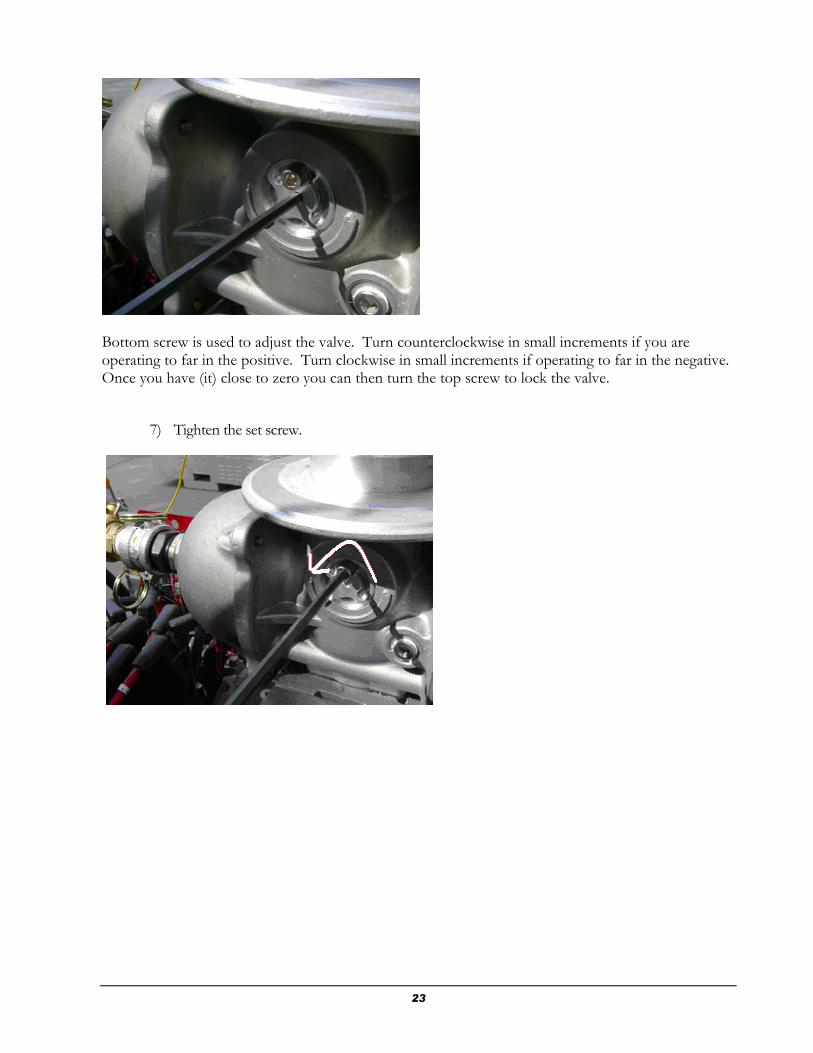
Bottom screw is used to adjust the valve. Turn counterclockwise in small increments if you are operating to far in the positive. Turn clockwise in small increments if operating to far in the negative. Once you have (it) close to zero you can then turn the top screw to lock the valve.
7) Tighten the set screw.

24
EGC Valve Viewer A/F Software Overview
EGC Valve Viewer A/F is a Microsoft Windows based application used for interfacing the EGC Air/Fuel Ratio Control System. EGC Valve Viewer A/F application provides real time monitoring of control functions in EGC, gives the user overall control over the EGC functionality, serves as diagnostic tool helping to detect, and evaluate problems related to fuel control and emissions reduction on natural gas engines. EGC Valve Viewer A/F is an intuitive, user-friendly software tool which offers an advanced array of features like easy setup of all user-definable set-points in the EGC, monitoring key data points, optional data logging, playback of history files, settings report, zoom feature, digital inputs control, and other.

25
Communication Setup
Communication Port Communication Port Properties Main Menu -> Comm Setup EGC Valve Viewer A/F automatically establishes communications with EGC using default communication port COM 1 and Device ID 1. However, it is possible to specify different communication port and/or device id. Communication setup guide:
1. Go to Comm Setup -> Comm Port 2. Communication Port dialog box should open up. 3. Enter communication port number and device id. 4. Press OK to apply changes. Communication Port Properties dialog box will open up
automatically. Do not change any settings! Press OK to close the dialog box.
EGC Valve Viewer A/F will apply new settings to establish communications with the EGC.

26
Default communication port settings:
Bits per second: 9600
Data bits: 8
Parity: None
Stop bits: 1
Flow control: None

27
Valve Settings Pressure Settings (Shortcut F2) Main Menu -> Valve Settings -> Pressure Settings Allows the user to modify EGC pressure settings, and save them for the next power cycle.
28
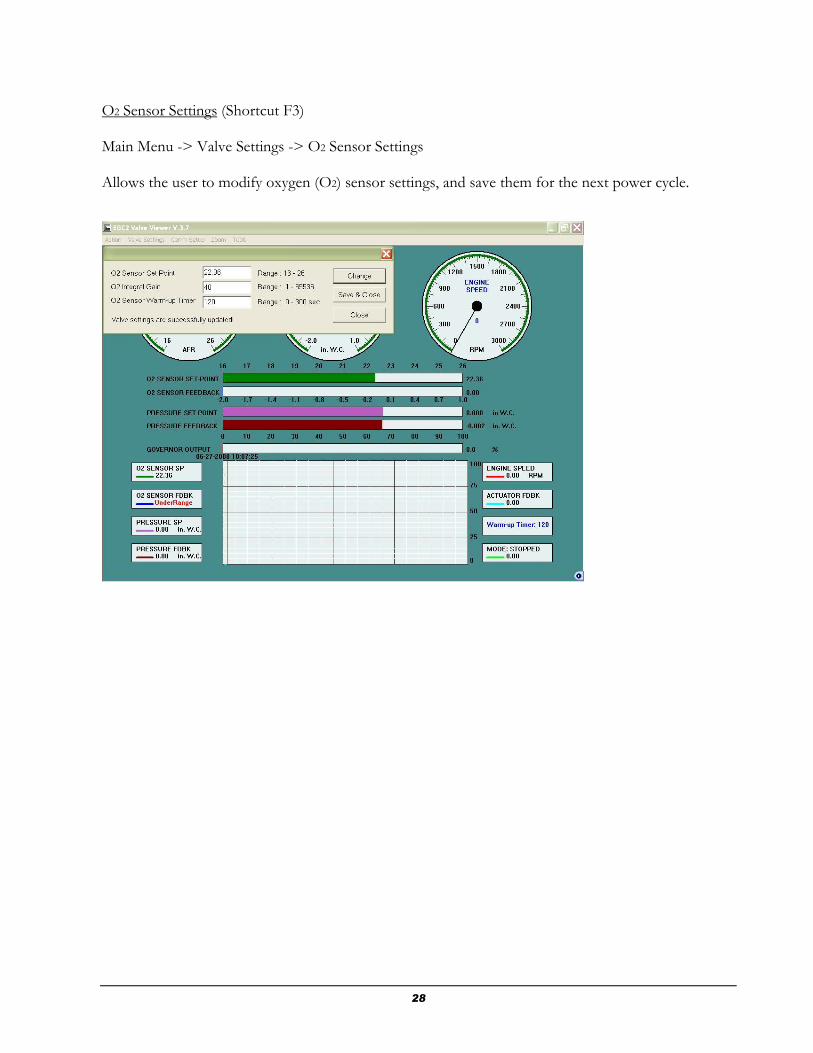
O2 Sensor Settings (Shortcut F3) Main Menu -> Valve Settings -> O2 Sensor Settings Allows the user to modify oxygen (O2) sensor settings, and save them for the next power cycle.

29
Governor Settings (Shortcut F4) Main Menu -> Valve Settings -> Governor Settings This option is available only for EGC governor units. Use it for quick access to the governor settings.

30
Governor Settings Description
Speed Set-point – The target value that the governor will aim to reach (for reference only). The speed set point is adjusted by the increase/decrease inputs on the carburetor (see wiring). The governor setpoint can also be set to operate at a single speed. Speed Proportional Gain- The number that is used as the starting value for the proportional gain in the GOV’s PID speed control loop. This value will vary from engine to engine. You can use the factory default values as a starting point. Speed Integral Gain- The number that will be used as a starting value for the integral in the GOV’s speed control loop. This value will vary from engine to engine. Idle Delay Timer- The time the engine is held at the idle speed before accelerating. Overspeed- The operator adjustable set point for the shutdown of the engine based upon RPM. In the engine RPM exceeds this set point; the governor will shut and remain closed until the start sequence is reinitiated. The control interface display will exhibit the message “OVERSPEED”. This message will be displayed until the engine reaches a complete stop and the operator presses any button on the interface or the engine is restarted. THIS FEATURE SHOULD NOT BE USED AS THE PRIMARY OVERSPEED SHUTDOWN! IT IS MEANT AS A REDUNDANT SHUTDOWN DEVICE. Speed (max) - The maximum normal operating speed in the engine. The GOV will not allow the speed set point to be set less then min speed. Do not set above 2100 RPM. Speed (min) - The minimum normal operating speed of the engine. Typically at the speed the engine runs when on resting on the idle adjust. The GOV will not allow the speed set point to be set greater then max speed. Ramp Rate- The set point that determines how fast the GOV will increase or decrease the speed setting. Ramp Rate is a number scale 1 to 100, 1 causing the fastest engine acceleration and 20 causing the slowest. Initially set Ramp Rate to a value of 30 and adjust as desired for maximum performance. Crank Speed- The speed that should be reached in order to open the carburetor. Typically, set to 100 rpm. Should always be set below the rpm of the engine when cranking on the starter alone. Idle Speed- The speed in order to reach 500rpm before it ramps up to min speed.

31
Calibrate Valve (Shortcut F5) Main Menu -> Valve Settings -> Calibrate Valve Password protected feature gives the user complete access to all the settings within EGC. Should you need to use this feature, please contact CCC Engineering Department to obtain the password. Tel: (858) 453-9880
Calibration guide:
1. Locate and select the setting that needs to be changed. 2. Its current value will be displayed in the edit box. 3. Type in new value, click Change button. 4. Press Save button to save the new settings, otherwise press Close button.

32

33
Upload Settings (Shortcut F6) This feature allows uploading and saving EGC settings into a data file (.dat), making it available for later access. Upload settings guide:
1. Go to Main Menu ->Valve Settings -> Upload Settings 2. Click Create File button to create and save new data file. 3. Press Upload Settings button. 4. Status message should notify you about the upload process details.
34
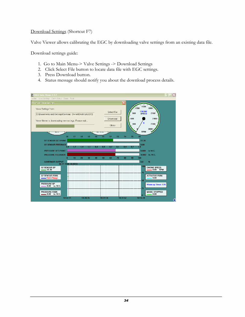
Download Settings (Shortcut F7) Valve Viewer allows calibrating the EGC by downloading valve settings from an existing data file. Download settings guide:
1. Go to Main Menu-> Valve Settings -> Download Settings 2. Click Select File button to locate data file with EGC settings. 3. Press Download button. 4. Status message should notify you about the download process details.
35
Action
Log File
Main Menu -> Action -> Log File
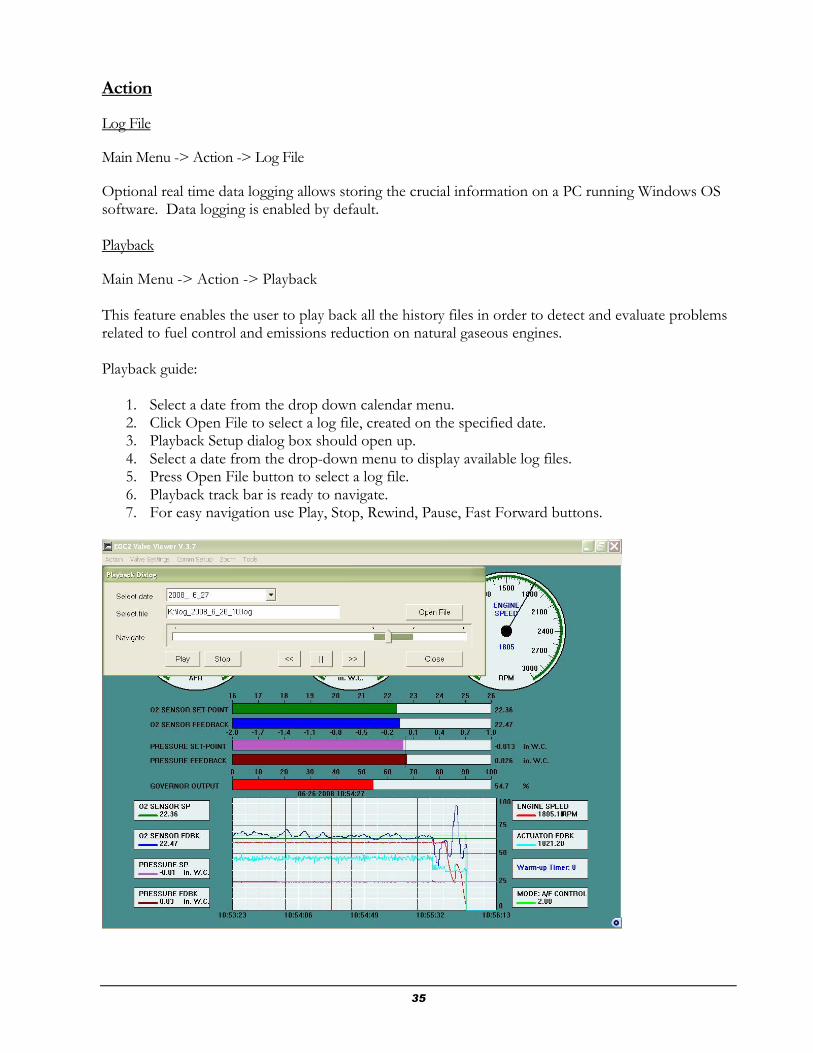
Optional real time data logging allows storing the crucial information on a PC running Windows OS software. Data logging is enabled by default. Playback
Main Menu -> Action -> Playback This feature enables the user to play back all the history files in order to detect and evaluate problems related to fuel control and emissions reduction on natural gaseous engines. Playback guide:
1. Select a date from the drop down calendar menu. 2. Click Open File to select a log file, created on the specified date. 3. Playback Setup dialog box should open up. 4. Select a date from the drop-down menu to display available log files. 5. Press Open File button to select a log file. 6. Playback track bar is ready to navigate. 7. For easy navigation use Play, Stop, Rewind, Pause, Fast Forward buttons.

36
Print Report Print EGC Traveler Report, containing current EGC settings. Main Menu -> Action -> Print Report Print Guide:
1. Enter EGC S/N, P/N, etc. 2. Click Print button and select Printer name. 3. Click OK to print the report.

37
Tools Feature Digital Inputs Attention:!! Engine must be stopped before proceeding.
Designed for testing purpose, this feature allows forcing On/Off/Release the following EGC inputs:
Ignition Confirm
Actuator Power
Force Actuator
Sensor Ignore
O2 Sensor Heater
Force O2 Sensor
Digital inputs control guide:
1. Go to Main menu -> Tools -> Digital Inputs. 2. Digital Inputs dialog box should open up. 3. Read-only grayed field contains currents digital input status. 4. Enter required digital input status in the edit box next to the read-only field,
click Change Status button. Change status as follows:
Force ON: 1
Force OFF: -1
Release: 0
5. Press Release All button to release all digital inputs.

38
O2 Sensor Cal
Attention!!: Engine must be shutdown before proceeding.
Main Menu -> Tools -> O2 Sensor Cal
This feature allows to perform free air calibration of the oxygen sensor directly from the Valve Viewer.
O2 sensor calibration guide:
1. Make sure the engine is stopped. 2. Press Free Air Cal button to initiate free air calibration. 3. Do not interrupt the calibration process. 4. The status of the free air calibration will be displayed in about 70 seconds.

39
Zoom Feature
Zoom In Choose this option to enlarge the view of the chart in order to see key data points in better resolution. Zoom Out Choose this option to switch back to normal view.

40
Troubleshooting EGC
Engine won’t start.
Ignition:
An engine will only run in compliance if in good working order. Ignition on all cylinders should be confirmed. Any damaged coils, or cracked spark plug wires should be replaced before installing the EGC. The spark plugs should be examined to verify that the gap is correct and they are not fowled. The battery must be in good condition, with a functioning alternator. While cranking the starter the battery voltage should remain above 7 volts.
Too rich:
The EGC is factory calibrated to provide the proper air to fuel ratio for starting, with 4 to 8 inches of supply pressure.
The two methods of leaning the mixture are:
1) Lower the default pressure setting using the Valve Viewer software.
2) Make the original position of the venturi adjustment then, turn the venturi adjustment in the clockwise direction.
If the engine is still too rich, remove the EGC actuator and check for debris in the fuel metering assembly. (Call CCC for instructions.)
Not enough Air - throttle body butterfly closed too far:
Adjust the min-stop or idle screw on the throttle body to open the butterfly enough to start the engine.
Too lean:
The EGC is factory calibrated to provide the proper air to fuel ratio for starting, with 4 to 8 inches of supply pressure.
The two methods of richening the mixture are:
3) Increasing the default pressure setting using the Valve Viewer software.
Chapter
6

41
4) Make the original position of the venturi adjustment then, turn the venturi adjustment in the counter-clockwise direction.
No fuel:
Check if the EGC has a blinking green status light when powered up. If not check the power connections.
When the engine is turning above {crank speed} which is typically 100 RPM, the EGC should switch from a blinking green light to blinking green and red. If the EGC is blinking green and read, it is emitting fuel at the right amount to start the engine.
If the EGC is blinking green and red but no fuel is reaching the engine, verify that there is 4 to 8 inches of water column supply to the EGC. Verify all shut off valves are open. It is possible to force the EGC to open for testing. (Contact CCC for instructions.)
Engine starts but over speeds or over shoots in speed. - throttle body
butterfly too far open:
Adjust the min-stop or idle screw on the throttle body to close the butterfly.
Engine fires but will not idle.
The idle speed set screw should be set so the engine start and will run at a minimum speed with the throttle closed against the stop.
Engine idles but won’t accelerate.
Check the connection to the throttle body or the actuator. Using the Valve Viewer software you can verify the operation of the governor actuator by using the force command. (Do this only when the engine is stopped)
The engine speed must reach the idle speed setting, and the idle timer expired before the EGC attempts to accelerate the engine.
Engine idles but after a moment dies.
Engines can not run (very well) in lean burn mode at idle speed. The EGC will stay in default mode (keeping the mixture richer) until the warm up timer expires. The engine will remain at Idle speed until the Idle timer expires. The warm up timer should always be longer than the Idle timer. The engine should be running at speed before the ECG2 switches to air to fuel ratio.
The engine maybe dieing when the EGC switches to air to fuel ration mode.
When the EGC is running in default mode the status led will blink green/red.
When the EGC , is controlling on air to fuel ratio, the status light will start blinking green.

42
Engine oscillates or hunts.
If the engine is unloaded or running at idle the engine is idling while too lean.
If running engine is oscillating when the engine is running at low speed reduce the min speed gains.
If the engine is running at max speed reduce the max speed gains.
Engine will not reach maximum load.
Verify the supply pressure is between 4 and 8 inches of water column while under load. Note that larger engines will require higher supply pressures. Engines running rich will require more supply pressure that ones running lean. Make sure you do not have the venturi adjusted closed.
Engines will not carry as much load while in running lean. The amount the engine is “de-rated” will vary from engine to engine.
No oxygen sensor reading.
Make sure your battery voltage is above 12volts while running.
The O2 sensor may have failed.
The O2 sensor will not read until the warm-up timer has expired.
Oxygen sensor reading unstable.
This can be caused by
1) Cold or failing o2 sensor.
2) Misfire, poor ignition or running too lean.
3) Sticky valves in the engine.
4) Exhaust leak.
5) Running the o2 sensor cable too close to the ignition system..
Gauge won’t light up.
Three dashes across the gauge is the normal condition when the unit is powered but not running, or running while in warm up mode.
Verify you have above battery voltage 10vdc.
Check the cable to the valve.
The gauge should be located no more than 20 feet from the valve.

43
Error message on the gauge.
E1 O2 sensor heater shorted, Replace o2 sensor.
E2 O2 sensor heater disconnected or open. Check connection, or replace o2 sensor. E3 Battery voltage too low for o2 sensor to function. Check or replace battery and/or charging system. E4 Free air calibration timed out. Replace O2 sensor. E5 Free air cal failed. Replace o2 sensor. E6 Battery voltage low warning Check or replace battery and/or charging system. E7 O2 Reading out of range. Perform a (Free air calibration). Note: whenever replacing an O2 sensor, a free air calibration must be done.

44
Product Warranty
ontinental Controls Corporation warrants that all goods furnished by CCC are free from
defects in workmanship and material as of the time and place of delivery.
As a matter of general warranty policy, CCC honors an original buyer's warranty claim in the event of
failure within 12 months of shipment to the end-user, when the equipment has been installed and
operated under normal conditions and in accordance with installation instructions contained in the
operating manual and generally accepted operating practices.
All warranty work must be performed and CCC’s manufacturing facility in San Diego. The customer
is responsible for shipment or delivery of the product to the CCC facility. CCC will pay return
ground freight. The customer will pay any expedited freight fees.
Chapter
7 C

45
Appendix A: EGC Envelope Drawing
Chapter
8

46
Appendix B: EGC Connector Locations

47
APPENDIX C
EGC with Flow Vectors

48
Appendix D: Wiring Diagram

49
(Blank Page)

50
Appendix F
List of recommended Actuators
Governors America Corp. P/N: ATB552T2N-12
Woodward Model Number: 0250P- 12A2LSF P/N: 8250-1017

51
Appendix: G
CARBURETOR SPECIFICATIONS
Electrical: Power Via connector J2
Input Voltage 10 to 15 VDC
Input Current (without Governor)
5 amps Nominal. 8 amps Peak
Input Current (Governor) 8 amps Nominal. 12 amps Peak
Weight 14 lbs
Communications RS 232 Via J6 9600 baud 8 bit no parity
Max Flow 40 scfm natural gas @8” W.C supply
Operating Temperature -40 to + 85 C
Altitude Limited by horse power demand on engine. (no operational limit)
Response Time 10% load to 90% load within 150ms
Mounting and Connectors Mounts on flange for IMPCO 200 Carburetor
Fuel Inlet ¾ Female NPT