Embed Size (px)
Citation preview

ELECTRONIC
ELECTRIC DRYER
For questions about features, operation/performance, parts,accessories or service, call: 1-800-253-1301
or visit our website at... www.whidpooLcom
Table of Contents ................................................ 2
W10110850A

TABLEOF CONTENTSDRYER SAFETY .............................................................................. 3
INSTALLATION INSTRUCTIONS .................................................. 4Tools and Parts ............................................................................ 4
Options ......................................................................................... 4Location Requirements ............................................................... 5Electrical Requirements ............................................................... 7Electrical Connection ................................................................... 9Venting Requirements ................................................................ 14Plan Vent System ....................................................................... 15Install Vent System ..................................................................... 16Install Leveling Legs ................................................................... 16Connect Vent .............................................................................. 17
Level Dryer ................................................................................. 17Complete Installation ................................................................. 17
DRYER USE .................................................................................. 18Starting Your Dryer ..................................................................... 18
Stopping Your Dryer ................................................................... 19Pausing or Restarting ................................................................. 19Control Locked ........................................................................... 19
Drying and Cycle Tips ................................................................ 19Status Lights ............................................................................... 20
Cycles ......................................................................................... 20Additional Features .................................................................... 21
Changing Cycles, Options and Modifiers .................................. 22Drying Rack ................................................................................ 22
DRYER CARE ................................................................................ 23
Cleaning the Dryer Location ....................................................... 23Cleaning the Lint Screen ............................................................ 23Cleaning the Dryer Interior ......................................................... 24Removing Accumulated Lint ...................................................... 24Vacation and Moving Care ......................................................... 24Changing the Drum Light ........................................................... 24
TROUBLESHOOTING .................................................................. 25
Dryer Operation .......................................................................... 25
Dryer Results .............................................................................. 25ASSISTANCE OR SERVICE ......................................................... 27
WARRANTY .................................................................................. 28

DRYERSAFETY
Your safety and the safety of others are very important.We have provided many important safety messages in this manual and on your appliance. Always read and obey all safety
messages.
This is the safety alert symbol.
This symbol alerts you to potential hazards that can kill or hurt you and others.
All safety messages will follow the safety alert symbol and either the word "DANGER" or "WARNING."These words mean:
You can be killed or seriously injured if you don't immediatelyfollow instructions.
You can be killed or seriously injured if you don't followinstructions.
All safety messages will tell you what the potential hazard is, tell you how to reduce the chance of injury, and tell you what can
happen if the instructions are not followed.
iMPORTANT SAFETY iNSTRUCTiONS
WARNING: To reduce the risk of fire, electric shock, or injury to persons when using the dryer, follow basic precautions,
including the following:
[] Read all instructions before using the dryer.
[] Do not place items exposed to cooking oils in your dryer.Items contaminated with cooking oils may contribute toa chemical reaction that could cause a load to catch fire.
[] Do not dry articles that have been previously cleaned in,washed in, soaked in, or spotted with gasoline, dry-cleaning solvents, or other flammable or explosivesubstances as they give off vapors that could ignite orexplode.
[] Do not allow children to play on or in the dryer. Closesupervision of children is necessary when the dryer isused near children.
[] Before the dryer is removed from service or discarded,remove the door to the drying compartment.
[] Do not reach into the dryer if the drum is moving.
[] Do not install or store the dryer where it will be exposedto the weather.
[] Do not tamper with controls.
[] Do not repair or replace any part of the dryer or attemptany servicing unless specifically recommended in thisUse and Care Guide or in published user-repairinstructions that you understand and have the skills tocarry out.
[] Do not use fabric softeners or products to eliminate staticunless recommended by the manufacturer of the fabricsoftener or product.
[] Do not use heat to dry articles containing foam rubber orsimilarly textured rubber-like materials.
[] Clean lint screen before or after each load.
[] Keep area around the exhaust opening and adjacentsurrounding areas free from the accumulation of lint, dust,and dirt.
[] The interior of the dryer and exhaust vent should becleaned periodically by qualified service personnel.
[] See installation instructions for grounding requirements.
SAVE TH ESE iNSTRUCTiONS
INSTALLATIONINSTRUCTIONS
Gather the required tools and parts before starting installation.Read and follow the instructions provided with any tools listedhere.
• Flat-blade screwdriver • Vent clamps
• #2 Phillips screwdriver • Caulking gun andcompound (for installing
• Adjustable wrench thatopens to 1" (2.5 cm) or new exhaust vent)hex-head socket wrench • Tin snips (new vent(for adjusting dryer feet) installations)
• Wire stripper (direct wire • 1/4"nut driverinstallations) (recommended)
• Level • Tape measure
Parts supplied
Remove parts packages from dryer drum. Check that all parts areincluded.
• Pa_s package
4 Leveling legs
NOTE: Do not use leveling legs if installing the dryer on apedestal.
Parts needed
Check local codes. Check existing electrical supply and venting.See "Electrical Requirements" and "Venting Requirements"before purchasing parts.
• For close-clearance installations between 31.5" (80.01 cm)and 37" (93.98 cm), see "Plan Vent System" section forventing requirements.
I_- 37" --_1(93.98 cm)
Mobile home installations require metal exhaust system hardwareavailable for purchase from the dealer from whom you purchasedyour dryer. For further information, please refer to the "Assistanceor Service" section of this manual.
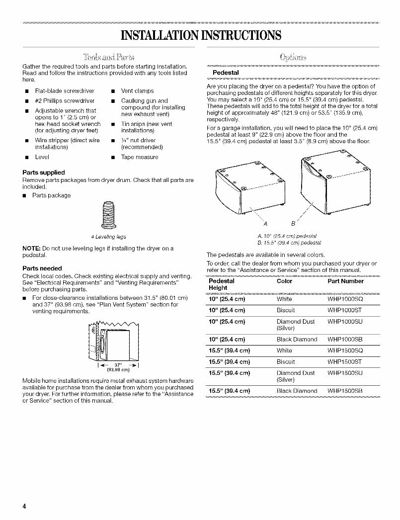
Pedestal
Are you placing the dryer on a pedestal? You have the option ofpurchasing pedestals of different heights separately for this dryer.You may select a 10" (25.4 cm) or 15.5" (39.4 cm) pedestal.These pedestals will add to the total height of the dryer for a totalheight of approximately 48" (121.9 cm) or 53.5" (135.9 cm),respectively.
For a garage installation, you will need to place the 10" (25.4 cm)pedestal at least 9" (22.9 cm) above the floor and the15.5" (39.4 cm) pedestal at least 3.5" (8.9 cm) above the floor.
A B
A. 10" (25.4 cm) pedestalB. 15.5" (39.4 cm) pedestal
The pedestals are available in several colors.
To order, call the dealer from whom you purchased your dryer orrefer to the "Assistance or Service" section of this manual.
Pedestal Color Part Number
Height
10" (25.4 cm) White WHP1000SC
10" (25.4 cm) Biscuit WHP1000ST
10" (25.4 cm) Diamond Dust WHP1000SU(Silver)
10" (25.4 cm) Black Diamond WHP1000SB
15.5" (39.4 cm) White WHP1500SC
15.5" (39.4 cm) Biscuit WHP1500ST
15.5" (39.4 cm) Diamond Dust WHP1500SU(Silver)
15.5" (39.4 cm) Black Diamond WHP1500SB
Stack Kit
Are you planning to stack your DUET ®washer and dryer? To doso, you will need to purchase a Stack Kit.
To order, call the dealer from whom you purchased your dryer orrefer to the "Assistance or Service" section of this manual. Askfor Part Number 8541503.
Door Reversal Kit
Are you planning to reverse the door swing direction on yourDUET®dryer? To do so, you will need to purchase a DoorReversal Kit.
To order, call the dealer from whom you purchased your dryer orrefer to the "Assistance or Service" section of this manual. Askfor Part Number 8579666.
Door Reversal and Stack Combination Kit
Are you planning to reverse the door swing direction on your® ®
DUET dryer and stack your DUET washer and dryer? To do so,you can purchase a Door Reversal and Stack Combination Kit.
To order, call the dealer from whom you purchased your dryer orrefer to the "Assistance or Service" section of this manual. Askfor Part Number W10110889.
Backguard
If you are installing your DUET ° washer and dryer and wish toavoid having loose items fall behind your machines, you maypurchase a pair of washer/dryer backguards. These will reducethe chance of items falling behind the machines during operation.
To order, call the dealer from whom you purchased your dryer orrefer to the "Assistance or Service" section of this manual. Askfor Part Number 8558694 (White).
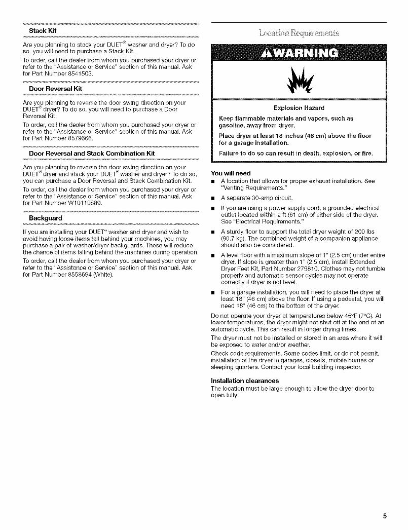
Explosion Hazard
Keep flammable materials and vapors, such asgasoline, away from dryer.
Place dryer at least 18 inches (46 cm) above the floorfor a garage installation.
Failure to do so can result in death, explosion, or fire.
You will need
• A location that allows for proper exhaust installation. See"Venting Requirements."
• Aseparate 30-amp circuit.
• If you are using a power supply cord, a grounded electricaloutlet located within 2 ft (61 cm) of either side of the dryer.See "Electrical Requirements."
• A sturdy floor to support the total dryer weight of 200 Ibs(90.7 kg). The combined weight of a companion applianceshould also be considered.
A level floor with a maximum slope of 1" (2.5 cm) under entiredryer. If slope is greater than 1" (2.5 cm), install ExtendedDryer Feet Kit, Part Number 279810. Clothes may not tumbleproperly and automatic sensor cycles may not operatecorrectly if dryer is not level.
• For a garage installation, you will need to place the dryer atleast 18" (46 cm) above the floor. If using a pedestal, you willneed 18" (46 cm) to the bottom of the dryer.
Do not operate your dryer at temperatures below 45°F (7°C). Atlower temperatures, the dryer might not shut off at the end of anautomatic cycle. This can result in longer drying times.
The dryer must not be installed or stored in an area where it willbe exposed to water and/or weather.
Check code requirements. Some codes limit, or do not permit,installation of the dryer in garages, closets, mobile homes orsleeping quarters. Contact your local building inspector.
Installation clearances
The location must be large enough to allow the dryer door toopen fully.

Dryer Dimensions
t
38,,/
(86.82cm)
51V2"
(130.81cm)
*Most installations require a minimum 5" (12.7 cm) clearancebehind the dryer for the exhaust vent with elbow. See "VentingRequirements."
Installation spacing for recessed area or closet installationThe following spacing dimensions are recommended for thisdryer. This dryer has been tested for spacing of 0" (0 cm)clearance on the sides and rear. Recommended spacing shouldbe considered for the following reasons:
• Additional spacing should be considered for ease ofinstallation and servicing.
• Additional clearances might be required for wall, door andfloor moldings.
• Additional spacing should be considered on all sides of thedryer to reduce noise transfer.
For closet installation, with a door, minimum ventilationopenings in the top and bottom of the door are required.Louvered doors with equivalent ventilation openings areacceptable.
• Companion appliance spacing should also be considered.
Custom undercounter installation - Dryer only
8" _,_o_ All tit Ill / \ lit tt_l
(96.52 cm
1"* _ _-._27"--_ _- 1"*2.8 cm i (68.6 cm 2.8 cm
*Required spacing
Closet installation - Dryer only
24 in,2.
(185 crn2)
I1"'1- 31,J,"_'-Is"**l(2.5cm) (6Ocm) {12.7cm)
A
A. Side view - closet or confined areaB. Closet door with vents
*Required spacing
**For side or bottom venting, 0" (0 cm) spacing is allowed.
Recessed or closet installation - Dryer on pedestal
olo
1"- t 1--27"--HI -1 ''(2.5 cm) (68.6 cm)
B -!4,.I1,mo ,H
i"'1 I_-- 31w'--_18"**1(2.5 crn) (2.5crn) (80 cm) (12.7crn)
A B
A. Recessed areaB. Side view - closet or confined area
*Required spacing
**For side or bottom venting, 0" (0 cm) spacing is allowed.
Recommended installation spacing for cabinetinstallation
• For cabinet installation, with a door, minimum ventilationopenings in the top of the cabinet are required.
7"* (17.8cm) 7"*(17.8 cm)
8"** 31W' 1"*(12.7 cm) (80.0 cra) (2.5 cra) (2.8 cm)(68.6 cm) (2.5 cra)
1" 27" 1"
*Required spacing
**For side or bottom venting, 0" (0 cm) spacing is allowed.
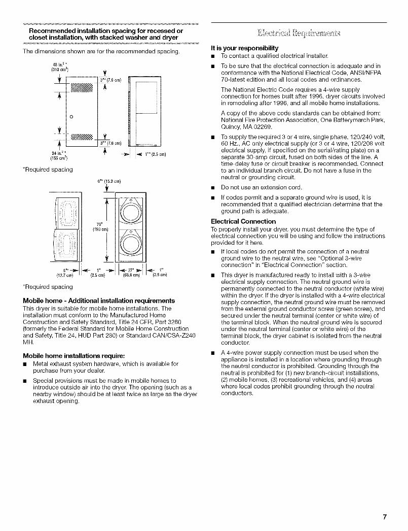
Recommended installation spacing for recessed orcloset installation, with stacked washer and dryer
The dimensions shown are for the recommended spacing.
48 in. 2 *
(310 ¢m2)
T]NN -
o
±__ __
24 irt.2 *
(155cm2)
*Required spacing
i',IS
Ji i_ ! !_i'_
5"* -_"{12.7crn)
.6crn)i
!3"* (7.6 cm)
l ....
76"
{193 cm)
" --_ _ 27"_1_(2.51cm) 68.6 cm
*Required spacing
1"*(2.5cm)
Mobile home - Additional installation requirementsThis dryer is suitable for mobile home installations. Theinstallation must conform to the Manufactured HomeConstruction and Safety Standard, Title 24 CFR, Part 3280(formerly the Federal Standard for Mobile Home Constructionand Safety, Title 24, HUD Part 280) or Standard CAN/CSA-Z240MH.
Mobile home installations require:• Metal exhaust system hardware, which is available for
purchase from your dealer.
Special provisions must be made in mobile homes tointroduce outside air into the dryer. The opening (such as anearby window) should be at least twice as large as the dryerexhaust opening.
It is your responsibility• To contact a qualified electrical installer.
• To be sure that the electrical connection is adequate and inconformance with the National Electrical Code, ANSI/NFPA70-latest edition and all local codes and ordinances.
The National Electric Code requires a 4-wire supplyconnection for homes built after 1996, dryer circuits involvedin remodeling after 1996, and all mobile home installations.
A copy of the above code standards can be obtained from:National Fire Protection Association, One Batterymarch Park,Quincy, MA 02269.
To supply the required 3 or 4 wire, single phase, 120/240 volt,60 Hz., AC only electrical supply (or 3 or 4 wire, 120/208 voltelectrical supply, if specified on the serial/rating plate) on aseparate 30-amp circuit, fused on both sides of the line. Atime-delay fuse or circuit breaker is recommended. Connectto an individual branch circuit. Do not have a fuse in theneutral or grounding circuit.
• Do not use an extension cord.
• If codes permit and a separate ground wire is used, it isrecommended that a qualified electrician determine that theground path is adequate.
Electrical Connection
To properly install your dryer, you must determine the type ofelectrical connection you will be using and follow the instructionsprovided for it here.
• If local codes do not permit the connection of a neutralground wire to the neutral wire, see "Optional 3-wireconnection" in "Electrical Connection" section.
This dryer is manufactured ready to install with a 3-wireelectrical supply connection. The neutral ground wire ispermanently connected to the neutral conductor (white wire)within the dryer. If the dryer is installed with a 4-wire electricalsupply connection, the neutral ground wire must be removedfrom the external ground conductor screw (green screw), andsecured under the neutral terminal (center or white wire) ofthe terminal block. When the neutral ground wire is securedunder the neutral terminal (center or white wire) of theterminal block, the dryer cabinet is isolated from the neutralconductor.
A 4-wire power supply connection must be used when theappliance is installed in a location where grounding throughthe neutral conductor is prohibited. Grounding through theneutral is prohibited for (1) new branch-circuit installations,(2) mobile homes, (3) recreational vehicles, and (4) areaswhere local codes prohibit grounding through the neutralconductors.

Ifusingapowersupplycord:UseaULlistedpowersupplycordkitmarkedforusewithclothesdryers.Thekitshouldcontain:[] AULlisted30-amppowersupplycord,rated
120/240voltminimum.ThecordshouldbetypeSRDorSRDTandbeatleast4ft (1.22m)long.Thewiresthatconnecttothedryermustendinringterminalsorspadeterminalswithupturnedends.
[] AULlistedstrainrelief.If your outlet looks like this:
4-wire receptacle (14-30R)
Then choose a 4-wire power supply cord with ring or spadeterminals and UL listed strain relief. The 4-wire power supplycord, at least 4 ft (1.22 m) long, must have four 10-gauge copperwires and match a 4-wire receptacle of NEMA Type 14-30R. Theground wire (ground conductor) may be either green or bare. Theneutral conductor must be identified by a white cover.
If your outlet looks like this:
3-wire receptacle (10-30R)
Then choose a 3-wire power supply cord with ring or spadeterminals and UL listed strain relief. The 3-wire power supplycord, at least 4 ft (1.22 m) long, must have three 10-gauge copperwires and match a 3-wire receptacle of NEMA Type 10-30R.
If connecting by direct wire:
Power supply cable must match power supply (4-wire or 3-wire)and be:
[] Flexible armored cable or nonmetallic sheathed copper cable(with ground wire), protected with flexible metallic conduit. Allcurrent-carrying wires must be insulated.
[] 10-gauge solid copper wire (do not use aluminum).
[] At least 5 ft (1.52 m) long.
GROUNDING INSTRUCTIONS
[] For a grounded, cord-connected dryer:This dryer must be grounded. In the event of malfunction orbreakdown, grounding will reduce the risk of electric shockby providing a path of least resistance for electric current.This dryer uses a cord having an equipment-groundingconductor and a grounding plug. The plug must be pluggedinto an appropriate outlet that is properly installed andgrounded in accordance with all local codes and ordinances.
[] For a permanently connected dryer:This dryer must be connected to a grounded metal,permanent wiring system, or an equipment-groundingconductor must be run with the circuit conductors and
connected to the equipment-grounding terminal or lead onthe dryer.
WARNING: Improper connection of the equipment-
grounding conductor can result in a risk of electric shock.Check with a qualified electrician or service representativeor personnel if you are in doubt as to whether the dryer isproperly grounded. Do not modify the plug on the powersupply cord: if it will not fit the outlet, have a proper outletinstalled by a qualified electrician.
SAVE THESE INSTRUCTIONS

Power Supply Cord
Fire Hazard
Use a new UL listed 30 amp power supply cord.
Use a UL listed strain relief.
Disconnect power before making electrical connections.
Connect neutral wire (white or center wire) to centerterminal (silver).
Ground wire (green or bare wire) must be connected togreen ground connector.
Connect remaining 2 supply wires to remaining2 terminals (gold).
Securely tighten all electrical connections.
Failure to do so can result in death, fire, orelectrical shock.
Direct Wire
Fire Hazard
Use 10 gauge solid copper wire.
Use a UL listed strain relief.
Disconnect power before making electrical connections.
Connect neutral wire (white or center wire) to centerterminal (silver).
Ground wire (green or bare wire) must be connected togreen ground connector.
Connect remaining 2 supply wires to remaining2 terminals (gold).
Securely tighten all electrical connections.
Failure to do so can result in death, fire, orelectrical shock.
1. Disconnect power.
2. Remove the hold-down screw and terminal block cover.
D
B
A. Neutral ground wireB. External ground conductor screwC. Center, silver-colored terminal block screwD. Terminal block cover and hold-down screw
3. Install strain relief.
Style 1: Power supply cord strain relief
Remove the screws from a 3/4"(1.9 cm) UL listed strainrelief (UL marking on strain relief). Put the tabs of the twoclamp sections into the hole below the terminal blockopening so that one tab is pointing up and the other ispointing down, and hold in place. Tighten strain reliefscrews just enough to hold the two clamp sectionstogether.
i ...........................C
A. Strain relief tab pointing upB. Hole below terminal block openingC. Clamp sectionD. Strain relief tab pointing down

Put power supply cord through the strain relief. Be surethat the wire insulation on the power supply cord is insidethe strain relief. The strain relief should have a tight fit withthe dryer cabinet and be in a horizontal position. Do notfurther tighten strain relief screws at this point.
Style 2: Direct wire strain relief
Unscrew the removable conduit connector and anyscrews from a %" (1.9 cm) UL listed strain relief (ULmarking on strain relief). Put the threaded section of thestrain relief through the hole below the terminal blockopening. Reaching inside the terminal block opening,screw the removable conduit connector onto the strainrelief threads•
A. Removable conduit connector
B• Hole below terminal block openingC. Strain relief threads
Put direct wire cable through the strain relief. The strainrelief should have a tight fit with the dryer cabinet and bein a horizontal position. Tighten strain relief screw againstthe direct wire cable.
Now complete installation following instructions for your typeof electrical connection:
4-wire (recommended)
3-wire (if 4-wire is not available)
Electrical Connection Options
If your home has: And you will be Go to Sectionconnecting to:
4-wire receptacle A UL listed, 120/ 4-wire connection:(NEMA Type 14-30R) 240-volt Power supply cord
minimum,
30-amp, dryerpower supplycord*
4-wire direct A fused 4-wire connection:disconnect or Direct Wire
circuit breakerbox*(12.7 cm)
3-wire receptacle A UL listed, 120/(NEMA type 10-30R) 240-volt
minimum,
30-amp, dryerpower supplycord*
3-wire connection:Power supply cord
3-wire direct A fused 3-wire connection:disconnect or Direct Wire
circuit breakerbox*
*If local codes do not permit the connection of a cabinet-groundconductor to the neutral wire, go to "Optional 3-wireconnection" section.
4-wire connection: Power supply cord
IMPORTANT: A 4-wire connection is required for mobile homesand where local codes do not permit the use of 3-wireconnections.
B F
C D E G
A. 4-wire receptacle (NEMA type 14-30R)B. 4-prong plugC. Ground prongD. Neutral prongE. Spade terminals with upturned endsF. 3_,, (1.9 cm) UL listed strain reliefG. Ring terminals
1. Remove center silver-colored terminal block screw.
10

2,
3,
4,
Remove neutral ground wire from external ground conductorscrew. Connect neutral ground wire and the neutral wire(white or center wire) of power supply cord under center,silver-colored terminal block screw. Tighten screw.
A \ _ _Jl_L_li_
J.....................................................................E
A, External ground conductor screw - Dotted line showsposition of NEUTRAL ground wire before being moved tocenter silver-colored terminal block screw.
B. Center silver-colored terminal block screw
C. Neutral ground wireD, Neutral wire (white or center wire)E. _/4"(1,9 cm) UL listed strain relief
Connect ground wire (green or bare) of power supply cord toexternal ground conductor screw. Tighten screw.
A _-._ _ .........................D
B _(_ -'_-_:: __.,2 E
A. External ground conductor screwB. Ground wire (green or bare) of power supply cordC, _" (1.9 cm) UL listed strain reliefD, Center silver-colored terminal block screw
E. Neutral ground wireE Neutral wire (white or center wire)
Connect the other wires to outer terminal block screws.Tighten screws.
I I
5, Tighten strain relief screws.
6. Insert tab of terminal block cover into slot of dryer rear panel.Secure cover with hold-down screw.
7, You have completed your electrical connection. Now go to"Venting Requirements."
4-wire connection: Direct wire
IMPORTANT: A 4-wire connection is required for mobile homesand where local codes do not permit the use of 3-wireconnections.
Direct wire cable must have 5 ft (1.52 m) of extra length so dryercan be moved if needed.
Strip 5" (12.7 cm) of outer covering from end of cable, leavingbare ground wire at 5" (12.7 cm). Cut 11/2'' (3.8 cm) from3 remaining wires. Strip insulation back 1" (2.5 cm). Shape endsof wires into a hook shape.
-v'
When connecting to the terminal block, place the hooked end ofthe wire under the screw of the terminal block (hook facing right),squeeze hooked end together and tighten screw, as shown.
1,
2.
Remove center silver-colored terminal block screw.
Remove neutral ground wire from external ground conductorscrew. Connect neutral ground wire and place the hookedend (hook facing right) of the neutral wire (white or centerwire) of direct wire cable under the center screw of theterminal block. Squeeze hooked ends together. Tightenscrew.
A. External ground conductor screw - Dotted line showsposition of NEUTRAL ground wire before being moved tocenter silver-colored terminal block screw.
B. Center silver-colored terminal block screw
C. Neutral ground wireD. Neutral wire (white or center wire)E, 3/4"(1.9 cm) UL listed strain relief
11

3. Connect ground wire (green or bare) of direct wire cable toexternal ground conductor screw. Tighten screw.
2. Connect neutral wire (white or center wire) of power supplycord to the center, silver-colored terminal screw of theterminal block. Tighten screw.
F
A. External ground conductor screwB. Ground wire (green or bare) of power supply cableC. 3/4"(1.9 cm) UL listed strain reliefD. Center silver-colored terminal block screw
E. Neutral ground wireF Neutral wire (white or center wire)
4. Place the hooked ends of the other direct wire cable wiresunder the outer terminal block screws (hooks facing right).Squeeze hooked ends together. Tighten screws.
!! !!
5. Tighten strain relief screw.
6. Insert tab of terminal block cover into slot of dryer rear panel.Secure cover with hold-down screw.
7. You have completed your electrical connection. Now go to"Venting Requirements."
3-wire connection: Power supply cord
Use where local codes permit connecting cabinet-groundconductor to neutral wire.
B
C
D E
A. 3-wire receptacle (NEMA type lO-30R)B. 3-wire plugC. Neutral prongD. Spade terminals with up turned endsE. _" (1.9 cm) UL listed strain reliefF. Ring terminals
G. Neutral (white or center wire)
1. Loosen or remove center silver-colored terminal block screw.
E
A. External ground conductor screwB. Neutral ground wireC. Center silver-colored terminal block screw
D. Neutral wire (white or center wire)E. _" (1.9 cm) UL Iisted strain relief
Connect the other wires to outer terminal block screws.Tighten screws.
!! !!
4. Tighten strain relief screws.
5. Insert tab of terminal block cover into slot of dryer rear panel.Secure cover with hold-down screw.
6. You have completed your electrical connection. Now go to"Venting Requirements."
3-wire connection: Direct wire
Use where local codes permit connecting cabinet-groundconductor to neutral wire.
Direct wire cable must have 5 ft (1.52 m) of extra length so dryercan be moved if needed.
Strip 31/2'' (8.9 cm) of outer covering from end of cable. Stripinsulation back 1" (2.5 cm). If using 3-wire cable with groundwire, cut bare wire even with outer covering. Shape ends of wiresinto a hook shape.
12

When connecting to the terminal block, place the hooked end ofthe wire under the screw of the terminal block (hook facing right),squeeze hooked end together and tighten screw, as shown.
1=
2.
Loosen or remove center silver-colored terminal block screw.
Place the hooked end of the neutral wire (white or center wire)of direct wire cable under the center screw of terminal block(hook facing right). Squeeze hooked end together. Tightenscrew.
3=
A. External ground conductor screwB. Neutral ground wireC. Center silver-colored terminal block screwD. Neutral wire (white or center wire)E. _" (1.9 cm) UL Iisted strain relief
Place the hooked ends of the other direct wire cable wiresunder the outer terminal block screws (hooks facing right).Squeeze hooked ends together. Tighten screws.
!! !!
4. Tighten strain relief screw.
5. Insert tab of terminal block cover into slot of dryer rear panel.Secure cover with hold-down screw.
6. You have completed your electrical connection. Now go to"Venting Requirements."
Optional 3-wire connection
Use for direct wire or power supply cord where local codesdo not permit connecting cabinet-ground conductor toneutral wire.
1. Remove center silver-colored terminal block screw.
2. Remove neutral ground wire from external ground conductorscrew. Connect neutral ground wire and the neutral wire(white or center wire) of power supply cord/cable undercenter, silver-colored terminal block screw. Tighten screw.
B
..............................._ _ ................... C
// IIIIIILI
A. External ground conductor screwB. Center silver-colored terminal block screw
C. Neutral ground wireD. Neutral wire (white or center wire)E, _" (1.9 cm) UL Iisted strain reliefE Grounding path determined by a qualified electrician
3. Connect the other wires to outer terminal block screws.Tighten screws.
!! !!
4. Tighten strain relief screws.
5. Connect a separate copper ground wire from the externalground conductor screw to an adequate ground.
6. Insert tab of terminal block cover into slot of dryer rear panel.Secure cover with hold-down screw.
13

Fire Hazard
Use a heavy metal vent.
Do not use a plastic vent.
Do not use a metal foil vent.
Failure to fellow these instructions can result in deathor fire.
WARNING: To reduce the risk of fire, this dryer MUST BEEXHAUSTED OUTDOORS.
IMPORTANT: Observe all governing codes and ordinances.
The dryer exhaust must not be connected into any gas vent,chimney, wall, ceiling or a concealed space of a building.
If using an existing vent system
• Clean lint from the entire length of the system and make sureexhaust hood is not plugged with lint.
• Replace any plastic or metal foil vent with rigid or flexibleheavy metal vent.
• Review Vent system chart. Modify existing vent system ifnecessary to achieve the best drying performance.
If this is a new vent system
Vent material
• Use a heavy metal vent. Do not use plastic or metal foil vent.
• 4" (10.2 cm) heavy metal exhaust vent and clamps must beused. DURASAFE TM venting products are recommended.
4" (10.2cm) heavymetal exhaust vent
DURASAFE TM vent products can be purchased from yourdealer or by calling Whirlpool Parts and Accessories. Formore information, see the "Assistance or Service" section ofthis manual.
Rigid metal vent
• For best drying performance, rigid metal vents arerecommended.
• Rigid metal vent is recommended to avoid crushing andkinking.
Flexible metal vent
• Flexible metal vents are acceptable only if accessible forcleaning.
• Flexible metal vent must be fully extended and supportedwhen the dryer is in its final location.
• Remove excess flexible metal vent to avoid sagging andkinking that may result in reduced airflow and poorperformance.
• Do not install flexible metal vent in enclosed walls, ceilings orfloors.
Elbows
45° elbows provide better airflow than 90° elbows.
Clamps
J9Good Better
Use clamps to seal all joints.
Exhaust vent must not be connected or secured with screwsor other fastening devices that extend into the interior of theduct. Do not use duct tape.
Clamp
Exhaust
Recommended hood styles are shown here.
B
(10.2 cm)
A. Louvered hood styleB. Box hood style
The angled hood style (shown here) is acceptable.4-"
(10.2 cm)__
v_.4,\ 21/2"(6.4- cm)
• An exhaust hood should cap the vent to keep rodents andinsects from entering the home.
• Exhaust hood must be at least 12" (30.5 cm) from the groundor any object that may be in the path of the exhaust (such asflowers, rocks or bushes, snow line, etc.).
• Do not use an exhaust hood with a magnetic latch.
improper venting can cause moisture and lint to collectindoors, which may result in:
[] Moisture damage to woodwork, furniture, paint, wallpaper,carpets, etc.
[] Housecleaning problems and health problems.
14

Choose your exhaust installation type
Recommended exhaust installations
Typical installations vent the dryer from the rear of the dryer.Other installations are possible.
B
A=--
............... F
...................................G
A B
A. Standard rear offset exhaust installation
B. Left or right side exhaust installationC. Bottom exhaust installation (not an option
with pedestal installations)
A. DryerB. ElbowC. WallD. Exhaust hood
E. ClampsF. Rigid metal or flexible metal vent
G. Vent length necessary to connect elbowsH. Exhaust outlet
Optional exhaust installationsThis dryer can be converted to exhaust out the right side, leftside, or through the bottom. Contact your local dealer to have thedryer converted.
Fire Hazard
Cover unused exhaust holes with one of the
following kits:
279818 (white)
279820 (black)
279925 (biscuit)
279989 (pewter)
280171 (diamond dust)
Contact your local dealer.
Failure to follow these instructions can result in death,fire, electrical shock, or serious injury.
Alternate installations for close clearances
Venting systems come in many varieties. Select the type best foryour installation. Two close-clearance installations are shown.Refer to the manufacturer's instructions.
.... 7,
XJ -
"ii
To=;:#
\
A B
A. Over-the-top installation (also available with oneoffset elbow)
B. Periscope installation
NOTE: The following kits for close clearance alternateinstallations are available for purchase. Please see the"Assistance or Service" section of this manual to order.
• Over-the-Top Installation:
Part Number 4396028
• Periscope Installation (For use with dryer vent to wall ventmismatch):
Part Number 4396037 - 0" (0 cm) to 18" (45.72 cm)mismatch
Part Number 4396011 - 18" (45.72 cm) to 29" (73.66 cm)mismatch
Part Number 4396014 - 29" (73.66 cm) to 50" (127 cm)mismatch
15

Special provisions for mobile home installationsThe exhaust vent must be securely fastened to a noncombustibleportion of the mobile home structure and must not terminatebeneath the mobile home. Terminate the exhaust vent outside.
Determine vent path
• Select the route that will provide the straightest and mostdirect path outdoors.
• Plan the installation to use the fewest number of elbows andturns.
• When using elbows or making turns, allow as much room aspossible.
• Bend vent gradually to avoid kinking.
• Use the fewest 90 ° turns possible.
Determine vent length and elbows needed for bestdrying performance
• Use the following Vent system chart to determine type of ventmaterial and hood combinations acceptable to use.
NOTE: Do not use vent runs longer than those specified inthe Vent system chart. Exhaust systems longer than thosespecified will:
• Shorten the life of the dryer.
• Reduce performance, resulting in longer drying times andincreased energy usage.
The Vent system chart provides venting requirements that willhelp to achieve the best drying performance.
Vent system chartNOTE: Side and bottom exhaust installations have a 90° turninside the dryer. To determine maximum exhaust length, add one90° turn to the chart.
Number of Type of Box or Angled90° turns vent Iouvered hoodsor elbows hoods
0 Rigid metal 64 ft (20 m) 58 ft (17.7 m)Flexible metal 36 ft (11 m) 28 ft (8.5 m)
1 Rigid metal 54 ft (16.5 m) 48 ft (14.6 m)Flexible metal 31 ft (9.4 m) 23 ft (7 m)
2 Rigid metal 44 ft (13.4 m) 38 ft (11.6 m)Flexible metal 27 ft (8.2 m) 19 ft (5.8 m)
3 Rigid metal 35 ft (10.7 m) 29 ft (8.8 m)Flexible metal 25 ft (7.6 m) 17 ft (5.2 m)
4 Rigid metal 27 ft (8.2 m) 21 ft (6.4 m)Flexible metal 23 ft (7 m) 15 ft (4.6 m)
1. Install exhaust hood. Use caulking compound to seal exteriorwall opening around exhaust hood.
2. Connect vent to exhaust hood. Vent must fit inside exhausthood. Secure vent to exhaust hood with 4" (10.2 cm) clamp.
3. Run vent to dryer location. Use the straightest path possible.See "Determine vent path" in "Plan Vent System." Avoid 90°turns. Use clamps to seal all joints. Do not use duct tape,screws or other fastening devices that extend into the interiorof the vent to secure vent.
Excessive Weight Hazard
Use two or more people to move and install dryer.
Failure to do so can result in back or other injury.
1. To protect the floor, use a large flat piece of cardboard fromthe dryer carton. Place cardboard under the entire back edgeof the dryer.
16
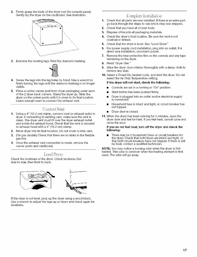
2. Firmly grasp the body of the dryer (not the console panel).Gently lay the dryer on the cardboard. See illustration.
3. Examine the leveling legs. Find the diamond marking.
-g4. Screw the legs into the leg holes by hand. Use a wrench to
finish turning the legs until the diamond marking is no longervisible.
5. Place a carton corner post from dryer packaging under eachof the 2 dryer back corners. Stand the dryer up. Slide thedryer on the corner posts until it is close to its final location.Leave enough room to connect the exhaust vent.
1. Using a 4" (10.2 cm) clamp, connect vent to exhaust outlet indryer. If connecting to existing vent, make sure the vent isclean. The dryer vent must fit over the dryer exhaust outletand inside the exhaust hood. Check that the vent is secured
to exhaust hood with a 4" (10.2 cm) clamp.
2. Move dryer into its final location. Do not crush or kink vent.
3. (On gas models) Check that there are no kinks in the flexiblegas line.
4. Once the exhaust vent connection is made, remove thecorner posts and cardboard.
Check the levelness of the dryer. Check levelness firstside to side, then front to back.
1. Check that all parts are now installed. If there is an extra part,go back through the steps to see which step was skipped.
2. Check that you have all of your tools.
3. Dispose of/recycle all packaging materials.
4. Check the dryer's final location. Be sure the vent is notcrushed or kinked.
5. Check that the dryer is level. See "Level Dryer."
6. For power supply cord installation, plug into an outlet. Fordirect wire installation, reconnect power.
7. Remove the blue protective film on the console and any taperemaining on the dryer.
8. Read "Dryer Use."
9. Wipe the dryer drum interior thoroughly with a damp cloth toremove any dust.
10. Select a Timed Dry heated cycle, and start the dryer. Do notselect the Air Only Temperature setting.
If the dryer will not start, check the following:
• Controls are set in a running or "On" position.
• Start button has been pushed firmly.
• Dryer is plugged into an outlet and/or electrical supplyis connected.
• Household fuse is intact and tight, or circuit breaker hasnot tripped.
• Dryer door is closed.
11. When the dryer has been running for 5 minutes, open thedryer door and feel for heat. If you feel heat, cancel cycle andclose the door.
If you do not feel heat, turn off the dryer and check thefollowing:
• There may be 2 household fuses or circuit breakers forthe dryer. Check that both fuses are intact and tight, orthat both circuit breakers have not tripped. If there is stillno heat, contact a qualified technician.
NOTE: You may notice a burning odor when the dryer is firstheated. This odor is common when the heating element is firstused. The odor will go away.
If the dryer is not level, prop up the dryer using a wood block.Use a wrench to adjust the legs up or down and check again forlevelness.
17
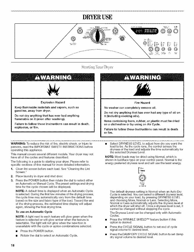
DRYERUSE
Explosion Hazard
Keep flammable materials and vapors, such asgasoline, away from dryer.
Do not dry anything that has ever had anythingflammable on it (even after washing).
Failure to follow these instructions can result in death,explosion, or fire.
Fire Hazard
No washer can completely remove oil.
Do not dry anything that has ever had any type of oil onit (including cooking oils),
Items containing foam, rubber, or plastic must be driedon a clothesline or by using an Air Cycle.
Failure to follow these instructions can result in deathor fire.
WARNING: To reduce the risk of fire, electric shock, or injury topersons, read the IMPORTANT SAFETY INSTRUCTIONS beforeoperating this appliance,
This manual covers several different models. Your dryer may nothave all of the cycles and features described.
The following is a guide to starting your dryer. Please refer tospecific sections of this manual for more detailed information.
1. Clean lint screen before each load, See "Cleaning the LintScreen."
2. Place laundry in dryer and shut door.3. Press the POWER button then rotate the dial to select either
an Automatic or Manual Cycle. The preset settings and dryingtime for the cycle chosen will be displayed.
NOTE: A default time is displayed when an Automatic Cycleis selected. During the first few minutes of the drying process,the cycle time may automatically vary from the default timebased on the size and fabric type of the load. Toward the endof the drying process, the estimated time display will adjustagain, showing the final drying time.
To use an Automatic Cycle
NOTE: A light next to each feature will glow green when thefeature is selected or will glow amber when the feature isselectable, The light will not glow when the selection isunavailable with the cycle or option combinations selected.
• Press the POWER button.
• Rotate the dial to select an Automatic Cycle.
• Select DRYNESS LEVEL to adjust how dry you want theload to be. As the cycle runs, the control senses thedryness of the load and adjusts the time automatically forthe selected Dryness Level.
NOTE: Most loads may be dried using Normal, which isshown in boldface type on your control panel. Normal is theenergy preferred dryness level and will use the least energy.
M0_e{ N0F_tlaU
Less
DrynessLevel
The default dryness setting is Normal when an Auto DryCycle is selected. You can select a different dryness level,depending on your load, by pressing DRYNESS LEVELand choosing More, Normal or Less. Selecting More,Normal or Less automatically adjusts the dryness level atwhich the dryer will shut off. Once a dryness level is set, itcannot be changed without stopping the cycle.
The Dryness Level can be changed only with AutomaticCycles.Press the WRINKLE SHIELD TM feature button if thisoption is desired.
Press the CYCLE SIGNAL button to set end of cyclesignal volume to desired level.
Press the DAMP DRY CYCLE SIGNAL button to set dampdry signal volume to desired level.
18

• Press and hold START button until dryer starts (about1 second).
Once an Automatic cycle has started, the WRINKLESHIELD TM feature and cycle signals can be adjusted. Pressthe PAUSE/CANCEL key twice to stop the dryer and clear thesettings, allowing you to select another cycle and DrynessLevel.
NOTE: Time and Temperature are not adjustable forAutomatic Cycles. Pressing the DRY TIME or TEMPERATUREbuttons will cause a triple beep, indicating that the timecannot be changed.
How Automatic Cycles Work
The AccelerCare TM function improves drying performancewith Auto Moisture Sensing Plus, which advances the cycleas moisture is extracted from clothing. A thermistor(electronic temperature sensor) and moisture sensing strips inthe dryer drum help measure the amount of moisture in theclothes as they tumble. An electronic control determines theload type to help save time, avoid overdrying, and increasethe accuracy of the end dryness level. After the first 5 minutesof an automatic cycle, the estimated time display will adjustbased on the approximate load size, cycle, dryness levelselected and amount of moisture left in the clothes. When theclothes have reached approximately 80% of the dryness levelselected, the estimated time display will adjust again,showing the final drying time. The AccelerCare TM featuretakes the guesswork out of drying time and enhances fabriccare.
To use a Manual Cycle
NOTE: A light next to each feature will glow green when thefeature is selected or will glow amber when the feature isselectable. The light will not glow when the selection isunavailable with the cycle or option combinations selected.
• Press POWER.
Rotate the dial to select a Manual Cycle.
Press the DRY TIME up or down buttons until the desireddrying time is displayed. Press DRY TIME, and the timewill change by 1-minute intervals. Press and hold DRYTIME, and the time will change by 5-minute intervals. Theinitial time displayed is the actual drying time.
Adi_stManual0ryTime
®®The Dry Time feature can be used only with ManualCycles.
Press TEMPERATURE until the desired temperatureglows green.
I High
Medium
Low
ExtraLowAir Only
TemperatureAdjst Manual
Cyde_Only
Temperature settings can be changed only with ManualCycles.Press the WRINKLE SHIELD TM feature button if thisoption is desired.
Press the CYCLE SIGNAL button to set end of cyclesignal volume to desired level.
• Press and hold START button until dryer starts (about1 second).
NOTE: Dryness Level is not adjustable for Manual Cycles.Pressing the Dryness Level button will cause the triple beepindicating that this option is not selectable.
While a Manual Cycle is running, you can change the settingsfor Time, Temperature, the WRINKLE SHIELD TM feature andthe cycle signals. Press the PAUSE/CANCEL key twice tostop the dryer and clear the settings, allowing you to selectanother cycle.
To stop your dryer at any timePress PAUSE/CANCELtwice or open the door.
To pause the dryer at any time
Open the door or press PAUSE/CANCEL once.
To restart the dryer
Close the door and press and hold START button until dryerstarts.
NOTE: Drying will continue from where the cycle was interrupted,if you close the door and press Start within 5 minutes. If the cycleis interrupted for more than 5 minutes, the dryer will shut off.Select new cycle settings before restarting the dryer.
This feature allows you to lock your settings to avoid unintendeduse of the dryer. You can also use the Control Locked feature toavoid unintended cycle or option changes during dryer operation.
To enable the Control Locked feature when dryer isrunning:Press and hold the CONTROL LOCK/UNLOCK button for3 seconds. The control is locked when a single beep is heard andthe Control Locked status light is on.
• When the dryer is off, it is not necessary to press the ControlOn button before activating the Control Locked feature.
To unlock:Press and hold the CONTROL LOCK/UNLOCK button for3 seconds to turn this feature off.
NOTE: When the dryer is running and Control Locked is on, thedryer can be stopped by pressing the Pause/Cancel button, butcannot be restarted until the control is unlocked.
Select the correct cycle and dryness level or temperature for yourload. If an Automatic Cycle is running, the display shows theestimated cycle time when your dryer is automatically sensingthe dryness level of your load. If a Manual Cycle is running, thedisplay shows the exact number of minutes remaining in thecycle.
Cool Down tumbles the load without heat during the last fewminutes of all cycles. Cool Down makes the loads easier tohandle and reduces wrinkling. The length of the Cool Downdepends on the load size and dryness level.
Drying tips• Follow care label directions when they are available.
• If desired, add a fabric softener sheet. Follow packageinstructions.
19

Remove the load from the dryer as soon as tumbling stops toreduce wrinkling. This is especially important for permanentpress, knits and synthetic fabrics•
Avoid drying heavy work clothes with lighter fabrics. Thiscould cause overdrying of lighter fabrics, leading to increasedshrinking or wrinkling.
If you dry sheets in a mixed load or large items in the BulkyItems cycle, rearrange the load when the signal sounds• Thiswill aid in the drying process.
Cycle tips• Dry most loads using the preset cycle settings.
• Refer to the Automatic or Manual Preset Cycle Settings chart(in the "Cycles" section) for a guide to drying various loads.
Drying temperature and Dryness Level are preset whenyou choose an Automatic Cycle. You can choose adifferent dryness level, depending on your load bypressing the DRYNESS LEVEL button to select MORE,NORMAL or LESS.
• If you wish to adjust the cycle length of a Manual Cycle,you must press the DRY TIME up or down buttons. Adjustthe temperature of a Manual Cycle by pressingTEMPERATURE until the desired temperature is selected.
NOTE: You cannot choose a Dryness Level with ManualCycles.
d'_f<
You may follow the progress of your dryer with the drying Statusindicator lights.
WrinkleShield Sensing
Wet Damp C001D0wnDone
WRINKLE SHIELD TM Feature
The WRINKLE SHIELD TM feature light glows during the WRINKLESHIELD TM feature (when selected)•
SensingWhen a cycle is first turned on, the Sensing light glows until a wetitem is detected.
• In an Automatic Cycle, if a wet item has not been detectedwithin 10 minutes, the Sensing light will turn off and the dryerwill shut down.
• In a Manual Cycle, if a wet item is not detected after10 minutes, the Wet light turns on and the selected cyclecontinues.
Wet
The Wet light will turn on when a wet item has been detected inthe dryer. The Wet light will remain on until:
• The damp dry point is reached in an Automatic Cycle.
• The dryer enters the cool down period in a Manual Cycle.
DampThe Damp light indicates that the load has reached the damp drylevel. To be alerted when your load is approximately 80% dry, youmay use the Damp Dry Cycle Signal option. See "Damp DryCycle Signal" in "Additional Features" section•
NOTE: The Damp light is not used with manual cycles.
Cool Down
The Cool Down light glows during the cool down part of thecycle. Laundry is cooling down for ease in handling.
Done
The Done light illuminates when the drying cycle is finished• Thisindicator stays on during the WRINKLE SHIELD TM feature.
Indicator lightsOther indicator lights on the control panel show Cycle,Temperature, Dryness Level, and cycle signal settings selected.
The time display will indicate the estimated or actual timeremaining in a cycle.
Select the drying cycle that matches the type of load you aredrying. See Automatic Preset or Manual Preset Cycle Settingschart.
NORMALCASUAL BULKYITEMS
DELICATE HEAVYDUTY
SUPERDELICATE
DAMPDRYAtJTOMATICCYCLI3 MANUALCYCLES
TIMEDDRY
TOUCHUP
IUICKDRY
Cycle Control knob
Automatic Cycles
Automatic Cycles allow you to match the cycle to the load youare drying. See the following Automatic Preset Cycle Settingschart. Each cycle dries certain fabrics at the recommendedtemperature. A sensor detects the moisture in the load andautomatically adjusts the drying time for optimal drying.
Heavy DutyUse this cycle to get High heat for heavyweight mixed loads,cotton towels or jeans•
Bulky ItemsUse this cycle to get Medium heat for drying large items thatrequire very long drying times such as jackets, comforters andpillows• Rearrange the load halfway through the dryer cycle. Thiswill aid in the drying process.
Normal
Use this cycle to get Medium heat for drying sturdy fabrics suchas work clothes and sheets.
Casual
Use this cycle to get Low heat for drying no-iron fabrics such assport shirts, casual business clothes and permanent pressblends.
Delicate
Use this cycle to get Low heat to gently dry items such aswashable knit fabrics.
Super DelicateUse this cycle to get Extra-Low heat to gently dry items such aslingerie.
20

Damp DryUse this cycle to dry items to a damp level using Low heat. Dampdry items such as jeans (to avoid stiffness) or cotton clothing (tomake ironing easier), The temperature setting on this cyclecannot be adjusted. Items will have different levels of dampness.At the end of this cycle, clothes will be damp. To be alerted whenthis cycle is complete, select the End of Cycle Signal.
Automatic Preset Cycle Settings
Automatic Cycles Temperature Time*Load Type (Minutes)
HEAVY DUTY High 50Heavyweight items, towels, jeans
BULKY ITEMS Medium 55Jackets, comforters, pillows
NORMAL Medium 40Corduroys, work clothes, sheets
CASUAL Low 35Permanent press, synthetics
DELICATE Low 30Lingerie, blouses, washablewoolens
SUPER DELICATE Extra Low 25Lingerie, blouses, washablewoolens
DAMP DRY Low 20Clothes to come out suitable forironing
*Estimated Time with Dryness Level (medium) setting. Time willvary depending on load type and load size.
Manual Cycles
Use Manual Cycles to select a specific amount of drying time anda drying temperature. When a Manual Cycle is selected, theEstimated Time Remaining display shows the actual timeremaining in your cycle. You can change the actual time in thecycle by pressing the DRY TIME up or down buttons.
Timed DryUse this cycle to complete drying if items are still damp after anAutomatic Cycle. Timed Dry is also useful for drying heavyweightand bulky items such as bedspreads and work clothes.Lightweight garments, such as exercise wear, can be dried usingTimed Dry on a Low temperature setting.
Touch UpUse this setting to help smooth out wrinkles from such items asclothes packed in a suitcase or wrinkled from being left in thedryer too long.
Quick DryUse this cycle for drying small loads or loads that need a shortdrying time.
Manual Preset Cycle Settings
Manual Cycles Temperature Default TimeLoad Type (Minutes)
TIMED DRY High 40Heavyweight items, bulkyitems, bedspreads, workclothes
TOUCH UP Medium 15Helps to smooth outwrinkles
QUICK DRY High 21Small loads
Air OnlyUse the Air Only setting for items that require drying without heatsuch as rubber, plastic and heat-sensitive fabrics. This chartshows examples of items that can be dried using Air Only.
Type of Load Time*(Minutes)
Foam rubber - pillows, padded bras, stuffed toys 20 - 30
Plastic - Shower curtains, tablecloths 20 - 30
Rubber-backed rugs 40 - 50
Olefin, polypropylene, sheer nylon 10 - 20
*Reset time to complete drying, if needed,
When using Air Only• Check that coverings are securely stitched.
• Shake and fluff pillows by hand periodically during the cycle.
• Dry item completely. Foam rubber pillows are slow to dry.
NOTE: Automatic Cycles are not available when using the AirOnly setting.
Drum LightSelect Drum Light to turn on the light inside the dryer drum.During a cycle, if Drum Light is selected, the drum light turns onand will remain on until DRUM LIGHT is pressed again, the dooris open and closed, or the door is left open for 20 minutes.
When the dryer is not running, the drum light will turn on whenDRUM LIGHT is pressed or the dryer door is opened, and it willremain on until the dryer door has been open for 20 minutes, thedryer door is closed or DRUM LIGHT is pressed again.
Press DRUM LIGHT at any time to turn the drum light ON or OFE
WRINKLE SHIELD TM Feature
When you are unable to remove a load of clothes from the dryeras soon as it stops, wrinkles can form. The WRINKLE SHIELD TM
feature periodically tumbles, rearranges and fluffs the load to helpkeep wrinkles from forming.
• Press the WRINKLE SHIELD TM feature to get up to120 minutes of heat-free, periodic tumbling at the end of acycle.
• Stop at any time by pressing the WRINKLE SHIELD TM featureor opening the dryer door.
21
For the Casual Cycle, the WRINKLE SHIELD TM feature ispreset to "ON." The other cycles will retain the WRINKLESHIELD TM feature setting. (For example, if you select theWRINKLE SHIELD TM feature in the Normal cycle, theWRINKLE SHIELD TM feature will be on the next time youselect the Normal cycle.)
NOTE: If you do not select the WRINKLE SHIELD TM feature, thedryer stops after the cool down period.
Damp Dry Cycle SignalOn some models, the Damp Dry Signal may be selected to alertyou that your clothes are approximately 80% dry. This is usefulwhen you want to remove lightweight items in a mixed load toavoid overdrying or remove partially dry items that may needironing.
The DAMP DRY SIGNAL is usdul when drying bedsheets/linensin a mixed load. When the signal goes off, open the door to stopthe dryer, rearrange the load inside the dryer, close the door andrestart the dryer to finish the drying cycle. Rearranging the loadwill aid in the drying process.
I Loud
SoftOff
Press DAMP DRY CYCLE SIGNAL until the desired volume(Loud, Soft or Off) glows green.
NOTE: This signal is independent of the Damp Dry Cycle. TheDamp Dry Signal is available only with the Automatic Cycles.
Cycle SignalThe End of Cycle Signal produces an audible sound when thedrying cycle is finished. Promptly removing clothes at the end ofthe cycle reduces wrinkling.
Loud
SoftL Off
CycleSignal
Press CYCLE SIGNAL until the desired volume (Loud, Soft or Off)glows green.
NOTE: When the WRINKLE SHIELD TM feature is selected and theEnd of Cycle Signal is on, an audible sound will be emitted every5 minutes until the clothes are removed, or the WRINKLESHIELD TM feature is finished.
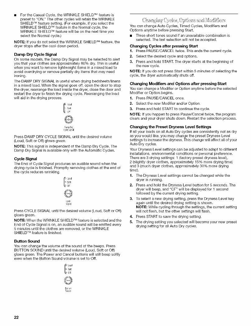
Button Sound
You can change the volume of the sound of the beeps. PressBUTTON SOUND until the desired volume (Loud, Soft or Off)glows green. The Power and Cancel buttons will still beep softlyeven when the Button Sound volume is set to Off.
i_Loud
i_Soft!_Off
You can change Auto Cycles, Timed Cycles, Modifiers andOptions anytime before pressing Start.
• Three short tones sound if an unavailable combination isselected. The last selection will not be accepted.
Changing Cycles after pressing Start1. Press PAUSE/CANCEL twice. This ends the current cycle.
2. Select the desired cycle and options.
3. Press and hold START, The dryer starts at the beginning ofthe new cycle.
NOTE: If you do not press Start within 5 minutes of selecting thecycle, the dryer automatically shuts off.
Changing Modifiers and Options after pressing Start
You can change a Modifier or Option anytime before the selectedModifier or Option begins.
1. Press PAUSE/CANCEL once.
2. Select the new Modifier and/or Option.
3. Press and hold START to continue the cycle.
NOTE: If you happen to press Pause/Cancel twice, the programclears and your dryer shuts down. Restart the selection process.
Changing the Preset Dryness Level SettingsIf all your loads on all Auto Dry cycles are consistently not as dryas you would like, you may change the preset Dryness Levelsettings to increase the dryness. This change will affect all of yourAuto Dry cycles.
Your Dryness Level settings can be adjusted to adapt to differentinstallations, environmental conditions or personal preference.There are 3 drying settings: 1 (factory preset dryness level),2 (slightly dryer clothes, approximately 15% more drying time)and 3 (much dryer clothes, approximately 30% more dryingtime).
1. The Dryness Level settings cannot be changed while thedryer is running.
2. Press and hold the Dryness Level button for 5 seconds. Thedryer will beep, and "CF" will be displayed for 1 secondfollowed by the current drying setting.
3. To select a new drying setting, press the Dryness Level keyagain until the desired drying setting is shown.NOTE: While cycling through the settings, the current settingwill not flash, but the other settings will flash.
4. Press START to save the drying setting.
5. The drying setting you selected will become your new presetdrying setting for all Auto Dry cycles.
ButtonSound
22

The drying rack is useful for drying items you would notnecessarily want to tumble dry or that you would normally line dry(for example, sweaters).
If your model does not have a drying rack, you may be able topurchase one for your model. To find out whether your modelallows drying rack usage and for information on ordering, pleaserefer to the front page of the manual or contact the dealer fromwhom you purchased your dryer.
To use the drying rack
Do not remove the lint screen.
1. Open dryer door.
2.
A. Front edge
Place drying rack inside dryer drum, positioning the back wireon the ledge of the inner dryer back panel. Push down onfront edge of drying rack to secure over the lint screen.
This chart shows examples of items that can be rack dried andthe suggested cycle, temperature setting and drying time. Actualdrying time will depend on the amount of moisture items hold.
Rack Dry Setting Temp. Time*
Wool Sweaters Timed Low 60
Block to shape and lay flat on Drythe rack,
Stuffed toys or pillows Timed Low 60
Cotton or polyester fiber filled Dry
Stuffed toys or pillows N/A Air Only 90
Foam rubber filled (no heat)
Sneakers or canvas shoes N/A Air Only 90
(no heat)
*(Minutes) Reset time to complete drying, if needed.
NOTE: You must remove rack for normal tumbling. Do not useautomatic cycles with the drying rack.
DRYERCARE
Keep dryer area clear and free from items that would obstruct theflow of combustion and ventilation air.
A. Dryer rack front edgeB. Dryer back panel
3. Put the wet items on top of the rack. Leave space betweenthe items so air can reach all the surfaces.
NOTE: Do not allow items to hang over the edge of the rack.
oj/4. Close the door.
5. Select a timed drying cycle and temperature, or an air cycle(see following chart). Items containing foam, rubber, or plasticmust be dried on a clothesline or by using the Air Onlytemperature setting.
6. You must select a time by pressing the DRY TIME up or downbuttons. Reset time as needed to complete drying. Refer tothe following table.
7. Press and hold START button (about 1 second).
NOTE: Check the lint screen and remove any lint accumulatedfrom items dried on the rack.
Explosion Hazard
Keep flammable materials and vapors, such asgasoline, away from dryer,
Place dryer at least 18 inches (46 cm) above the floorfor a garage installation,
Failure to do so can result in death, explosion, or fire.
Every load cleaning
The lint screen is located in the door opening of the dryer. Thecontrol panel has an indicator light to remind you to clean the lintscreen before each load. A screen blocked by lint can increasedrying time.
To clean
1. Pull the lint screen straight up. Roll lint off the screen withyour fingers. Do not rinse or wash screen to remove lint. Wetlint is hard to remove.
2. Push the lint screen firmly back into place.
23

IMPORTANT:
• Do not run the dryer with the lint screen loose, damaged,blocked, or missing. Doing so can cause overheating anddamage to both the dryer and fabrics.
• If lint falls off the screen into the dryer during removal, checkthe exhaust hood and remove the lint. See "VentingRequirements."
As needed cleaningLaundry detergent and fabric softener residue can build up on thelint screen. This buildup can cause longer drying times for yourclothes, or cause the dryer to stop before your load is completelydry. The screen is probably clogged if lint falls off while the screenis in the dryer.
Clean the lint screen with a nylon brush every 6 months, or morefrequently, if it becomes clogged due to a residue buildup.
To wash
1. Roll lint off the screen with your fingers.
2. Wet both sides of lint screen with hot water.
3. Wet a nylon brush with hot water and liquid detergent. Scrublint screen with the brush to remove residue buildup.
4. Rinse screen with hot water.
5. Thoroughly dry lint screen with a clean towel. Replace screenin dryer.
To clean dryer drum1. Make a paste with powdered laundry detergent and very
warm water.
2. Apply paste to a soft cloth.
OR
Apply a liquid, nonflammable household cleaner to thestained area and rub with a soft cloth until all excess dye andstains are removed.
3. Wipe drum thoroughly with a damp cloth.
4. Tumble a load of clean cloths or towels to dry drum.
NOTE: Garments that contain unstable dyes, such as denim bluejeans or brightly colored cotton items, may discolor the dryerinterior. These stains are not harmful to your dryer and will notstain future loads of clothes. Dry unstable dye items inside out toavoid dye transfer.
Vacation care
Operate your dryer only when you are at home. If you will be onvacation or not using your dryer for an extended period of time,you should:
f. Unplug dryer or disconnect power.
2. Clean lint screen. See "Cleaning the Lint Screen."
Moving care
For power supply cord-connected dryers:1. Unplug the power supply cord.
2. Make sure leveling legs are secure in dryer base.
3. Use masking tape to secure dryer door.
For direct-wired dryers:
Electrical Shock Hazard
Disconnect power before servicing.
Replace all parts and panels before operating.
Failure to do so can result in death or electrical shock.
1. Disconnect power.
2. Disconnect wiring.
3. Make sure leveling legs are secure in dryer base.
4. Use masking tape to secure dryer door.
The dryer light automatically turns on inside the dryer drum whenyou open the door.
To change the drum light1. Unplug dryer or disconnect power.
2. Open the dryer door. Locate the light bulb cover on the backwall of the dryer. Remove the screw located in the lower rightcorner of the cover. Remove the cover.
From Inside the Dryer CabinetLint should be removed every 2 years, or more often, dependingon dryer usage. Cleaning should be done by a qualified person.
From the Exhaust Vent
Lint should be removed every 2 years, or more often, dependingon dryer usage.
3. Turn bulb counterclockwise. Replace the bulb with a 10-wattappliance bulb only. Replace the cover and secure with thescrew.
4. Plug in dryer or reconnect power.
24

TROUBLESHOOTINGFirst try the solutions suggested here and possibly avoid the cost of a service call...
Dryer will not run
Has a household fuse blown, or has a circuit breakertripped?There may be 2 household fuses or circuit breakers for thedryer. Check that both fuses are intact and tight, or that bothcircuit breakers have not tripped. Replace the fuse or resetthe circuit breaker. If the problem continues, call anelectrician.
Is the correct power supply available?Electric dryers require 240-volt power supply. Check with aqualified electrician.
Was a regular fuse used?Use a time-delay fuse.
Is the dryer door firmly closed?
Was the Start button firmly pressed?Large loads may require pressing and holding the Startbutton for 2-5 seconds.
No heat
Has a household fuse blown, or has a circuit breakertripped?The drum may be turning, but you may not have heat. Electricdryers use 2 household fuses or circuit breakers. Replace thefuse or reset the circuit breaker. If the problem continues, callan electrician.
Unusual sounds
• Has the dryer had a period of non-use?If the dryer hasn't been used for a while, there may be athumping sound during the first few minutes of operation.
is a coin, button, or paper clip caught between the drumand front or rear of the dryer?Check the front and rear edges of the drum for small objects.Clean out pockets before laundering.
Are the four legs installed, and is the dryer level front toback and side to side?The dryer may vibrate if not properly installed. See theInstallation Instructions.
Is the clothing knotted or balled up?When balled up, the load will bounce, causing the dryer tovibrate. Separate the load items and restart the dryer.
Dryer displaying code message
• "PF" (power failure), check the following:Was the drying cycle interrupted by a power failure?Press and hold START to restart the dryer.
• "E" Variable (El, E2, E3) service codes:Call for service.
Clothes are not drying satisfactorily, drying times are toolong, or load is too hot
• is the lint screen clogged with lint?Lint screen should be cleaned before each load.
Fire Hazard
Use a heavy metal vent.
Do not use a plastic vent.
Do not use a metal foil vent.
Failure to follow these instructions can result in deathor fire.
Is the exhaust vent or outside exhaust hood clogged withlint, restricting air movement?Run the dryer for 5-10 minutes. Hold your hand under theoutside exhaust hood to check air movement. If you do notfeel air movement, clean exhaust system of lint or replaceexhaust vent with heavy metal or flexible metal vent. See theInstallation Instructions.
Are fabric softener sheets blocking the grille?Use only one fabric softener sheet, and use it only once.
Is the exhaust vent the correct length?Check that the exhaust vent is not too long or has too manyturns. Long venting will increase drying times. See theInstallation Instructions.
Is the exhaust vent diameter the correct size?Use 4" (10.2 cm) diameter vent material.
25
Explosion Hazard
Keep flammable materials and vapors, such asgasoline, away from dryer.
Place dryer at least 18 inches (46 cm) above the floorfor a garage installation.
Failure to do so can result in death, explosion, or fire.
Is the dryer located in a room with temperature below45°F (7°C)?Proper operation of dryer cycles requires temperatures above45°F (7°C).
Is the dryer located in a closet?Closet doors must have ventilation openings at the top andbottom of the door. The front of the dryer requires a minimumof 1" (2.5 cm) of airspace, and, for most installations, the rearof the dryer requires 5" (12.7 cm). See the InstallationInstructions.
• Has the Air Only temperature setting been selected?Select the right temperature for the types of garments beingdried. See "Additional Features."
• Is the load too large and heavy to dry quickly?Separate the load to tumble freely.
Cycle time too short
Excessive Weight Hazard
Use two or more people to move and install dryer.
Failure to do so can result in back or other injury.
• Is the automatic cycle ending early?The load may not be contacting the sensor strips. Level thedryer.
Change the dryness level setting on Automatic Cycles.Increasing or decreasing the dryness level will change theamount of drying time in a cycle.
Lint on load
• Is the lint screen clogged?Clean lint screen. Check for air movement.
Stains on load or drum
Was dryer fabric softener properly used?Add dryer fabric softener sheets at the beginning of the cycle.Fabric softener sheets added to a partially dried load canstain your garments.
Drum stains are caused by dyes in clothing (usually bluejeans). This will not transfer to other clothing.
Loads are wrinkled
• Was the load removed from dryer at the end of the cycle?
• Was the dryer overloaded?Dry smaller loads that can tumble freely.
Odors
Have you recently been painting, staining or varnishing inthe area where your dryer is located?If so, ventilate the area. When the odors or fumes are gonefrom the area, rewash and dry the clothing.
• Is the dryer being used for the first time?The new electric heating element may have an odor. The odorwill be gone after the first cycle.
26

ASSISTANCEORSERVICEBefore calling for assistance or service, please check"Troubleshooting." It may save you the cost of a service call. Ifyou still need help, follow the instructions below.
When calling, please know the purchase date and the completemodel and serial number of your appliance. This information willhelp us to better respond to your request.
If you need replacement partsIf you need to order replacement parts, we recommend that youuse only FSP®factory specified parts. These parts will fit rightand work right because they are made with the same precisionused to build every new WHIRLPOOL ®appliance. To locate FSP®replacement parts in your area, call our Customer experienceCenter telephone number or your nearest designated servicecenter.
For assistance and service
Call the Whirlpool Customer eXperience Center toll free:1-800-253-1301.
Our consultants provide assistance with:
• Features and specifications on our full line of appliances
• Installation information
• Use and maintenance procedures
• Accessory and repair parts sales
• Specialized customer assistance (Spanish speaking, hearingimpaired, limited vision, etc.)
• Referrals to local dealers, repair parts distributors, andservice companies
Whirlpool designated service technicians are trained to fulfill theproduct warranty and provide after-warranty service, anywhere inthe United States.
To locate the Whirlpool designated service company in your area,you can also look in your telephone directory Yellow Pages.
For further assistance
If you need further assistance, you can write to WhirlpoolCorporation with any questions or concerns at:
Whirlpool CorporationCustomer experience Center553 Benson RoadBenton Harbor, M149022-2692
Please include a daytime phone number in your correspondence.
Accessories U.S.A.
To order accessories, call the Whirlpool Customer eXperienceCenter toll free at 1-800-442-9991 and follow the menu prompts.Or visit our website at www.whirlpool.com.
27

WHIRLPOOLCORPORATIONMAJORAPPLIANCEWARRANTY
ONE YEAR LIMITED WARRANTY
For one year from the date of purchase, when this major appliance is operated and maintained according to instructions attached to orfurnished with the product, Whirlpool Corporation or Whirlpool Canada LP (hereafter "Whirlpool") will pay for Factory Specified Partsand repair labor to correct defects in materials or workmanship. Service must be provided by a Whirlpool designated service company.This limited warranty applies only when the major appliance is used in the country in which it was purchased.
ITEMS WHIRLPOOL WILL NOT PAY FOR
1. Service calls to correct the installation of your major appliance, to instruct you how to use your major appliance, to replace or repairhouse fuses or to correct house wiring or plumbing.
2. Service calls to repair or replace appliance light bulbs, air filters or water filters. Those consumable parts are excluded from warrantycoverage.
3. Repairs when your major appliance is used for other than normal, single-family household use.
4. Damage resulting from accident, alteration, misuse, abuse, fire, flood, acts of God, improper installation, installation not inaccordance with electrical or plumbing codes, or use of products not approved by Whirlpool.
5. Any food loss due to refrigerator or freezer product failures.
6. Replacement parts or repair labor costs for units operated outside the United States or Canada.
7. Pickup and delivery. This major appliance is designed to be repaired in the home.
8. Repairs to parts or systems resulting from unauthorized modifications made to the appliance.
9. Expenses for travel and transportation for product service in remote locations.
10. The removal and reinstallation of your appliance if it is installed in an inaccessible location or is not installed in accordance withpublished installation instructions.
11. Replacement parts or repair labor costs when the major appliance is used in a country other than the country in which it waspurchased.
DISCLAIMER OF IMPLIED WARRANTIES; LIMITATION OF REMEDIES
CUSTOMER'S SOLE AND EXCLUSIVE REMEDY UNDER THIS LIMITED WARRANTY SHALL BE PRODUCT REPAIR AS PROVIDEDHEREIN. IMPLIED WARRANTIES, INCLUDING WARRANTIES OF MERCHANTABILITY OR FITNESS FOR A PARTICULAR PURPOSE,ARE LIMITED TO ONE YEAR OR THE SHORTEST PERIOD ALLOWED BY LAW. WHIRLPOOL SHALL NOT BE LIABLE FORINCIDENTAL OR CONSEQUENTIAL DAMAGES. SOME STATES AND PROVINCES DO NOT ALLOW THE EXCLUSION OR LIMITATIONOF INCIDENTAL OR CONSEQUENTIAL DAMAGES, OR LIMITATIONS ON THE DURATION OF IMPLIED WARRANTIES OFMERCHANTABILITY OR FITNESS, SO THESE EXCLUSIONS OR LIMITATIONS MAY NOT APPLY TO YOU. THIS WARRANTY GIVESYOU SPECIFIC LEGAL RIGHTS AND YOU MAY ALSO HAVE OTHER RIGHTS, WHICH VARY FROM STATE TO STATE OR PROVINCETO PROVINCE.
Outside the 50 United States and Canada, this warranty does not apply. Contact your authorized Whirlpool dealer to determine ifanother warranty applies.
If you need service, first see the "Troubleshooting" section of the Use & Care Guide. After checking "Troubleshooting," additional helpcan be found by checking the "Assistance or Service" section or by calling Whirlpool. In the U.S.A., call 1-800-253-1301. In Canada,call 1-800-807-6777. 12/o5
Keep this book and your sales slip together for futurereference. You must provide proof of purchase or installationdate for in-warranty service.
Write down the following information about your major applianceto better help you obtain assistance or service if you ever need it.You will need to know your complete model number and serialnumber. You can find this information on the model and serialnumber label located on the product.
Dealer name
Address
Phone number
Model number
Serial number
Purchase date
W10110850A© 2006 Whirlpool Corporation.All rights reserved. ® Registered Trademark/TM Trademark of Whirlpool, U.S.A.
10/0 6Printed in U.S.A.