Embed Size (px)
Citation preview

Electronic ballast 2.5/5.0/6.0/7.5/9.0/10.0/11.0/12.0 kW 3AC
EBU2_120_0450_CxH0M34Tx_Manual_EN_V02.docx 08.04.2016
ELECTRONIC BALLAST 3x360-530 VAC wide-range input
Real, continuously variable power control (5% to 100% Efficiency of up to 98% thanks to EfficientSwitch™ Very compact and lightweight Design free from electrolytic capacitors Integrated HF ignitor with a sinus amplitude of 5kV Low-frequency AC square-wave operation Activation by means of analogue / digital I/O or field bus Integrated lamp management for gentle operation Parameterisable by means of software interface Suitable for all arc lengths and doped lamps Lamp cable lengths of up to 300m possible Several lamps can be connected in series Integrated event memory 2-year guarantee
Software-Interface OPA (Operating Performance Analyzer)
BRIEF DESCRIPTION The electronic ballasts (devices) are designed for operating UV
lamps. The devices are characterised by an especially high efficiency, a compact and lightweight design and low-frequency AC square-wave operation, which guarantees constant irradiation. The devices can thus operate virtually all UV lamps irrespective of their arc length or type of dose. As an option, the parameters (lamp current, lamp power, etc.) can be parameterised and monitored from the PC using the software interface OPA (Operating Performance Analyzer). The devices are exclusively made of high-quality materials and components manufactured in Europe. Each device undergoes a fully automatic 100% function test with a subsequent burn-in procedure during the production process.
SAFETY
KEY DATA
Protection category IP20 Power classes 2,5/5/6/7,5/9/10,0/ 11,0/12,0kW
Parameterisable from 5% to 100%
Protection class 1 Mains voltage 3x400-480 VAC ±10% Degree of contamination 2 Mains frequency 50 – 60 Hz ±10% Overvoltage category 3 Lamp voltage max. 450V at 3x360VAC Protection against foreign bodies Installation height
>5,5mm <2000m
Lamp voltage Lamp current Lamp current
Max. 585 V Max. 22.0 A Max. 28.5 A
at 3x480VAC
from 9,0kW to 10,0kW
Efficiency 98% typ. Temperature range 0°C to +40°C at full load Derating 6A/°C at +110°C on the
IGBT Lamp voltage
scaling factor 10mV/V
Dimensions 460x177x80mm LxBxH Net weight 4kg
MARKINGS
Electronic ballast 2.5/5.0/6.0/7.5/9.0/10.0/11.0/12.0 kW 3AC
EBU2_120_0450_CxH0M34Tx_Manual_EN_V02.docx 08.04.2016
Seite 1 von 33
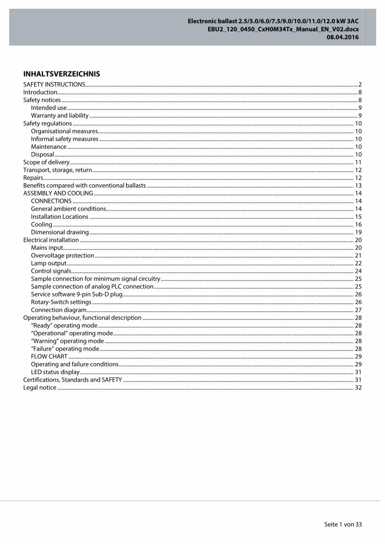
INHALTSVERZEICHNIS SAFETY INSTRUCTIONS ................................................................................................................................................................................................... 2 Introduction ....................................................................................................................................................................................................................... 8 Safety notices .................................................................................................................................................................................................................... 8
Intended use ................................................................................................................................................................................................................ 9 Warranty and liability ................................................................................................................................................................................................ 9
Safety regulations ......................................................................................................................................................................................................... 10 Organisational measures....................................................................................................................................................................................... 10 Informal safety measures ...................................................................................................................................................................................... 10 Maintenance ............................................................................................................................................................................................................. 10 Disposal ...................................................................................................................................................................................................................... 10
Scope of delivery ........................................................................................................................................................................................................... 11 Transport, storage, return ........................................................................................................................................................................................... 12 Repairs .............................................................................................................................................................................................................................. 12 Benefits compared with conventional ballasts .................................................................................................................................................... 13 ASSEMBLY AND COOLING .......................................................................................................................................................................................... 14
CONNECTIONS ......................................................................................................................................................................................................... 14 General ambient conditions ................................................................................................................................................................................. 14 Installation Locations ............................................................................................................................................................................................. 15 Cooling ....................................................................................................................................................................................................................... 16 Dimensional drawing ............................................................................................................................................................................................. 19
Electrical installation .................................................................................................................................................................................................... 20 Mains input................................................................................................................................................................................................................ 20 Overvoltage protection ......................................................................................................................................................................................... 21 Lamp output ............................................................................................................................................................................................................. 22 Control signals .......................................................................................................................................................................................................... 24 Sample connection for minimum signal circuitry .......................................................................................................................................... 25 Sample connection of analog PLC connection ............................................................................................................................................... 25 Service software 9-pin Sub-D plug ..................................................................................................................................................................... 26 Rotary-Switch settings ........................................................................................................................................................................................... 26 Connection diagram ............................................................................................................................................................................................... 27
Operating behaviour, functional description ....................................................................................................................................................... 28 “Ready” operating mode ....................................................................................................................................................................................... 28 “Operational” operating mode ............................................................................................................................................................................ 28 “Warning” operating mode .................................................................................................................................................................................. 28 “Failure” operating mode ...................................................................................................................................................................................... 28 FLOW CHART ............................................................................................................................................................................................................ 29 Operating and failure conditions ........................................................................................................................................................................ 29 LED status display .................................................................................................................................................................................................... 31
Certifications, Standards and SAFETY ..................................................................................................................................................................... 31 Legal notice .................................................................................................................................................................................................................... 32
Electronic ballast 2.5/5.0/6.0/7.5/9.0/10.0/11.0/12.0 kW 3AC
EBU2_120_0450_CxH0M34Tx_Manual_EN_V02.docx 08.04.2016
Seite 2 von 33
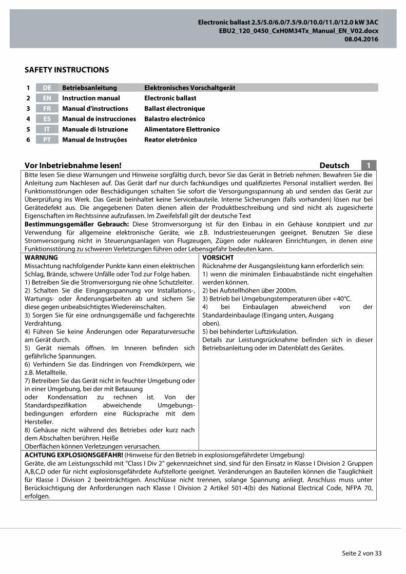
SAFETY INSTRUCTIONS
Vor Inbetriebnahme lesen! Deutsch 1 Bitte lesen Sie diese Warnungen und Hinweise sorgfältig durch, bevor Sie das Gerät in Betrieb nehmen. Bewahren Sie die Anleitung zum Nachlesen auf. Das Gerät darf nur durch fachkundiges und qualifiziertes Personal installiert werden. Bei Funktionsstörungen oder Beschädigungen schalten Sie sofort die Versorgungsspannung ab und senden das Gerät zur Überprüfung ins Werk. Das Gerät beinhaltet keine Servicebauteile. Interne Sicherungen (falls vorhanden) lösen nur bei Gerätedefekt aus. Die angegebenen Daten dienen allein der Produktbeschreibung und sind nicht als zugesicherte Eigenschaften im Rechtssinne aufzufassen. Im Zweifelsfall gilt der deutsche Text Bestimmungsgemäßer Gebrauch: Diese Stromversorgung ist für den Einbau in ein Gehäuse konzipiert und zur Verwendung für allgemeine elektronische Geräte, wie z.B. Industriesteuerungen geeignet. Benutzen Sie diese Stromversorgung nicht in Steuerungsanlagen von Flugzeugen, Zügen oder nuklearen Einrichtungen, in denen eine Funktionsstörung zu schweren Verletzungen führen oder Lebensgefahr bedeuten kann. WARNUNG Missachtung nachfolgender Punkte kann einen elektrischen Schlag, Brände, schwere Unfälle oder Tod zur Folge haben. 1) Betreiben Sie die Stromversorgung nie ohne Schutzleiter. 2) Schalten Sie die Eingangsspannung vor Installations-, Wartungs- oder Änderungsarbeiten ab und sichern Sie diese gegen unbeabsichtigtes Wiedereinschalten. 3) Sorgen Sie für eine ordnungsgemäße und fachgerechte Verdrahtung. 4) Führen Sie keine Änderungen oder Reparaturversuche am Gerät durch. 5) Gerät niemals öffnen. Im Inneren befinden sich gefährliche Spannungen. 6) Verhindern Sie das Eindringen von Fremdkörpern, wie z.B. Metallteile. 7) Betreiben Sie das Gerät nicht in feuchter Umgebung oder in einer Umgebung, bei der mit Betauung oder Kondensation zu rechnen ist. Von der Standardspezifikation abweichende Umgebungs-bedingungen erfordern eine Rücksprache mit dem Hersteller. 8) Gehäuse nicht während des Betriebes oder kurz nach dem Abschalten berühren. Heiße Oberflächen können Verletzungen verursachen.
VORSICHT Rücknahme der Ausgangsleistung kann erforderlich sein: 1) wenn die minimalen Einbauabstände nicht eingehalten werden können. 2) bei Aufstellhöhen über 2000m. 3) Betrieb bei Umgebungstemperaturen über +40°C. 4) bei Einbaulagen abweichend von der Standardeinbaulage (Eingang unten, Ausgang oben). 5) bei behinderter Luftzirkulation. Details zur Leistungsrücknahme befinden sich in dieser Betriebsanleitung oder im Datenblatt des Gerätes.
ACHTUNG EXPLOSIONSGEFAHR! (Hinweise für den Betrieb in explosionsgefährdeter Umgebung) Geräte, die am Leistungsschild mit "Class I Div 2" gekennzeichnet sind, sind für den Einsatz in Klasse I Division 2 Gruppen A,B,C,D oder für nicht explosionsgefährdete Aufstellorte geeignet. Veränderungen an Bauteilen können die Tauglichkeit für Klasse I Division 2 beeinträchtigen. Anschlüsse nicht trennen, solange Spannung anliegt. Anschluss muss unter Berücksichtigung der Anforderungen nach Klasse I Division 2 Artikel 501-4(b) des National Electrical Code, NFPA 70, erfolgen.
1 DE Betriebsanleitung Elektronisches Vorschaltgerät 2 EN Instruction manual Electronic ballast 3 FR Manual d'instructions Ballast électronique 4 ES Manual de instrucciones Balastro electrónico 5 IT Manuale di Istruzione Alimentatore Elettronico 6 PT Manual de Instruções Reator eletrônico
Electronic ballast 2.5/5.0/6.0/7.5/9.0/10.0/11.0/12.0 kW 3AC
EBU2_120_0450_CxH0M34Tx_Manual_EN_V02.docx 08.04.2016
Seite 3 von 33
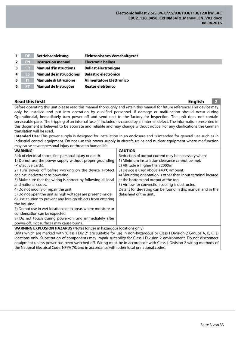
Read this first! English 2 Before operating this unit please read this manual thoroughly and retain this manual for future reference! This device may only be installed and put into operation by qualified personnel. If damage or malfunction should occur during Operationalal, immediately turn power off and send unit to the factory for inspection. The unit does not contain serviceable parts. The tripping of an internal fuse (if included) is caused by an internal defect. The information presented in this document is believed to be accurate and reliable and may change without notice. For any clarifications the German translation will be used. Intended Use: This power supply is designed for installation in an enclosure and is intended for general use such as in industrial control equipment. Do not use this power supply in aircraft, trains and nuclear equipment where malfunction may cause severe personal injury or threaten human life. WARNING Risk of electrical shock, fire, personal injury or death. 1) Do not use the power supply without proper grounding (Protective Earth). 2) Turn power off before working on the device. Protect against inadvertent re-powering. 3) Make sure that the wiring is correct by following all local and national codes. 4) Do not modify or repair the unit. 5) Do not open the unit as high voltages are present inside. 6) Use caution to prevent any foreign objects from entering the housing. 7) Do not use in wet locations or in areas where moisture or condensation can be expected. 8) Do not touch during power-on, and immediately after power-off. Hot surfaces may cause burns.
CAUTION Reduction of output current may be necessary when: 1) Minimum installation clearance cannot be met. 2) Altitude is higher than 2000m 3) Device is used above +40°C ambient. 4) Mounting orientation is other than input terminal located at the bottom and output at the top. 5) Airflow for convection cooling is obstructed. Details for de-rating can be found in this manual and in the datasheet of the unit..
WARNING EXPLOSION HAZARDS (Notes for use in hazardous locations only) Units which are marked with "Class I Div 2" are suitable for use in non-hazardous or Class I Division 2 Groups A, B, C, D locations only. Substitution of components may impair suitability for Class I Division 2 environment. Do not disconnect equipment unless power has been switched off. Wiring must be in accordance with Class I, Division 2 wiring methods of the National Electrical Code, NFPA 70, and in accordance with other local or national codes.
1 DE Betriebsanleitung Elektronisches Vorschaltgerät 2 EN Instruction manual Electronic ballast 3 FR Manual d'instructions Ballast électronique 4 ES Manual de instrucciones Balastro electrónico 5 IT Manuale di Istruzione Alimentatore Elettronico 6 PT Manual de Instruções Reator eletrônico
Electronic ballast 2.5/5.0/6.0/7.5/9.0/10.0/11.0/12.0 kW 3AC
EBU2_120_0450_CxH0M34Tx_Manual_EN_V02.docx 08.04.2016
Seite 4 von 33
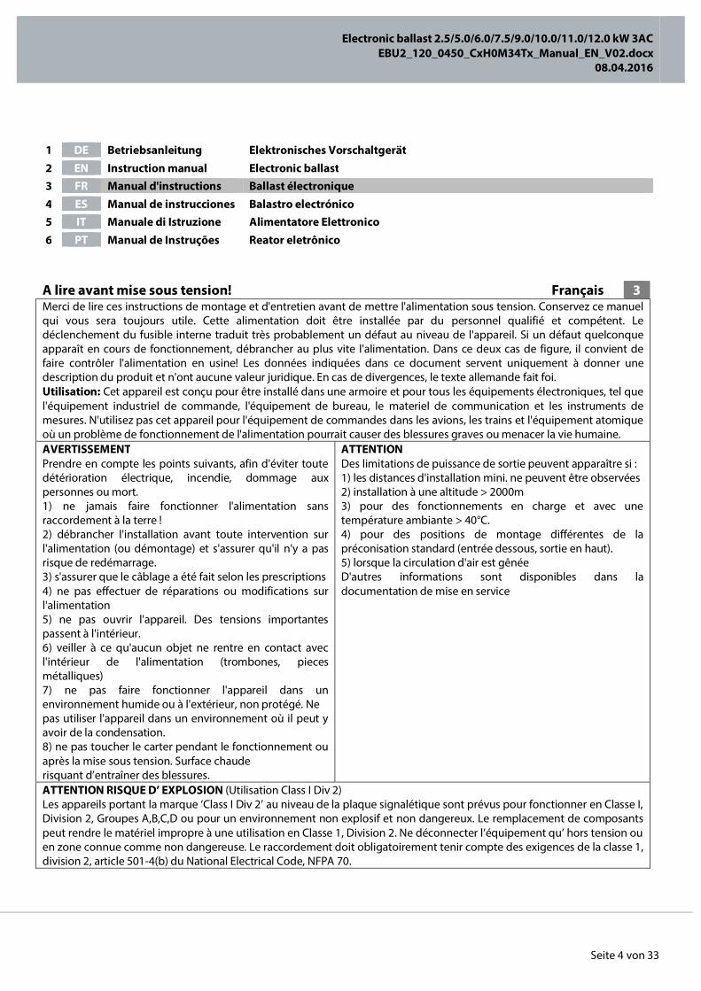
A lire avant mise sous tension! Français 3 Merci de lire ces instructions de montage et d'entretien avant de mettre l'alimentation sous tension. Conservez ce manuel qui vous sera toujours utile. Cette alimentation doit être installée par du personnel qualifié et compétent. Le déclenchement du fusible interne traduit très probablement un défaut au niveau de l'appareil. Si un défaut quelconque apparaît en cours de fonctionnement, débrancher au plus vite l'alimentation. Dans ce deux cas de figure, il convient de faire contrôler l'alimentation en usine! Les données indiquées dans ce document servent uniquement à donner une description du produit et n'ont aucune valeur juridique. En cas de divergences, le texte allemande fait foi. Utilisation: Cet appareil est conçu pour être installé dans une armoire et pour tous les équipements électroniques, tel que l'équipement industriel de commande, l'équipement de bureau, le materiel de communication et les instruments de mesures. N'utilisez pas cet appareil pour l'équipement de commandes dans les avions, les trains et l'équipement atomique où un problème de fonctionnement de l'alimentation pourrait causer des blessures graves ou menacer la vie humaine. AVERTISSEMENT Prendre en compte les points suivants, afin d'éviter toute détérioration électrique, incendie, dommage aux personnes ou mort. 1) ne jamais faire fonctionner l'alimentation sans raccordement à la terre ! 2) débrancher l'installation avant toute intervention sur l'alimentation (ou démontage) et s'assurer qu'il n'y a pas risque de redémarrage. 3) s'assurer que le câblage a été fait selon les prescriptions 4) ne pas effectuer de réparations ou modifications sur l'alimentation 5) ne pas ouvrir l'appareil. Des tensions importantes passent à l'intérieur. 6) veiller à ce qu'aucun objet ne rentre en contact avec l'intérieur de l'alimentation (trombones, pieces métalliques) 7) ne pas faire fonctionner l'appareil dans un environnement humide ou à l'extérieur, non protégé. Ne pas utiliser l'appareil dans un environnement où il peut y avoir de la condensation. 8) ne pas toucher le carter pendant le fonctionnement ou après la mise sous tension. Surface chaude risquant d’entraîner des blessures.
ATTENTION Des limitations de puissance de sortie peuvent apparaître si : 1) les distances d'installation mini. ne peuvent être observées 2) installation à une altitude > 2000m 3) pour des fonctionnements en charge et avec une température ambiante > 40°C. 4) pour des positions de montage différentes de la préconisation standard (entrée dessous, sortie en haut). 5) lorsque la circulation d'air est gênée D'autres informations sont disponibles dans la documentation de mise en service
ATTENTION RISQUE D’ EXPLOSION (Utilisation Class I Div 2) Les appareils portant la marque ‘Class I Div 2’ au niveau de la plaque signalétique sont prévus pour fonctionner en Classe I, Division 2, Groupes A,B,C,D ou pour un environnement non explosif et non dangereux. Le remplacement de composants peut rendre le matériel impropre à une utilisation en Classe 1, Division 2. Ne déconnecter l’équipement qu’ hors tension ou en zone connue comme non dangereuse. Le raccordement doit obligatoirement tenir compte des exigences de la classe 1, division 2, article 501-4(b) du National Electrical Code, NFPA 70.
1 DE Betriebsanleitung Elektronisches Vorschaltgerät 2 EN Instruction manual Electronic ballast 3 FR Manual d'instructions Ballast électronique 4 ES Manual de instrucciones Balastro electrónico 5 IT Manuale di Istruzione Alimentatore Elettronico 6 PT Manual de Instruções Reator eletrônico

Electronic ballast 2.5/5.0/6.0/7.5/9.0/10.0/11.0/12.0 kW 3AC
EBU2_120_0450_CxH0M34Tx_Manual_EN_V02.docx 08.04.2016
Seite 5 von 33
Lea primero! Español 4 Conserve este manual como referencia para futuras consultas. La fuente de alimentación solo puede ser instalada y puesta en funcionamiento por personal cualificado. Por favor lea detenidamente este manual antes de conectar la fuente de alimentación. Cuando se funde un fusible interno, existe gran probabilidad de un fallo interno en el equipo.Si se produce un fallo o mal funcionamiento durante la operación, desconecte inmediatamente la tensión de alimentación. En ambos casos, el equipo debe ser inspeccionado en fábrica. La información presentada en este documento es exacta y fiable en cuanto a la descripción del producto y puede cambiar sin aviso. En casa de duda, prevalece el texto alemán. Uso apropiado: Este equipo ha sido diseñado para su instalación en un ambiente cerrado y ha sido concebido para uso general en instalaciones de control industrial, oficinas, comunicaciones y equipos de instrumentación. No emplee este equipo en aeronaves, trenes e instalaciones atómicas, donde un mal funcionamiento de la fuente de alimentación puede ocasionar lesiones graves o riesgo mortal. ADVERTENCIA Riesgo de descarga eléctrica, incendio, accidente grave o muerte. 1) No conectar nunca la unidad sin conexión de puesta a tierra. 2) Desconectar la tensión de red antes de trabajar en la fuente de alimentación. Evite una possible reconexión involuntaria. 3) Asegurarse de que el cableado es correcto de acuerdo a los códigos locales y nacionales. 4) No realizar ninguna modificación o reparación de la unidad. 5) No abrir nunca la unidad. En el interior existe riesgo de altas tensiones. 6) Evitar la introducción en la carcasa de objetos extraños. 7) No usar el equipo en ambientes húmedos. No operar el equipo en ambientes donde se espere la formación de rocío o condensación. 8) No tocar durante el funcionamiento ni inmediatamente después del apagado. El calor de la superficie puede causar quemaduras graves
ATENCIÓN La deriva en la tensión de salida se produce: 1) cuando no pueden mantenerse las distancias mínimas de montaje. 2) en caso de que el montaje se realice en altitudes superiores a los 2000m. 3) en caso de funcionamiento a plena carga y temperaturas ambientales superiores a +40°C. 4) en caso de posiciones de montaje diferentes a la posición de montaje estándar (terminales de entrada abajo y terminales de salida arriba). 5) en caso de que la circulación de aire para la refrigeración por conducción esté obstruida. Puede encontrar más detalles del caso de deriva en este manual.
ATENCIÓN PELIGRO DE EXPLOSIÓN! (Uso apropiado Class I Div 2) Los equipos marcados con la expresión "Class I Div 2" son adecuados para su uso en ambientes no peligrosos y en entornos con la Clase I División 2 Grupos A, B, C, D. La sustitución de componentes puede perjudicar la idoneidad para la Clase I División 2. No desconecte el equipo a menos que la tensión de alimentación esté desconectada. El conexionado debe cumplir con la Clase I División 2 métodos de conexión del Código Nacional Eléctrico NFPA 70 o con el resto de códigos locales o nacionales.
1 DE Betriebsanleitung Elektronisches Vorschaltgerät 2 EN Instruction manual Electronic ballast 3 FR Manual d'instructions Ballast électronique 4 ES Manual de instrucciones Balastro electrónico 5 IT Manuale di Istruzione Alimentatore Elettronico 6 PT Manual de Instruções Reator eletrônico
Electronic ballast 2.5/5.0/6.0/7.5/9.0/10.0/11.0/12.0 kW 3AC
EBU2_120_0450_CxH0M34Tx_Manual_EN_V02.docx 08.04.2016
Seite 6 von 33
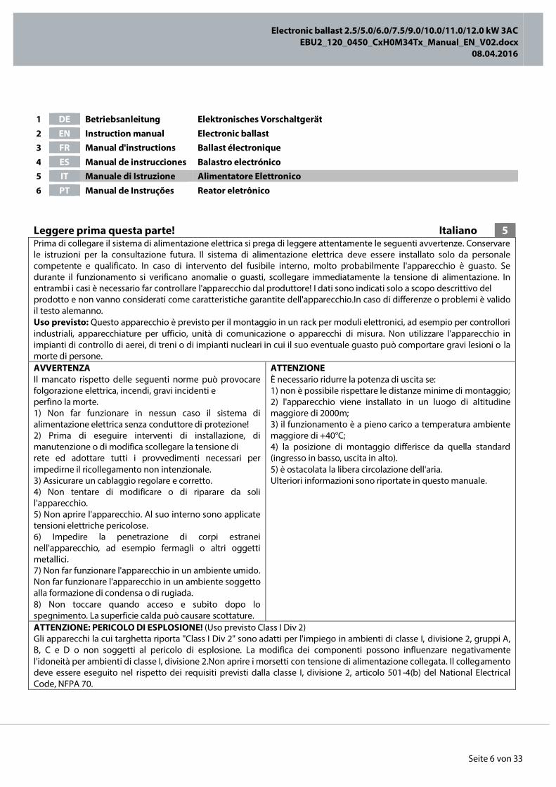
Leggere prima questa parte! Italiano 5 Prima di collegare il sistema di alimentazione elettrica si prega di leggere attentamente le seguenti avvertenze. Conservare le istruzioni per la consultazione futura. Il sistema di alimentazione elettrica deve essere installato solo da personale competente e qualificato. In caso di intervento del fusibile interno, molto probabilmente l'apparecchio è guasto. Se durante il funzionamento si verificano anomalie o guasti, scollegare immediatamente la tensione di alimentazione. In entrambi i casi è necessario far controllare l'apparecchio dal produttore! I dati sono indicati solo a scopo descrittivo del prodotto e non vanno considerati come caratteristiche garantite dell'apparecchio.In caso di differenze o problemi è valido il testo alemanno. Uso previsto: Questo apparecchio è previsto per il montaggio in un rack per moduli elettronici, ad esempio per controllori industriali, apparecchiature per ufficio, unità di comunicazione o apparecchi di misura. Non utilizzare l'apparecchio in impianti di controllo di aerei, di treni o di impianti nucleari in cui il suo eventuale guasto può comportare gravi lesioni o la morte di persone. AVVERTENZA Il mancato rispetto delle seguenti norme può provocare folgorazione elettrica, incendi, gravi incidenti e perfino la morte. 1) Non far funzionare in nessun caso il sistema di alimentazione elettrica senza conduttore di protezione! 2) Prima di eseguire interventi di installazione, di manutenzione o di modifica scollegare la tensione di rete ed adottare tutti i provvedimenti necessari per impedirne il ricollegamento non intenzionale. 3) Assicurare un cablaggio regolare e corretto. 4) Non tentare di modificare o di riparare da soli l'apparecchio. 5) Non aprire l'apparecchio. Al suo interno sono applicate tensioni elettriche pericolose. 6) Impedire la penetrazione di corpi estranei nell'apparecchio, ad esempio fermagli o altri oggetti metallici. 7) Non far funzionare l'apparecchio in un ambiente umido. Non far funzionare l'apparecchio in un ambiente soggetto alla formazione di condensa o di rugiada. 8) Non toccare quando acceso e subito dopo lo spegnimento. La superficie calda può causare scottature.
ATTENZIONE È necessario ridurre la potenza di uscita se: 1) non è possibile rispettare le distanze minime di montaggio; 2) l'apparecchio viene installato in un luogo di altitudine maggiore di 2000m; 3) il funzionamento è a pieno carico a temperatura ambiente maggiore di +40°C; 4) la posizione di montaggio differisce da quella standard (ingresso in basso, uscita in alto). 5) è ostacolata la libera circolazione dell'aria. Ulteriori informazioni sono riportate in questo manuale.
ATTENZIONE: PERICOLO DI ESPLOSIONE! (Uso previsto Class I Div 2) Gli apparecchi la cui targhetta riporta "Class I Div 2" sono adatti per l'impiego in ambienti di classe I, divisione 2, gruppi A, B, C e D o non soggetti al pericolo di esplosione. La modifica dei componenti possono influenzare negativamente l'idoneità per ambienti di classe I, divisione 2.Non aprire i morsetti con tensione di alimentazione collegata. Il collegamento deve essere eseguito nel rispetto dei requisiti previsti dalla classe I, divisione 2, articolo 501-4(b) del National Electrical Code, NFPA 70.
1 DE Betriebsanleitung Elektronisches Vorschaltgerät 2 EN Instruction manual Electronic ballast 3 FR Manual d'instructions Ballast électronique 4 ES Manual de instrucciones Balastro electrónico 5 IT Manuale di Istruzione Alimentatore Elettronico 6 PT Manual de Instruções Reator eletrônico
Electronic ballast 2.5/5.0/6.0/7.5/9.0/10.0/11.0/12.0 kW 3AC
EBU2_120_0450_CxH0M34Tx_Manual_EN_V02.docx 08.04.2016
Seite 7 von 33
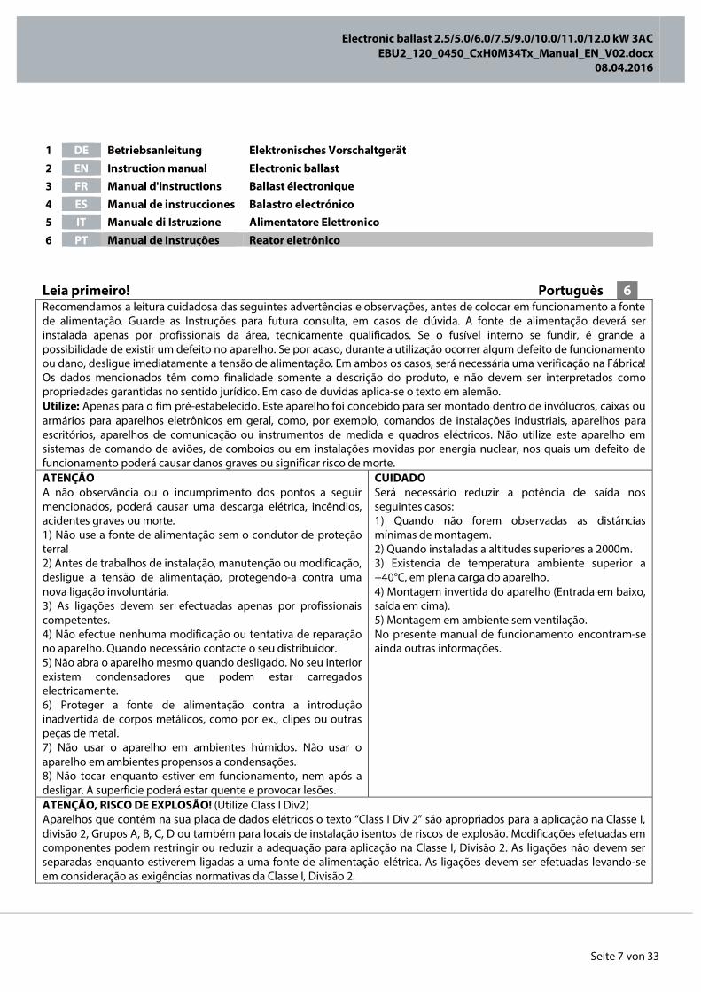
Leia primeiro! Portuguès 6 Recomendamos a leitura cuidadosa das seguintes advertências e observações, antes de colocar em funcionamento a fonte de alimentação. Guarde as Instruções para futura consulta, em casos de dúvida. A fonte de alimentação deverá ser instalada apenas por profissionais da área, tecnicamente qualificados. Se o fusível interno se fundir, é grande a possibilidade de existir um defeito no aparelho. Se por acaso, durante a utilização ocorrer algum defeito de funcionamento ou dano, desligue imediatamente a tensão de alimentação. Em ambos os casos, será necessária uma verificação na Fábrica! Os dados mencionados têm como finalidade somente a descrição do produto, e não devem ser interpretados como propriedades garantidas no sentido jurídico. Em caso de duvidas aplica-se o texto em alemão. Utilize: Apenas para o fim pré-estabelecido. Este aparelho foi concebido para ser montado dentro de invólucros, caixas ou armários para aparelhos eletrônicos em geral, como, por exemplo, comandos de instalações industriais, aparelhos para escritórios, aparelhos de comunicação ou instrumentos de medida e quadros eléctricos. Não utilize este aparelho em sistemas de comando de aviões, de comboios ou em instalações movidas por energia nuclear, nos quais um defeito de funcionamento poderá causar danos graves ou significar risco de morte. ATENÇÃO A não observância ou o incumprimento dos pontos a seguir mencionados, poderá causar uma descarga elétrica, incêndios, acidentes graves ou morte. 1) Não use a fonte de alimentação sem o condutor de proteção terra! 2) Antes de trabalhos de instalação, manutenção ou modificação, desligue a tensão de alimentação, protegendo-a contra uma nova ligação involuntária. 3) As ligações devem ser efectuadas apenas por profissionais competentes. 4) Não efectue nenhuma modificação ou tentativa de reparação no aparelho. Quando necessário contacte o seu distribuidor. 5) Não abra o aparelho mesmo quando desligado. No seu interior existem condensadores que podem estar carregados electricamente. 6) Proteger a fonte de alimentação contra a introdução inadvertida de corpos metálicos, como por ex., clipes ou outras peças de metal. 7) Não usar o aparelho em ambientes húmidos. Não usar o aparelho em ambientes propensos a condensações. 8) Não tocar enquanto estiver em funcionamento, nem após a desligar. A superficie poderá estar quente e provocar lesões.
CUIDADO Será necessário reduzir a potência de saída nos seguintes casos: 1) Quando não forem observadas as distâncias mínimas de montagem. 2) Quando instaladas a altitudes superiores a 2000m. 3) Existencia de temperatura ambiente superior a +40°C, em plena carga do aparelho. 4) Montagem invertida do aparelho (Entrada em baixo, saída em cima). 5) Montagem em ambiente sem ventilação. No presente manual de funcionamento encontram-se ainda outras informações.
ATENÇÃO, RISCO DE EXPLOSÃO! (Utilize Class I Div2) Aparelhos que contêm na sua placa de dados elétricos o texto “Class I Div 2” são apropriados para a aplicação na Classe I, divisão 2, Grupos A, B, C, D ou também para locais de instalação isentos de riscos de explosão. Modificações efetuadas em componentes podem restringir ou reduzir a adequação para aplicação na Classe I, Divisão 2. As ligações não devem ser separadas enquanto estiverem ligadas a uma fonte de alimentação elétrica. As ligações devem ser efetuadas levando-se em consideração as exigências normativas da Classe I, Divisão 2.
1 DE Betriebsanleitung Elektronisches Vorschaltgerät 2 EN Instruction manual Electronic ballast 3 FR Manual d'instructions Ballast électronique 4 ES Manual de instrucciones Balastro electrónico 5 IT Manuale di Istruzione Alimentatore Elettronico 6 PT Manual de Instruções Reator eletrônico
Electronic ballast 2.5/5.0/6.0/7.5/9.0/10.0/11.0/12.0 kW 3AC
EBU2_120_0450_CxH0M34Tx_Manual_EN_V02.docx 08.04.2016
Seite 8 von 33
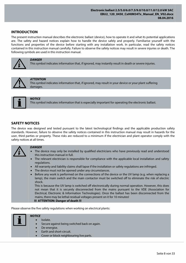
INTRODUCTION The present instruction manual describes the electronic ballast (device), how to operate it and what its potential applications are. The safety and hazard notices explain how to handle the device safely and properly. Familiarise yourself with the functions and properties of the device before starting with any installation work. In particular, read the safety notices contained in this instruction manual carefully. Failure to observe the safety notices may result in severe injuries or death. The following symbols are used in this instruction manual.
DANGER This symbol indicates information that, if ignored, may instantly result in death or severe injuries.
ATTENTION This symbol indicates information that, if ignored, may result in your device or your plant suffering damages.
NOTICE This symbol indicates information that is especially important for operating the electronic ballast.
SAFETY NOTICES The device was designed and tested pursuant to the latest technological findings and the applicable production safety standards. However, failure to observe the safety notices contained in this instruction manual may result in hazards for the user, third parties or property. These risks are reduced to a minimum if the electrician and plant operator comply with the safety notices at all times.
DANGER The device may only be installed by qualified electricians who have previously read and understood
this instruction manual in full. The relevant electrician is responsible for compliance with the applicable local installation and safety
regulations. All warranty and liability claims shall lapse if the installation or safety regulations are infringed. The device must not be opened under any circumstances. Before any work is performed on the connections of the device or the UV lamp (e.g. when replacing a
lamp), the main switch and the main contactor must be switched off to eliminate the risk of electric shock.
This is because the UV lamp is switched off electronically during normal operation. However, this does not mean that it is securely disconnected from the mains pursuant to the VDE (Association for Electrical, Electronic & Information Technologies). Once the ballast has been disconnected from the mains, there may be lethal residual voltages present on it for 10 minutes!
!!! ATTENTION: Danger of death !!! Please observe the five safety regulations when working on electrical plants:
NOTICE Isolate. Secure against being switched back on again. De-energise. Earth and short-circuit. Cover or block neighbouring live parts.
Electronic ballast 2.5/5.0/6.0/7.5/9.0/10.0/11.0/12.0 kW 3AC
EBU2_120_0450_CxH0M34Tx_Manual_EN_V02.docx 08.04.2016
Seite 9 von 33
INTENDED USE The device is an electronic ballast for UV lamps. Any other use shall be deemed unintended and may be dangerous. The user may operate the device only while observing all the safety and usage notices contained in the present instruction manual. Intended use also includes:
Observation of all of the notices contained in the instruction manual Observation of the general and special safety notices contained in the instruction manual Compliance with the relevant accident prevention regulations The device may not be used in aeroplanes, trains or nuclear plants, where the electronic ballast malfunctioning could
result in injuries or endanger human life
ATTENTION It is prohibited to operate the device in potentially explosive environments!
NOTICE The manufacturer accepts no liability for damages caused by unintended use. Any changes made to the ballast that were not checked and approved by the manufacturer are
impermissible..
WARRANTY AND LIABILITY The manufacturer’s “General Conditions of Sale and Delivery” apply. Warranty and liability claims are generally excluded in the event of bodily injuries and property damage, especially when these can be traced back to one or more of the following causes:
Unintended use of the device Improper assembly, commissioning and operation of the electronic ballast Operation of the device when the safety and protective equipment is defective and/or not functional Failure to observe the notices contained in the instruction manual with regard to safety, transport, storage, assembly,
commissioning, operation and maintenance Any unauthorised interventions in and changes or repairs made to the device by the user The impact of foreign bodies or force majeure (lightning, overvoltage, water damage, etc.) Transport damages and all other damages caused after the point in time at which the risk transferred to the customer
and any damages caused by improper packaging by the same Transport damages and all other damages caused by the customer returning the device to the manufacturer (e.g. for
the purpose of inspection or repair).
Electronic ballast 2.5/5.0/6.0/7.5/9.0/10.0/11.0/12.0 kW 3AC
EBU2_120_0450_CxH0M34Tx_Manual_EN_V02.docx 08.04.2016
Seite 10 von 33
SAFETY REGULATIONS
ORGANISATIONAL MEASURES The functions of all the safety equipment provided must be checked on a regular basis before starting any work and/or when changing shifts. Ensure that there are no externally visible damages.
INFORMAL SAFETY MEASURES In addition to the instruction manual, the generally valid and the local accident prevention and environmental protection regulations must be provided and observed.
MAINTENANCE The device is maintenance-free and designed for a service life (MTBF) of 60,000 hours. The maintenance intervals on the control cabinet must be amended depending on the prevalent ambient conditions (especially dust loading). The following checks may be performed by the equipment operator. If problems are identified while these checks are being performed, please contact the manufacturer.
Inspect the device for any visible external damage Check all of the electrical lines to ensure that they are in a perfect condition Loose cable connections must be remedied without delay and damaged cables must be replaced immediately Clean the filter inserts in the control cabinet
DANGER Danger is caused by direct or indirect electrical contact. Observe the notices contained in the chapter entitled “Safety notices” Seite 8)
DISPOSAL Once its service life has elapsed, please dispose of the device pursuant to the disposal regulations applicable at the installation location at the present point in time. You can also return the device to the manufacturer at your expense to ensure that it is disposed of properly. To find the correct address, please contact your local supplier of the device.
Electronic ballast 2.5/5.0/6.0/7.5/9.0/10.0/11.0/12.0 kW 3AC
EBU2_120_0450_CxH0M34Tx_Manual_EN_V02.docx 08.04.2016
Seite 11 von 33
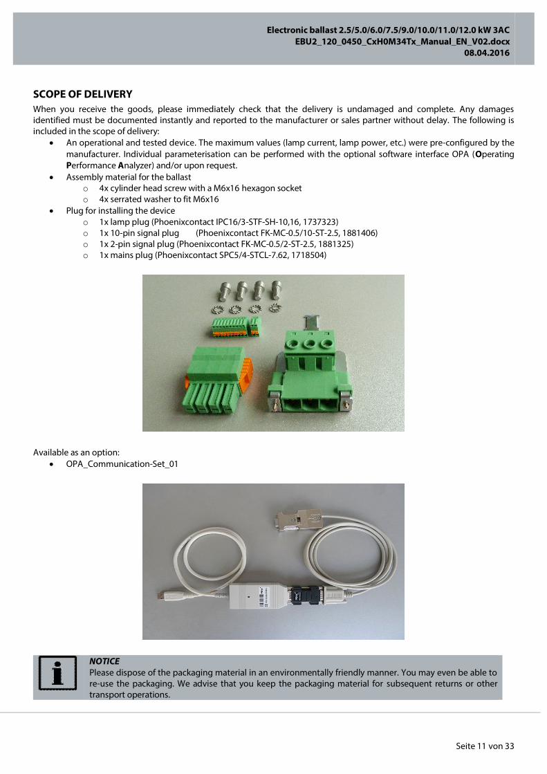
SCOPE OF DELIVERY When you receive the goods, please immediately check that the delivery is undamaged and complete. Any damages identified must be documented instantly and reported to the manufacturer or sales partner without delay. The following is included in the scope of delivery:
An operational and tested device. The maximum values (lamp current, lamp power, etc.) were pre-configured by the manufacturer. Individual parameterisation can be performed with the optional software interface OPA (Operating Performance Analyzer) and/or upon request.
Assembly material for the ballast o 4x cylinder head screw with a M6x16 hexagon socket o 4x serrated washer to fit M6x16
Plug for installing the device o 1x lamp plug (Phoenixcontact IPC16/3-STF-SH-10,16, 1737323) o 1x 10-pin signal plug (Phoenixcontact FK-MC-0.5/10-ST-2.5, 1881406) o 1x 2-pin signal plug (Phoenixcontact FK-MC-0.5/2-ST-2.5, 1881325) o 1x mains plug (Phoenixcontact SPC5/4-STCL-7.62, 1718504)
Available as an option:
OPA_Communication-Set_01
NOTICE Please dispose of the packaging material in an environmentally friendly manner. You may even be able to re-use the packaging. We advise that you keep the packaging material for subsequent returns or other transport operations.

Electronic ballast 2.5/5.0/6.0/7.5/9.0/10.0/11.0/12.0 kW 3AC
EBU2_120_0450_CxH0M34Tx_Manual_EN_V02.docx 08.04.2016
Seite 12 von 33
TRANSPORT, STORAGE, RETURN The device is supplied in cardboard packaging pursuant to the DIN/ISO 2248/2206 standard and is permissible for parcel service. The following ambient conditions must not be exceeded at any time during transport and storage:
Temperature range -10°C to +55°C during storage Temperature range -50°C to +95°C during transport Air humidity 5% to 95% non-condensing (during transport and storage)
Avoid temporarily storing the device outdoors for extended periods of time when it is unsupervised and unprotected. If you are returning or forwarding the device, ensure that the original packaging elements (foam inserts and cardboard packaging) are used and positioned correctly. Ensure that both the packaging base and packaging lid are bonded correctly. The device must be packaged as shown in the following figure.
ATTENTION If the device is being shipped, only the original packaging may be used. Otherwise, damage to the device is unavoidable.
If the original packaging elements are unavailable, please consult with the manufacturer. Packaging can be requested from the manufacturer for a charge.
REPAIRS If the device suffers damages or defects of any kind, the device must be returned to the manufacturer for checking or repairs.
DANGER Opening of the device is prohibited and may instantly result in death or severe injuries.
NOTICE Any guarantee claim shall lapse if the device is opened or the device seal is broken!

Electronic ballast 2.5/5.0/6.0/7.5/9.0/10.0/11.0/12.0 kW 3AC
EBU2_120_0450_CxH0M34Tx_Manual_EN_V02.docx 08.04.2016
Seite 13 von 33
BENEFITS COMPARED WITH CONVENTIONAL BALLASTS The device is an electronic ballast for operating UV medium-pressure lamps. The devices allow depending on its version output powers up to 40.0kW at a lamp voltage of up to 3600V (and/or up to a lamp voltage of 585V @ 480VAC). Compared with conventional ballasts, this one delivers the following essential benefits:
Technology The EfficientSwitchTM technology enables virtually loss-free current commutation to the half-bridge circuits. This allows a significant reduction in the switching losses, enabling a more compact and lightweight design, lower EMC and a unique control performance.
Low-frequency AC square wave operation The low-frequency AC square-wave operation guarantees even irradiation with a virtually unmodulated power flow. This enables optimum activation of virtually any lamp type and power. Real power control An integrated microcontroller enables real power control of the lamp power from 5% to 100%. This allows for compensation of lamp voltage tolerances and guarantees a production result that can be reproduced exactly. No power reserves are necessary. Mains voltage fluctuations are optimally adjusted. In the case of longer breaks, the lamp power can be reduced with ease, thus saving on energy costs.
Integrated high-frequency ignition The integrated ignitor supplies energy-rich and lamp-friendly pulse trains with a sinus amplitude of up to 5 kV. The start sequence enables an optimum, fast and gentle lamp start for any lamp type. The lamp cable length has no negative influence on the ignition behaviour. All in all, the lamp service life and even so-called “lazy ignitor” lamps can be optimally ignited.
Wide-range input The device can be used irrespective of the mains frequency at different mains voltages. This gives equipment manufacturers the maximum possible flexibility and reduces both storage and logistics costs. No zero conductor necessary Thanks to their customer-orientated design the devices does not require a zero conductor. Combined with the wide-range input, this offers the maximum possible market coverage. Lamp Cable length of up to 300 m The low-frequency AC square-wave operation minimises the risk of EMC problems especially in applications with longer lamp cable lengths, as is conventional in the timber or chemicals industry. The integrated automatic ignition sequence adapts to a very wide range of cable lengths and guarantees the best possible lamp ignition.
PELV safety standard The control signals are isolated from the mains, are designed to be short-circuit-proof and have a near-earth ground. The PELV (Protective Extra Low Voltage) protective measure can be implemented with extreme ease. Compatible with the IT mains systems / insulation resistance more than 1GΩ (DC-measurement) As the only device of its kind in the world at the present time, the “EfficientSwitchTM” technology is compatible with the IT mains without any need for further technical intervention and, at the same time, complies with the European EMC standards.
Real AC mains voltage measurement The real AC mains voltage measurement integrated as standard offers the maximum possible protection for the device and enables valuable feedback to be provided to the system control. Fieldbus options The decive is available with common Fieldbus protocols.
Electronic ballast 2.5/5.0/6.0/7.5/9.0/10.0/11.0/12.0 kW 3AC
EBU2_120_0450_CxH0M34Tx_Manual_EN_V02.docx 08.04.2016
Seite 14 von 33
ASSEMBLY AND COOLING
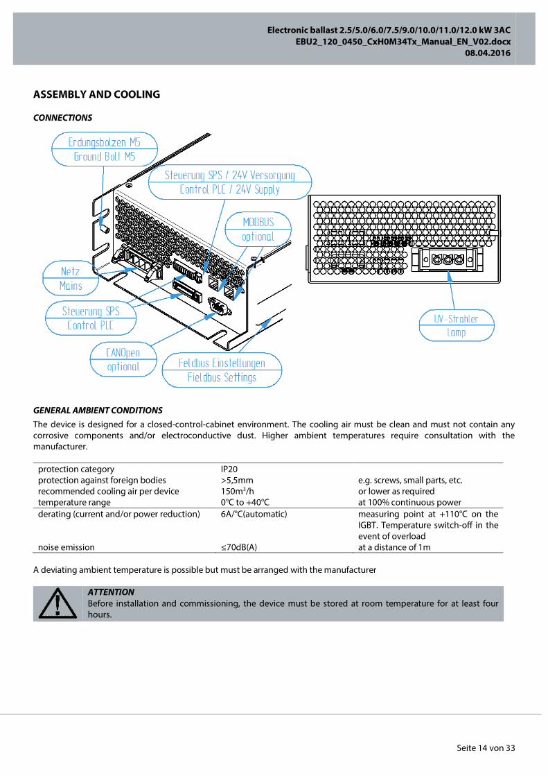
CONNECTIONS
GENERAL AMBIENT CONDITIONS The device is designed for a closed-control-cabinet environment. The cooling air must be clean and must not contain any corrosive components and/or electroconductive dust. Higher ambient temperatures require consultation with the manufacturer.
protection category IP20 protection against foreign bodies >5,5mm e.g. screws, small parts, etc. recommended cooling air per device 150m3/h or lower as required temperature range 0°C to +40°C at 100% continuous power derating (current and/or power reduction) 6A/°C(automatic) measuring point at +110°C on the
IGBT. Temperature switch-off in the event of overload
noise emission ≤70dB(A) at a distance of 1m A deviating ambient temperature is possible but must be arranged with the manufacturer
ATTENTION Before installation and commissioning, the device must be stored at room temperature for at least four hours.
Electronic ballast 2.5/5.0/6.0/7.5/9.0/10.0/11.0/12.0 kW 3AC
EBU2_120_0450_CxH0M34Tx_Manual_EN_V02.docx 08.04.2016
Seite 15 von 33
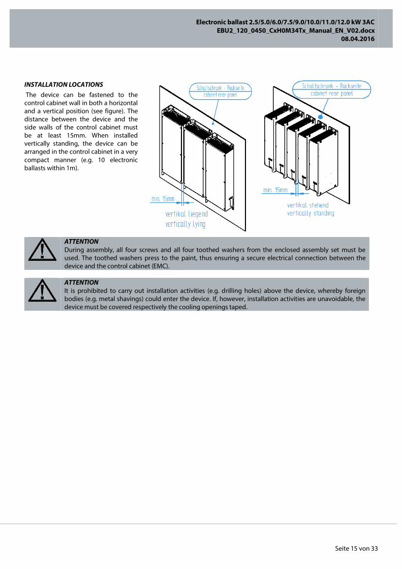
INSTALLATION LOCATIONS The device can be fastened to the control cabinet wall in both a horizontal and a vertical position (see figure). The distance between the device and the side walls of the control cabinet must be at least 15mm. When installed vertically standing, the device can be arranged in the control cabinet in a very compact manner (e.g. 10 electronic ballasts within 1m).
ATTENTION During assembly, all four screws and all four toothed washers from the enclosed assembly set must be used. The toothed washers press to the paint, thus ensuring a secure electrical connection between the device and the control cabinet (EMC).
ATTENTION It is prohibited to carry out installation activities (e.g. drilling holes) above the device, whereby foreign bodies (e.g. metal shavings) could enter the device. If, however, installation activities are unavoidable, the device must be covered respectively the cooling openings taped.

Electronic ballast 2.5/5.0/6.0/7.5/9.0/10.0/11.0/12.0 kW 3AC
EBU2_120_0450_CxH0M34Tx_Manual_EN_V02.docx 08.04.2016
Seite 16 von 33
COOLING The device must preferably be installed in the cool, lower area of the control cabinet. All of the supply air openings must be located underneath the device exhaust air openings. The ventilation direction is marked on the device with an arrow.
ATTENTION The device ventilation direction must be observed. Sufficient cooling cannot be guaranteed if you fail to observe this.
Electronic ballast 2.5/5.0/6.0/7.5/9.0/10.0/11.0/12.0 kW 3AC
EBU2_120_0450_CxH0M34Tx_Manual_EN_V02.docx 08.04.2016
Seite 17 von 33
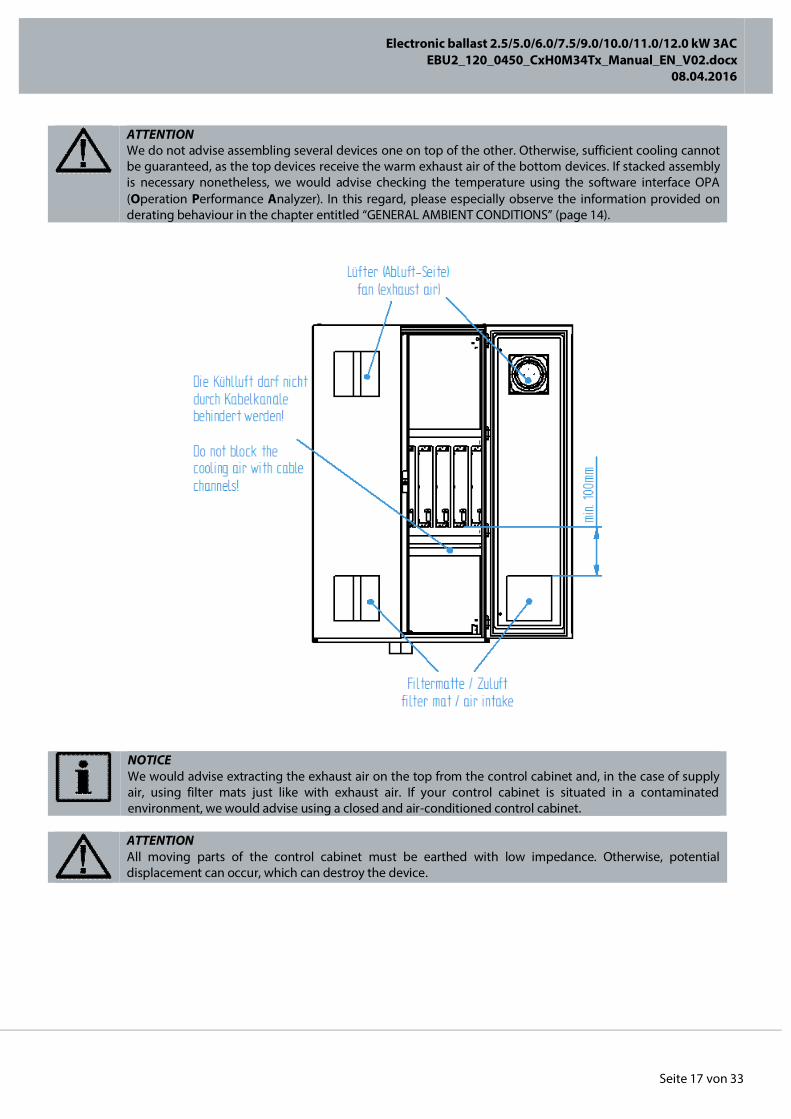
ATTENTION We do not advise assembling several devices one on top of the other. Otherwise, sufficient cooling cannot be guaranteed, as the top devices receive the warm exhaust air of the bottom devices. If stacked assembly is necessary nonetheless, we would advise checking the temperature using the software interface OPA (Operation Performance Analyzer). In this regard, please especially observe the information provided on derating behaviour in the chapter entitled “GENERAL AMBIENT CONDITIONS” (page 14).
NOTICE We would advise extracting the exhaust air on the top from the control cabinet and, in the case of supply air, using filter mats just like with exhaust air. If your control cabinet is situated in a contaminated environment, we would advise using a closed and air-conditioned control cabinet.
ATTENTION All moving parts of the control cabinet must be earthed with low impedance. Otherwise, potential displacement can occur, which can destroy the device.

Electronic ballast 2.5/5.0/6.0/7.5/9.0/10.0/11.0/12.0 kW 3AC
EBU2_120_0450_CxH0M34Tx_Manual_EN_V02.docx 08.04.2016
Seite 18 von 33
ATTENTION The cooling flow must not be blocked (e.g. by cable ducts) on the devices supply air opening or exhaust air opening. Otherwise, sufficient cooling cannot be guaranteed.
Electronic ballast 2.5/5.0/6.0/7.5/9.0/10.0/11.0/12.0 kW 3AC
EBU2_120_0450_CxH0M34Tx_Manual_EN_V02.docx 08.04.2016
Seite 19 von 33
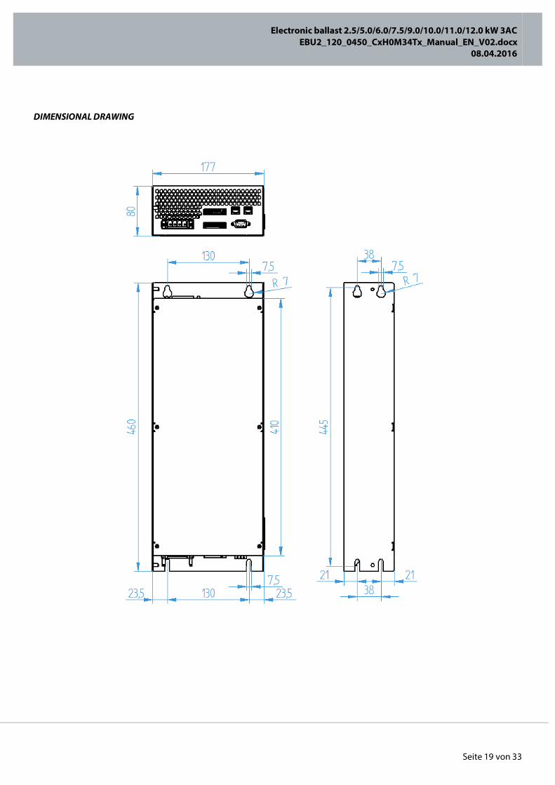
DIMENSIONAL DRAWING
Electronic ballast 2.5/5.0/6.0/7.5/9.0/10.0/11.0/12.0 kW 3AC
EBU2_120_0450_CxH0M34Tx_Manual_EN_V02.docx 08.04.2016
Seite 20 von 33
ELECTRICAL INSTALLATION
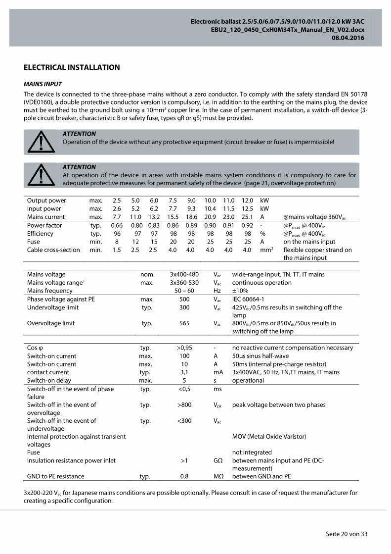
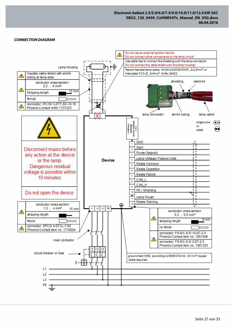
MAINS INPUT The device is connected to the three-phase mains without a zero conductor. To comply with the safety standard EN 50178 (VDE0160), a double protective conductor version is compulsory, i.e. in addition to the earthing on the mains plug, the device must be earthed to the ground bolt using a 10mm2 copper line. In the case of permanent installation, a switch-off device (3-pole circuit breaker, characteristic B or safety fuse, types gR or gS) must be provided.
ATTENTION Operation of the device without any protective equipment (circuit breaker or fuse) is impermissible!
ATTENTION At operation of the device in areas with instable mains system conditions it is compulsory to care for adequate protective measures for permanent safety of the device. (page 21, overvoltage protection)
Output power max. 2.5 5.0 6.0 7.5 9.0 10.0 11.0 12.0 kW Input power max. 2.6 5.2 6.2 7.7 9.3 10.4 11.5 12.5 kW Mains current max. 7.7 11.0 13.2 15.5 18.6 20.9 23.0 25.1 A @mains voltage 360Vac Power factor typ. 0.66 0.80 0.83 0.86 0.89 0.90 0.91 0.92 - @Pmax @ 400Vac Efficiency typ. 96 97 97 98 98 98 98 98 % @Pmax @ 400Vac Fuse min. 8 12 15 20 20 25 25 25 A on the mains input Cable cross-section min. 1.5 2.5 2.5 4.0 4.0 4.0 4.0 4.0 mm2 flexible copper strand on
the mains input
Mains voltage nom. 3x400-480 Vac wide-range input, TN, TT, IT mains Mains voltage range1 max. 3x360-530 Vac continuous operation Mains frequency 50 – 60 Hz ±10% Phase voltage against PE max. 500 Vac IEC 60664-1 Undervoltage limit typ. 300 Vac 425Vdc/0.5ms results in switching off the
lamp Overvoltage limit typ. 565 Vac 800Vdc/0.5ms or 850Vdc/50us results in
switching off the lamp
Cos φ typ. >0,95 - no reactive current compensation necessary Switch-on current max. 100 A 50µs sinus half-wave Switch-on current max. 10 A 50ms (internal pre-charge resistor) contact current typ. 3,1 mA 3x400VAC, 50 Hz, TN,TT mains, IT mains Switch-on delay max. 5 s operational Switch-off in the event of phase failure
typ. <0,5 ms
Switch-off in the event of overvoltage
typ. >800 Vpk peak voltage between two phases
Switch-off in the event of undervoltage
typ. <300 Vac
Internal protection against transient voltages
MOV (Metal Oxide Varistor)
Fuse not integrated Insulation resistance power inlet >1 GΩ between mains input and PE (DC-
measurement) GND to PE resistance typ. 0.8 MΩ between GND and PE
3x200-220 Vac for Japanese mains conditions are possible optionally. Please consult in case of request the manufacturer for creating a specific configuration.

Electronic ballast 2.5/5.0/6.0/7.5/9.0/10.0/11.0/12.0 kW 3AC
EBU2_120_0450_CxH0M34Tx_Manual_EN_V02.docx 08.04.2016
Seite 21 von 33
If a device is not working at the maximum power (e.g. a 5kW device with a 3kW lamp), the mains current can be determined with the help of the following diagram. This enables considerable cross-section and cost savings to be made when several devices are used in line.
NOTICE Further installation notices can be found in the chapter entitled “Connection diagram” (page 27).
ATTENTION All moving parts of the control cabinet must be earthed with low impedance. Otherwise, potential displacement can occur, which can destroy the device.
OVERVOLTAGE PROTECTION We would advise using overvoltage protectors to optimally protect the device. The use of a suitable varistor module plus an appropriate voltage monitoring relay ensures best possible safety for the device. To select the ideal types, please contact the manufacturer with precise information about the relevant mains (TN, TT, IT, etc.) and the prevalent mains voltage. Recommended minimum device protection for TN- and TT-main systems is following type or equivalent part:
Varistormodul (Phoenix Contact VAL-MS 320/3+0-FM, Art. Nr. 2920243) o Protection level: 1,5kV (Phases to PE) o Quantity: 1 piece per control cabinet o Cable length: max. 50cm
For IT-main systems may a higher protection level need to be considered. .
ATTENTION Consider the local installation requirements!
ATTENTION When operating several devices, we would advise switching the devices on or off in staggered time intervals of 2 seconds to avoid high switch-on currents during switch-on operations or switching surges during switch-off operations.

Electronic ballast 2.5/5.0/6.0/7.5/9.0/10.0/11.0/12.0 kW 3AC
EBU2_120_0450_CxH0M34Tx_Manual_EN_V02.docx 08.04.2016
Seite 22 von 33
LAMP OUTPUT
DANGER When working on the lamp output, the device must be disconnected from the mains and a waiting time of at least 10 minutes complied with! Observe the safety notices contained in the chapter entitled “Safety notices” (page 8)!
The device allows lamp cable lengths of up to 300m. The lamp output of the device is designed to be resistent against short-circuit, open-circuit operation and earth leakage. Several lamps can be connected in series. The lamp currents and the required cable cross-sections are illustrated in the following table.
Output power from 5% to 100% stepless dimmable Power accuracy typ. +3/-3 % @nominal power Control settling time typ. <3 ms Frequency 50 Hz or parameterisable after consultation
with the manufacturer Lamp voltage max. 450 V symm. square-wave voltage
@3x360VAC Lamp voltage
max.
585 V
symm. Square-wave voltage @3x480VAC
Lamp current max. 22.0 /28.5 A parameterisable 1.) only in the case of a 10,0/11,0/12,0kW device Max. 22.0 @480VAC
Minimum lamp current typ. 2,0 A parameterisable Direct current offset max. 100 mA Cable length max. 300 m shielding recommended Cable cross-section min. up to 15A: 2,5; from 15A 4,0 mm2 lamp side, flexible
Ignition voltage typ. 5 kV sinusoidal Ignition frequency typ. 20 kHz Ignition duration max. 1000 ms ignition lock; 5 sec.
Short-circuit identification on lamp typ. 20 V deactivates for 2 min. after lamp start Minimum lamp voltage typ. 50 V switch-off in the event of a shortfall of >1
sec. Earth leakage triggering threshold typ. 12,5 A no personal protection Earth leakage response time typ. 50 µs switch-off following ground leakage in the
lamp curcuit Connect the cable shield on the lamp side to the metal lug of the lamp plug using cable ties and insulate with a shrink hose! Installation between the device and lamp must be configured to at least 5kV due to the high ignition voltage. Between the lamp lines and the signal lines, comply with a safety distance of at least 5cm to avoid probable interference. No other parts must be earthed via the lamp cable. Under no circumstances must the lamp housing be earthed via the lamp line shielding, which is why a separate cable must be used for earthing. The device has an internal ignitor and under no circumstances must an external ignitor of other components (measuring devices, etc.) be connected.
NOTICE The lamp cable must be laid in a cable duct. Loose installation is not permissible.
NOTICE Under no circumstances must the lamp cable be laid in a cable duct together with the power cord and/or control cable.

Electronic ballast 2.5/5.0/6.0/7.5/9.0/10.0/11.0/12.0 kW 3AC
EBU2_120_0450_CxH0M34Tx_Manual_EN_V02.docx 08.04.2016
Seite 23 von 33
NOTICE To ensure that the shield is connected, both screws on the lamp connector must be tightened professionally.
NOTICE Further installation notices can be found in the chapter entitled “Connection diagram” (page 27).
Electronic ballast 2.5/5.0/6.0/7.5/9.0/10.0/11.0/12.0 kW 3AC
EBU2_120_0450_CxH0M34Tx_Manual_EN_V02.docx 08.04.2016
Seite 24 von 33
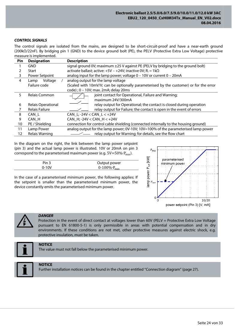
CONTROL SIGNALS The control signals are isolated from the mains, are designed to be short-circuit-proof and have a near-earth ground (200kΩ/22nF). By bridging pin 1 (GND) to the device ground bolt (PE), the PELV (Protective Extra Low Voltage) protective measure is implemented.
Pin Designation Description 1 GND signal ground 0V; maximum ±25 V against PE (PELV by bridging to the ground bolt) 2 Start activate ballast; active: +5V – +24V; inactive 0V; Ri = 1kΩ 3 Power Setpoint analog input for the lamp power; voltage 0 – 10V or current 0 – 20mA 4 Lamp Voltage /
Failure code analog output for the lamp voltage (Scaled with 10mV/V; can be optionally parameterised by the customer) or for the error code) ; 0 – 10V; max. 2mA; delay 20ms
5 Relais Common joint contact for Operational, Failure and Warning; maximum 24V/300mA
6 Relais Operational relay output for Operational; the contact is closed during operation 7 Relais Failure relay output for Failure; the contact is open in the event of errors 8 CAN_L CAN_L; -24V < CAN_L < +24V 9 CAN_H CAN_H; -24V < CAN_H < +24V
10 PE / Shielding connection for control cable shielding (connected internally to the housing ground) 11 Lamp Power analog output for the lamp power; 0V-10V; 10V=100% of the parameterised lamp power 12 Relais Warning relay output for Warning; for details, see the flow chart
In the diagram on the right, the link between the lamp power setpoint (pin 3) and the actual lamp power is illustrated. 10V or 20mA on pin 3 correspond to the parameterised maximum power (e.g. 5V=50%∙Pmax).
Pin 3 Output power 0-10V 0-100%∙Pmax
In the case of a parameterised minimum power, the following applies: If the setpoint is smaller than the parameterised minimum power, the device constantly emits the parameterised minimum power.
DANGER Protection in the event of direct contact at voltages lower than 60V (PELV = Protective Extra Low Voltage pursuant to EN 61800-5-1) is only permissible in areas with potential compensation and in dry environments. If these conditions are not met, other protective measures against electric shock, e.g. protective insulation, must be taken.
NOTICE The value must not fall below the parameterised minimum power.
NOTICE Further installation notices can be found in the chapter entitled “Connection diagram” (page 27).

Electronic ballast 2.5/5.0/6.0/7.5/9.0/10.0/11.0/12.0 kW 3AC
EBU2_120_0450_CxH0M34Tx_Manual_EN_V02.docx 08.04.2016
Seite 25 von 33
SAMPLE CONNECTION FOR MINIMUM SIGNAL CIRCUITRY
SAMPLE CONNECTION OF ANALOG PLC CONNECTION
Electronic ballast 2.5/5.0/6.0/7.5/9.0/10.0/11.0/12.0 kW 3AC
EBU2_120_0450_CxH0M34Tx_Manual_EN_V02.docx 08.04.2016
Seite 26 von 33
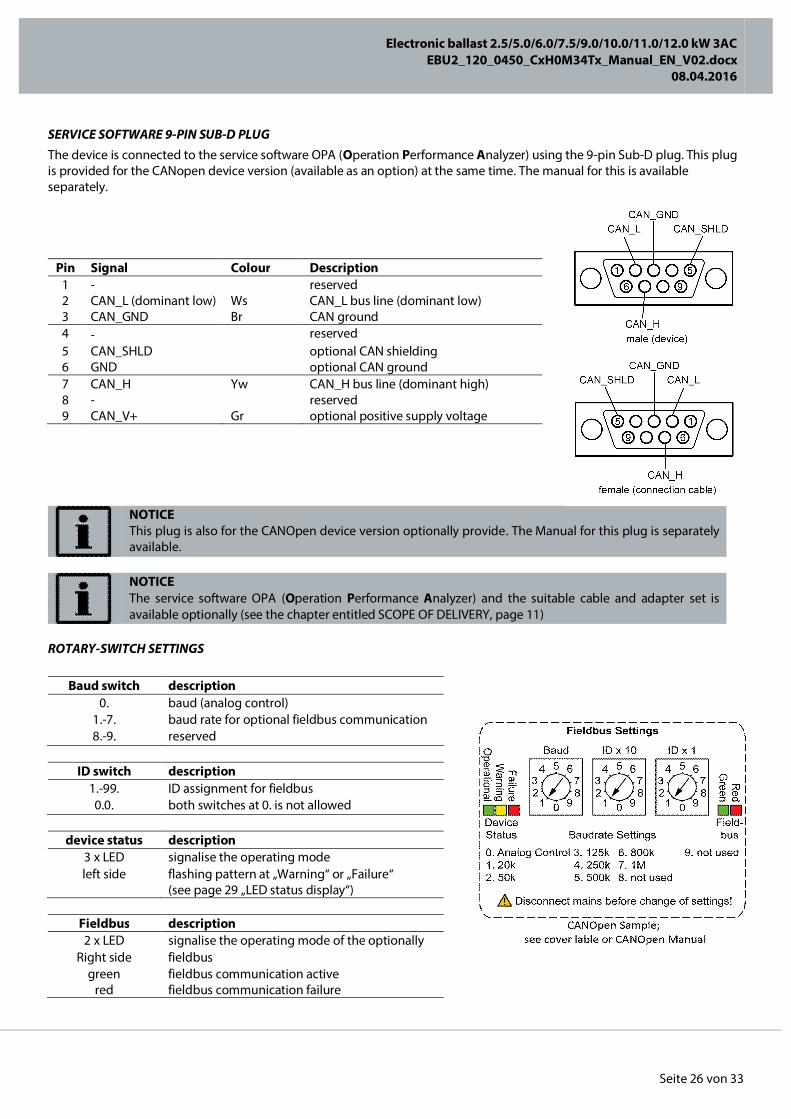
SERVICE SOFTWARE 9-PIN SUB-D PLUG The device is connected to the service software OPA (Operation Performance Analyzer) using the 9-pin Sub-D plug. This plug is provided for the CANopen device version (available as an option) at the same time. The manual for this is available separately.
NOTICE This plug is also for the CANOpen device version optionally provide. The Manual for this plug is separately available.
NOTICE The service software OPA (Operation Performance Analyzer) and the suitable cable and adapter set is available optionally (see the chapter entitled SCOPE OF DELIVERY, page 11)
ROTARY-SWITCH SETTINGS
Baud switch description 0. baud (analog control)
1.-7. baud rate for optional fieldbus communication 8.-9. reserved
ID switch description
1.-99. ID assignment for fieldbus 0.0. both switches at 0. is not allowed
device status description
3 x LED signalise the operating mode left side flashing pattern at „Warning“ or „Failure“
(see page 29 „LED status display“)
Fieldbus description 2 x LED signalise the operating mode of the optionally
Right side fieldbus green
red fieldbus communication active fieldbus communication failure
Pin Signal Colour Description 1 - reserved 2 CAN_L (dominant low) Ws CAN_L bus line (dominant low) 3 CAN_GND Br CAN ground 4 - reserved 5 CAN_SHLD optional CAN shielding 6 GND optional CAN ground 7 CAN_H Yw CAN_H bus line (dominant high) 8 - reserved 9 CAN_V+ Gr optional positive supply voltage
Electronic ballast 2.5/5.0/6.0/7.5/9.0/10.0/11.0/12.0 kW 3AC
EBU2_120_0450_CxH0M34Tx_Manual_EN_V02.docx 08.04.2016
Seite 27 von 33
CONNECTION DIAGRAM
Electronic ballast 2.5/5.0/6.0/7.5/9.0/10.0/11.0/12.0 kW 3AC
EBU2_120_0450_CxH0M34Tx_Manual_EN_V02.docx 08.04.2016
Seite 28 von 33
OPERATING BEHAVIOUR, FUNCTIONAL DESCRIPTION
“READY” OPERATING MODE After connecting the mains connector, the device is in the “Ready” operating mode and the lamp is deactivated. The aim of this mode is to initiate the ignition process and power up the lamp to the parameterised power. Within the first 5 seconds, internal device capacitors are gently charged up and the firmware is initialised. Afterwards, the device waits until the ignition process is started by pin 2 on the signal connector (“Start”) with a voltage of +5 – +24V. Optionally the start process can also be initiated using the power setpoint.
NOTICE Pin 2 on the signal connector is edge-triggered and conducted with a Schmitt trigger input.
If ignition has not taken place within one second, the device enters “Failure” operating mode. Once ignition has successfully taken place, the lamp is powered up to 100% of the parameterised power as quickly as possible using the device’s own lamp management. The warm-up current can be adjusted separately during this process. Normally, the maximum available warm-up current is permitted so the lamp powers up as quickly as possible. In special cases, a reduced warm-up current is possible so that damages to the sensitive lamps are avoided. During the lamp power-up process, pin 4, which has a dual function (“Lamp voltage” when operational / “Failure code” in the event of error), indicate the scaled lamp voltage (scaling factor of 10mV/V) (e.g. 4,5 V correspond to a lamp voltage of 450V). The lamp voltage can thus be monitored and visualised with ease during the power-up process.
“OPERATIONAL” OPERATING MODE Once the parameterised maximum lamp power has been reached, the device directly switches to “Operational” operating mode. This is indicated by means of the “Operational” relay contact (pin 5 “Common” and pin 6 “Operational” on the signal connector). From this point in time, the device regulates on the power setpoint, which is allocated using pin 3 of the signal connector (“Power Setpoint”). The setpoint can be specified as a voltage value (0 - 10V) or as a current value (0 – 20mA). The requested and output powers are constantly compared within this operating mode.
“WARNING” OPERATING MODE If the required power was not met within the last one second, a warning is issued on pin 4. In event of power deviations of less than 20%, permanent operation with reduced production speed is possible (e.g. in a reel application to complete the current production order). A deviation of more than 20% to the power setpoint causes the device to switch to “Failure” operating mode. The “Warning” relay (pin 12) enables early identification and intervention in case if the power setpoint should deviate from real lamp power.
“FAILURE” OPERATING MODE The device is designed to be intrinsically safe and has a multitude of monitoring functions integrated that protect the device in extreme situations (e.g. in the event of an overvoltage) and result in the safe “Failure” operating mode. During this process, the “Failure” relay contact (pin 5 “Common” and pin 7 “Failure” on the signal connector) opens and enables immediate failure identification in the superordinate production process. The lamp is deactivated and the device thus remains in this condition until the user restarts it.
NOTICE To identify the error type (e.g. lamp short-circuit, etc.), it is necessary to read the analog voltage of pin 4 right after the error has been identified. Otherwise, the information about the cause of the error is lost.
In the case of an internal error, the device must be returned to the manufacturer for checking purposes. In the event of the other sources of error, pin 2 must be deactivated and a waiting time of 5 seconds complied with before the ballast is restarted with a renewed edge on pin 2.

Electronic ballast 2.5/5.0/6.0/7.5/9.0/10.0/11.0/12.0 kW 3AC
EBU2_120_0450_CxH0M34Tx_Manual_EN_V02.docx 08.04.2016
Seite 29 von 33
FLOW CHART
Electronic ballast 2.5/5.0/6.0/7.5/9.0/10.0/11.0/12.0 kW 3AC
EBU2_120_0450_CxH0M34Tx_Manual_EN_V02.docx 08.04.2016
Seite 30 von 33
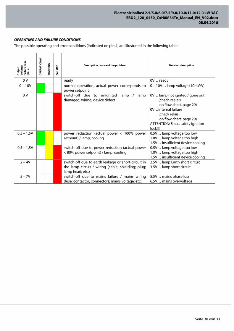
OPERATING AND FAILURE CONDITIONS The possible operating and error conditions (indicated on pin 4) are illustrated in the following table.
Out
put
Vol
tage
/ Fa
ilure
co
de
(Pin
4)
OPE
RATI
ON
AL
WA
RNIN
G
FAIL
URE
Description / cause of the problem Detailed description
0 V ready 0V… ready 0 – 10V normal operation; actual power corresponds to
power setpoint 0 – 10V… lamp voltage (10mV/V)
0 V
switch-off due to unignited lamp / lamp damaged; wiring; device defect
0V… lamp not ignited / gone out (chech realais on flow chart, page 29) 0V…internal failure (check relais on flow chart, page 29) ATTENTION: 5 sec. safety ignition lock!!!
0,5 – 1,5V
power reduction (actual power < 100% power setpoint) / lamp, cooling
0.5V… lamp voltage too low 1.0V… lamp voltage too high 1.5V… insufficient device cooling
0,5 – 1,5V
switch-off due to power reduction (actual power < 80% power setpoint) / lamp; cooling
0.5V… lamp voltage too low 1.0V… lamp voltage too high 1.5V… insufficient device cooling
2 – 4V
switch-off due to earth leakage or short-circuit in the lamp circuit / wiring (cable; shielding; plug; lamp head; etc.)
2.5V… lamp Earth short circuit 3.5V… lamp short circuit
5 – 7V switch-off due to mains failure / mains wiring (fuse; contactor; connectors; mains voltage; etc.)
5.5V… mains phase loss 6.5V… mains overvoltage
Electronic ballast 2.5/5.0/6.0/7.5/9.0/10.0/11.0/12.0 kW 3AC
EBU2_120_0450_CxH0M34Tx_Manual_EN_V02.docx 08.04.2016
Seite 31 von 33
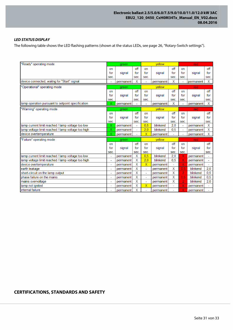
LED STATUS DISPLAY The following table shows the LED flashing patterns (shown at the status LEDs, see page 26, “Rotary-Switch settings”).
CERTIFICATIONS, STANDARDS AND SAFETY
Electronic ballast 2.5/5.0/6.0/7.5/9.0/10.0/11.0/12.0 kW 3AC
EBU2_120_0450_CxH0M34Tx_Manual_EN_V02.docx 08.04.2016
Seite 32 von 33
Every device was carefully crafted and tested under the guidelines of the CE declaration of conformity. Details can be taken from the CE declaration of conformity.
LEGAL NOTICE All rights reserved © Copyright by PowerUnits Leistungselektronik GmbH Millennium Park 5 6890 Lustenau Austria Publisher responsible for the content: PowerUnits Leistungselektronik GmbH Layout: PowerUnits Leistungselektronik GmbH Disclaimer: The utmost care was exercised while creating this instruction manual. However, errors cannot be excluded in spite of this. No guarantee is given with regard to data and information. This instruction manual must not be reproduced – whether in whole or in part – without the written consent of PowerUnits Leistungselektronik. We expressly reserve the right to make technical changes with a view to improving the device described or increasing the safety standard – even without giving separate notice.