Embed Size (px)
Citation preview
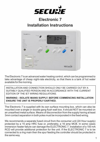
Electronic 7
Installation Instructions
The Electronic 7 is an advanced water heating control, which can be programmed to take advantage of cheap night-rate electricity, so that there is a tank of hot water available for the morning.
1
WARNING : ISOLATE MAINS SUPPLY. BEFORE COMMENCING INSTALLATION ENSURE THE UNIT IS PROPERLY EARTHED.
INSTALLATION AND CONNECTION SHOULD ONLY BE CARRIED OUT BY A SUITABLY QUALIFIED PERSON AND IN ACCORDANCE WITH THE CURRENT EDITION OF THE IET WIRING REGULATIONS.
The Electronic 7 is supplied with its own surface mounting box, which can also be mounted over a single or double gang flush wall box. It should NOT be mounted on an unearthed metal surface. Means of disconnection from the supply having at least 3mm contact separation in both poles must be incorporated in the fixed wiring.
We recommends a separate fused circuit from the consumer unit (24 Hour supply) protected by a 15 amp HRC fuse or, preferably, a 16 amp MCB. In some cases immersion heater failure can damage the ELECTRONIC 7. Installation of a 100 mA RCD will provide additional protection for the unit. If the ELECTRONIC 7 is to be connected to a ring main then the spur feeding the controller should be protected in the same way.

The Electronic 7 should be removed from the mounting box by unscrewing the 2 captive screws securing the unit.
Mounting
Use either holes marked 'A' in Fig.1 to secure to a single gang box, or the two holes marked 'C' for a double gang box. Cable entry is through the cut-out between the 2 fixing holes 'A'.
Use the two holes marked 'B' in Fig. 1 Cable entry is through the most appropriate cut-out
Surface Mounting
Conduit Box Mounting
REMOVE THE APPROPRIATE CABLE ENTRY CUT-OUTS BEFORE FIXING THE BOX, WHERE POSSIBLE DRILL THE BOX TO PROVIDE A CLOSE FITTING ENTRY FOR CABLES AND HEAT-RESISTANT FLEXIBLE CORDS. TAKE CARE TO REMOVE SHARP EDGES .
TERMINAL 4 - LIVE out to Boost immersion heater
TERMINAL 3 - NEUTRAL(s) out to immersion heater(s)
TERMINAL 1 - LIVE in
Use a three-core cable with a minimum conductor size of 1.0mm for a 2kW heater, or 1.5mm for a 3kW heater to connect the unit to the supply. Connect the incoming wires to the terminal block as follows;
Connections
TERMINAL 2 - NEUTRAL in
TERMINAL 5 - LIVE out to Off-Peak immersion heater
Clamp all surface wiring adjacent to the box or use trunking where appropriate. Secure the heat resistant flexible cords from the immersion heaters using the cable clamp in the box.
Link terminals 4 & 5 when using a single immersion heater
2

Dual Element Immersion Heaters
TERMINAL 4 (Boost live output) should be connected to TERMINAL 5 (Off-Peak live output) and to the immersion heater.
Single Element Immersion Heaters
The 3 core flexible cord should be heat-resistant and rated to 85°C.
The Neutral connection should go to TERMINAL 3 and the Earth connection to the EARTH TERMINALS.
The Neutral connections should go to TERMINAL 3 and the Earth connection to the EARTH TERMINALS.
The thermostat for the top immersion element should be set lower than the thermostat for the bottom immersion heater.
TERMINAL 4 (boost live output) should be connected to the short element and TERMINAL 5 (Off-Peak live output) to the long element.
Twin Immersion Heaters
The 3 core flexible cords should be heat-resistant and rated 85ºC. TERMINAL 4 (boost live output) should be connected to the top immersion heater and TERMINAL 5 (off-peak live output) to the bottom immersion heater. The two Neutral connections should go to TERMINAL 3 and the Earth connections to the EARTH TERMINALS.
When wiring is complete ensure that all terminal screws, including the earth terminal screws are securely tightened to achieve a minimum torque of .75Nm.
Commissioning Instructions
The elements should be controlled through separate thermostats. In practice the thermostat for the top (short) element is usually set 5-10°C less than the thermostat for the long Off-Peak element. The 3 core flexible cords should be heat-resistant and rated 85°C.
3
The commissioning switch is on the rear of the unit (once removed from the back box) and must now be set to achieve the correct operation of the controller and to engage the BATTERY RESERVE. The display will remain blank with the switch in the “OFF” position.
It is essential that the correct commissioning switch position is selected. Incorrect setting of the commissioning switch may result in inefficient use of the available off-peak supply. On installation the installer needs to select whether the Electronic 7 will switch at GMT times throughout the year or whether the timings need to alter as the clocks change.
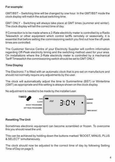
The Electronic 7 is fitted with an automatic clock that is pre-set on manufacture and should not normally require any adjustments by the user.
No adjustment is needed to be made by the installer/user.
Time Display
The clock will automatically adjust the time to Summertime (BST) or Wintertime (GMT) as appropriate and this setting is always shown on the clock display.
GMT/BST – Switching time will be changed by one hour. In the GMT/BST mode the clock display will match the actual switching time.
GMT ONLY – Switching will always take place at GMT times (summer and winter). The clock display will tell the correct time of day.
If Connection is to be made where a 2-Rate electricity meter is controlled by a Radio Teleswitch or other equipment which control tariffs remotely or seasonally, it is essential that before setting the commissioning switch you find out how the off-peak times are controlled.
The Customer Service Centre of your Electricity Supplier will confirm information regarding Off-Peak electricity timing and the switching method used for your area. On installations where the 2-Rate electricity meter is controlled by a mechanical Tariff Timeswitch the commissioning switch should be set to GMT ONLY.
For example:
TIMEDRUN SUMMER
WINTER
TIMED BOOST
CLOCK
BOOST PROGRAMME
OFF PEAK PROGRAMME
AM
Resetting The Unit
Sometimes electronic equipment can become scrambled or frozen. To overcome this you should reset the unit.
The clock should now be adjusted to the correct time of day by following Setting Time of Day on page 5.
This can be achieved by holding down the buttons marked “BOOST, MINUS, PLUS & SELECT” simultaneously.
4

Press the green “SET” button until the indicator on the left hand side of the screen is next to “CLOCK”.
Setting Time of Day
Adjust the hour by pressingthe white “MINUS” or “PLUS” buttons. Once you are happy with the hour selected, press the blue “SELECT” button.
The minutes will now flash. To adjust the minutes you need to once again press the “MINUS” or “PLUS” buttons.
Once you are happy with the time selected, press the blue “SELECT” button, this will now take it back to the “RUN” position on the left hand side of the screen.
Setting Off-Peak Heating Periods
Press the green SET button until the indicator on the left hand side of the screen is next to “OFF PEAK PROGRAMME”
The hour will now flash for the 1st on time, this can be adjusted by pressing the “MINUS” and “PLUS” buttons. Once you are happy with the hour you have selected press the “SELECT” button
This will then make the minutes flash, which can be adjusted by pressing the “MINUS” and “PLUS” buttons as required. Once you are happy with the minutes, press the “SELECT” button to take you to the 1st off time
Use the “MINUS” and “PLUS” buttons to adjust the hour. When you are happy with the hour selected then press the “SELECT” button which shall now take you to the minutes. Press the “MINUS” and “PLUS” buttons to SELECT the minutes you require and once you are happy with the minutes press the “SELECT” button.
flashing on the 2nd on time, if this is not required then pressthe green “SET” button which will take you back to the main screen.
The hour will be
If your electricity tariff offers multiple off peak periods then the 2nd and 3rd off peak periods should be set up by repeating the above procedure. Should you not require any further off-peak settings ensure that the remaining periods are set at the same time. For example; 2nd On 12:00am - 2nd Off 12:00am; 3rd On 12:00am - 3rd Off 12:00am (These are de-fault settings).
5

Default Time Settings
Default Times
1st ON 1st OFF 2nd ON 2nd OFF 3rd ON 3rd OFF
2:15am 7:15am 12:00am 12:00am 12:00am 12:00am
To assemble the controller to its mounting box, first push the connectors numbered 1-5 into the corresponding numbered terminal as shown in Fig.1
Questions
(A) The back-up battery is integral to the unit and will save the settings for at least two years if the power is disconnected. The battery is NOT replaceable and any attempt to remove it will invalidate the warranty.
After re-setting the unit the off-peak heating times will revert back to the default factory settings, these are shown above, however if you wish to change these times please proceed as instructed in the SETTING OFF-PEAK HEATINGS PERIODS part of this manual on page 5.
Completing The Installation
Switch on the mains supply and put the rocker switch in the TIMED position.
Note: These are the default settings assuming the immersion heater is ON only during the night hours and OFF during daytime hours.
Carefully offer the controller to the box and secure with the fixing screws, ensuring the wiring does not become damaged.
(Q) There is no display on the screen?(A) Ensure there is mains supply getting to the unit and that the battery switch on the rear of the unit is in either the GMT / BST or GMT ONLY position.
(Q) The display has become frozen?(A) This could be due to local electrical interference. Using the RESET procedure in this manual may rectify the fault.
(Q) How do I change the back-up battery?
6

BS EN 60720-2-7, BEAB Approved
RoHS
Specification
Electrical
Purpose of Control Electronic Immersion Heater Control for E7
Tariffs
Contact Rating 13A Amp 230V AC
(Suitable for Emmersion Heaters up to 3kW)
Contact Type Micro-disconnection
Switch Type Rocker switch, double-pole micro-disconnection
Supply 230V AC 50Hz only
Protection Class I
Control Action Type 1B,R
Operating Time Limitation Intermittent
Software Class Class A
Battery Type Lithium
Battery Life 2 Years
Display Custom LCD, Backlit
Clock 12 hour AM/PM
Display Time Adjustment 1 Minute Intervals
Switch Time Adjustment 1 Minute Steps
Programme Selection Off-Peak, 3 periods per day.
Programmable Boost & 1 Hour Manual Boost
Environmental
Impulse Voltage Rating Cat III 4000V
Enclosure Protection Ip30
Pollution Degree Degree 2o oOperating Temperature Range 0 C to +35 C
Compliance
Design Standard EN 60730-2-7, BS EN 60730-1,
Mechanical
Dimensions 170mm x 115mm x 60mm
Case Material Thermoplastic, flame retardantoBall Pressure Test Temperature 75 C
Mounting Custom surface mounted back
box,.Independantly mounted
7

Part Number P83080 Issue 8
NP0 0 8 3 0 8 0 0 0 0Chandler's Ford,Secure House, Lulworth Close,
Eastleigh, SO53 3TL, UKt: +44 1962 840048 f: +44 1962 841046
Secure Meters (UK) Ltd
www.securemeters.com