Embed Size (px)
Citation preview
Electron Guns
Fall, 2017
Kyoung-Jae Chung
Department of Nuclear Engineering
Seoul National University

2/20 Radiation Source Engineering, Fall 2017
Pierce method for gun design
The first step in the charged-particle acceleration process is to extract low-energy particles from a source and to form them into a beam. The particle source and initial acceleration gaps constitute the injector. The particles move slowly in the first acceleration gap, and the space-charge forces are correspondingly strong.
The analytic derivation of Pierce gives a self-consistent solution for a space-charge dominated injector. The procedure predicts the shapes of accelerating electrodes to produce a laminar beam with uniform current density.
Although the treatment holds only for the special geometry of a sheet beam accelerated through an extraction grid, it gives valuable insights into the design of more complex guns.
Assumptions:• A space-charge-limited injector creates a sheet beam of width ±𝑥𝑥0.• Particle motion in the extraction gap is non-relativistic.• The force from beam-generated magnetic fields is small.• Potentials at the surface and extractor electrodes are determined by
conducting surfaces—the beam exits the gap through a grid or foil.

3/20 Radiation Source Engineering, Fall 2017
[Remind] Potential distribution across a gap for space-charge-limited ion flow Space-charge-limited current in a plane diode
𝐽𝐽0 =49𝜖𝜖0
2𝑒𝑒𝑀𝑀
1/2 𝑉𝑉03/2
𝑑𝑑2
Potential distribution within the gap
𝜙𝜙 𝑧𝑧 = −𝑉𝑉0𝑧𝑧𝑑𝑑
4/3
Electric field distribution within the gap
𝐸𝐸 =43𝑉𝑉0𝑑𝑑
𝑧𝑧𝑑𝑑
1/3

4/20 Radiation Source Engineering, Fall 2017
Pierce extraction system
The essential principle of a Pierce extraction system is that the effect of the particles external to the chosen region can be represented by means of a single unipotential electrode, called the beam-forming or focusing electrode.
This electrode should cause the field in the region external to the beam satisfy the proper boundary conditions at the beam edge, i.e. the transverse electric field is zero everywhere at the beam edge and the electric potential along the beam boundary is the same as in the corresponding idealized SCL diode.
𝜙𝜙(0,𝑦𝑦, 𝑧𝑧) = 𝑉𝑉0𝑧𝑧𝑑𝑑
4/3
𝜕𝜕𝜙𝜙𝜕𝜕𝑥𝑥 = 0

5/20 Radiation Source Engineering, Fall 2017
Pierce extraction system
The desired potential distribution external to the beam is given by
In principle, the desired potential distribution in the region external to the beam will be completely determined by two properly formed electrodes: the focusing electrode and the extraction electrode.
𝜙𝜙(𝑥𝑥, 𝑧𝑧) =𝑉𝑉0𝑑𝑑 ⁄4 3 𝑥𝑥2 + 𝑧𝑧2 ⁄2 3 cos
43
tan−1𝑥𝑥𝑧𝑧
𝜙𝜙1 𝑥𝑥, 𝑧𝑧 = 0
𝜙𝜙 = 0 𝜙𝜙 = 𝑉𝑉0
𝜙𝜙2 𝑥𝑥, 𝑧𝑧 = 𝑉𝑉0
43 tan−1
𝑥𝑥𝑧𝑧 =
𝜋𝜋2
𝑥𝑥 = 𝑧𝑧 tan3𝜋𝜋8
67.5°
1𝑑𝑑 ⁄4 3 𝑥𝑥2 + 𝑧𝑧2 ⁄2 3 cos
43 tan−1
𝑥𝑥𝑧𝑧 = 1
𝜙𝜙1 𝜙𝜙2
Very complex

6/20 Radiation Source Engineering, Fall 2017
Geometry of planar Pierce extraction system
𝑥𝑥 = 𝑧𝑧 tan3𝜋𝜋8
1𝑑𝑑 ⁄4 3 𝑥𝑥2 + 𝑧𝑧2 ⁄2 3 cos
43 tan−1
𝑥𝑥𝑧𝑧 = 1

7/20 Radiation Source Engineering, Fall 2017
Axisymmetric Pierce extraction system
Many applications require cylindrical electron beams. The design of a cylindrical gun follows the same procedure as a sheet beam gun. We can apply numerical methods to search for cylindrical electrode shapes that give the variation of potential along a beam boundary at 𝑟𝑟𝑜𝑜:
In this case, the zero potential surface (focusing electrode) is a conical curved surface having a gradually increasing angle with the emission electrode from 67.5° to 74.16°.
𝜙𝜙(𝑟𝑟𝑜𝑜, 𝑧𝑧) = 𝑉𝑉0 ⁄𝑧𝑧 𝑑𝑑 4/3
Increasing axial electric field
1𝑟𝑟𝜕𝜕𝜕𝜕𝑟𝑟
𝑟𝑟𝐸𝐸𝑟𝑟 +𝜕𝜕𝐸𝐸𝑧𝑧𝜕𝜕𝑧𝑧
= 0Radial electric field:

8/20 Radiation Source Engineering, Fall 2017
Distortion of electric field due to anode aperture
In the previous analyses, we ignored the effects of an anode aperture. In most cases, however, an anode aperture modifies the electric fields in an electron gun.
The radial electric fields defocus exiting electrons. The fields act like an electrostatic lens with negative focal length—the defocusing action is called the negative lens effect. Also, the anode aperture reduces the axial electric field at the center of the cathode, leading to depressed beam current density.
The change in cathode electric field is small if the diameter of the anode aperture is small compared with the gap width:
The field perturbation is strong if
Then, we must modify the geometry of the gun to achieve an output beam with uniform current density.
2𝑟𝑟𝑎𝑎 ≪ 𝑑𝑑
2𝑟𝑟𝑎𝑎
𝑑𝑑
2𝑟𝑟𝑎𝑎 ≥ 𝑑𝑑
9/20 Radiation Source Engineering, Fall 2017
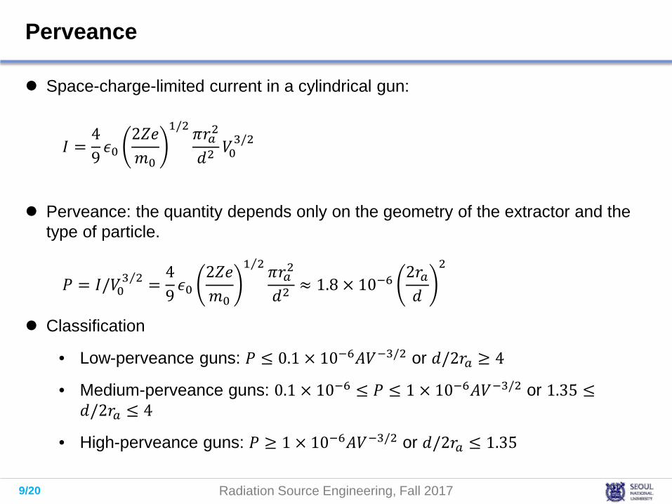
Perveance
Space-charge-limited current in a cylindrical gun:
Perveance: the quantity depends only on the geometry of the extractor and the type of particle.
Classification
• Low-perveance guns: 𝑃𝑃 ≤ 0.1 × 10⁻⁶𝐴𝐴𝑉𝑉−3/2 or 𝑑𝑑/2𝑟𝑟𝑎𝑎 ≥ 4
• Medium-perveance guns: 0.1 × 10⁻⁶ ≤ 𝑃𝑃 ≤ 1 × 10⁻⁶𝐴𝐴𝑉𝑉−3/2 or 1.35 ≤𝑑𝑑/2𝑟𝑟𝑎𝑎 ≤ 4
• High-perveance guns: 𝑃𝑃 ≥ 1 × 10⁻⁶𝐴𝐴𝑉𝑉−3/2 or 𝑑𝑑/2𝑟𝑟𝑎𝑎 ≤ 1.35
𝐼𝐼 =49 𝜖𝜖0
2𝑍𝑍𝑒𝑒𝑚𝑚0
1/2 𝜋𝜋𝑟𝑟𝑎𝑎2
𝑑𝑑2 𝑉𝑉03/2
𝑃𝑃 = 𝐼𝐼/𝑉𝑉0⁄3 2 =
49 𝜖𝜖0
2𝑍𝑍𝑒𝑒𝑚𝑚0
⁄1 2 𝜋𝜋𝑟𝑟𝑎𝑎2
𝑑𝑑2 ≈ 1.8 × 10−62𝑟𝑟𝑎𝑎𝑑𝑑
2
10/20 Radiation Source Engineering, Fall 2017
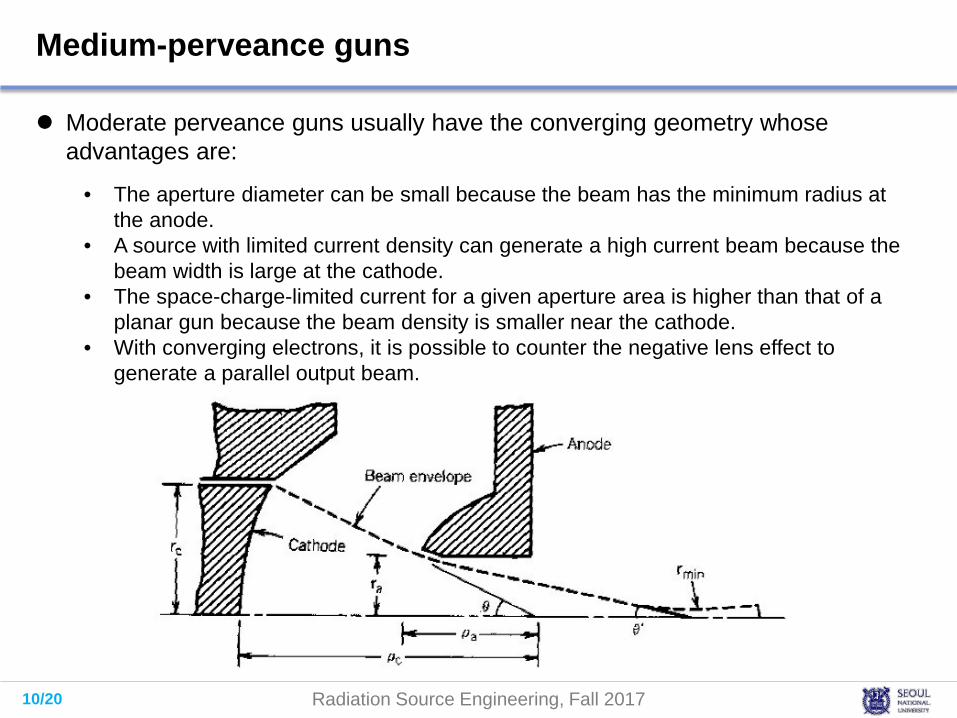
Medium-perveance guns
Moderate perveance guns usually have the converging geometry whose advantages are:
• The aperture diameter can be small because the beam has the minimum radius at the anode.
• A source with limited current density can generate a high current beam because the beam width is large at the cathode.
• The space-charge-limited current for a given aperture area is higher than that of a planar gun because the beam density is smaller near the cathode.
• With converging electrons, it is possible to counter the negative lens effect to generate a parallel output beam.
11/20 Radiation Source Engineering, Fall 2017
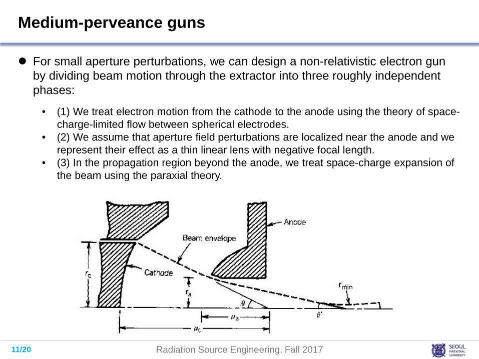
Medium-perveance guns
For small aperture perturbations, we can design a non-relativistic electron gun by dividing beam motion through the extractor into three roughly independent phases:
• (1) We treat electron motion from the cathode to the anode using the theory of space-charge-limited flow between spherical electrodes.
• (2) We assume that aperture field perturbations are localized near the anode and we represent their effect as a thin linear lens with negative focal length.
• (3) In the propagation region beyond the anode, we treat space-charge expansion of the beam using the paraxial theory.

12/20 Radiation Source Engineering, Fall 2017
Medium-perveance guns: (1) converging electron flow between spherical electrodes [Remind] The perveance of a full spherical electron beam:
For the focusing electrode below, the perveance is
𝐼𝐼𝑠𝑠𝑠𝑠𝑠𝑠𝑠𝑟𝑟𝑠𝑠𝑉𝑉𝑎𝑎3/2 =
49𝜖𝜖0
2𝑒𝑒𝑚𝑚0
1/2 4𝜋𝜋[𝛼𝛼( ⁄𝜌𝜌𝑎𝑎 𝜌𝜌𝑐𝑐)]2
𝐼𝐼𝑠𝑠𝑠𝑠𝑠𝑠𝑠𝑟𝑟𝑠𝑠𝑉𝑉𝑎𝑎3/2 =
16𝜋𝜋𝜖𝜖09
2𝑒𝑒𝑚𝑚0
1/2 sin2(𝜃𝜃/2)[𝛼𝛼( ⁄𝜌𝜌𝑎𝑎 𝜌𝜌𝑐𝑐)]2 ≈ 29.4
sin2(𝜃𝜃/2)[𝛼𝛼( ⁄𝜌𝜌𝑎𝑎 𝜌𝜌𝑐𝑐)]2
𝐴𝐴𝑐𝑐 = �0
𝜃𝜃2𝜋𝜋𝜌𝜌𝑐𝑐 sin𝜃𝜃 𝜌𝜌𝑐𝑐𝑑𝑑𝜃𝜃
x4𝜋𝜋𝜌𝜌𝑐𝑐2 sin2(𝜃𝜃/2)
4𝜋𝜋𝜌𝜌𝑐𝑐2
μperv

13/20 Radiation Source Engineering, Fall 2017
Medium-perveance guns: (2) defocus of electrons by radial fields near the anode aperture The focal length for the negative lens action of the aperture is roughly:
To estimate the effect, we set 𝐸𝐸𝑎𝑎 equal to the value of electric field without the beam and aperture
Passing through the aperture, the beam envelope convergence angle changes from 𝜃𝜃 to 𝜃𝜃′
𝑓𝑓 = −4𝑉𝑉0/𝐸𝐸𝑎𝑎
𝐸𝐸𝑎𝑎 ≈ 𝑉𝑉0( ⁄𝜌𝜌𝑐𝑐 𝜌𝜌𝑎𝑎)/(𝜌𝜌𝑐𝑐 − 𝜌𝜌𝑎𝑎)
𝜃𝜃′ = 𝜃𝜃 −𝑟𝑟𝑎𝑎𝑓𝑓 ≈ 𝜃𝜃 1 −
𝜌𝜌𝑐𝑐4(𝜌𝜌𝑐𝑐 − 𝜌𝜌𝑎𝑎)
𝑓𝑓 ≈ −4 ( ⁄𝜌𝜌𝑎𝑎 𝜌𝜌𝑐𝑐)(𝜌𝜌𝑐𝑐 − 𝜌𝜌𝑎𝑎)

14/20 Radiation Source Engineering, Fall 2017
Medium-perveance guns: (3) The minimum radius of the beam emerging from the aperture of a converging gun The beam emerging from the aperture of a converging gun usually has strong
space-charge forces and low emittance.
We can find the axial location where the beam reaches a neck using the beam current (𝐼𝐼), kinetic energy (𝑒𝑒𝑉𝑉0), initial radius (𝑟𝑟𝑎𝑎) and envelope angle (−𝜃𝜃′).
The minimum beam radius in terms of the envelope angle and beam perveanceat the anode is given by:
𝑟𝑟𝑚𝑚𝑚𝑚𝑚𝑚𝑟𝑟𝑎𝑎
= exp−3.3 × 10⁻⁵ 𝜃𝜃′2
𝐼𝐼/𝑉𝑉03/2
𝑑𝑑𝑑𝑑𝑑𝑑𝑧𝑧
= 2𝐾𝐾 ln( ⁄𝑑𝑑 𝑧𝑧 𝑑𝑑𝑚𝑚)
𝐾𝐾 ≡𝑒𝑒𝐼𝐼0
2𝜋𝜋𝜖𝜖0𝑚𝑚0 𝛽𝛽𝛽𝛽𝑐𝑐 3

15/20 Radiation Source Engineering, Fall 2017
Medium-perveance guns: Example
Numerical calculations of converging gun properties using the EGUN code.
Figures show electrodes, computational rays, and electrostatic equipotential lines. Left-hand-side: spherical-section cathode and focusing electrode. Right-hand-side: shaped anode and output tube. V0 = 20 kV, I0 = 1 A. Calculation extends 0.05 m in radius and 0.08 m along the z axis. (a) Initial run — most of the available current strikes the anode. (b) With a corrected focusing electrode, the full current enters the output tube.
37.5°22.5°
16/20 Radiation Source Engineering, Fall 2017
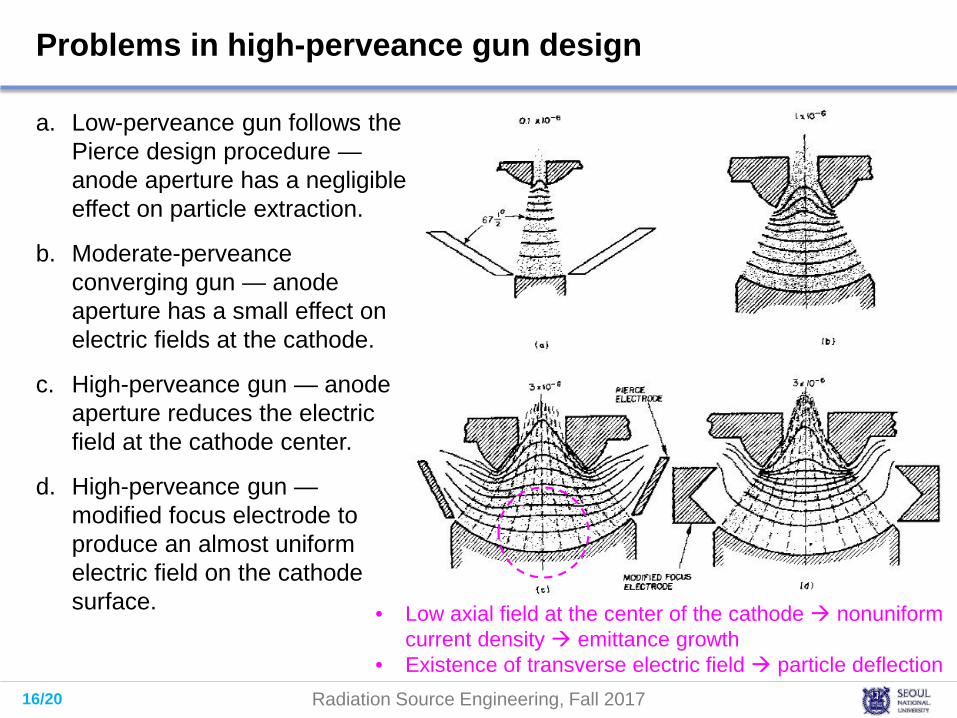
Problems in high-perveance gun design
a. Low-perveance gun follows the Pierce design procedure —anode aperture has a negligible effect on particle extraction.
b. Moderate-perveanceconverging gun — anode aperture has a small effect on electric fields at the cathode.
c. High-perveance gun — anode aperture reduces the electric field at the cathode center.
d. High-perveance gun —modified focus electrode to produce an almost uniform electric field on the cathode surface. • Low axial field at the center of the cathode nonuniform
current density emittance growth• Existence of transverse electric field particle deflection
17/20 Radiation Source Engineering, Fall 2017
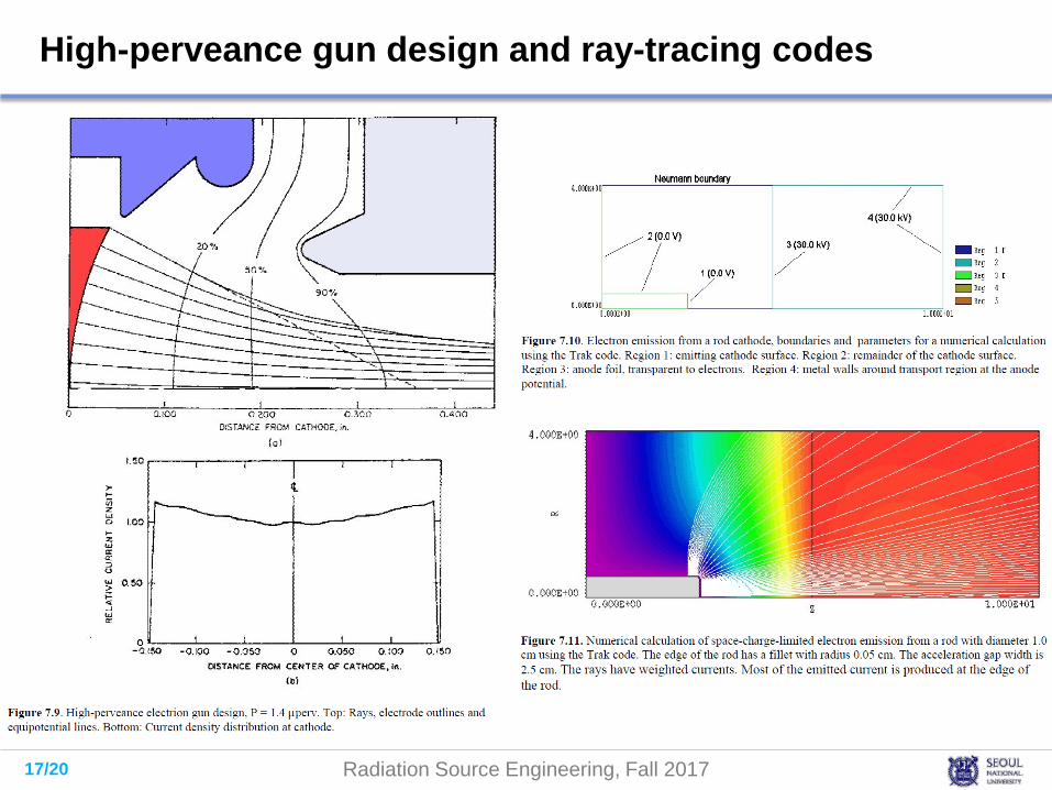
High-perveance gun design and ray-tracing codes

18/20 Radiation Source Engineering, Fall 2017
High-current electron sources: thermionic sources
High-current cathodes are important for microwave tubes, pulsed RF linacs, and induction linac injectors. Recently, there has been considerable interest in sources for high brightness beams that can drive free electron lasers.
High-current electron sources either have a large area or produce a high electron flux. Here, we concentrate on sources that can supply high-current density (> 105 A/m2).
Thermionic sources emit electrons according to Richardson-Dushman law:
Schottky effect (field enhanced thermionic emission): For a constant temperature, the current still slowly increases with the applied extraction potential by lowering the surface barrier:
𝑗𝑗𝑠𝑠 = 𝐴𝐴𝑇𝑇2 exp −11600𝜙𝜙𝑤𝑤
𝑇𝑇
𝑗𝑗𝑠𝑠 = 𝐴𝐴𝑇𝑇2 exp139𝐸𝐸𝑠𝑠
1/2
𝑇𝑇 −11600𝜙𝜙𝑤𝑤
𝑇𝑇
𝐸𝐸𝑠𝑠 : Electric field normal to the surface [kV/cm]
19/20 Radiation Source Engineering, Fall 2017
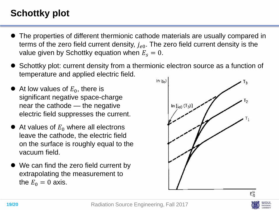
Schottky plot
The properties of different thermionic cathode materials are usually compared in terms of the zero field current density, 𝑗𝑗𝑠𝑠0. The zero field current density is the value given by Schottky equation when 𝐸𝐸𝑠𝑠 = 0.
Schottky plot: current density from a thermionic electron source as a function of temperature and applied electric field.
At low values of 𝐸𝐸0, there is significant negative space-charge near the cathode — the negative electric field suppresses the current.
At values of 𝐸𝐸0 where all electrons leave the cathode, the electric field on the surface is roughly equal to the vacuum field.
We can find the zero field current by extrapolating the measurement to the 𝐸𝐸0 = 0 axis.

20/20 Radiation Source Engineering, Fall 2017
Cathode materials
Commercial thermionic cathodes consist of a high temperature metal substrate (W) coated with a material with low work function (Ba). Unfortunately, barium evaporates rapidly at high temperature.
Dispenser cathodes are fabricated by impregnating porous tungsten with chemical compounds that generate barium when heated. Available dispenser cathodes generate current density in the range 20×104 A/m2 at a maximum operating temperature of 1100°C. To avoid cathode poisoning, dispenser cathodes require a clean vacuum less than 5×10⁻⁷ torr.
Lanthanum hexaboride, LaB6, is an alternative to dispenser cathodes — it has some advantages for pulsed-beam accelerators. The homogeneous material has adequate mechanical strength and an inherently low work function. The material is resistant to poisoning, maintaining its emission properties at pressures in the 10-5 torr range. Also, there is less problem with evaporation of the active material.