Embed Size (px)
Citation preview

Electron-Beam Curing of Thermoset
Resins for Composites
Thierry GLAUSER1999
Akademisk avhandling
som med tillstånd av Kungliga Tekniska Högskolan framlägges till offentlig granskning för
avläggande av teknisk doktorsexamen fredagen den 24 september 1999, kl 10.00 i
kollegiesalen, administrationsbyggnaden, Valhallavägen 79, Kungliga Tekniska Högskolan,Stockholm. Avhandlingen försvaras på engelska.
ISBN: 91-7170-443-4


A mes parents
Pour m’avoir ouvert tant
De fenêtres sur le monde


v
Abstract
Electron-beams (EB) are an alternative to traditional thermal curing when manufacturingthick thermoset composites. It is a quick and energetically efficient technique when curinglarge fiber reinforced parts. Most of the published work on EB-curing deals with curing ofthin layers of resin or with crosslinking of polymers.In this thesis, the curing of acrylic resins is studied to highlight the critical parameters andthe particularities of EB-curing. Tg of the thermoset increases with increasing irradiationdose and levels-off at Tg∞, when the resin is fully cured. As in thermal curing, thetemperature during cure strongly affects the crosslinking of the resin and the thermo-mechanical properties of the cured thermoset. Up to Tg∞, a linear relationship between themaximum temperature during cure and Tg was found.Carbon and glass fiber composites were EB-cured and tested. Adding fibers to the acrylicresins lowered the exotherm, which clearly confirmed the importance of temperature duringcure to fully crosslink the polymer matrix.Comparing EB-, UV- and thermal cure showed that the curing method was not the factorthat most influenced the properties of the cured thermoset. The curing technique imposesconstraints, such as starting temperature and curing time, but it does not influence directlythe polymerization and the network formation. These properties are inherent to themonomer used.An acrylate resin was blended it with a series of alkyl and methacrylate functionalizedhyperbranched polyester. The phase-separated thermoset exhibited increased toughness.
Keywords: electron-beam, thermoset, acrylic resin, hyperbranched polyester, thermaleffect, toughening


vii
List of Articles
This thesis is a summary of the following articles:
1 - “Electron-Beam Curing of Thermoset Composite Matrices” T. Glauser, M. Johansson, A. Hult Polymer, 1999, 40, 5297
2 - “Electron-Beam Curing of Thick Thermoset Composites: Effect of Temperature andFiber”
T. Glauser, M. Johansson, A. HultMacromol. Mater. Eng., Accepted for publication
3 - “A Comparison of Radiation and Thermal Curing of Thick Composites”T. Glauser, M. Johansson, A. HultMacromol. Mater. Eng., Accepted for publication
4 - “Toughening of Electron-Beam Cured Thermoset Resins”T. Glauser, M. Johansson, A. Hult, X. Kornmann, L. BerglundManuscript.
It also contains parts of the following article:
5 - “Radiation Curing of Hyperbranched Polyester Resins”M. Johansson, T. Glauser, G. Rospo, A. HultJ. Appl. Polym. Sci., Accepted for publication.


9

ix
Table of Contents
1 - Introduction 1
2 - Background 52.1 Electron-Beam..................................................................................................... 5
2.1.1 Ionizing radiation 62.1.2 Electron-Beams 62.1.3 Electron-Material Interaction 72.1.4 Dosimetry 9
2.2 Thermoset Polymers .......................................................................................... 92.2.1 Monomer structure 112.2.2 Curing of Thermosets 112.2.3 Thermal and Radiation Curing 13
2.3 Acrylic Resins ....................................................................................................132.3.1 EB-Curing of Acrylic Resins 14
2.4 Dendritic Polymers............................................................................................152.5 Composites........................................................................................................16
2.5.1 Fiber Reinforcement 162.5.2 Polymer Matrix 172.5.3 Curing 172.5.4 Trends in Composites 18
2.6 Experimental......................................................................................................182.6.1 Instrumentation 192.6.2 Materials 192.6.3 Synthesis of toughening additives 202.6.4 Sample Preparation 232.6.5 Chemical Characterization 242.6.6 Physical and Mechanical Testing 25
3 - Important EB-Parameters 293.1 Initiation & Cure of Acrylic Thermoset Resins ..............................................293.2 Temperature Evolution.....................................................................................29
3.2.1 Resin Reactivity 293.2.2 Sample Geometry and Effect of Mold 301.1.3 Effect of Dose and Dose Rate 31
3.3 Network Formation ...........................................................................................323.4 Vitrification..........................................................................................................34
4 - Effect of Fibers on Matrix 374.1 Effect of the Fiber on Tmax ...............................................................................374.2 Relation between Tg and Tmax.........................................................................39

EB-Curing of Thermoset Resins for Composites
x
4.3 Network Homogeneity......................................................................................404.4 External Heating................................................................................................42
5 - Radiation vs. Thermal Curing 455.1 Optimization of Cure Systems ........................................................................455.2 Cure of Resin.....................................................................................................465.3 Comparison of Cured Samples ......................................................................485.4 Comparison of Composites.............................................................................50
6 - Matrix Toughening 536.1 Synthesis and Blending ...................................................................................536.2 Phase separation..............................................................................................546.3 Cured additive ...................................................................................................556.4 Cured resin.........................................................................................................556.5 Toughness .........................................................................................................57
7 - Conclusions 59
Acknowledgments 63
References 65

1
1 - Introduction
Composites are growing in importance and are moving from high-tech applications toconsumer goods. Therefore the importance of price and production time increases. Forcuring thick composites, electron beam (EB) is an alternative to today’s standard, thermalcuring. In order to master EB-curing it is important to have a good understanding of notonly traditional polymer sciences, such as polymerization chemistry and mechanicaltesting, but also of radiation physics and chemistry. Much work has been carried out inthese different fields but there is only little work published on the combination of thesefields. For EB to gain some industrial importance, it is important to link the availableknowledge and to have basic understanding of the different processes taking place whencuring thick, fiber reinforced composites.The main goal of this thesis is to increase the understanding of EB-curing by identifying thecritical parameters for curing acrylic resins, and how parameters, such as fibers andtemperature, influence the final properties of composites. In the same viewpoint, EB-curingwas compared to thermal and UV-curing, which have been more thoroughly investigated,in order to identify the major differences and similarities between these techniques. Ageneral problem for composites is their brittleness, therefore toughening systems have beendeveloped for conventional thermally cured applications. To our knowledge, no tougheningsystem has been developed or adapted to EB-curing systems. Hence a toughening systemwas developed based on the knowledge acquired in the first part of this study.

EB-Curing of Thermoset Resins for Composites
2
This study is organized as follows:
− In chapter 2, basic facts and concepts relevant to the work in the followingchapters are presented.
− In chapter 3, EB-curing of acrylic resins is discussed. The effect of the mostimportant cure parameters on the final properties of the material is highlighted.
− In chapter 4, results from the previous chapter are used to investigate the effect offibrous reinforcement on the polymeric matrix.
− In chapter 5, EB-, UV- and thermal curing are compared. The influence of thedifferent processes on the properties of the cured material is discussed.
− In chapter 6, the principles of a toughening system based on hyperbranchedadditives are presented.

3


5
2 - Background
This chapter is intended to give some background information to the reader about thedifferent fields this thesis deals with. The first section concerns electron-beams as energysources and their interaction with matter, more specifically polymers.The second section is a short presentation of different kinds of monomers and polymers.The third section is directly linked to the second one and presents the main concepts ofpolymerization. Radiation curing of acrylic resins is more specifically treated.In the fourth section is presented the family of dendritric macromolecules, which includesdendrimers and hyperbranched polymers.The curing of large, thick composites is described in the fifth section, as well as thedifferent parts constituting composites, namely reinforcement fibers and polymer matrices.Finally different methods used to characterize materials chemically, physically andmechanically are described.
2.1 Electron-BeamWith the development of nuclear science at the end of World War II, radiation chemistrybecame a new and hot field of research. It is not surprising that there was much interest inirradiating a class of materials that had gained an industrial importance during the war:polymers. After a peak in the 60’s,1,2,3 interest for radiation chemistry on polymersdecreased as people became aware of the danger of radioactivity. With today’s technology,ionizing radiation can be produced without any radioactive compound being involved orproduced, why they can be used to cure rapidly thick composites with improved properties
2.1.1 Ionizing radiationHigh energy, or ionizing, radiation includes electromagnetic (X- and γ-rays) andcorpuscular radiation (α-particles, electrons) with a particle energy in the range 103-106 eV.4 The most commonly used units in radiation chemistry are:
− The dose expressed in Grays (Gy) defined as 1 J of energy of ionizing radiationtransferred to 1 kg of substance. Thus, under the same irradiation, differentmaterials will be subjected to different doses depending upon their density.
− The dose rate (Gy/s) corresponds to the dose absorbed per second.− Electron volts (eV) are used to give the energy of particles and accelerators.− The G-value is the energy yield. It can be defined as the number of molecules
undergoing a certain process per 100 eV of absorbed energy. Typically a chainprocess such as polymerization will have a G-value in the range 102-108. The

EB-Curing of Thermoset Resins for Composites
6
transformation of a macromolecule, such as chain scission and degradation, has G-value between 1 and 100.
2.1.2 Electron-BeamsDifferent types of ionizing radiation sources are available. They can be divided into theelectron accelerator type and the nuclear type, where a radioactive isotope produces γ-rays.5
Accelerators are convenient, since they are not radioactive and have a continuous energeticspectrum.The linear accelerator (linac), depicted in Figure 2-1(B), is the most common electronaccelerator for industrial applications where a penetration depth in the centimeter range isneeded. Electrons produced by a cathode are accelerated in vacuum by an electric fieldcreated by a series of aligned cathodes with an increasing potential. The negatively chargedelectrons travelling through this field reach high speed, or energies. The beam is thenfocused by a series of magnetic fields, and finally hits its target after passing through acooled metallic window. The out-coming electron beam can be a "spot", or a sweepingbeam if submitted to an oscillating magnetic field.In the present study a microtron, shown in Figure 2-1(A) was used. It works on the sameprinciple as the linac, but in the accelerator the electrons have a circular trajectoryperpendicular to an applied magnetic field. The electrons follow increasing circular pathsafter each passage through a strong electric field, which boosts up their energy. Thistechnology is somewhat more complicated. It is therefore not as widespread as the linac,but the resulting beam is identical.Different types of EBs are used for different applications. The important parameters oftenbeing the penetration depth of the electrons and the dose rate delivered by the EB. 6
Typically the coating industry, which cures thin films at a high speed, use a different kindof accelerator, called curtain accelerator, producing low penetrating electrons at high doses.Other fields of application for EBs are sterilization of medical equipment, crosslinking ofheat-shrinkable polyethylene films, or functionalization of polymer surfaces by grafting.

2 -Background
7
Beam al ignment and s canning
Cathode
W indow
BE
Figure 2-1: A microtron (A) was used in this study. Linacs (B) are the most commonly usedelectron sources due to their relative simplicity. The radiation produced by these two sources issimilar.
2.1.3 Electron-Material InteractionWhen impacting matter, strongly accelerated electrons (primary electrons) lose energy by aseries of inelastic chocks with orbital electrons. This interaction produces secondaryelectrons may either be ejected from their parent atom (ionization, [1]), or be moved to anorbit of higher energy (excitation, [2]). This is called the primary radiation-chemicalprocess. The ionized atom or molecule is in an unstable state, and may undergodecomposition [3] or react with a neighboring molecule. If a cation traps an electron [4], oran anion looses an electron, it will give a molecule in an excited state. The ejected electronmay recombine with its parent atom to give a highly excited atom [4], or it may be capturedelsewhere, giving a negative ion [5]. This energy transfer can produce physical and/orchemical changes.
ABh ν → AB[ ]+ + e − [1]
ABh ν → AB[ ]* [2]
AB[ ]+ → A+ + B [3]
AB[ ]+ + e− → AB[ ]* [4]
AB + e− → AB[ ]−
[5]
As can be seen in equations 1 to 5, a whole range of products is obtained during irradiation.[AB]* are in an excited electronic state, but not ionized. The excited molecules undergo asecondary radiation-chemical process, in which the initial energy is redistributed and thestructure of the final radiation products defined. If the energy is sufficient and localized in abond, the molecule decomposes giving two radicals, i.e. species with an unpaired electron[6].

EB-Curing of Thermoset Resins for Composites
8
AB[ ]* → A • + B • [6]
The resulting radicals can undergo recombination [7], disproportionation [8] or substitution(chain transfer) [9].
A• + B• γ M [7]A• + B• γ M1 + M2 [8]A• + MH γ AH + M• [9]
There is a great variety of excited molecules, ions, and radicals coexisting duringirradiation. These species may then react with molecules that are not directly affected byradiation.At very high energies an appreciable amount of energy is lost by the production of X-ray.At the same time, the risk for induced radioactivity is strongly increased. These two factorsgive a practical limit of 10 MeV for EBs, since the energy conversion drops andsupplementary radiation protection is required.The penetration depth of the electrons in the matter depends on their energy, and thedensity of the material, i.e. denser materials stop electrons faster. The maximum dose is notreached at the surface of the material, but at some depth due to back-scattering by the atomnuclei, as can be seen in Figure 2-1. Usually the penetration depth is defined as 90% of theinitial dose, or dose at the surface. To increase the penetration depth, the sample can beirradiated from both sides. The thickness curable by a double-sided irradiation is more thantwofold that which can be achieved by a single sided since there is an accumulation of doseat the center of the piece.
100 %
90 %
D / 3 0 DThi c kne ss
DoseDoubl e irrad iation
Frontirradiation Back
irradiation
Figure 2-1: The increased dose under the surface is due to back-scattering of the primaryelectrons by the atom nuclei. The dose at the surface is defined as 100%. Double-sidedirradiation is the sum of the front side and the back side irradiation. Therefore if 90% of thesurface dose is needed to complete cure, a double sided irradiation allows to cure more thandouble the thickness cured with a single sided irradiation (factor 3 in this case).

2 -Background
9
Irradiation induces direct thermal effects in the sample, since the absorbed energy finallydegenerates into thermal energy. Radiation induced chemical reactions can also havethermal effects. For example, polymerization of monomers is exothermic, and often givesthe strongest contribution to the heating of the sample.
2.1.4 DosimetryIt is important to know the dose delivered by the EB, as well as the dose received byirradiated samples. There are numerous different methods available, which are more or lessadapted to the different applications and energy ranges.5 In this study, calorimetry was usedto calibrate the EB. The temperature increase of a known amount of water in an isolatedcontainer was measured after irradiation. This thermal energy was then converted, using acalibration table, into the dose delivered to the sample.The dose received by the samples was measured by a chemical method. The change inabsorption (280 cm-1) of a film of cellulose triacetate (CTA), which was placed on thesample during cure, was recorded by UV-spectroscopy. 7 A calibration curve was used toconvert the “yellowing” of the film into the dose received.
2.2 Thermoset PolymersPolymers can generally be divided into two main families: thermosets and thermoplastics.Thermoplastics are linear or branched macromolecules that can have side-chains or pendinggroups, as seen in Figure 2-1(A). These polymers can be molten for reuse or recycling.On the other hand thermosets, Figure 2-1(B), are crosslinked and have a three-dimensionalnetwork structure.8 It can be considered as a single molecule. Therefore, once cured,thermosets can not be molten, and they are not prone to a slow flow leading to deformation,as thermoplastics are.The first synthetic industrial thermoset, Bakelite™, was patented at the beginning of thecentury. 9 Nowadays, thermosets are used in a wide range of applications. The largest, interms of quantity, are probably surface coatings. An example of surface coating is paint,which can be seen as a barrier that protects the underlying substrate, and/or as an estheticfinish that gives a certain color and gloss. Two other major application areas for thermosetsare adhesives/glues, and encapsulation of electronic components to provide protection. Allthe above mentioned applications deal with thin layers of resin. In composites, thethermoset can be seen as a binder for the load-bearing fibers. In such applications, veryrigid materials with a high modulus are needed. Highly crosslinked networks usuallyachieve the required stiffness. In thick parts it is difficult to evacuate the thermal energyfrom the exothermic reaction. Therefore, elaborate curing schemes are adapted to tame thereaction so that thermal degradation is avoided.

EB-Curing of Thermoset Resins for Composites
10
• •
•
•
••
••
•
•
•
•
•
R•
R•
A
B
Figure 2-1: A monomer with a single vinyl group (functionality of 2) will give a thermoplastic(A). It is composed of large, independent macromolecules. With two vinyl groups (functionalityof 4) all molecules are linked to one another to form one single macromolecule (B).
2.2.1 Monomer structureThe monomer is a molecule, with a functionality of at least 2, that is used as a buildingblock for polymers. It is defined by its size, chemical composition and the number and typeof functional groups.10
The size, or molecular weight, and the chemical composition of the monomer influence thematerial’s properties before and after cure. A non-polar monomer with a low molecularweight has a low viscosity. Once cured, it is likely to yield a densely crosslinked, hencebrittle, material. A more polar monomer often gives a polymer with superior ultimateproperties. It should be kept in mind that processing often requires a viscosity within agiven range. For example, a low viscosity is needed for injection molding, whereas resinsused for prepregs must nearly solid at room temperature.The number of functional groups determines the type of structure the polymer will have. Afunctionality of two will produce a thermoplastic (c.f. Figure 2-1 (A)). When thefunctionality is increased, a thermoset is obtained (c.f. Figure 2-1 (B)). With increasingfunctionality, the crosslinked material will have a higher crosslink density, stiffness andfragility.The type of functional group not only determines the route (chain- or step-wise) by whichthe monomers will cure, but also the technique by which curing can be performed. Forexample, acrylic resins (acrylates, methacrylates) can be directly cured by EB whereasepoxies require the addition of a catalyst.
2.2.2 Curing of Thermosets
Step-Wise and Chain-Wise PolymerizationCrosslinking or polymerization can basically be done by two mechanisms: step-wise orchain-wise.

2 -Background
11
The step-wise mechanism is a gradual process where the structure is built up in stepsthroughout the system. Upon initiation, two monomers react together to form a dimer. Thedimer will further react with another monomer or dimer, forming a trimer or a tetramer, andso on, as is described in Figure 2-1(A). Eventually a macromolecule has been formed. Themolecular weight of the thermoplastic, or the crosslink density of the thermoset, graduallyincreases in the system.
A
A
B
BA
AA
AA
A
B BB
B
BB
A
A A
AA
A A
A
BB
B
BB
B
B
B
A
B
R• R
•
R
•
A
B
Figure 2-1: In a step-wise polymerization (A) molecular weight increases slowly andprogressively. In a chain-wise polymerization (B) monomers add to the reactive end of livingchain. A mixture of monomers and macromolecules is rapidly obtained.
During the chain-wise mechanism, an active species is formed at first. This species willthen initiate a chain polymerization reaction, as can be seen in Figure 2-1(B). A moleculewith high molecular weight will rapidly be produced by addition of monomers at thereactive chain end. Finally, the reactive center is destroyed by termination (c.f. Equations[7]-[9]).
Gelation and VitrificationGelation and vitrification are the two main transitions that can occur during cure.Gelation corresponds to the formation of an infinite molecular network. It gives rise to longrange elastic behavior in the macroscopic fluid. After gelation, a sol (solvent soluble) and agel (non-solvent soluble) co-exist. As the reaction proceeds, the fraction of gel increases tothe detriment of the sol fraction. Usually gelation does not influence the propagation rate.Vitrification occurs when Tg rises to the cure temperature (Tcure). The material is glassywhen Tcure<Tg, whereas it is liquid or rubbery when Tcure>Tg. This transformation isindependent from gelation. In the vitrified state, the rate of cure is drastically decreased,since the reaction is diffusion controlled instead of kinetic controlled. However it ispossible to continue curing by heating the partly cured material above its Tg. During cureabove the ultimate glass transition temperature (Tg∞) of the polymer, only gelation willoccur. When curing at a lower temperature, the polymer will go through gelation and thenvitrification. In thermal curing of thermosets, the cure temperature influences the structureof the network and the residual stresses.11
EB-Curing of Thermoset Resins for Composites
12
Time-Temperature-Transformation (TTT) diagrams are helpful tools for predicting andunderstanding these phenomena.12
Chain-wise polymerization quickly yields an inhomogeneous mixture of monomers andmacromolecules, therefore a gel is formed rapidly. A four-functional monomer willtypically gel around 5% of conversion, whereas the step-wise reacting epoxy-amine systemwill gel when the conversion of reactive groups is around 50-60%.
2.2.3 Thermal and Radiation CuringEnergy is often needed to create reactive species and start a chain polymerization. The mostcommonly used source is heat. A thermally activated initiator produces a reactive speciesthat adds to a monomer by opening a double bond to form a new reactive center. Thisprocess is repeated as new monomers are added to the growing chain and propagate thereactive center. The destruction of this center terminates the growth of the polymer.Peroxides are often used as initiators for thermal curing, since the oxygen-oxygen bond iseasily broken, creating two radicals.Curing by ultra-violet (UV) light and EB are often grouped under the denomination ofradiation curing. An initiator is needed for UV curing in order to start the reaction. 13,14 Itcan be seen as a target molecule, which absorbs the incoming photons and breaks up intoone or more reactive species.The ionizing radiation of EB non-selectively breaks bonds throughout the monomer andpolymer mixture, thereby creating reactive centers all over without adding an initiator.Most of these reactive centers can initiate the chain polymerization of the double bonds.Degradation occurs as bonds of the polymer chain can also be broken, thereby loweringmolecular weight or crosslink density. Degradation and crosslinking (or polymerization)usually take place simultaneously.15
2.3 Acrylic ResinsAcrylic resins, i.e. acrylates and methacrylates, are part of the vinyl family since they havea terminal double bond. Comparing the polymerization of methylacrylate withmethylmethacrylate monomers, both the heat of polymerization and the propagation rateare substantially larger for the former.16 This means that the acrylate functional resin mayproduce more heat and polymerize more rapidly than the methacrylate. Polymethacrylatesgenerally exhibit a higher Tg compared to polyacrylates due to a stiffer main chain.17 Thiswill be of importance if the polymerization proceeds into the vitrified state.
2.3.1 EB-Curing of Acrylic ResinsThe reactive species discussed in the preceding paragraphs (2.2 and 2.3) can be anions,cations or radicals. This study only deals with radicals, therefore the two other types willnot be discussed.A radical is a molecule with an unpaired electron. 18 It can have a lifetime of a few fractionsof a second or be persistent, depending on how much it is stabilized by its electronicenvironment.19 Free radicals are generally very reactive why free radical polymerization isnon-selective and many side reactions occur. It is usually not as well defined as ionicpolymerization.
2 -Background
13
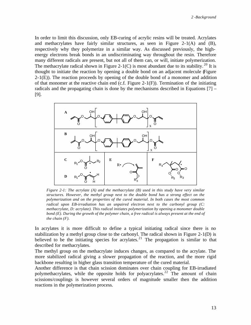
In order to limit this discussion, only EB-curing of acrylic resins will be treated. Acrylatesand methacrylates have fairly similar structures, as seen in Figure 2-1(A) and (B),respectively why they polymerize in a similar way. As discussed previously, the high-energy electrons break bonds in an undiscriminating way throughout the resin. Thereforemany different radicals are present, but not all of them can, or will, initiate polymerization.The methacrylate radical shown in Figure 2-1(C) is most abundant due to its stability. 20 It isthought to initiate the reaction by opening a double bond on an adjacent molecule (Figure2-1(E)). The reaction proceeds by opening of the double bond of a monomer and additionof that monomer at the reactive chain end (c.f. Figure 2-1(F)). Termination of the initiatingradicals and the propagating chain is done by the mechanisms described in Equations [7] –[9].
R1O R2
O•
OR3
O
R•
O OOOOH
OO
OH
x
O OOOOH
OO
OH
x
A
B
C
D
E F
•R1
O
O H
H
•
OR3
OO
R3
OR4
Figure 2-1: The acrylate (A) and the methacrylate (B) used in this study have very similarstructures. However, the methyl group next to the double bond has a strong effect on thepolymerization and on the properties of the cured material. In both cases the most commonradical upon EB-irradiation has an unpaired electron next to the carbonyl group (C:methacrylate, D: acrylate). This radical initiates polymerization by opening a monomer doublebond (E). During the growth of the polymer chain, a free radical is always present at the end ofthe chain (F).
In acrylates it is more difficult to define a typical initiating radical since there is nostabilization by a methyl group close to the carbonyl. The radical shown in Figure 2-1(D) isbelieved to be the initiating species for acrylates.21 The propagation is similar to thatdescribed for methacrylates.The methyl group on the methacrylate induces changes, as compared to the acrylate. Themore stabilized radical giving a slower propagation of the reaction, and the more rigidbackbone resulting in higher glass transition temperature of the cured material.Another difference is that chain scission dominates over chain coupling for EB-irradiatedpolymethacrylates, while the opposite holds for polyacrylates.22 The amount of chainscissions/couplings is however several orders of magnitude smaller then the additionreactions in the polymerization process.
EB-Curing of Thermoset Resins for Composites
14
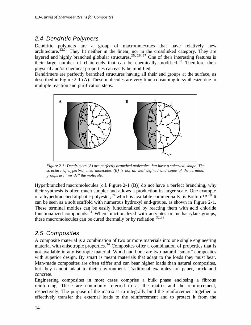
2.4 Dendritic PolymersDendritic polymers are a group of macromolecules that have relatively newarchitecture.23,24 They fit neither in the linear, nor in the crosslinked category. They arelayered and highly branched globular structures.25, 26, 27 One of their interesting features istheir large number of chain-ends that can be chemically modified.28 Therefore theirphysical and/or chemical properties can easily be modified.Dendrimers are perfectly branched structures having all their end groups at the surface, asdescribed in Figure 2-1 (A). These molecules are very time consuming to synthesize due tomultiple reaction and purification steps.
A B
Figure 2-1: Dendrimers (A) are perfectly branched molecules that have a spherical shape. Thestructure of hyperbranched molecules (B) is not as well defined and some of the terminalgroups are “inside” the molecule.
Hyperbranched macromolecules (c.f. Figure 2-1 (B)) do not have a perfect branching, whytheir synthesis is often much simpler and allows a production in larger scale. One exampleof a hyperbranched aliphatic polyester,29 which is available commercially, is Boltorn™.30 Itcan be seen as a soft scaffold with numerous hydroxyl end-groups, as shown in Figure 2-1.These terminal moities can be easily functionalized by reacting them with acid chloridefunctionalized compounds.31 When functionalized with acrylates or methacrylate groups,these macromolecules can be cured thermally or by radiation. 32,33
2.5 CompositesA composite material is a combination of two or more materials into one single engineeringmaterial with anisotropic properties.34 Composites offer a combination of properties that isnot available in any isotropic material. Wood and bone are two natural “smart” compositeswith superior design. By smart is meant materials that adapt to the loads they must bear.Man-made composites are often stiffer and can bear higher loads than natural composites,but they cannot adapt to their environment. Traditional examples are paper, brick andconcrete.Engineering composites in most cases comprise a bulk phase enclosing a fibrousreinforcing. These are commonly referred to as the matrix and the reinforcement,respectively. The purpose of the matrix is to integrally bind the reinforcement together toeffectively transfer the external loads to the reinforcement and to protect it from the

2 -Background
15
surrounding environment. The matrix gives a composite its shape, surface appearance,environmental tolerance and overall durability, but it is the fiber reinforcement that carriesmost of the structural loads, and thereby largely dictates the macroscopic stiffness andstrength of the composite.
2.5.1 Fiber ReinforcementThe most common reinforcement fibers are carbon (C), glass and aramid fibers. They offera wide range of properties, and are moving from high-tech applications to leisure andconsumer goods, as prices slowly decrease.Glass fiber’s main advantages are high strength, very good heat and corrosion resistance,and low price. Carbon fibers have the highest strength and stiffness of all fibers, and arequite insensitive to moisture. Their main drawback is their high price. Aramid fibers, suchas Kevlar™, have very good toughness and damage tolerance, but moderate hightemperature tolerance. Unfortunately they are moisture sensitive and fairly expensive.Fibers are used in different ways depending on the final application. For high performanceparts, continuous fibers or weaves are often used, but manufacturing is often timeconsuming and the complexity of the part limited. For applications where cost is a moreimportant issue short fibers are used. An intermediate solution is prepreg, which is a fabricpre-impregnated with resin. These sheets are cut to the size of the part to be manufactured,then they are stacked (layed-up), compacted and finally cured together.It is usually assumed that the transfer of mechanical forces is ideal, thus that the adhesionbetween the fiber and the matrix is perfect. In fact, the interface is often the weak point,since most of the fibers are inert and have smooth surfaces. To improve the adhesion, thefiber manufacturer often treats the fiber or applies a sizing to it, which improves wettabilityand/or adds chemically reactive groups. The composition of a sizing is often a well-keptindustrial secret.
2.5.2 Polymer MatrixThermosets are the most commonly used resins for high performance composites. Theirlow viscosity prior to cure simplifies manufacturing. Moreover, the highly crosslinkednetwork allows a better transmission of load between the fibers and a higher overallstiffness.Epoxies and unsaturated polyesters are the most widespread thermoset matrices. Epoxiesare used in applications where high strength, stiffness and temperature tolerance arerequired. Thus they are the most common matrix for carbon fibers. Unsaturated polyestersoffer an attractive combination of low price, reasonable mechanical properties and ease ofprocessing, but they normally have poor UV-resistance.Acrylates have not been used much in composites. Since they undergo auto-accelerationduring cure, extremely high temperatures are reached in thermally cured thick pieces,thereby causing thermal degradation of the matrix. However, when EB-curing starttemperature is around room temperature, why the risk of having thermal degradation isconsiderably lowered. Acrylates are used in the same type of applications as epoxies.
2.5.3 CuringFor thermally curing large composites, large ovens are needed. Autoclaves, in whichpressure and temperature are applied simultaneously, are used when a pore-free high

EB-Curing of Thermoset Resins for Composites
16
performance composite is required. This type of equipment is not only expensive, but alsoenergy and time consuming since thermal gradients and thermal degradation must beavoided.UV-light can be used in some applications. Energy consumption is low, and initialinvestment is relatively low. However it is limited to fairly thin layers of transparentcomposites, since the penetration depth of UV-light is limited due to scattering by the resinand the fibers. It can not be used with opaque fibers, such as carbon and aramid fibers. UV-light has been applied to in-situ repairs of large composites.EB-curing has been used since the 70’s for curing large composites.35, 36, 37 Mostapplications are for the air, space or military industry, 38 hence very little has been publishedon this topic. High energy EBs (10 MeV) allow curing of thick composites, up to 4 cm witha double-sided irradiation. Since curing starts at room temperature, much lowertemperatures, compared to thermal curing, are reached in the core of the part, therebydecreasing the risk for thermal degradation. Moreover, there is no need for heating orcooling, so shorter curing cycles are achieved.39 Acrylates have been directly cured by afree-radical mechanism.40 To cure epoxies a cationic catalyst must be added.41,42
2.5.4 Trends in CompositesOne of the main issues in composites is price, i.e. initial investment is often high, and highperformance composites require skilled labor. Initial investments are quite similar for alarge autoclave and an EB source. EB requires extra shielding for radiation protection andsupplementary security so workers do not get irradiated. The major advantages of EB are:
− Shorter processing time (up to a factor six)− Better use of energy− Minimized risk for thermal degradation− Lower thermal and mechanical requirements on tooling
The largest drawback for EB is that it is a new technology. Only little data is published andthe knowledge is quite scarce, especially compared to the well-studied thermally curedepoxy system.
2.6 ExperimentalThis section starts with a description of the instruments and materials used in the presentstudy. It is followed by a description of the chemistry used to functionalize hyperbranchedpolyesters used as toughening agents. Then, preparation of test samples is explained.Finally, chemical characterization, as well as physical and thermo-mechanical testing, ofcured samples are discussed.
2.6.1 InstrumentationEB-curing was performed with a pulsed sweeping electron beam, produced by a microtronaccelerator with an energy of 6.5 MeV and a current of 80 mA. The dose could be variedbetween 10 and 30 kGy per sweep by changing the length of the pulse. The dose calibration

2 -Background
17
of the instrument was performed using a Risø calorimeter. The UV equipment was an Oriel8180 equipped with a high pressure Xe-Hg lamp (1 kW, 23.2 mW/min). Thermal curingwas performed in a convection oven. Temperature of the resin during cure was measuredwith a thread thermocouple and recorded by a Combilab equipment from ChipzobitsDigitalteknik AB, Sweden. The temperature of the oven during cure was measured with thesame equipment. The thermo-mechanical properties were measured using a DynamicMechanical Thermal Analyzer (DMTA) Mk II from Polymer Laboratories. The toughnessmeasurements were done on a Minimat miniature mechanical test machine from PolymerLaboratories. The FT-Raman and the FT-IR spectra were recorded on a Spectrum 2000spectrometer from Perkin Elmer. The UV-spectra were recorded with a Diode ArraySpectrophotometer HP 8451A from Hewlett Packard. 1H NMR spectra were recorded on aBruker AM 400 at 400 MHz using CDCl3 as a solvent. The SEC measurements wereperformed at room temperature on a Waters 6000A pump equipped with two PL gel 10 µmmixed-B columns (300x7.5 mm) from Polymer Labs and a refractive index detector.Chloroform was used as mobile phase using a flow rate of 1 ml min-1. Calibration wasperformed with linear polystyrene standards in the molecular weight range 2000-3x10⁶
g/mole.
2.6.2 MaterialsTwo resins from UCB, Belgium, based on a bisphenol-A epoxide were investigated. Onewas acrylate functional (Ebecryl 600, EB 600) whereas the other one had methacrylatereactive groups (Ebecryl 610, EB 610). SEC indicated a low polydispersity and similarvalues for both resins (EB 600: Mn=700 Daltons, Mw=790 Daltons, PDI=1.13; EB 610:Mn=710 Daltons, Mw=780 Daltons, PDI=1.10). No initiator was used for EB-curing inorder to have a free-radical cure. A hyperbranched aliphatic polyester (Boltorn™ H40),described in Figure 2-1, was functionalized and used as an additive. All other chemicalswere purchased from Aldrich or Lancaster and used as received.For UV-curing, a photo-bleaching photoinitiator (Lucerin® LR 8728 from BASF) was usedin order to insure a homogeneous free-radical cure throughout the sample thickness. 1, 3 or5 wt.-% initiator was added to the resin.For thermal curing, dicumyl peroxide was used as a free-radical initiator at concentrationsof 0.5, 2, respectively 4 wt.-%. The half-life of this peroxide is 13 h at 115 °C.10
Sizing-free carbon fiber was used as provided. The sizing of the E-glass fiber was burnt offat 530 °C for 12 h. Both fiber types were cut to an approximate length of 5 mm.

EB-Curing of Thermoset Resins for Composites
18
OO
O OO
O
O
O
O
OOH
O
O
O O
O
O O
O
HO
O
O
OO
O
HO
O
O
HO O
O
O
O
O O
OH
O
O
HO O O
O
O
HO O
O
OHO
OO
O
O
O O
O
OH
O
O
O
O
OHOO
O
O
O
OHO
OO
OHO
O
O
HO
O
OOH
O
O OH
O
O
O
O
O
OH
O O
O
O
O
OH
OOH
O
O
OO
OO
OH
OO
HOO
O
HO
O
O
O
O
O
OH
O
O
O
O
O
OH
O OH
O
OOH
OHO
HOOH
O
OHHO
OO
HO
O
OHO
OHO
HO
O
HOHO
O
OHHO
O OH
OH
O
O O
O
HO OH
O
OH
OH
O OH
OH
O
OH
OH
OHO
HO
O
OH
OH
OOH
OH
OOH
OH
OHO
HO
O
OHHOO
HO
HO
O
HO
HO
Figure 2-1: Boltorn™ is a hydroxy functional hyperbranched aliphatic polyester, whichtheoretically has 64 terminal hydroxyl groups.
2.6.3 Synthesis of toughening additivesA hydroxy-functional hyperbranched aliphatic polyester (Boltorn™, 4G-OH) based on 2,2-bis(hydroxymethyl)propionic acid (bis-MPA) as AB2 monomer and ethoxylated(5EO/penta) pentaerytritol (PP50) as core, was used as base for all resins. The polyester hada bis-MPA:PP50 ratio of 60:1 (theoretically 64 OH-groups/molecule) and was used asreceived. The degree of branching was around 0.45 as determined with 13C NMR.43 Moreextensive descriptions of the synthesis and characterization of the hyperbranched polyesterscan be found elsewhere.44
All additives were synthesized according to the same general procedure. The onlydifference between the different additives, listed in Table 2-1, is the proportion ofmethacrylic anhydride and acid chloride. The synthesis of additive 3, described below, is atypical example.
Table 2-1: Description of the functionalized hyperbranched polyesters used as additives. Thedegree of acrylation and the alkyl chain length vary. The degree of methacrylation wasmeasured by 1H NMR. Hydroxyl groups were fully substituted.
Additive Methacrylate[%]
Alkyl (-ene) moiety
Aimed Measured Type
1 10 9 Octanoate, C82 10 10 Decanoate, C10

2 -Background
19
3 20 23 Octanoate, C84 20 20 Decanoate, C105 20 18 10-undecenoate, C116 40 43 Hexanoate, C67 40 48 Octanoate, C88 40 38 Decanoate, C109 40 37 10-undecenoate, C11
Synthesis of additive 3Boltorn™, 4G-OH, (20.00 g, 2.73 mmol, 174.4 mmol-OH), N,N-dimethylaminopyridine,(DMAP) (0.43 g, 3.55 mmol) and triethylamine (TEA) (10.00 g, 98.43 mmol) weredissolved in dichloromethane (30 ml). Methacrylic anhydride (6.02 g, 39.04 mmol) wasmixed with dichloromethane (50 ml) and slowly added to the reaction vessel held at 0 °Cwith an ice bath. The reaction mixture was then left stirring at ambient temperature for 12h. The completion of the reaction was followed by the disappearance of the anhydride peak(1764 cm-1) and the decrease of the hydroxyl peak (3700-3000 cm-1) in the FT-IR spectrumof the solution (solution 1).The replacement of the remaining hydroxyls by alkyl chains was performed withoutpurification of solution 1. DMAP (1.70 g, 13.92 mmol), TEA (9.66 g, 94.68 mmol) anddichloromethane (30 ml) were added to solution 1. Octanoyl chloride (23,79 g; 146,19mmol) was mixed with dichloromethane (50 ml) and slowly added to the ice-cooledreaction vessel. The reaction mixture was then left stirring at ambient temperature for 12 h.The completion of the reaction was followed by the disappearance of the hydroxyl peak(3700-3000 cm
-1) in the FT-IR spectra of the reaction mixture.

EB-Curing of Thermoset Resins for Composites
20
A
B
C
+
+
OHOH
OH
OHOH
HO
HO
HO
O
O O
OOH
OH
OOH
HO
HO
O
O
O
O
Cl
OCl
OCl
OCl
O
O
O
OOO
O O
O
O
O
O
O
O
OO
O
Al kyl t ermi n a l gro ups
Addi t ive 8
Figure 2-1: Functionalization of the hyperbranched polyester (A). Part of the hydroxyl groupsare replaced by methacrylate functionalities, which allow to crosslink this material (A) Theresidual hydroxyls are replaced by alkyl chains (different lengths used) in order to controlphase separation (C). No hydroxy groups are left after functionalization.
The solution was extracted with HCl (2M) (2x100 ml) and NaHCO3 (sat.) (2x100 ml)solutions. The solution was then dried over MgSO4, filtered and finally the solvent wasevaporated yielding a clear, colorless, highly viscous resin. The disappearance of the aminepeak (1600-1500 cm-1) and the peak of the carbonyl of the acid chloride (1800 cm-1) wascontrolled by FT-IR. The reaction scheme is described in Figure 2-1.The following peaks were used to determine the structure of the functionalizedhyperbranched and the relative amount of the different terminal groups. 1H NMR (CDCl3,ppm): 6.1 (-C=CH2, cis to methyl), 5.6 (-C=CH2, trans to methyl), 4.2 (-CH2-O-CO-), 3.6(core moiety, ethoxylated pentaerytritol), 2.3 (-CH2-COO-, alkyl end-groups), 1.9 (-CH3,methacrylate), 1.5 (-CH2-CH2-COO-, alkyl end-groups), 1.2 (-CH3, bis-MPA and –CH2-,alkyl end-groups), 0.8 (-CH3, alkyl end-groups). All peaks are broad why shift values areslightly inexact.

2 -Background
21
2.6.4 Sample Preparation
BlendingBlending was performed by dissolving the hyperbranched additive and the acrylate in eitherdichloromethane or diethylether. The solvent was then partially evaporated until themixture was syrup-like and clearly phase separated. The emulsion was left to rest about 24h so the phase separation could fully proceed and the particles reach a diameter between 1-10 µm. Finally the remaining solvent was evaporated.
Standard geometryThis procedure is valid for all samples unless stated otherwise. Samples were cured in 15ml glass vials (Ø=2 cm) and degassed in vacuum for 2 h at 70 °C. EB cure was carried outby irradiating the sample sideways, as shown in Figure 2-1(A), with 4 subsequent sweepsof 25 kGy. The dose of 100 kGy was considered to be sufficient for a complete cure.
Thin samplesSamples were polymerized as plaques (100x100x2 mm) and cured in 10 mm thickaluminum molds (c.f. Figure 2-1(B)). A Mylar film covered the sample to avoid oxygeninhibition at the surface. A release agent (Zywax Inc.) was used when curing in thesemolds.
Fiber reinforced samplesChopped fiber (� 5 mm) and the resin were manually mixed. The standard geometry wasused. Mechanical compacting prior to curing was used in order to minimize porosity.
UV samplesInitiator was dissolved in dichloromethane and then blended with the resin. Solvent andtrapped air were removed by keeping the samples under vacuum at 70 °C for 12 h. Whencuring, the samples were irradiated until the temperature in the sample leveled-off. Thepure resin samples were irradiated for 15 min, whereas the fiber reinforced samples wereirradiated for 90 min. The ideal photoinitiator concentration was determined by monitoringthe temperature during cure, i.e. the maximum temperature during cure was reached for theideal initiator concentration. 45

EB-Curing of Thermoset Resins for Composites
22
A Be-
Aluminum mold
e-
e-
Figure 2-1: Different types of samples were used. Standard samples (A) were cut out from thecore of a thick, side-irradiated cylinder. Thin samples (B) were made from a thin plate incontact with a thick aluminum mold. Compact tension samples (C) were manufactured from athick plate.
Thermal samplesInitiator was dissolved in acetone and blended with the resin. Residual solvent and trappedair were removed by keeping the samples under vacuum at 70 °C for 12 h. For curing, thesamples were placed in a pre-heated oven, of which the temperature was recorded duringthe whole cure.
DMTA samplesMechanical testing specimens (2x2x40 mm) were cut out from the center of the curedcylinder in order to have sample from the bulk, as depicted in Figure 2-1(A).
Toughness samples (CT)A plaque (10x10x0.8 cm) was cured in open glass molds by top irradiation (Figure 2-1(C)).Pre-cracked compact tension samples (CT, 33x29x7 mm) were cut out of the cured plaqueand polished to the right dimensions. The pre-crack, shown in Figure 2-1, wasmanufactured with a ribbon saw. The so-called “natural crack” was done on pre-heated(100 °C) samples with a sharp microtome blade.
2.6.5 Chemical Characterization
UV spectroscopyThe change in absorbance of a cellulose triacetate (CTA) film at 280 cm-1 was measuredwith an UV-spectrometer. The film was placed on top of the sample during irradiation todetermine the dose absorbed by the sample.

2 -Background
23
Infrared (IR) and Raman spectroscopyMonitoring the appearance and disappearance of absorption peaks in the IR spectrumallows to follow the progress of a chemical reaction. It is a very convenient tool forchecking a reaction while it proceeds.Raman spectroscopy was used to measure the residual unsaturation (RU) of cured samples,by comparing the height of the peak of the double bond before and after cure. Since thereference (1609 cm-1, aromatic ring) and the unsaturation (1635 cm-1) peak overlap, adeconvolution of the curve was performed to improve accuracy. The fitting was done byminimizing the quadratic error between a series of peaks described by the Lorenz formulaand the measured spectrum. By using this technique, it is possible to measure as low as 5%residual unsaturation with an accuracy of ±2%.
Nuclear Magnetic Resonance (NMR)1H NMR can be used as a tool to control the chemical structure of a compound. A sampleis submitted to the switching magnetic field of the NMR spectrometer. The response of thehydrogen atoms depends on their electronic environment, and thereby the structure of acompound can be deduced from the spectrum of the magnetic responses. NMR can also beperformed on other atoms such as carbon or phosphorus. The NMR integrals of theterminal methyl on the methacrylate (1.87 ppm) and the terminal methyl on the alkyl chain(0.83 ppm) were used to determine the degree of methacrylation with an accuracy of ±5%.
2.6.6 Physical and Mechanical Testing
Temperature during CureThe highest temperature reached during cure (Tmax) was recorded in each sample with athread thermocouple placed in the center of the sample.
Dynamic Mechanical Thermal Analysis (DMTA)The change in thermo-mechanical properties of polymers with temperature wereinvestigated by measuring the complex modulus during a temperature scan. 46 Whensubjected to an oscillating strain, the response of the material can be separated into thestorage modulus (E’, in phase with the applied stress) and the loss modulus (E’’, out ofphase with the applied stress). Damping is defined as the tangent of the phase shift(Tan(δ)), which equals the ratio E’’/E’. The thermo-mechanical properties used in thisstudy are shown in Figure 2-1. The following values can be obtained:
− Glass transition temperature (Tg), defined as the top of the Tan(δ) peak. Thepolymer goes from glassy to rubbery state. Sub-glass transitions due to chain re-arrangements in the glassy state can be present
− Softening point (Ts), defined as the drop in E’− Network homogeneity, expressed by the width of the Tan(δ) peak
A double cantilever geometry (single cantilever for composite samples) was tested inbending mode at a frequency of 1 Hz and a heating rate of 2 °C/min. The peak factor wasdefined as the peak’s width at mid-height divided by its height. It describes the shape of theTan (δ) peak, i.e. the broader the peak, the higher the peak factor.

EB-Curing of Thermoset Resins for Composites
24
G l ass y zon e Rubb ery zon e
E’
Tan (δδ)
Ts TgTempera tur e
Figure 2-1: Ts marks the end of the glassy zone and is defined as the extrapolated onset of thedecrease of E’. Tg is defined as the maximum of the Tan(δ) curve. It is also the temperature atwhich the damping properties of a material reach a maximum.
ToughnessToughness expresses the ability of a material to absorb energy during the propagation of acrack. As soon as a critical strain level is reached in a brittle or fragile material, a crack willpropagate throughout the part and provoke a catastrophic failure. A crack will need moreenergy to propagate through a tough material, since deformation mechanisms will absorbmuch energy as the crack propagates. Eventually the part may also break, but since thepropagation of the crack is slow, it can be detected in time and the part replaced.No absolute toughness measurement method has been developed yet, and thereforestandard methods are used instead to compare materials. Tensile testing of CT test samples,depicted in Figure 2-1, is one of many available methods. The critical stress intensity factorin mode I deformation (KIC) can be calculated from these experiments. It is proportional tothe amount of energy necessary to propagate the crack, hence a tougher material has ahigher KIC value.The KIC measurements were based on ASTM D5045. They were done with an extensionrate of 10 mm min-1. The average value of 5 measurements was taken.

2 -Background
25
A B
x
y
z
x
z
Figure 2-1: Tougheness is measured by imposing strain perpendicular (Mode I) to the crack ofa CT sample (A). The dark gray area of the fracture surface (B) was machined. The light grayarea is a natural, sharp crack. The white striated area is the actual crack surface and givesmuch information on the type of mechanism involved during cracking.
The observation of the crack surface (c.f. Figure 2-1(B)) by microscopy gives informationon the type of failure that took place during cracking. A fragile crack produces a verysmooth surface since the crack front propagated at a high and constant speed through thesample. If some plastic deformation, which slows down crack propagation, can take placeduring cracking, fibrils and/or striations can be seen.


27
3 - Important EB-Parameters
It is crucial to identify the important parameters in EB-curing in order to be able tooptimize the cure of large composites with this technique. The following chapter highlightsthe most important parameters of EB-curing. It is based on the results presented in Article1.
3.1 Initiation & Cure of Acrylic Thermoset ResinsBoth monomers used in this study undergo free-radical polymerization when subjected toan electron beam. The two resins differ only by the structure of their reactive groups, onebeing an acrylate and the other one a methacrylate (c.f. Figure 2-1 (A), (B) respectively).Since it is likely that the initial scission of a bond, which will give an initiating species,occurs in the vicinity of the carbonyl group it can be speculated that these resins will havesimilar initiation mechanisms. The main differences between the resins are their differencein reactivity and, at later stages of the reaction, their difference in mobility of the monomerin the partly crosslinked system.
3.2 Temperature Evolution
3.2.1 Resin ReactivityIt is often said that EB-curing proceeds at ambient temperature. However, this is notentirely true since heat evolves from the curing reaction as can be seen in Figure 3-1. Theheat formation during the cure is mainly governed by the enthalpy of polymerization andthe heat dissipation to the environment or the mold.In the case of the acrylate, the polymerization exotherm occurs mainly during the firstsweep of the electron beam. 47 Each new sweep gives rise to a small exotherm, which ismainly due to the slowing down of the incoming electrons. This can be shown bysubtracting the curve shown in Figure 3-1 with the thermogram of an already cured samplebeing simultaneously irradiated. The "re-boosting" of the free-radical polymerization by thesubsequent sweeps does not give an exotherm large enough to be detected by thethermocouple.
EB-Curing of Thermoset Resins for Composites
28
0
20
40
60
80
100
120
140
160
0 5 10 15 20
Time [min]
AcrylateMethacrylate
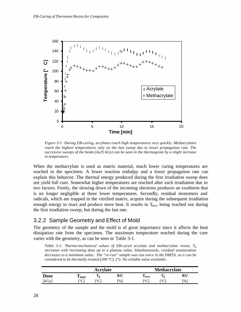
Figure 3-1: During EB-curing, acrylates reach high temperatures very quickly. Methacrylatesreach the highest temperatures only on the last sweep due to lower propagation rate. Thesuccessive sweeps of the beam (4x25 kGy) can be seen in the thermogram by a slight increasein temperature.
When the methacrylate is used as matrix material, much lower curing temperatures arereached in the specimen. A lower reaction enthalpy and a lower propagation rate canexplain this behavior. The thermal energy produced during the first irradiation sweep doesnot yield full cure. Somewhat higher temperatures are reached after each irradiation due totwo factors. Firstly, the slowing down of the incoming electrons produces an exotherm thatis no longer negligible at these lower temperatures. Secondly, residual monomers andradicals, which are trapped in the vitrified matrix, acquire during the subsequent irradiationenough energy to react and produce more heat. It results in Tmax being reached not duringthe first irradiation sweep, but during the last one.
3.2.2 Sample Geometry and Effect of MoldThe geometry of the sample and the mold is of great importance since it affects the heatdissipation rate from the specimen. The maximum temperature reached during the curevaries with the geometry, as can be seen in Table 3-1.
Table 3-1: Thermo-mechanical values of EB-cured acrylate and methacrylate resins. Tgincreases with increasing dose up to a plateau value, Simultaneously, residual unsaturationdecreases to a minimum value. The “re-run” sample was run twice in the DMTA, so it can beconsidered to be thermally treated (200 °C). (*): No reliable value available.
Acrylate MethacrylateDose Tmax Tg RU Tmax Tg RU[kGy] [°C] [°C] [%] [°C] [°C] [%]
Tem
per
atu
re [°
C]

3 -Important EB-Parameters
29
Thick samples25 150 150 13 110 156 2550 150 158 11 110 169 1875 150 159 8 110 173 16100 150 159 7 110 177 15
Thin samples25 * 81 39 * 117 5025 re-run - - - - 123 -50 * 104 25 * 130 3975 * 108 22 * 136 34100 * 117 19 * 141 32
A thin sample will cool much faster, thus decreasing the propagation rate of thepolymerization. The mobility of the reactive species is reduced in the vitrified system whythe overall curing rate decreases. The thin sample in this study is cured in an aluminummold, which, by its high heat conductivity, increases the heat dissipation rate compared to athick sample. The aluminum mold produces some heat by slowing down incomingelectrons, but this effect is negligible compared to the exotherm of the polymerization.
3.2.3 Effect of Dose and Dose RateThe Tg of the cured material increased with dose up to a plateau value, as can be seen inFigure 3-1. By analogy to thermal curing this “ultimate” Tg was called Tg∞. Full cure of theacrylate was achieved with 60 kGy, whereas the methacrylate required 80 kGy. Therefore100 kGy was used when full cure was desired in standard samples. Residual unsaturationfollowed an inverted trend, reaching 6% for the acrylate and around 12% for themethacrylate.
EB-Curing of Thermoset Resins for Composites
30
50
75
100
125
150
175
0 20 40 60 80 100 120
Dose [kGy]
10 kGy/sweep
10 kGy (fit)
20 kGy/sweep
20 kGy (fit)
25 kGy/sweep
25 kGy (fit)
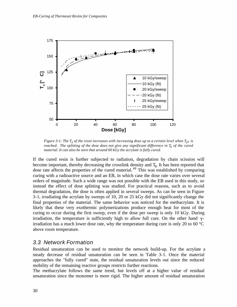
Figure 3-1: The Tg of the resin increases with increasing dose up to a certain level when Tg∞ isreached. The splitting of the dose does not give any significant difference in Tg of the curedmaterial. It can also be seen that around 60 kGy the acrylate is fully cured.
If the cured resin is further subjected to radiation, degradation by chain scission willbecome important, thereby decreasing the crosslink density and Tg. It has been reported thatdose rate affects the properties of the cured material. 48 This was established by comparingcuring with a radioactive source and an EB, in which case the dose rate varies over severalorders of magnitude. Such a wide range was not possible with the EB used in this study, soinstead the effect of dose splitting was studied. For practical reasons, such as to avoidthermal degradation, the dose is often applied in several sweeps. As can be seen in Figure3-1, irradiating the acrylate by sweeps of 10, 20 or 25 kGy did not significantly change thefinal properties of the material. The same behavior was noticed for the methacrylate. It islikely that these very exothermic polymerizations produce enough heat for most of thecuring to occur during the first sweep, even if the dose per sweep is only 10 kGy. Duringirradiation, the temperature is sufficiently high to allow full cure. On the other hand γ-irradiation has a much lower dose rate, why the temperature during cure is only 20 to 60 °Cabove room temperature.
3.3 Network FormationResidual unsaturation can be used to monitor the network build-up. For the acrylate asteady decrease of residual unsaturation can be seen in Table 3-1. Once the materialapproaches the "fully cured" state, the residual unsaturation levels out since the reducedmobility of the remaining reactive groups restricts further reactions.The methacrylate follows the same trend, but levels off at a higher value of residualunsaturation since the monomer is more rigid. The higher amount of residual unsaturation
Tg [°
C]

3 -Important EB-Parameters
31
indicates a lower crosslink density, since the monomers do not differ in size orfunctionality.
0,0
0,1
0,2
0,3
0,4
0,5
100 120 140 160 180 200
Temperature [°C]
25 kGy50 kGy75 kGy100 kGy
Figure 3-1: The EB cured acrylate in bulk has a homogeneous network, as indicated by thenarrow Tan(δ) peak. There is no significant difference between samples cured with 50, 75 or100 kGy, respectively.
The network formation can also be followed by measuring the thermo-mechanicalproperties of the cured resin. With increasing dose, the Tan(δ) peak of the acrylate,presented in Figure 3-1, is shifted to higher temperatures until the resin is fully cured. Theacrylate is partially cured when irradiated with 25 kGy, whereas full cure is almost reachedwith a dose of 50 kGy. The narrowness of the Tan(δ) peak indicates that crosslinkingreaction lead to the formation of a tight and rigid network. The curing of the acrylate resinoccurs at temperatures above the final Tg of the cured network, therefore Tg∞ is reached(c.f. Table 3-1).The methacrylate shows the same trend (c.f. Table 3-1), but as expected, reaches a higherTg since it has a more rigid backbone structure. It is worth noticing that in this case theultimate Tg is much higher than the highest temperature reached during the cure (Tmax), i.e.the crosslinking is done in the vitrified state. The broad Tan(δ) curve indicates that there aresome less crosslinked areas. These will allow some mobility in the system. The fact that forthe methacrylate resin Tg>>Tmax shows that molecular mobility plays a smaller role in EB-curing than in thermal curing, where the reaction rate rapidly slows down when vitrificationoccurs. On the other hand, the larger amount of residual unsaturation in the methacrylate(Tg>Tmax) compared to the acrylate (Tg<Tmax) indicates that although the effect of mobilityis reduced it still affects the final properties of the material.
Tan
(•
EB-Curing of Thermoset Resins for Composites
32
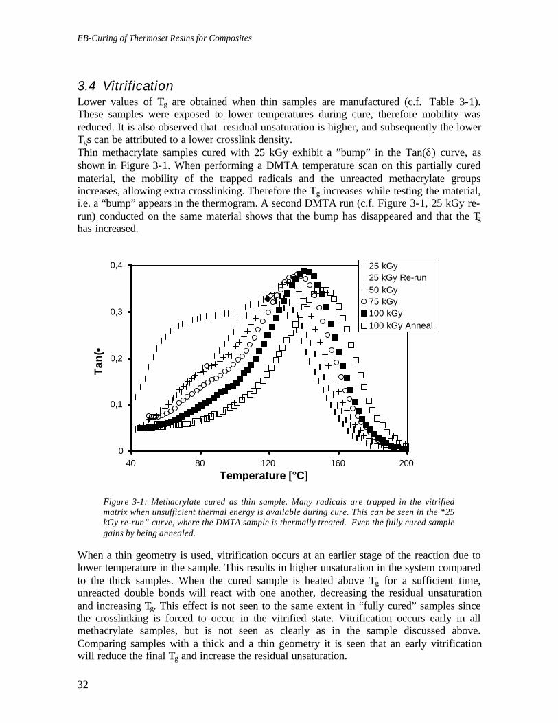
3.4 VitrificationLower values of Tg are obtained when thin samples are manufactured (c.f. Table 3-1).These samples were exposed to lower temperatures during cure, therefore mobility wasreduced. It is also observed that residual unsaturation is higher, and subsequently the lowerTgs can be attributed to a lower crosslink density.Thin methacrylate samples cured with 25 kGy exhibit a ”bump” in the Tan(δ) curve, asshown in Figure 3-1. When performing a DMTA temperature scan on this partially curedmaterial, the mobility of the trapped radicals and the unreacted methacrylate groupsincreases, allowing extra crosslinking. Therefore the Tg increases while testing the material,i.e. a “bump” appears in the thermogram. A second DMTA run (c.f. Figure 3-1, 25 kGy re-run) conducted on the same material shows that the bump has disappeared and that the Tghas increased.
0
0,1
0,2
0,3
0,4
40 80 120 160 200
Temperature [°C]
25 kGy25 kGy Re-run50 kGy75 kGy100 kGy100 kGy Anneal.
Figure 3-1: Methacrylate cured as thin sample. Many radicals are trapped in the vitrifiedmatrix when unsufficient thermal energy is available during cure. This can be seen in the “25kGy re-run” curve, where the DMTA sample is thermally treated. Even the fully cured samplegains by being annealed.
When a thin geometry is used, vitrification occurs at an earlier stage of the reaction due tolower temperature in the sample. This results in higher unsaturation in the system comparedto the thick samples. When the cured sample is heated above Tg for a sufficient time,unreacted double bonds will react with one another, decreasing the residual unsaturationand increasing Tg. This effect is not seen to the same extent in “fully cured” samples sincethe crosslinking is forced to occur in the vitrified state. Vitrification occurs early in allmethacrylate samples, but is not seen as clearly as in the sample discussed above.Comparing samples with a thick and a thin geometry it is seen that an early vitrificationwill reduce the final Tg and increase the residual unsaturation.
Tan
(•

3 -Important EB-Parameters
33


35
4 - Effect of Fibers on Matrix
The importance of the thermal history of the resin was shown in Chapter 3. Theintroduction of a new phase in the system will most likely influence this thermal history,and thereby change the final mechanical properties. In this chapter, the effect ofreinforcement fibers on temperature during cure and the mechanical properties of the curedthermoset are presented. The present chapter is based on Article 2.
4.1 Effect of the Fiber on Tmax
The value of the maximum temperature during cure (Tmax) decreased with increasing fibercontent, as can be seen in Figure 4-1. This effect was explained by lower resin fraction pervolume unit producing a smaller exotherm. The heating of the carbon fiber by the slowingdown of the incoming electrons was negligible compared to the exothermic cure. Byabsorbing locally some of the reaction heat, the fibers acted as a heat sink.The type of reinforcement fiber also influenced Tmax, as can be seen in Figure 4-2. The heatgradient in the samples was significant since the reaction occurred in the region irradiatedby the sweeping beam. Therefore the capacity of the fiber to transfer heat to cooler zonesinfluenced Tmax and the thermal history of the sample. When using the same loading ofglass fiber instead of carbon fiber, higher Tmaxs were reached. The relatively highconductivity of the carbon fiber lead to a stronger cooling of the curing zone. The higherdensity of the glass fiber, 2.5 g cm-3 compared to 1.8 g cm-3 for carbon fiber, was anotherfactor leading to higher temperatures, since more heat was produced by the slowing downof the incoming electrons.

EB-Curing of Thermoset Resins for Composites
36
0
20
40
60
80
100
120
140
160
0 2 4 6 8
Time [min]
5 wt.-% fiber10 wt.-% fiber20 wt.-% fiber30 wt.-% fiber40 wt.-% fiber50 wt.-% fiber
Figure 4-1: EB-cured acrylate reinforced by carbon fiber. Increasing the percentage of fiberdecreases the evolved energy and thereby the temperature reached during EB-cure.
0
20
40
60
80
100
120
140
160
0 2 4 6 8
Time [min]
0% fiber30% glass fiber30% C fiber
Figure 4-2: Acrylate resin 30wt.-% fiber. The nature of the fiber influences the temperaturereached during cure.
Tem
per
atu
re [°
C]
Tem
per
atu
re [°
C]

4 -Effect of Fibers on Matrix
37
When the methacrylate was used, the nature of the reinforcement fiber had less influenceon the value of Tmax. Indeed, since lower temperatures were reached, the temperaturegradient was smaller, and therefore conductivity was of less importance.
4.2 Relation between Tg and Tmax
The Tg of the crosslinked resin was also influenced by the fiber content, as seen in Figure4-1. The decrease in Tg was nearly linear for all four types of sample. The acrylate’s Tg wasless influenced by the presence of glass fiber than carbon fiber. The Tgs of the methacrylatewere barely influenced by the nature of the reinforcement fiber.
100
120
140
160
180
200
0 10 20 30 40 50 60
Fiber content [wt.-%]
Acr.- C fiberMet.- C fiberAcr.- glass fiberMet.- glass fiber
Figure 4-1: The glass transition temperature decreases linearly with increasing fiber contentirrespectively of the type of resin or fiber.
When plotting Tg versus Tmax, a linear relationship could be noticed. The results indicatedthat when higher curing temperatures were reached, the mobility and the reactivity of thereactive species increased, thereby allowing the resin to approach closer to its ”fully cured”or ”most possibly cured” state. This could clearly be seen for the methacrylate, as seen inFigure 4-2. The Tg of this resin depended linearly on the temperatures reached during cure,irrespectively of the fiber type used. Any additional thermal energy allowed for additionalcrosslinking reactions to occur, resulting in a higher Tg. The Tg of the acrylate reached aplateau level when cured with low concentrations of glass fiber, i.e. the thermal energy wassufficient to obtain the ”most possibly cured” state, or Tg∞. The deviation of carbon fiberreinforced acrylate was though to be due to air bubbles, i.e. the non heat-producing trappedair locally decreased temperature during cure.
Tg [°
C]

EB-Curing of Thermoset Resins for Composites
38
100
120
140
160
180
200
50 75 100 125 150 175 200
Tmax [°C]
Acr.- glass fiberAcr.- C fiberMet.- glass fiberMet.- C fiber
Figure 4-2: A linear correlation between Tg and Tmax can be found. The increase in Tg is true upto the value of Tg∞. Deviation of the carbon fiber reinforced acrylate is due to air bubbles .
If the heat evolution during cure was too low (and/or conductivity too high) for reachingTg∞, the Tg of the matrix linearly decreased with decreasing Tmax. This highlighted theinfluence of the choice of the mold material on the final properties of the skin of thecomposite. A strong cooling at the mold interface could give lowered Tg in the skin of thecomposite, which could increase the surface toughness. The relation between Tmax and Tg issimilar to the relation between Tcure and Tg that can be seen in thermal curing. The maindifference is that in thermal curing temperature can be directly controlled by changing thetemperature of the oven, whereas in EB-curing temperature is the consequence ofirradiation, crosslinking and environment. It is therefore more difficult to controltemperature for a given application cured by EB. Since thermal degradation is quiteunlikely, the main concern should be to ensure that all parts are submitted to temperaturesyielding Tg∞, so the entire composite has similar properties.
4.3 Network HomogeneityThe peak factor gave a description of the homogeneity of the network. A low peak factorindicated that the Tan(δ) peak was narrow, hence that the crosslink density andhomogeneity were high. A composite with a high peak factor exhibited a Tan(δ) peak,which broadens on the low temperature side. So not only the crosslink density was lower,but also its heterogeneity was higher, i.e. there was a broader spectrum of inter-crosslinkchain lengths. For both resins cured with glass fiber, the peak factor was constantindependently of the amount of fiber, as depicted in Figure 4-1. In this case, the thermalenergy was sufficient to produce a homogeneous network.
Tg [°
C]

4 -Effect of Fibers on Matrix
39
0
0,2
0,4
0,6
0,8
1
50 75 100 125 150 175 200
Tmax [°C]
Acr.- glass fiberAcr.- C fiberMet.- glass fiberMet.- C fiber
Figure 4-1: The peak factor describes the homogeneity of the network. If too little thermalenergy is available during cure, it increases dramatically. In most case, this value staysconstant.
When curing the acrylate with carbon fiber the peak factor was slightly higher butindependent of fiber content. The fiber withdrew some of the thermal energy, and hinderedthe formation of a homogeneous network. However the thermal energy provided wassufficient to reach an acceptable level of Tg and network homogeneity.In the case of the carbon fiber reinforced methacrylate, the decrease in Tmax induced animportant increase in the peak factor. This was due to the many reactive species that did nothave enough energy for reacting with another monomer or another chain end. All the looseends trapped in the polymer matrix gave a very inhomogeneous network. This was seen inthe broadening of the Tan(δ) peak at temperatures just below Tg. When the composite washeated above its Tg, as when performing a temperature scan in the DMTA, a large fractionof trapped radicals reacted with neighboring chains, thereby increasing the crosslink densityand the Tg of the polymer matrix. However, the thermo-mechanical properties of this post-cured composite were never as high as those of the same composite with sufficient thermalenergy during cure.The value of the peak factor reflected large changes in the network homogeneity, but it didnot show smaller variations.
4.4 External HeatingSamples were heated prior to cure in order to increase the mobility of reactive speciesduring cure, and try to obtain fiber reinforced resins with a Tg as high as the pure resin. So,instead of starting at room temperature the cure started around 80 °C. This resulted in Tmaxvalues being roughly 60 °C higher than for samples cured from room temperature, as canbe seen in Table 4-1.
Pea
k fa
cto
r

EB-Curing of Thermoset Resins for Composites
40
For the pure resins, major increase could be noticed neither in Tg, nor in residualunsaturation, since a dose of 100 kGy is sufficient to obtain “full cured”.But in the case of the reinforced methacrylate, a higher Tg was obtained when heating theresin. The extra heat increased the mobility of the reactive species, which allowed morecrosslinking. The Tg of the glass fiber reinforced methacrylate reached almost the samevalue as the pure resin cured from room temperature.Of course, in most cases, it would not be economically interesting to heat the composites inan oven, but the same result could be achieved by other means. Indeed using a morepowerful EB-source could compensate for a small lack of thermal energy in the bulk of thematerial; i.e. more heat would be produced in the material by the slowing down of theincoming electrons. However, this would decrease the energy output of the system. A moreeffective solution would be the addition of a highly exothermic reactive diluent to the resinin order to obtain a higher temperature during cure and a fully cured matrix.
Table 4-1: Effect of heating prior to EB-curing. The higher start temperature increased thethermo-mechanical properties of the fiber reinforced polymer matrix.
Sample Start temperature Tmax Tg[°C] [°C] [°C]
EB 600Pure 25 150 159Pure, heated 83 203 164
EB 610Pure 25 121 178+ glass fiber 25 92 146+ carbon fiber 25 100 142
Pure, heated 83 165 182+ glass fiber, heated 69 134 174+ carbon fiber, heated 77 115 167
The amount and type of fiber influences the thermo-mechanical properties of the resin bychanging the thermal history of the sample. If there is a lack of heat during cure, thereactive species get trapped in the vitrified matrix. A post-cure can allow to somewhatincrease the crosslink density.
41
5 - Radiation vs. Thermal Curing
Radiation and thermal curing were compared to highlight differences and similarities. Sincelimited information about EB-curing of composites is available, it is interesting to know thesimilarities with thermal and UV-curing in order to take advantage of the knowledgeavailable in these fields. Thermal curing is very well documented and has been used formany years for curing composites. UV-curing is frequently used in the coating industry andis starting to find some niche applications in composites.The prevailing idea was to cure samples with the same geometry “as well as possible” withthe different curing techniques, and to compare their thermo-mechanical properties. It isbeyond the scope of this discussion to compare the energy needed to obtain full cure, sinceit is too dependent on the technique and equipment used. The most important curingparameters are the temperature reached in the resin (thermal history) and the time neededfor a full cure.It is known from thermal curing that the Tg of the cured resin is dependent on thetemperature reached during cure.12 When the resin comes in the vitrified state, the rate ofpropagation drops. The initiator type and concentration were chosen with the intention tohave similar thermal histories of the resins. The thermal history of EB-curing was taken asa yardstick. This chapter is based on the results presented in Article 3.
5.1 Optimization of Cure Systems
UV-CuringFor thick samples it is necessary to use a photo-bleaching photoinitiator, i.e. an initiator thatdoes not significantly absorb in the UV range once it has degraded into the initiatingproducts.49 Otherwise only the surface cures since all the UV light is absorbed there. Acomparison between different samples showed that the optimum initiator concentration was3 wt.-%. This resulted in a maximum Tg and a minimum residual unsaturation. When using1 wt.-% initiator, the resin was not fully cured, as can be seen in Table 5-1. The use of 5wt.-% initiator did not result in improved thermo-mechanical properties.
Table 5-1: Comparison of EB, UV and thermally cured acrylate and methacrylate resin.
Toven Initiator Tmax Ts Tg Ts/Tg RU[°C] [wt.-%] [°C] [°C] [°C] [wt.-%]
AcrylateEB - 150 142 159 0.961 6

EB-Curing of Thermoset Resins for Composites
42
UV 1 111 52 81 0.918 333 119 61 93 0.913 195 123 61 92 0.915 14
Thermal 90 2 238 120 141 0.949 <590 4 255 98 115 0.956 <5110 0.5 243 129 148 0.955 7110 2 249 105 131 0.936 5110 4 264 100 120 0.949 <5
Methacrylate
EB - 110 157 177 0.956 15UV 1 80 62 110 0.875 29
3 92 71 118 0.880 205 94 77 123 0.884 15
Thermal 90 2 162 135 172 0.917 1090 4 161 127 155 0.935 <5110 0.5 171 144 171 0.939 13110 2 143 123 150 0.936 8110 4 155 - - - <5
Thermal CuringThe samples cured with 0.5 wt.-% initiator at 110 °C were selected, since the highest Tg
was achieved with this system. Some of the other samples had somewhat lower residualunsaturation but also lower Tg. It is suggested that the high initiator concentration increasesthe amount of chain transfer and the termination rate, leading to reduced Tgs. The very hightemperature reached during cure allowed almost full conversion of the double bonds. Thecracking and yellowing of the samples increased with increasing initiator content.
5.2 Cure of Resin
EB-CuringAs seen previously, EB-curing is extremely fast and accompanied by a strong temperatureincrease, as seen in Figure 5-1. For the acrylate resin, the highest temperature was reachedduring the first sweep of the beam that is after a few minutes. For the methacrylate resin,
emp
erat
ure

5 -Radiation vs. Thermal Curing
43
the temperature increased during each sweep because of a measurable reaction exotherm.
0
50
100
150
200
250
0 15 30 45 60 75 90
Time [min]
Therm. AcrylateTherm. Metacr.UV AcrylateUV Methacr.EB AcrylateEB Methacr.
Figure 5-1: Thermogram during EB, UV and thermal cure of both the acrylate and themethacrylate. It can be seen that thermal curing reaches much higher temperatures andrequires much longer curing times.
UV-CuringDuring UV-cure, both resins reacted in a similar way. The temperature rise was slower thanwith EB (c.f. Figure 5-1), since propagation rate was limited by the photobleaching rate ofthe initiator. The target molecules (initiator) absorbed the UV-energy and underwent bondcleavage, producing initiating species. There was no significant heat increase due to theincident UV-radiation. Only a slight heating due to the IR-radiation of the lamp. The UV-induced reaction propagated slowly through the sample, which left more time for thermaldiffusion. Therefore Tmax, and consequently the mobility of the reactive species, were lowerthan in the case of EB-curing. The temperature reached a maximum value, and than slowlydecreased. Tmax was 20-30 °C lower than the value obtained with EB.
Thermal CuringFor thermal cure the induction time was very long (c.f. Figure 5-1). Indeed, about one hourwas needed for the sample to reach oven temperature and for a reaction exotherm to bedetectable. Once the reaction began, the extra heat caused more initiator to decompose,hence more heat and radicals to be produced. Consequently the reaction underwent auto-acceleration. It is known that acrylic resins undergo Tromsdorff effect when iso-thermallycured. In these thick samples there was no sufficient time for dissipating quickly enoughthe heat in order to avoid high temperatures. Since the reaction started at 110 °C, Tmax forthe thermally cured resins was extremely high. The acrylate reached 243 °C, whereas themethacrylate reached 171 °C. When changing oven temperature, the time when auto-acceleration occurred varied, but the strength of the exotherm was unchanged. It was notpossible to use a lower temperature initiator because of thermal stability. The resin needed

EB-Curing of Thermoset Resins for Composites
44
to be heated to 70 °C in order to lower the viscosity during mixing and then to evaporatethe solvent.
5.3 Comparison of Cured Samples
EB-CuringWhen EB was used to cure the two resins investigated in this study high Tgs and lowamounts of residual unsaturation were obtained (c.f. Table 5-1). The narrow Tan(δ) peak,as seen in Figure 5-1, indicates a homogeneous network. Relatively high temperaturescombined with a high and homogenous radical concentration during cure could explain thishomogeneity. The highly energetic radiation also produces radicals on the main chain byhydrogen abstraction. This mechanism, called grafting, is specific to EB-curing. It allowsfor extra crosslinking possibilities compared to thermal and UV-curing. The Tg was slightly(acrylate) or much higher (methacrylate) than the Tmax, hence the reaction occurred in thevitrified state. EB samples were often slightly yellow. This color was due to trappedradicals that disappeared after heating above Tg.
UV CuringThe UV-cured samples exhibited low Tgs and a fairly high amount of residual unsaturation(c.f. Table 5-1). The Tan(δ) peaks were also broader than for the EB-cured samples (c.f.Figure 5-1), giving higher Ts/Tg ratios. The methacrylate had very broad peaks, whichcould be explained by a low Tmax limiting the reaction to reach the fully cured state. Insome samples, e.g. 1 wt.-% initiator, post-curing was clearly visible when performing theDMTA measurements. The acrylate had a Tg 30 °C under Tmax, whereas the methacrylatehad a Tg 30 °C above Tmax. The low Tmax did not allow for sufficient mobility during cureand therefore the UV-cured resin, especially the methacrylate, was somewhat undercuredcompared to its EB counterpart. The top of the UV samples was yellow, since such thicksamples required a high UV dose to obtain a full cure throughout the sample. The color wasprobably due to degradation of the surface.
Tan
(•

5 -Radiation vs. Thermal Curing
45
0
0,1
0,2
0,3
0,4
25 50 75 100 125 150 175 200 225 250
Temperature [°C]
Therm. AcrylateTherm. Methacr.UV AcrylateUV Methacr.EB AcrylateEB Methacr.
Figure 5-1: Tan(δ) curves of EB, UV and thermally cured acrylate and methacrylate resins.Tgs obtained by UV curing in bulk are significantly lower.
The main advantage of the UV process is the simplicity of the equipment and of theprotection needed. This, combined with a relatively short curing time, allows the use of thistechnique for repairing large composite structures. From this point of view it is important toknow how the properties of the UV-repair compares to those of the original EB- or thermal-cured composite. To be efficiently UV-cured, the two resins used in this study could beblended with a more exothermic monomer that would be included in the polymer network.The extra heat would allow the curing reaction to proceed closer to completion, and thethermo-mechanical properties of the repair material to be more similar to the originalmaterial.
Thermal CuringThe thermally cured samples underwent auto-acceleration (c.f. Figure 5-1). The thermallycured samples exhibited Tgs and Tan(δ) peaks similar to those of the EB-cured samples (c.f.Figure 5-1), and even lower residual unsaturation (c.f. Table 5-1).For the acrylate samples Tmax was much higher than Tg. The high mobility during cureallowed very high conversion of the double bonds, why high crosslink density and high Tgwere achieved.The methacrylate reached Tgs fairly close to Tmax. It was noticed that increasing initiatorconcentration lead to a slight decrease in residual unsaturation and a significant decrease inTg. In the presence of such a large amount of initiator, more double bonds will react, butmany chains will be terminated instead of being crosslinked to the polymer network.11
Oven temperature did not influence the Tg since the exotherm was so strong. Thepolymerization was more influenced by the Tmax value, which was directly dependant on

EB-Curing of Thermoset Resins for Composites
46
the reaction exotherm. The temperatures during cure were so high that the reaction neveroccurred in the vitrified state. It must be mentioned that the thermally cured resins cracked,probably due to the thermal chock that occurred during the auto-acceleration. Theyellowing of the samples increased with increasing cure temperature and increasinginitiator concentration.
5.4 Comparison of CompositesAs shown in Chapter 3, the temperature reached during cure influenced the networkhomogeneity and the Tg of the matrix. Glass fiber added to the resin can be seen as an inertmaterial that acts like a heat sink, as opposed to the exothermic resin. Therefore the heatovershoot, produced by the radiation or the reacting resin, must compensate for the loweroverall heat generation in order to obtain full cure.
EB-CureAddition of a non-reacting material (fiber) to the strongly exothermic acrylate, did noteffect the Tg of the cured matrix, i.e. the overall exotherm was sufficient for Tg∞ to bereached, as seen in Table 5-1.The glass-fiber reinforced methacrylate exhibited a decrease in Tmax, why the cure had toproceed in the vitrified state and Tg was reduced.
UV-CureWhen UV-cured, both resins reached very low Tgs. This was not much of a surprise sincethe cure of the pure resins already proceeded in the vitrified state.
Thermal CureThe thermally cured acrylate had such a thermal overshoot that the temperature was highenough to obtain fully cured samples in spite of the presence of fibers. The methacrylatewas more prone to vitrification since Tmax was close to Tg. The thermal overshoot could notcompensate fully for decrease in heat production, and therefore the value of Tg showed aslight decrease.
Table 5-1: Comparison of EB, UV and thermally cured glass fiber reinforced (30 wt.%)composites. ∆Tg is the difference between the Tg of the pure resin (c.f. Table 5.1) and the Tg ofthe fiber reinforced resin
Toven Initiator Tmax Ts Tg ∆∆Tg Ts/Tg RU[°C] [wt.-%] [°C] [°C] [°C] [°C] [%]
AcrylateEB - 109 133 161 2 0,937 14UV 3 65 43 67 -26 0,929 34
Thermal 110 0,5 252 128 150 2 0,948 5
MethacrylateEB - 92 126 145 -22 0,953 13UV 3 59 61 105 -13 0,884 27
Thermal 110 0,5 179 117 162 -9 0,897 12
5 -Radiation vs. Thermal Curing
47
To summarize it can be said that EBs allow to cure quickly thick acrylic composites atreasonably high temperature. High thermo-mechanical properties are reached. Very littleheat is produced during UV-curing, which can be a problem when higher temperatures areneeded to reach full cure. UV-curing is inhomogeneous since an additive is needed foracrylic resins and the reaction slowly propagates through the composite as the initiatorbleaches. Thermal curing of thick layers of acrylic resins has practical limitations, sinceauto-acceleration of the reaction can lead to thermal degradation. It is also much more timeconsuming than EB-curing.Surprisingly, the thermal history during cure has much more influence on the properties ofthe sample than the curing technique.

EB-Curing of Thermoset Resins for Composites
48

49
6 - Matrix Toughening
Brittleness of composites is an important issue. Toughening systems must be adapted toEB-curing in order to combine high modulus and tolerance towards impact damage. Toachieve this, a two-phase resin is desired, such as a matrix, giving high modulus and highTg, and a rubbery additive, increasing toughness of the system by increasing the energyrequired for the crack propagation. 50,51 For applications where fibers are impregnated, it ispreferable to use a liquid-liquid emulsion in order to avoid filtering of rubbery particles.Some very nice work has been done on the toughening of thermally cured epoxy resins byhaving a reaction induced phase separation. 52,53 A fully miscible liquid-liquid mixture phaseseparates during cure since epoxies undergo a large change in polarity when crosslinking.A series of toughening additives were synthesized and tested. The additives, based on anhyperbranched aliphatic polyester, were functionalized with various end-groups to controlphase separation and crosslinking. Alkyl chains of different lengths were attached to thescaffold controlled phase separation. Crosslinking was realized by the attachedmethacrylate groups. The results presented here are taken from Article 4 and 5.
6.1 Synthesis and BlendingThe hyperbranched polyester used in this study is a convenient scaffold since its terminalhydroxyl groups are numerous and accessible. It was functionalized with moieties thatallowed controlled phase separation and crosslinking of the additive (c.f. Figure 2-1, Table2-1). The fraction and the length of the alkyl chains changed the polarity of the additive,thereby affecting the phase separation. Crosslinking was controlled by the percentage ofmethacrylate groups reacted on the hyperbranched scaffold.To mix the acrylate and the additive, it was necessary to add solvent in order to reduce theviscosity. The use of dichloromethane and diethylether was investigated. The phaseseparation worked well when using dichloromethane, but complete removal of the solventrequired high vacuum that strongly increased the risk for premature gelling. Residualdichloromethane also turned out to be a disadvantage when EB-curing the resin, sincechlorinated compounds are effective radical scavengers. Small amounts of residual solventstrongly affected curing, which resulted in a broadened Tan(δ) peak and a decreased Tg, ascan be seen when comparing sample V and V* in Table 6-1. Diethylether was preferredbecause of its lower boiling point.

EB-Curing of Thermoset Resins for Composites
50
6.2 Phase separationUnfortunately reaction induced phase separation, as performed by Boogh et al.,52 is notpossible in EB since the cure process is too fast. Moreover the polarity of acrylates does notchange during the cure as it does for epoxies.The phase-separation of the acrylate and the hyperbranched additive was governed byseveral factors. First, the viscosity had to be lowered by adding solvent. But on the otherhand, solvent had to be evaporated in order to obtain a phase separation. A compromisewas found by evaporating the solvent until the resin had a syrup-like consistence. Thephase separation first gave very small particles, which were too small to give an increase intoughness. Time was the second factor. It was not only necessary for the phase separationto occur, but also for the particles to mature, or grow to a size in the micron range.The polarity difference between the resin and the additive was the third factor. The alkylchains attached to the hyperbranched additive acted like a non-polar shell. The drivingforce to have a fully phase separated emulsion increased with a lowered polarity of theadditive, as can be seen in Figure 6-1. The relative amount of alkyl chains and methacrylatemoieties grafted on the hyperbranched also influenced the phase separation since it changedthe polarity of the additive. The molecules with the highest proportion of alkyl chainsphase-separated easier and resulted in larger particles. Once the remaining solventevaporated, the phase-separated resin was very stable. Indeed, samples kept at roomtemperature for 18 months neither gelled, nor exhibited a significant increase in particlesize. The high viscosity of both components was thought to contribute to the stability of theresins.
Figure 6-1: Phase separation in resins VIII-X, containing 5 wt.-% additive with 40%methacrylate groups and C6, C8 and C10 alkyl chains. The decreasing polarity of the additive,from left to right, gives an increased phase separation after 12 h.

6 -Matrix Toughening
51
6.3 Cured additiveThe pure hyperbranched additives were cured in order to investigate its mechanicalproperties. All samples were rubbery and quite, or very, fragile when submitted to traction.Two trends could be observed. First, when increasing the length of the alkyl chains, themechanical properties dropped, probably due to the high amount of dangling alkyl ends.Second, with more than 40% methacrylate groups, the hyperbranched thermoset startedloosing its rubbery properties. To try to circumvent the problem of the dangling ends, analkyl chain with a terminal double bond (10-undecenoate) was reacted onto thehyperbranched scaffold (additives 5, 9). The long alkyl chain gave very good phaseseparation, and the modulus of the cured additive was increased, i.e. with similar degrees ofmethacrylation the additive with the unsaturated alkyl gave slightly higher modulus thanthe additive with C8-chains. However, the FT-Raman spectra showed some unreactedterminal double bonds. Hence, these fairly stable double bonds were only partially reactedwhen EB-irradiated.
6.4 Cured resinCuring of the acrylate-hyperbranched additive blend occurred by a free-radical mechanism.The temperature reached during cure was around 155 °C. Most of the curing took placeduring the first 20 s, when the maximum temperature was reached. The short time framedid allow a diffusion process to take place in these viscous resins. Furthermore, sincegelation occurs very early (5-10% conversion) in acrylates,22 no significant viscosity dropcould take place at high temperatures. As a result, the particle size and the particledistribution were similar before and after cure, as seen with optical microscopy.
Table 6-1: Mechanical testing of acrylate resins toughened with functionalized hyperbranchedpolyester. Star marked (*) samples were mixed in diethylether.
Sample Additive Ts Tg Ts/Tg RU KICType wt.-% [°C] [°C] %
MPa m ±
0 - - 136 154 0.958 7 0.38 0.05I 1 2.5 96 117 0.947 6 - -II 1 5 92 113 0.944 7 - -III 2 5 97 118 0.948 6 - -IV 3 2.5 100 120 0.947 6 - -V 3 5 101 120 0.950 5 0.44 0.04V* 3 5 112 135 0.944 5 0.54 0.08VI 4 5 104 124 0.949 5 0.47 0.02
VII* 5 5 122 142 0.952 6 0.47 0.02VIII 6 5 127 146 0.953 6 - -IX 7 5 107 127 0.950 7 - -X 8 5 120 141 0.951 6 - -
XI* 9 5 112 132 0.950 6 0.48 0.06
The Tg -values for the cured pure resin and the cured toughened resin were fairly similar.The drop in Tg was between 10 and 20 °C, given that the solution phase separated properly,and that the remaining solvent did not inhibit the crosslinking reaction (samples V*, VII*and XI*). If one of the two last conditions was not fulfilled (samples V and IX, residualdichloromethane), the value of Tg easily dropped by 35 to 40 °C. Samples containing an

EB-Curing of Thermoset Resins for Composites
52
additive with a low fraction of crosslinkable groups and long alkyl chains (samples I-VI)usually had lower thermo-mechanical properties. If the percentage of methacrylate groupson the additive was high enough (samples VII-X), this risk was decreased. Samples withlong, unsaturated alkyl chains (VII* and XI*) had fairly high Tgs and narrow Tan(δ) peaks.This indicates that these terminal unsaturations are partially reacted and connected to thenetwork. Hence a good and fast phase separation was realized without decreasing thethermo-mechanical properties. Using only 2.5 wt.-% additive did not give any noticeablechanges in Tg or Tan(δ), maybe because the residual solvent had a stronger effect than thissmall amount of additive did.Residual unsaturation was around 6%, hence in the same range as the pure acrylate, for allsamples. This seems to indicate that in samples with low Tgs, the radicals reacted withsomething else than the polymer network, most likely with oxygen or solvent molecules.Thus giving dangling ends, hence a less crosslinked network and a broader Tan(δ) peak.
6.5 ToughnessAn increase in toughness could be seen between samples 0, V and VI. Longer alkylmoieties on the hyperbranched additive resulted in higher KIC values. It seems like thelonger chains allow more plastic deformation of the rubbery particles in the brittle acrylatematrix. Samples with the long alkene chains (VII* and XI*) gave most toughening. At thesame time, their terminal double bonds allowed them to crosslink to the matrix, therebymaintaining a high value of Tg.The enormous difference between the samples prepared with dichloromethane (V) and withether (V*) was more puzzling. An increase in toughness for the samples blended in etherwas expected, since phase separation was better and solvent evaporation was easier. It wasnoticed that prior to curing, some domains had gelled, and that the dispersion of the erroron KIC was quite high. One explanation could be that gelation prior to cure created somefairly large domains of “soft matter”, which could not be cured to the same extend as therest of the resin when irradiated. Hence a macro two-phased sample was produced, yieldinginhomogeneous properties.
It was shown that it is possible to toughen EB-cured resins by having a phase separatedsystem. Phase separation was induced by the alkyl chains grafted on the hyperbranchedpolyester used as an additive. The methacrylate moities allowed to crosslink the additive.Since EB-curing is a rapid process, phase separation had to be realized prior to curing. Thechoice of the solvent used for mixing the resin and the additive influenced the properties ofthe cured toughened polymer.

6 -Matrix Toughening
53


55
7 - Conclusions
EB-curing of the acrylates and methacrylates used in this study is a free-radicalpolymerization process. For both resins, the Tg increases with increasing dose up to aplateau level, after which no significant increase in Tg can be noticed when furtherincreasing the dose. The monomers differ by their reactivity and their mobility in thecrosslinking network.The most important factor when EB-curing a thermoset resin was the thermal history of thesample during cure. The reaction rate and exotherm of the polymer resin, as well as theenergy of the EB, determined the thermal energy that will be available during cure. Thisenergy had to be sufficient to reach full cure, else Tg linearly decreased with decreasingtemperature during cure. If the heat dissipation during irradiation, by a mold for example,was too strong, the reactive species got caught in the vitrified network. Upon heating, theserecombined or reacted, thereby changing the properties of the network.The fiber type and content also affected the properties of EB-cured composites. Anincreasing amount of fiber lowered Tmax, since there was less material producing heatduring cure. The thermal conduction of the fiber played an important role, since in EB-curing the heating is local and leads to thermal gradients. The combination of a mildlyexothermic resin and a highly heat conducting fiber, methacrylate/carbon fiber, gave verylow temperatures in the resin and therefore an undercured polymer matrix.EB-curing of acrylic resins via free-radical polymerization was compared to UV- andthermal curing. EB- and thermal curing gave highly crosslinked and homogeneousnetworks. In EB-curing, grafting allows additional crosslinking possibilities, therebyincreasing crosslink density. The main advantages of EB-curing were the relative short timeneeded tor obtain full cure and the not too high temperatures during cure, thus avoidingthermal degradation. The thermal process suffered from the high temperature reachedduring cure, due to the auto-acceleration of the reaction. In UV curing, the lowertemperature reached during cure hindered the reaction from proceeding as completely aswhen using thermal- or EB-curing.A method for toughening EB-cured acrylate resins was developed. The additive, ahyperbranched polyesters, was functionalized to control phase-separation and crosslinking.A series of additives with different percentage of methacrylate groups and different lengthof alkyl chain was synthesized and investigated. The blends were optimized to obtain amaximum phase-separation and a minimized decrease in Tg. Curing of these phase-separated resins was readily achieved, and the hyperbranched additive only caused a smalldecrease in the thermo-mechanical properties of the resin. Finally an increase in toughnesscould be seen.

EB-Curing of Thermoset Resins for Composites
56

7 -Conclusions
57


59
Acknowledgments
I express my sincere gratitude to my supervisor, Professor Anders Hult, for accepting me ashis student and for giving me the opportunity to work on a very interesting project. He alsogave me the chance to discover some of Europe’s less known wonders such as Bordeaux’sfishing-gear affair, Lyon’s croissant-jacuzzi, Aix-en-Provence’s techno club, Marseilles’sfree-ways, Brussels’s “Le Cercueil”, the Pope in Vienna, Munich’s Schweinaxel, Le Doyenin Paris, Stockholm’s Extract and Åre’s korvkiosk.Professor Ann-Christine Albertsson, Professor Ulf Gedde, Professor Sigbritt Karlsson, thelate Professor Jan-Fredrik Jansson and Associate Professor Bengt Stenberg areacknowledged for building-up a scientifically stimulating environment at the department ofPolymer Technology. I also thank Margaretha Andersson, Charlotte Warding, MariaBozena Anderz and Birgitta Asker for helping through KTH’s administrative maze. Goodluck Ove with the department’s network and PC’s.I am very thankful to Professor Torbjörn Reitberger for his interesting discussions aboutradiation chemistry and history.
The Council of the European Community (CEC) is gratefully thanked for sponsoring thisstudy via a Brite-Euram project, BE 951449-Technicopolis. UCB is acknowledged forsupplying us with resins. Aerospatiale and the other Technicopolis members are thankedfor their support and the constructive debates.
I owe a dept of gratitude to the people who supported me technically: Kjell EB-masterOlsson, Jakob Lay-up Kuttenkeuler, Xavier Tough(ness) Guy Kormann and Jean-Claudethe Brewer Vanovervelt.
Thank you, Cissi, Jakob, Nicke, Helene, Jonas, Tommy and Johan for the great atmospherein the Hult groupe. Micke and Fredrik, you opened the doors to Stockholm’s darker side,and you have a big responsibility for me staying here! Creatin-Hasse, Habib-Michael andSlitz-Peter it is great you brought some new blood to the group. Keep it rocking and rolling!Sorry, Andreas but you will have to find someone else to discuss the joys of calibrating theDMTA. Linda, our sunflower, keep your stinky chemistry away. Thank you Eva for takingthe time to “do only a few corrections” and for making things happen in this department.Farbror Mats, how patient and tolerant you have been with me during all these years! Ireally appreciated your company and help during this 5-year walk through science.A very special though to present and former ABB members, who made this departmentcozy and crazy. More specifically to Waltzing Kajsa, Petter Mr. Nice Guy, Martin the

EB-Curing of Thermoset Resins for Composites
60
Stripper, Gustav the Whacko, Micke Bob-the-Sloppy-Slave. And last but definitely notleast, Segling- Salto-Skidor-Sup Karin.Finally I would also like to thank all undergraduate and graduate students who made thisdepartment a pleasant place to work.
My warmest thanks to the French Gang for their support and for all the great times spenttogether, Vikingarännet Claire et ses débauches caloriques, Didier-le-Sudiste qui“challenge” les corniches de la mort, Mina-bög-kompisar Manu et son Verbe Puissant etAbondant, Petit Rose Olivier et son accent de chez nous, et finalement Champion-du-Monde-de-Motocyclettes-à-Ressort Phil et ses pêches miraculeuses sur les plagesbalinaises. And of course the temporary members You-are-so-Silly Philou, ChampagneSonia, la P’tite Soph’ and Flamenco Queen Céline.Of course I do not forget the foreign members of the gang: Cheesy Sunglasses Ronnie witha right to five minutes, and Mother in Law Dream Henrik with all the right stuff.Thank you Birgitta, Cindy and Carin for being there, and NOT being at the department.Christophe d’Aquapub, Bertrand de Steffisburg-bei-Thun and Anne du Greffe, you arefantastic friends and the spice of life.
Finally I would like to thank my family, Pierre, Madeleine and Didier, for their support andall the wonderful moments we have had together.

61
References
1 Charlesby A. Atomic Radiation ond Polymers, Pergamon Press, Oxford, 19602 Charlesby, A. Radiat. Phys. Chem., 1991, 37(1), 5
3 Chapiro A. Radiation Chemistry of Polymeric Systems, Interscience, New York, 19624 Spinks, J. W. T. and Woods, R. J. An Introduction to Radiation Chemistry, Third Ed., John Wiley & Sons
Inc., New York, 19905 Ivanov V.S., Radiation Chemistry of Polymers, VSP BV, Utrecht, 19926 Mehnert R., Nuclear Instruments and Methods in Physics Research B, 105, 348-358, 19957 Gehringer P., Proksch E. and Eschweiler H., Proc. Int. Symp. on High-Dose Dosimetry, Int. Atomic Energy
Agency, 8-12th October 1984, Vienna8 Mark H.F., Encyclopedia of Polymer Science and Engineering , Vol. 4, John Wiley & Sons Inc., New York,
19869 Baekeland L., J. Ind. Eng. Chem., 1909, 1, 14910 Odian G., Principles of Polymerization, 3rd Ed., John Wiley & Sons, New York, 199111 (a) Lange J., Curing of Thermoset Films: Build-Up of Structure and Residual Stresses, Ph.D. Thesis, Royal
Institute of Technology, Stockholm, 1995
(b) Lange J., Toll S., Hult A., Månson J.-A.E., Polymer, 1995 35, 3135
(c) Lange J., Hult A., Månson J.-A.E., Polymer, 1996 37, 5859
(c) Lange J., Toll S., Hult A., Månson J.-A.E., Polymer, 1997 38, 809
(d) Lange J., Johansson M., Kelly C.T., Halley P.J., Polymer , 1999, 40, 569912 (a) Enns J., Gillham J.K. J. Appl. Polym. Sci., 1983, 28, 2567
(b) Gillham J.K., Polym. Eng. and Sci., 1986, 26, 20
(c) Wisanrakkit G., Gillham J.K. J. Appl. Polym. Sci, 1990,41, 2885
(d) Wisanrakkit G., Gillham J.K. J. Appl. Polym. Sci, 1991, 42, 2453
(e) Simon S.L., Gillham J.K. J. Appl. Polym. Sci, 1994,51, 174113 Roffey C.G., Photopolymerization of Surface Coatings, John Wiley & Sons, New York, 198214 Kloosterboer J.G., Network Formation by Chain Crosslinking Photopolymerization and its Applications in
Electronics, Adv. in Polym. Sci. 84, Springer-Verlag, Berlin, 198815 Pasternack G., J. of Radiation Curing, 1982, July, 12

EB-Curing of Thermoset Resins for Composites
62
16 Brandrup J., Immergut E. H. Polymer handbook, 3rd Ed., John Wiley & Sons, New York, 1989
17 van Krevelen D. W., Properties of Polymers, 3rd Ed. Elsevier, London,199018 Carey F.A., Advanced Organic Chemistry, 2nd Ed., Plenum Press, New York, 198419 Schultz A.R., Bovey F.A., J. Polymer Science, 1956, (22), 48520 Takács E., Wojnárovits L., Nucl. Inst. Meth. Phys. Res. B , 1997, 131, 29521 Knolle W. , Mehnert R., Nucl. Inst. Meth. Phys. Res. B, 1995, 105, 15422 McGinnis V. D., Encyclopedia of Polymer Science and Engineering, Vol4, Ed. Kroschwitz J. I., John
Wiley & Sons, New York,198623 Mishra M.K. and Kobayashi S., Star and Hyperbranched Polymers, Marcel Dekker Inc., Basel, 199924 Newkome G.R., Moorefield C., Vögtle F., Dendritic Molecules: Concepts, Synthesis, Perspectives, VCH
Verlagsgesellschaft , Weinheim, 199625 Flory P.J., J. Am. Chem. Soc., 1952, 75, 271826 Tomalia D.A., Baker H., Dewald J., Hall M., Kallos G., Martin J.R., Ryder J., Smith P., P. Polym. J., 1985,
17, 11727 Newkome G.R., Hu Y., Saunders M.J., Fronzek F.R., Tetrahedron Lett., 1991, 32, 113328 Fréchet J.M.J., Hawker C.J., Wooley K.L., J.M.S. Pure Appl. Chem., 1994, A31, 1627-164529 a) Malmström E., Hyperbranched Aliphatic Polyesters, Ph.D. Thesis, Royal Institute of Technology,
Stockholm, 1996
b) Ihre H., Synthesis and Characterization of Dendritic Macromolecules…, Ph.D. Thesis, Royal Institute ofTechnology, Stockholm, 1998
30 Perstorp Polyols, Perstorp AB, Sweden31 Malmström E., Johansson M., Hult A., Macromol. Chem. Phys., 1996, 197, 319932 Johansson M, Glauser T.,Rospo G., Hult A., J. Appl. Polym. Sci., accepted for publication33 a) Shi W., Rånby B., J. Appl. Polym. Sci.,1996, 59, 1937
b) Shi W., Rånby B., J. Appl. Polym. Sci.,1996, 59, 1945
c) Shi W., Rånby B., J. Appl. Polym. Sci.,1996, 59, 195134 Åström B.T., Manufacturing of Polymer Composites, Chapman & Hall, London, 199735 Saunders, C. B., Lopata, V. J., Kremers, W., Chung, M., Singh, A. and Kerluke , D. R. Radiat. Phys.
Chem., 1995, 46(4-6), 99136 Saunders, C. B., Singh, A., Lopata, V. J., Kremers, W. and Tateishi, M. ACS Symp. Ser. 1993, 527, 30537 Singh, A., Saunders, C. B., Barnard, J. W., Lopata, V. J., Kremers, W., McDougall, T. E., Chung, M. and
Tateishi, M. Radiat. Phys. Chem, 1996, 48(2),15338 Devney B.G., Vizzini A.J., Chappas W.J., Proc. of Int. SAMPE Techn. Conf., November 4-7, 199639 Vendroux, G., Hocquellet, M., Boursereau, F. and Dourthe, P. RadTech Europe 97, conference
proceedings, 1997, 46240 Béziers, D., Perilleux, P. and Grenie, Y. Radiat. Phys. Chem., 1996, 48(2) 17141 Crivello J.V., Walton T.C. and Malik R. Chem. Mater. 1997, 9, 127342 (a)P.E. Sundell, Cationic Polymerization of Vinyl Ethers Using Iodonium and Sulfonium Salts, Ph.D.
Thesis, Royal Institute of Technology, Stockholm, 1-10 (1990)

References
63
(b) P.E. Sundell, S.E. Jönsson and A. Hult, Radiation Curing of Polymeric Materials, ACS Symp. Ser.417,Eds. Hoyle C.E., Kinstle J.F., Washington DC, 1990, Ch. 32
(c) E. Malmström, P.E. Sundell, A. Hult, S.E. Jönsson, Nucl. Inst. and Meth. in Phys. Res. B , 1995, 105,168-174
43 E. Malmström, M. Trollsås, C. J. Hawker, M. Johansson, and A. Hult, Polym. Mater. Sci. Eng., 77(2), 151(1997)
44 (a) E. Malmström, M. Johansson, and A. Hult, Macromolecules, 28, 1698 (1995)
(b) A. Hult, M. Johansson, E. Malmström, and K. Sörensen, WO 93/17060, (1993)45 Vijaykumar Narayanan, K.K. Baikerikar, A.B. Scranton, Proceedings of Radtech’98, 19-22th April 1998,
Chicago46 Nielsen L.E., Landel R.L., Mechanical Properties of Polymers and Composites, 2nd Ed. Marcel Dekker,
New York, 199447 Patacz C. et al., Proc. of RadTech Europe 97, 8th Conf. on Radiat. Curing, June 17-18th 199748 Hayachi K., Takezaki J., Okada T. and Sakurada I., J. of Appl. Pol. Sci., 36, 295, 198849 Jacobi M. and Henne A., J. of Radiation. Curing, Oct 1983,16-2250 (a) Riew C.K., Kinloch A.J., Toughened Plastics I, Adv. Chem. Ser. 233,1992
(b) Riew C.K., Kinloch A.J., Toughened Plastics II, Adv. Chem. Ser. 252,199651 Janke C.J., Dorsey G.F., Havens S.J., Lopata V.J., Proc. of Int. SAMPE Techn. Conf. , November 4-7, 199652 L. Boogh, B. Pettersson and J.-A. Månson, Polymer, 40, 2249 (1999)53 Wu H., Xu J., Liu P., Heiden P., J. Appl. Polym. Sci., 72, 151 (1999)