Embed Size (px)
Citation preview
Electromagnetic Waves
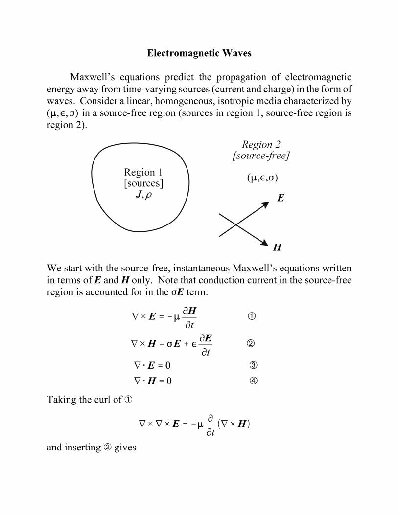
Maxwell’s equations predict the propagation of electromagneticenergy away from time-varying sources (current and charge) in the form ofwaves. Consider a linear, homogeneous, isotropic media characterized by(:,,,F) in a source-free region (sources in region 1, source-free region isregion 2).
We start with the source-free, instantaneous Maxwell’s equations writtenin terms of E and H only. Note that conduction current in the source-freeregion is accounted for in the FE term.
Taking the curl of â
and inserting ã gives
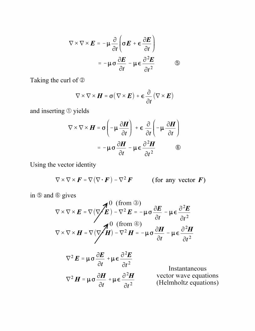
Taking the curl of ã
and inserting â yields
Using the vector identity
in æ and ç gives
For time-harmonic fields, the instantaneous (time-domain) vector F isrelated to the phasor (frequency-domain) vector Fs by
Using these relationships, the instantaneous vector wave equations aretransformed into the phasor vector wave equations:
If we let
the phasor vector wave equations reduce to
The complex constant ( is defined as the propagation constant.
The real part of the propagation constant (") is defined as the attenuationconstant while the imaginary part ($) is defined as the phase constant. Theattenuation constant defines the rate at which the fields of the wave areattenuated as the wave propagates. An electromagnetic wave propagatesin an ideal (lossless) media without attenuation ("= 0). The phase constantdefines the rate at which the phase changes as the wave propagates.
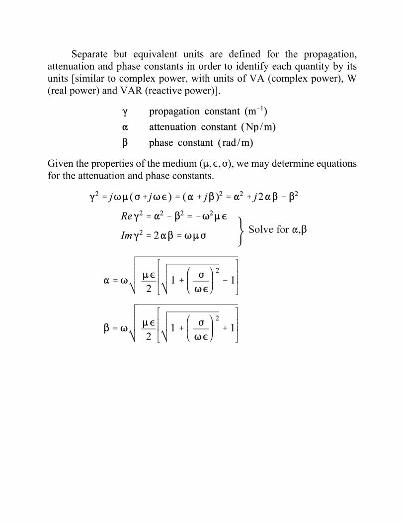
Separate but equivalent units are defined for the propagation,attenuation and phase constants in order to identify each quantity by itsunits [similar to complex power, with units of VA (complex power), W(real power) and VAR (reactive power)].
Given the properties of the medium (:,,,F), we may determine equationsfor the attenuation and phase constants.
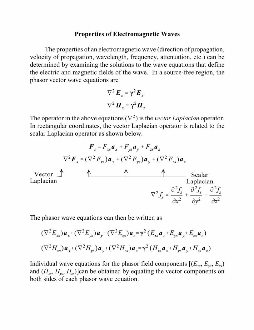
Properties of Electromagnetic Waves
The properties of an electromagnetic wave (direction of propagation,velocity of propagation, wavelength, frequency, attenuation, etc.) can bedetermined by examining the solutions to the wave equations that definethe electric and magnetic fields of the wave. In a source-free region, thephasor vector wave equations are
The operator in the above equations (L 2) is the vector Laplacian operator.In rectangular coordinates, the vector Laplacian operator is related to thescalar Laplacian operator as shown below.
The phasor wave equations can then be written as
Individual wave equations for the phasor field components [(Exs, Eys, Ezs)and (Hxs, Hys, Hzs)]can be obtained by equating the vector components onboth sides of each phasor wave equation.
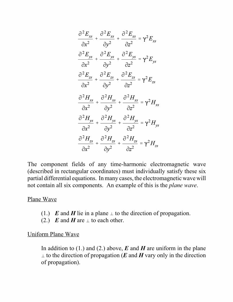
The component fields of any time-harmonic electromagnetic wave(described in rectangular coordinates) must individually satisfy these sixpartial differential equations. In many cases, the electromagnetic wave willnot contain all six components. An example of this is the plane wave.
Plane Wave
(1.) E and H lie in a plane z to the direction of propagation.(2.) E and H are z to each other.
Uniform Plane Wave
In addition to (1.) and (2.) above, E and H are uniform in the planez to the direction of propagation (E and H vary only in the directionof propagation).
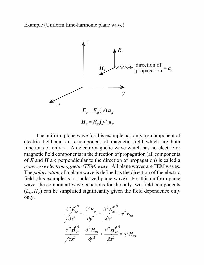
Example (Uniform time-harmonic plane wave)
The uniform plane wave for this example has only a z-component ofelectric field and an x-component of magnetic field which are bothfunctions of only y. An electromagnetic wave which has no electric ormagnetic field components in the direction of propagation (all componentsof E and H are perpendicular to the direction of propagation) is called atransverse electromagnetic (TEM) wave. All plane waves are TEM waves.The polarization of a plane wave is defined as the direction of the electricfield (this example is a z-polarized plane wave). For this uniform planewave, the component wave equations for the only two field components(Ezs, Hxs) can be simplified significantly given the field dependence on yonly.
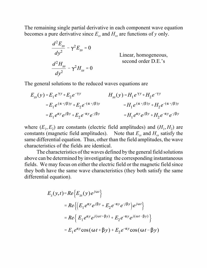
The remaining single partial derivative in each component wave equationbecomes a pure derivative since Ezs and Hxs are functions of y only.
The general solutions to the reduced waves equations are
where (E1, E2) are constants (electric field amplitudes) and (H1, H2) areconstants (magnetic field amplitudes). Note that Ezs and Hxs satisfy thesame differential equation. Thus, other than the field amplitudes, the wavecharacteristics of the fields are identical.
The characteristics of the waves defined by the general field solutionsabove can be determined by investigating the corresponding instantaneousfields. We may focus on either the electric field or the magnetic field sincethey both have the same wave characteristics (they both satisfy the samedifferential equation).
Linear, homogeneous,second order D.E.’s
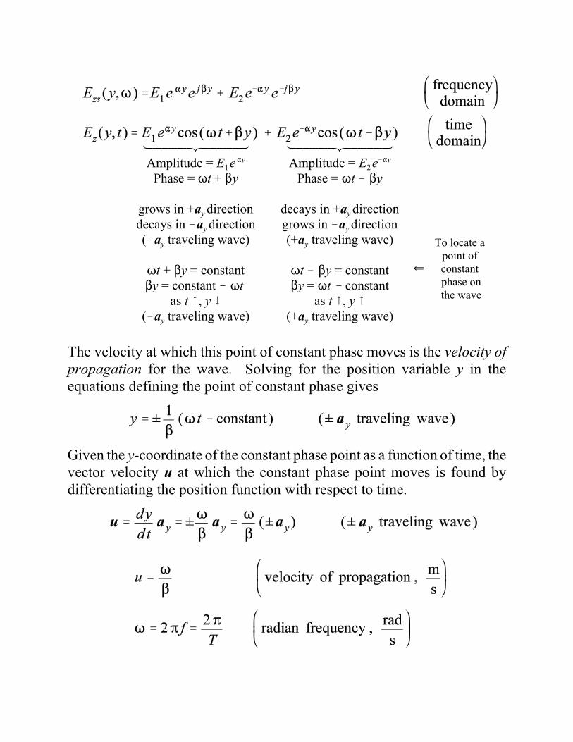
The velocity at which this point of constant phase moves is the velocity ofpropagation for the wave. Solving for the position variable y in theequations defining the point of constant phase gives
Given the y-coordinate of the constant phase point as a function of time, thevector velocity u at which the constant phase point moves is found bydifferentiating the position function with respect to time.
ÆÉÉÉÉÉÉÉÉÉÉÉÈÉÉÉÉÉÉÉÉÉÉÉÇAmplitude = E1 e"y
Phase = Tt + $y
grows in +ay directiondecays in !ay direction(!ay traveling wave)
Tt + $y = constant$y = constant ! Tt
as t 8, y 9(!ay traveling wave)
ÆÉÉÉÉÉÉÉÉÉÉÉÈÉÉÉÉÉÉÉÉÉÉÉÇAmplitude = E2 e!"y
Phase = Tt ! $y
decays in +ay directiongrows in !ay direction(+ay traveling wave)
Tt ! $y = constant$y = Tt ! constant
as t 8, y 8(+ay traveling wave)
To locate a point of constant phase onthe wave
Z

Given a wave traveling at a velocity u, the wave travels onewavelength (8) during one period (T ).
For a uniform plane wave propagating in a given medium, the ratioof electric field to magnetic field is a constant. The units on this ratio hasunits of ohms and is defined as the intrinisic wave impedance for themedium. Assuming a +ay traveling uniform plane wave defined by anelectric field of
the corresponding magnetic field is found from the source free Maxwell’sequations.
Note that the direction of propagation for this wave is in the same directionas E×H (az×ax = ay). This characteristic is true for all plane waves.
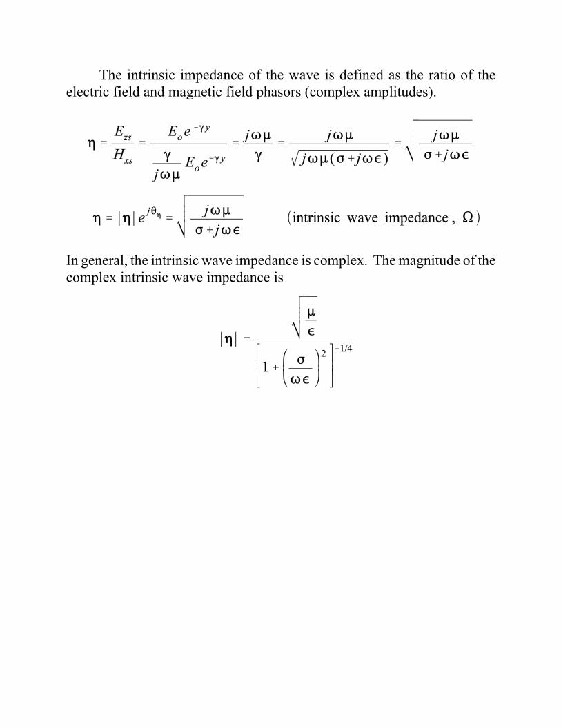
The intrinsic impedance of the wave is defined as the ratio of theelectric field and magnetic field phasors (complex amplitudes).
In general, the intrinsic wave impedance is complex. The magnitude of thecomplex intrinsic wave impedance is
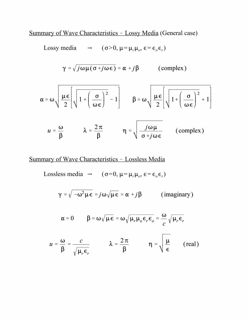
Summary of Wave Characteristics ! Lossy Media (General case)
Lossy media Y (F>0, := :r:o, ,= ,o,r)
Summary of Wave Characteristics ! Lossless Media
Lossless media Y (F=0, := :r:o, ,= ,o,r)
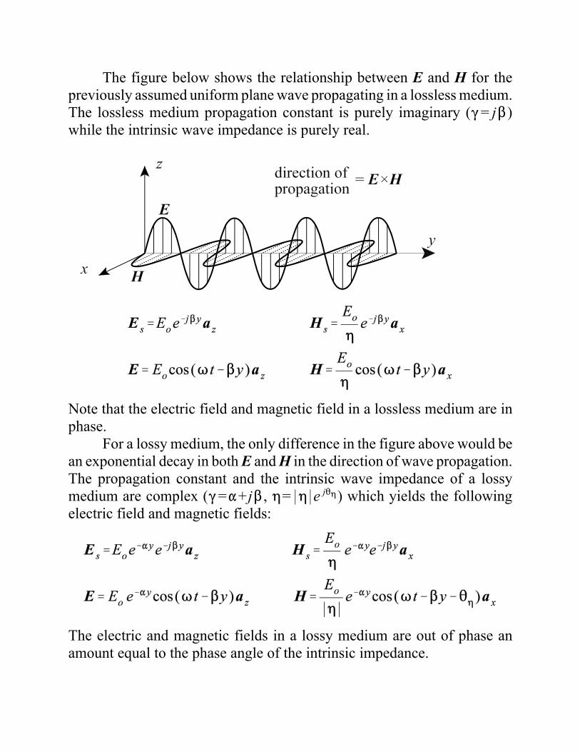
The figure below shows the relationship between E and H for thepreviously assumed uniform plane wave propagating in a lossless medium.The lossless medium propagation constant is purely imaginary ((= j$)while the intrinsic wave impedance is purely real.
Note that the electric field and magnetic field in a lossless medium are inphase.
For a lossy medium, the only difference in the figure above would bean exponential decay in both E and H in the direction of wave propagation.The propagation constant and the intrinsic wave impedance of a lossymedium are complex ((="+ j$ , 0=*0*e j20) which yields the followingelectric field and magnetic fields:
The electric and magnetic fields in a lossy medium are out of phase anamount equal to the phase angle of the intrinsic impedance.
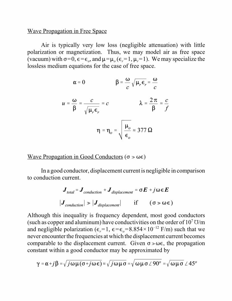
Wave Propagation in Free Space
Air is typically very low loss (negligible attenuation) with littlepolarization or magnetization. Thus, we may model air as free space(vacuum) with F=0, ,=,o, and :=:o (,r=1, :r=1). We may specialize thelossless medium equations for the case of free space.
Wave Propagation in Good Conductors (F oT,)
In a good conductor, displacement current is negligible in comparisonto conduction current.
Although this inequality is frequency dependent, most good conductors(such as copper and aluminum) have conductivities on the order of 107 É/mand negligible polarization (,r=1, ,=,o=8.854×10!12 F/m) such that wenever encounter the frequencies at which the displacement current becomescomparable to the displacement current. Given FoT,, the propagationconstant within a good conductor may be approximated by
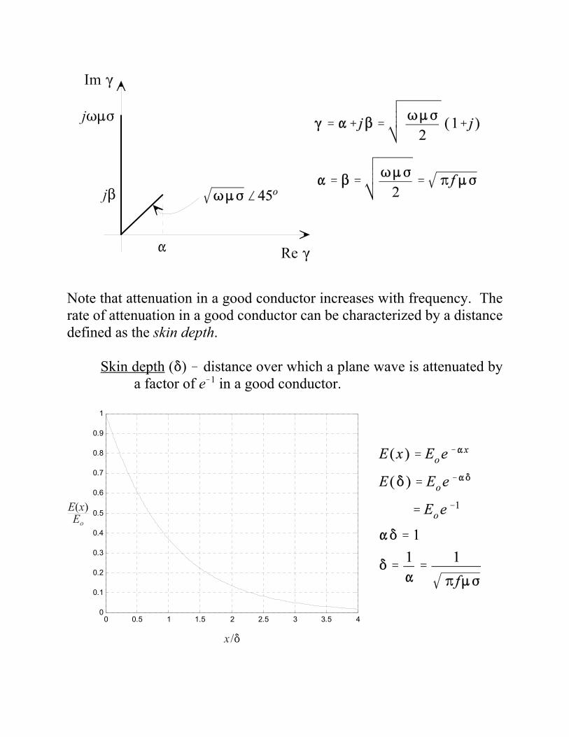
Note that attenuation in a good conductor increases with frequency. Therate of attenuation in a good conductor can be characterized by a distancedefined as the skin depth.
Skin depth (*) ! distance over which a plane wave is attenuated bya factor of e!1 in a good conductor.
0 0.5 1 1.5 2 2.5 3 3.5 40
0.1
0.2
0.3
0.4
0.5
0.6
0.7
0.8
0.9
1
The velocity of propagation, wavelength and intrinsic impedance within thegood conductor is
Example (skin depth)
Uniform plane wave ( f = 1 MHz) at an air/copper interface.
In the air,
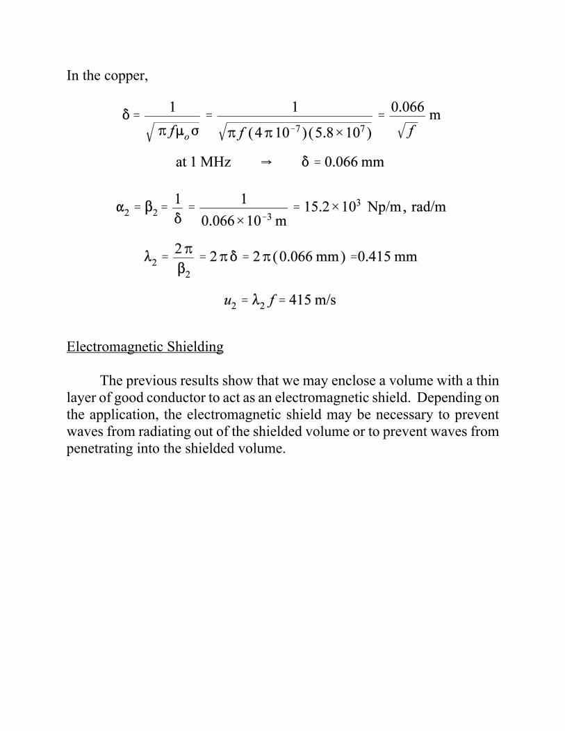
In the copper,
Electromagnetic Shielding
The previous results show that we may enclose a volume with a thinlayer of good conductor to act as an electromagnetic shield. Depending onthe application, the electromagnetic shield may be necessary to preventwaves from radiating out of the shielded volume or to prevent waves frompenetrating into the shielded volume.
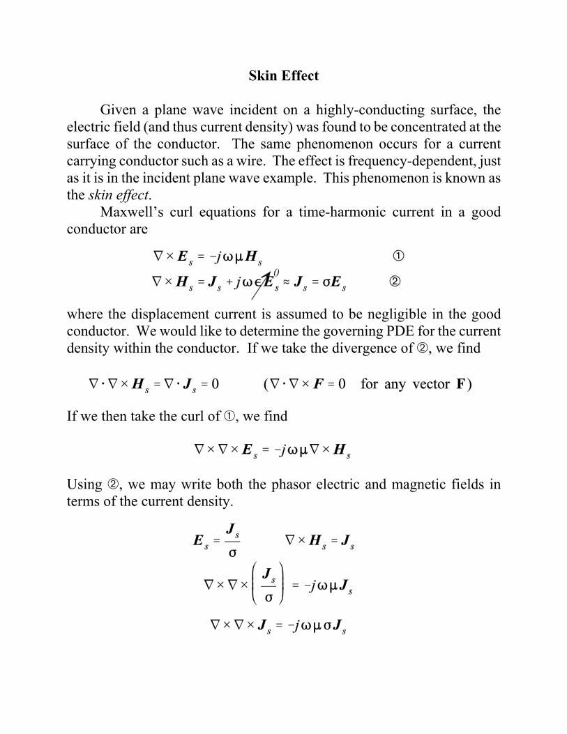
Skin Effect
Given a plane wave incident on a highly-conducting surface, theelectric field (and thus current density) was found to be concentrated at thesurface of the conductor. The same phenomenon occurs for a currentcarrying conductor such as a wire. The effect is frequency-dependent, justas it is in the incident plane wave example. This phenomenon is known asthe skin effect.
Maxwell’s curl equations for a time-harmonic current in a goodconductor are
where the displacement current is assumed to be negligible in the goodconductor. We would like to determine the governing PDE for the currentdensity within the conductor. If we take the divergence of ã, we find
If we then take the curl of â, we find
Using ã, we may write both the phasor electric and magnetic fields interms of the current density.
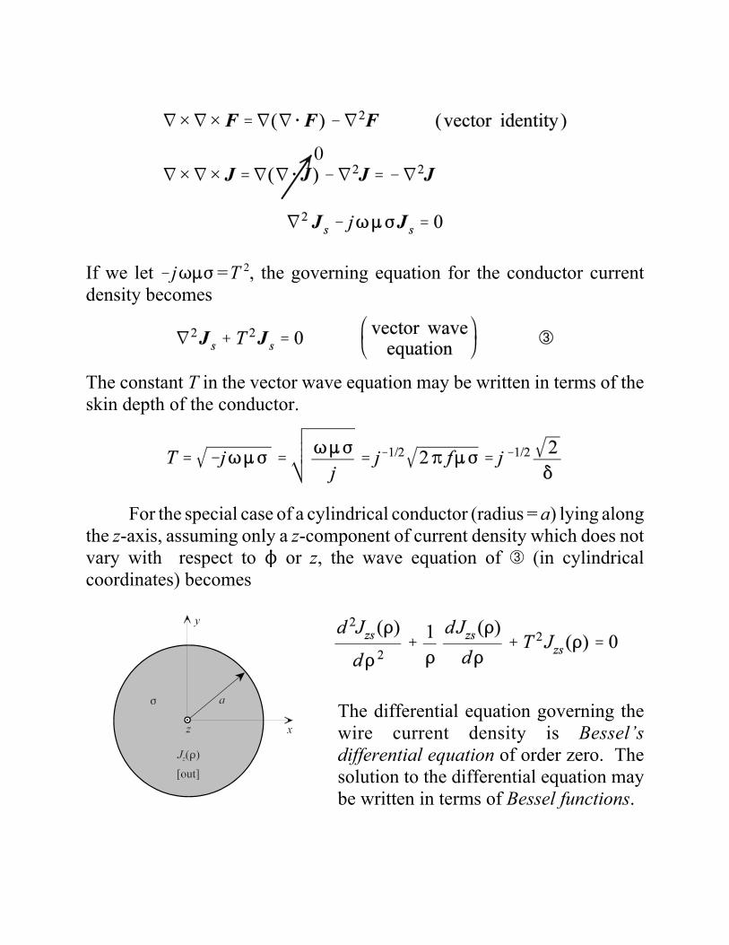
If we let !jT:F =T 2, the governing equation for the conductor currentdensity becomes
The constant T in the vector wave equation may be written in terms of theskin depth of the conductor.
For the special case of a cylindrical conductor (radius = a) lying alongthe z-axis, assuming only a z-component of current density which does notvary with respect to N or z, the wave equation of ä (in cylindricalcoordinates) becomes
The differential equation governing thewire current density is Bessel’sdifferential equation of order zero. Thesolution to the differential equation maybe written in terms of Bessel functions.
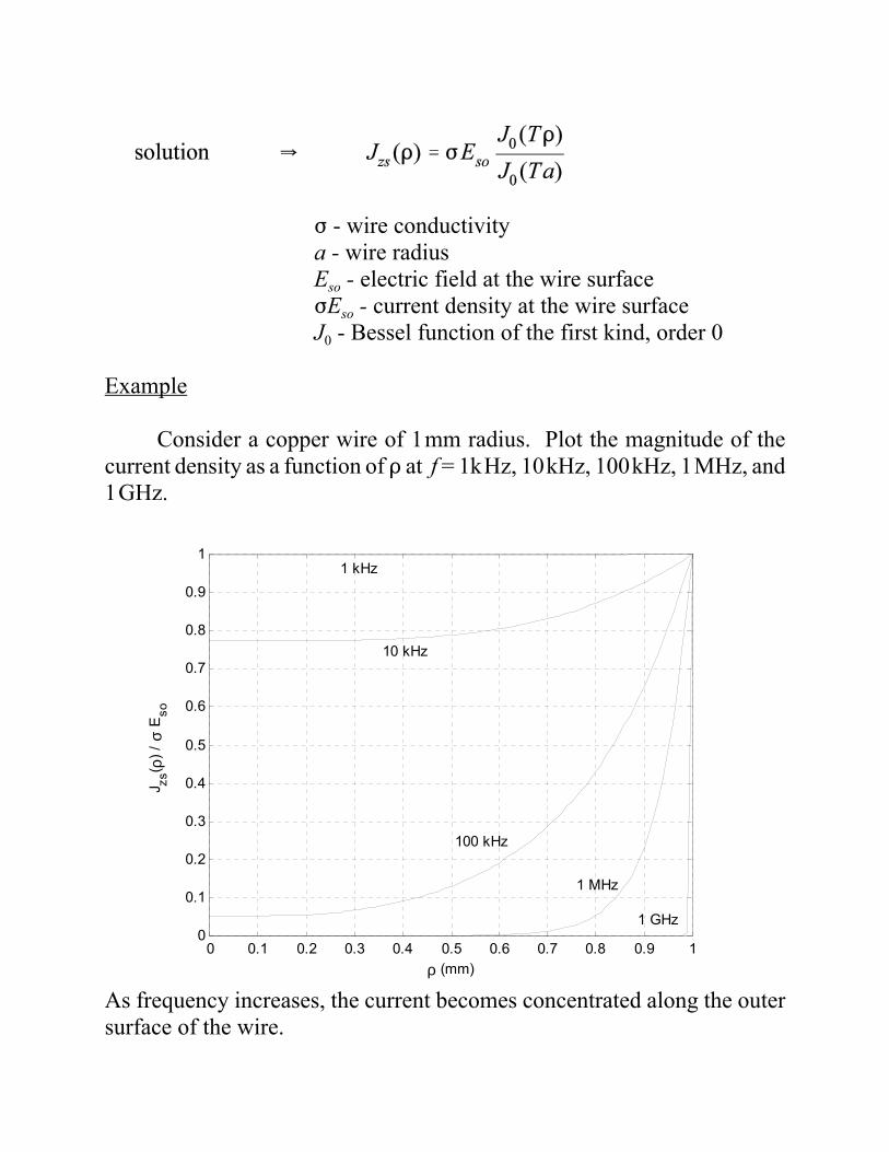
F - wire conductivitya - wire radiusEso - electric field at the wire surfaceFEso - current density at the wire surfaceJ0 - Bessel function of the first kind, order 0
Example
Consider a copper wire of 1mm radius. Plot the magnitude of thecurrent density as a function of D at f = 1kHz, 10kHz, 100kHz, 1MHz, and1GHz.
As frequency increases, the current becomes concentrated along the outersurface of the wire.
0 0.1 0.2 0.3 0.4 0.5 0.6 0.7 0.8 0.9 10
0.1
0.2
0.3
0.4
0.5
0.6
0.7
0.8
0.9
1
ρ (mm)
J zs( ρ
) / σ
Eso
1 kHz
10 kHz
100 kHz
1 MHz
1 GHz
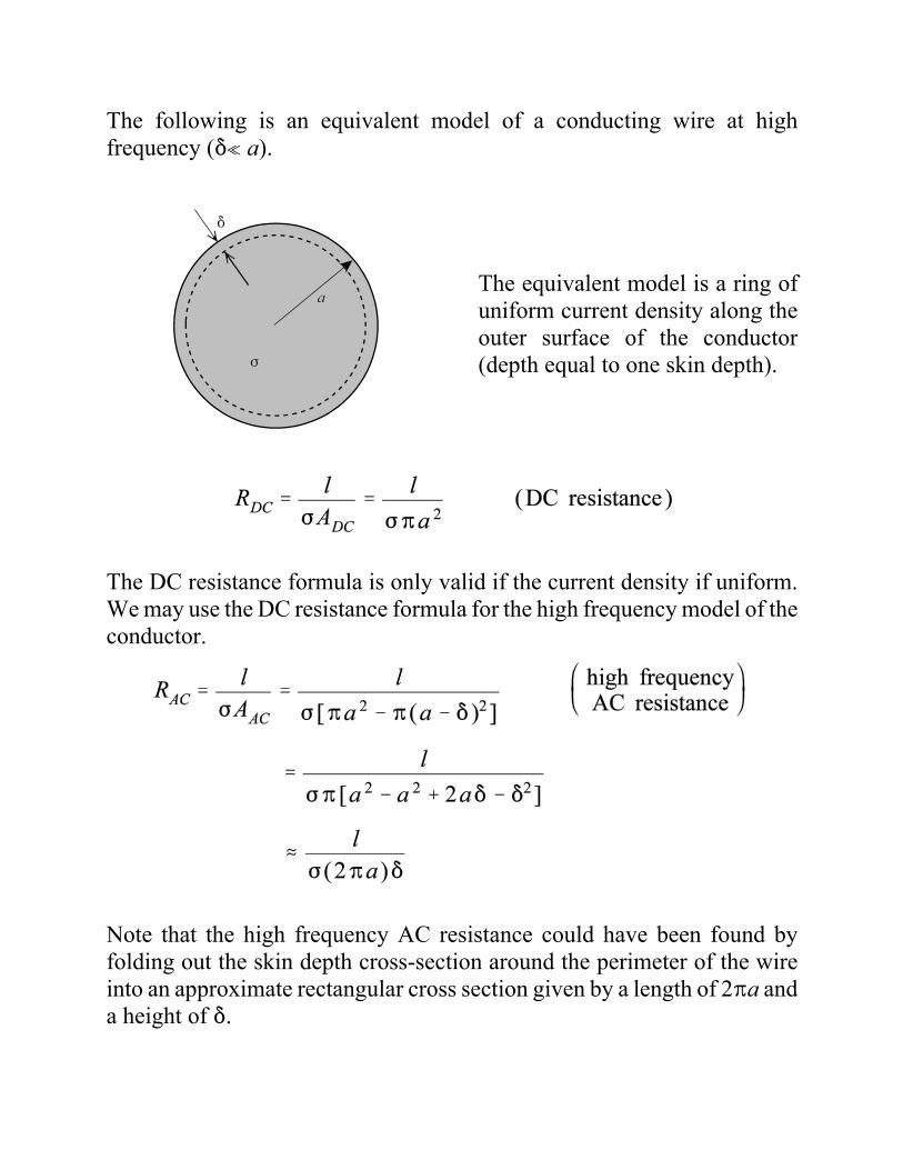
The following is an equivalent model of a conducting wire at highfrequency (*n a).
The equivalent model is a ring ofuniform current density along theouter surface of the conductor(depth equal to one skin depth).
The DC resistance formula is only valid if the current density if uniform.We may use the DC resistance formula for the high frequency model of theconductor.
Note that the high frequency AC resistance could have been found byfolding out the skin depth cross-section around the perimeter of the wireinto an approximate rectangular cross section given by a length of 2Ba anda height of *.
ÆÉÉÉÉÉÉÉÉÉÉÉÈÉÉÉÉÉÉÉÉÉÉÉÉÇdefine as complex
permittivity ,c
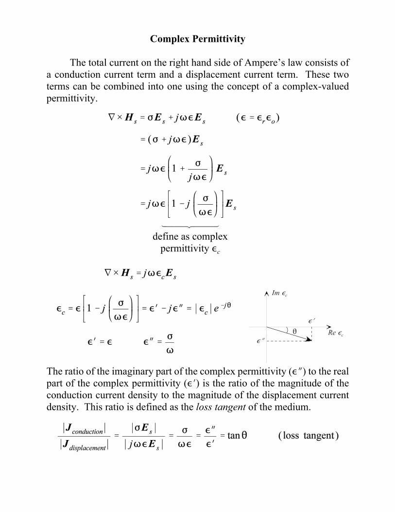
Complex Permittivity
The total current on the right hand side of Ampere’s law consists ofa conduction current term and a displacement current term. These twoterms can be combined into one using the concept of a complex-valuedpermittivity.
The ratio of the imaginary part of the complex permittivity (,O) to the realpart of the complex permittivity (,N) is the ratio of the magnitude of theconduction current density to the magnitude of the displacement currentdensity. This ratio is defined as the loss tangent of the medium.
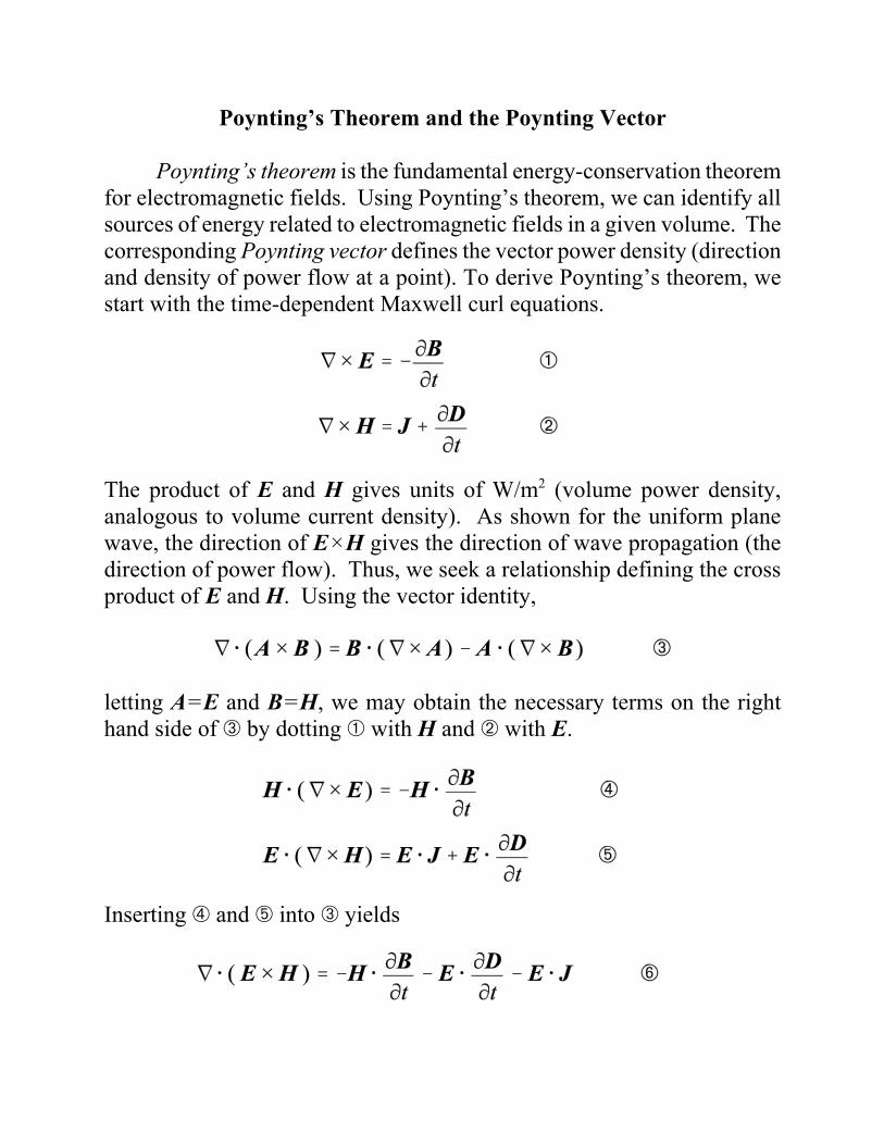
Poynting’s Theorem and the Poynting Vector
Poynting’s theorem is the fundamental energy-conservation theoremfor electromagnetic fields. Using Poynting’s theorem, we can identify allsources of energy related to electromagnetic fields in a given volume. Thecorresponding Poynting vector defines the vector power density (directionand density of power flow at a point). To derive Poynting’s theorem, westart with the time-dependent Maxwell curl equations.
The product of E and H gives units of W/m2 (volume power density,analogous to volume current density). As shown for the uniform planewave, the direction of E×H gives the direction of wave propagation (thedirection of power flow). Thus, we seek a relationship defining the crossproduct of E and H. Using the vector identity,
letting A=E and B=H, we may obtain the necessary terms on the righthand side of ä by dotting â with H and ã with E.
Inserting å and æ into ä yields
ÆÉÉÉÉÉÉÉÉÈÉÉÉÉÉÉÉÉÇnet power
flow out of V
ÆÉÉÉÉÉÉÉÉÉÉÉÉÉÉÉÉÉÉÉÉÉÉÈÉÉÉÉÉÉÉÉÉÉÉÉÉÉÉÉÉÉÉÉÉÉÇdecrease in the storedelectric and magnetic
energy within V
ÆÉÉÉÉÈÉÉÉÉÇohmiclosses
within V
The three terms on the right hand side of ç may be rewritten as
which gives
Integrating è over a given volume V (enclosed by a surface S) and applyingthe divergence theorem yields
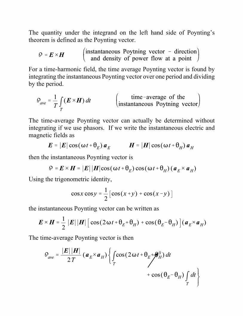
The quantity under the integrand on the left hand side of Poynting’stheorem is defined as the Poynting vector.
For a time-harmonic field, the time average Poynting vector is found byintegrating the instantaneous Poynting vector over one period and dividingby the period.
The time-average Poynting vector can actually be determined withoutintegrating if we use phasors. If we write the instantaneous electric andmagnetic fields as
then the instantaneous Poynting vector is
Using the trigonometric identity,
the instantaneous Poynting vector can be written as
The time-average Poynting vector is then
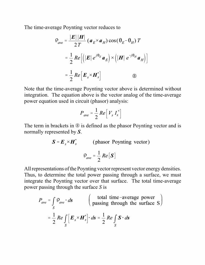
The time-average Poynting vector reduces to
Note that the time-average Poynting vector above is determined withoutintegration. The equation above is the vector analog of the time-averagepower equation used in circuit (phasor) analysis:
The term in brackets in é is defined as the phasor Poynting vector and isnormally represented by S.
All representations of the Poynting vector represent vector energy densities.Thus, to determine the total power passing through a surface, we mustintegrate the Poynting vector over that surface. The total time-averagepower passing through the surface S is
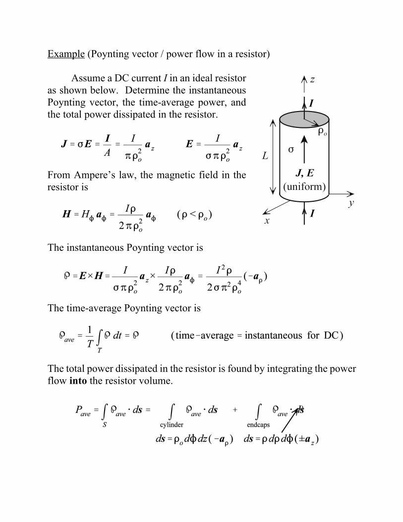
Example (Poynting vector / power flow in a resistor)
Assume a DC current I in an ideal resistoras shown below. Determine the instantaneousPoynting vector, the time-average power, andthe total power dissipated in the resistor.
From Ampere’s law, the magnetic field in theresistor is
The instantaneous Poynting vector is
The time-average Poynting vector is
The total power dissipated in the resistor is found by integrating the powerflow into the resistor volume.
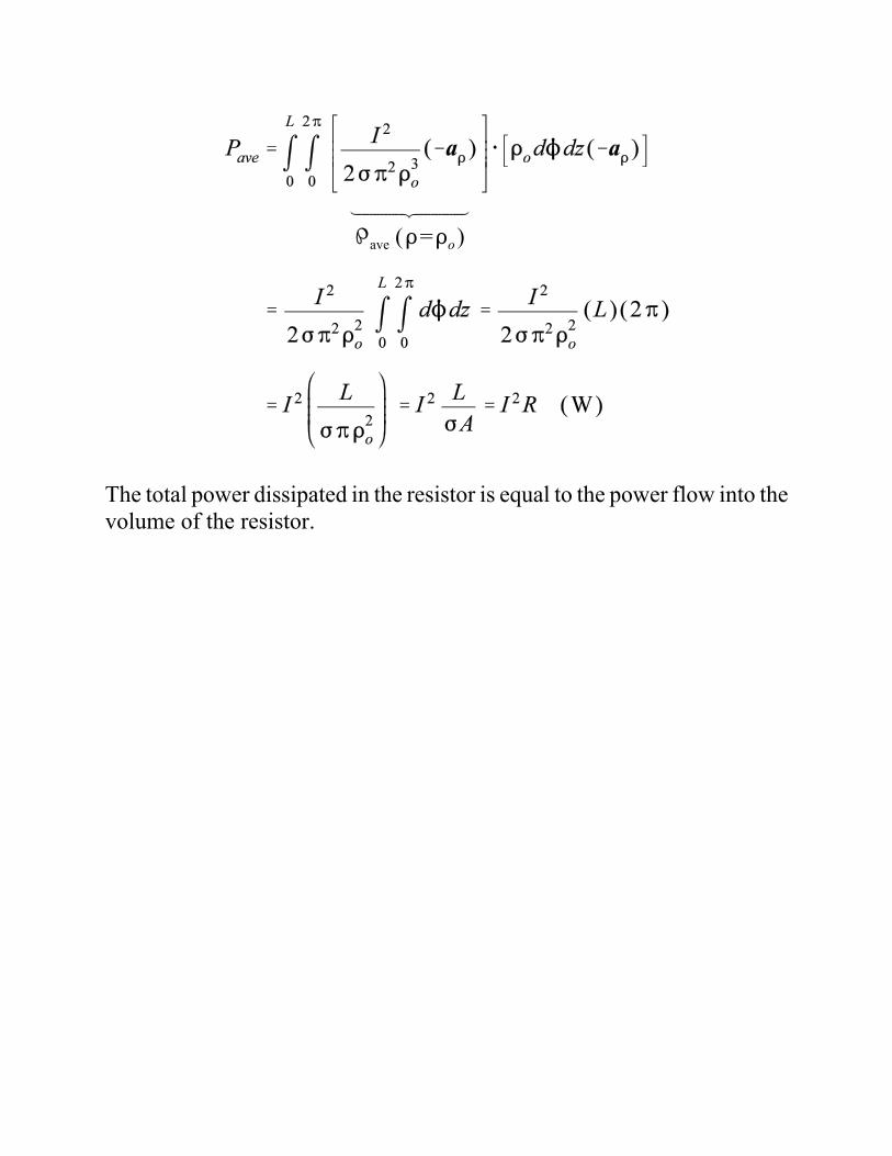
ÆÉÉÉÉÉÉÉÉÉÉÈÉÉÉÉÉÉÉÉÉÉÇave (D=Do)
The total power dissipated in the resistor is equal to the power flow into thevolume of the resistor.
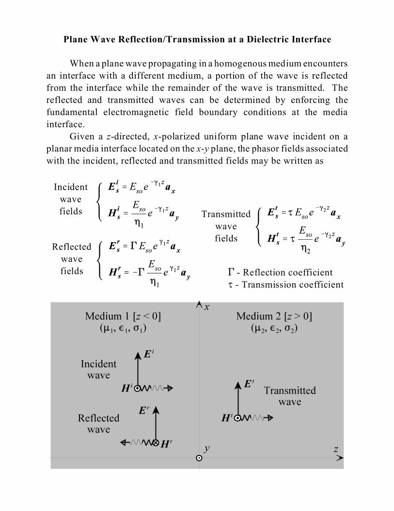
Plane Wave Reflection/Transmission at a Dielectric Interface
When a plane wave propagating in a homogenous medium encounters
an interface with a different medium, a portion of the wave is reflected
from the interface while the remainder of the wave is transmitted. The
reflected and transmitted waves can be determined by enforcing the
fundamental electromagnetic field boundary conditions at the media
interface.
Given a z-directed, x-polarized uniform plane wave incident on a
planar media interface located on the x-y plane, the phasor fields associated
with the incident, reflected and transmitted fields may be written as
9
Incident
wave
fields
9
9
Transmitted
wave
fieldsReflected
wave
fields ' - Reflection coefficient
J - Transmission coefficient
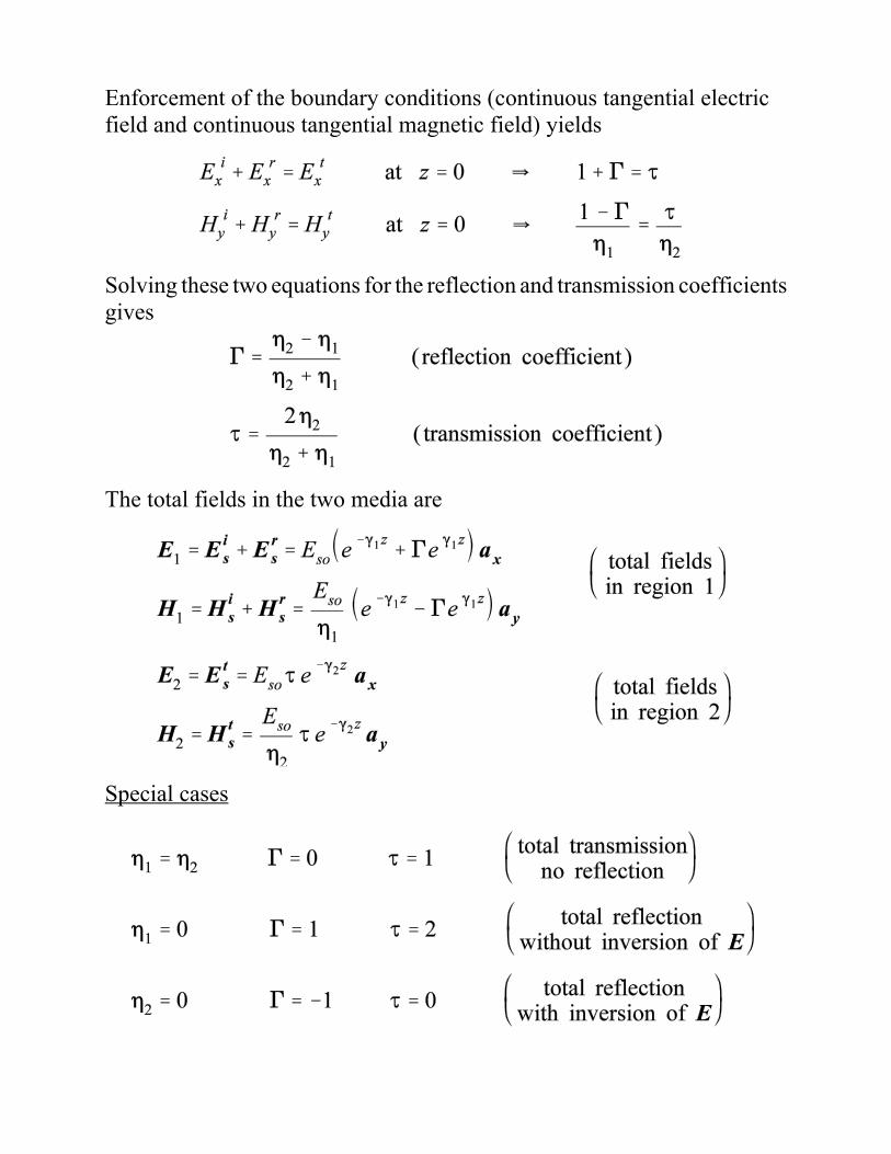
Enforcement of the boundary conditions (continuous tangential electricfield and continuous tangential magnetic field) yields
Solving these two equations for the reflection and transmission coefficientsgives
The total fields in the two media are
Special cases
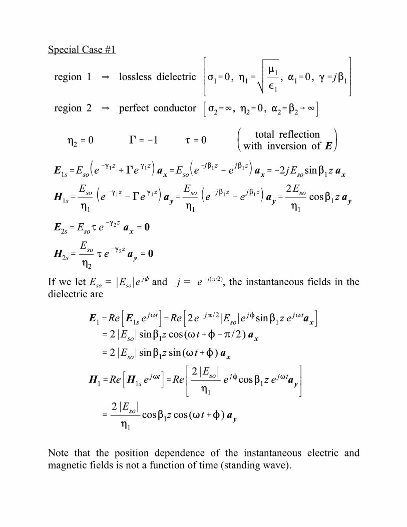
Special Case #1
If we let Eso = *Eso*e jN and !j = e! j(B/2), the instantaneous fields in thedielectric are
Note that the position dependence of the instantaneous electric andmagnetic fields is not a function of time (standing wave).
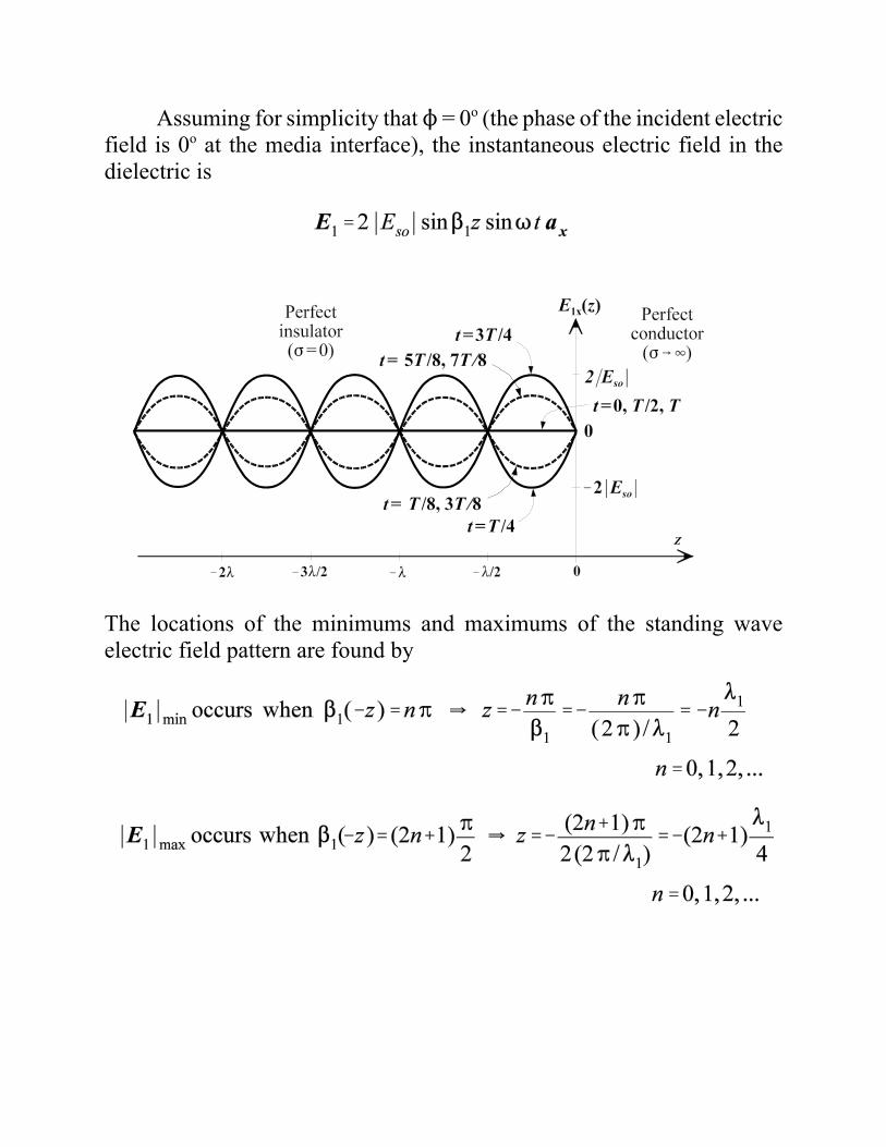
Assuming for simplicity that N = 0o (the phase of the incident electricfield is 0o at the media interface), the instantaneous electric field in thedielectric is
The locations of the minimums and maximums of the standing waveelectric field pattern are found by
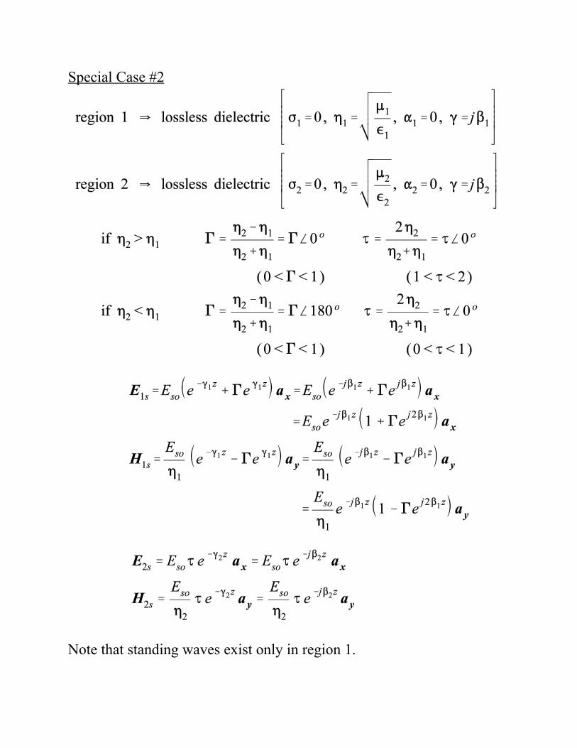
Special Case #2
Note that standing waves exist only in region 1.
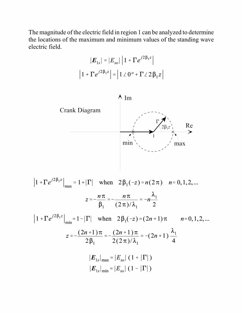
The magnitude of the electric field in region 1 can be analyzed to determinethe locations of the maximum and minimum values of the standing waveelectric field.
If 02 > 01 ( ' is positive), then
If 01 > 02 ( ' is negative), and the positions of the maximums andminimums are reversed, but the equations for the maximum and minimumelectric field magnitudes in terms of *'* are the same.
The standing wave ratio (s) in a region where standing waves existis defined as the ratio of the maximum electric field magnitude to theminimum electric field magnitude.
The standing wave ratio (purely real) ranges from a minimum value of 1(no reflection, *'*=0) to 4 (total reflection, *'*=1). The standing waveratio is sometimes defined is dB as
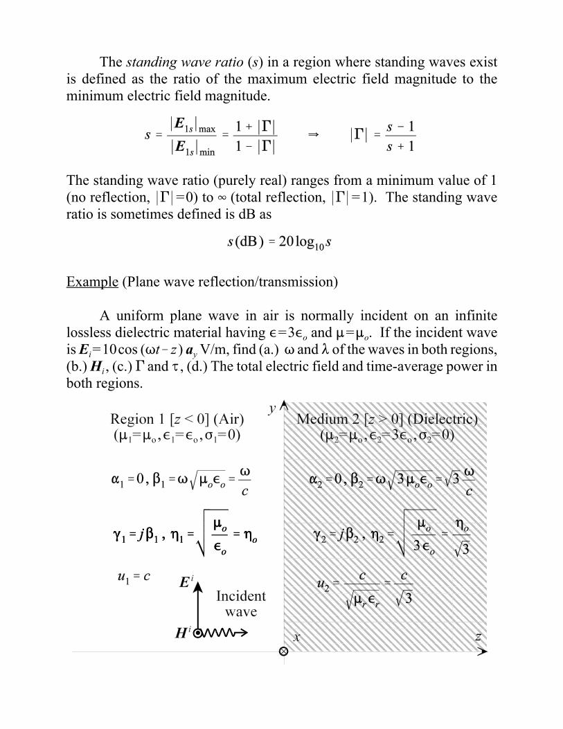
Example (Plane wave reflection/transmission)
A uniform plane wave in air is normally incident on an infinitelossless dielectric material having ,=3,o and :=:o. If the incident waveis Ei=10cos (Tt!z) ay V/m, find (a.) T and 8 of the waves in both regions,(b.) Hi , (c.) ' and J , (d.) The total electric field and time-average power inboth regions.
(a.)
(b.)
(c.)
(d.)

In general, the power flow for a plane wave may be written as
For a plane wave propagating in a lossless dielectric (0 is real, 20= 0), thepower flow reduces to
For this problem,
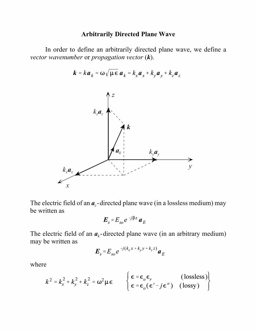
Arbitrarily Directed Plane Wave
In order to define an arbitrarily directed plane wave, we define avector wavenumber or propagation vector (k).
The electric field of an az-directed plane wave (in a lossless medium) maybe written as
The electric field of an ak-directed plane wave (in an arbitrary medium)may be written as
where
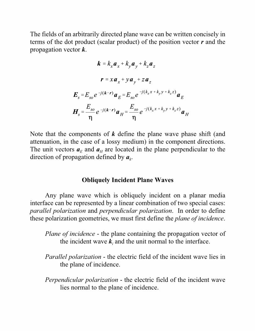
The fields of an arbitrarily directed plane wave can be written concisely interms of the dot product (scalar product) of the position vector r and thepropagation vector k.
Note that the components of k define the plane wave phase shift (andattenuation, in the case of a lossy medium) in the component directions.The unit vectors aE and aH are located in the plane perpendicular to thedirection of propagation defined by ak.
Obliquely Incident Plane Waves
Any plane wave which is obliquely incident on a planar mediainterface can be represented by a linear combination of two special cases:parallel polarization and perpendicular polarization. In order to definethese polarization geometries, we must first define the plane of incidence.
Plane of incidence - the plane containing the propagation vector ofthe incident wave ki and the unit normal to the interface.
Parallel polarization - the electric field of the incident wave lies inthe plane of incidence.
Perpendicular polarization - the electric field of the incident wavelies normal to the plane of incidence.

Parallel Polarization
For the media interface shown below, the plane of incidencecontaining the propagation vector and the normal to the interface is the x-zplane. The electric field of the incident wave also lies in the plane ofincidence such that this wave orientation is defined as parallel polarization.
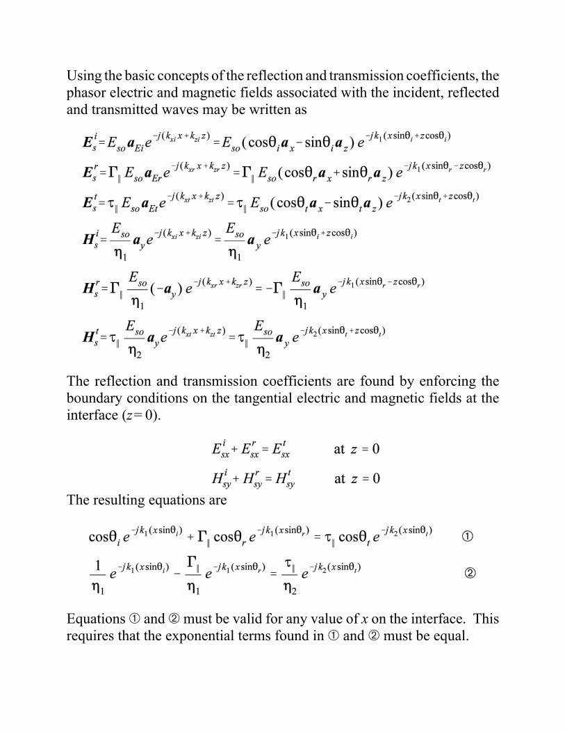
Using the basic concepts of the reflection and transmission coefficients, thephasor electric and magnetic fields associated with the incident, reflectedand transmitted waves may be written as
The reflection and transmission coefficients are found by enforcing theboundary conditions on the tangential electric and magnetic fields at theinterface (z=0).
The resulting equations are
Equations â and ã must be valid for any value of x on the interface. Thisrequires that the exponential terms found in â and ã must be equal.
Equating the complex exponential terms found in â and ã yields
or
where n1 and n2 are the refractive indices of the two media. The refractiveindices may be written as
If the media properties and angle of incidence are known, we may useSnell’s law to determine the angle of transmission 2t. Given that all of thecomplex exponential terms in â and ã are equal, these equations reduceto
Solving ä and å for '2 and J2 yields
Equations æ and ç are commonly referred to as the Fresnel equations forparallel polarization. These equations reduce to the normal incidenceequations when 2i=0.
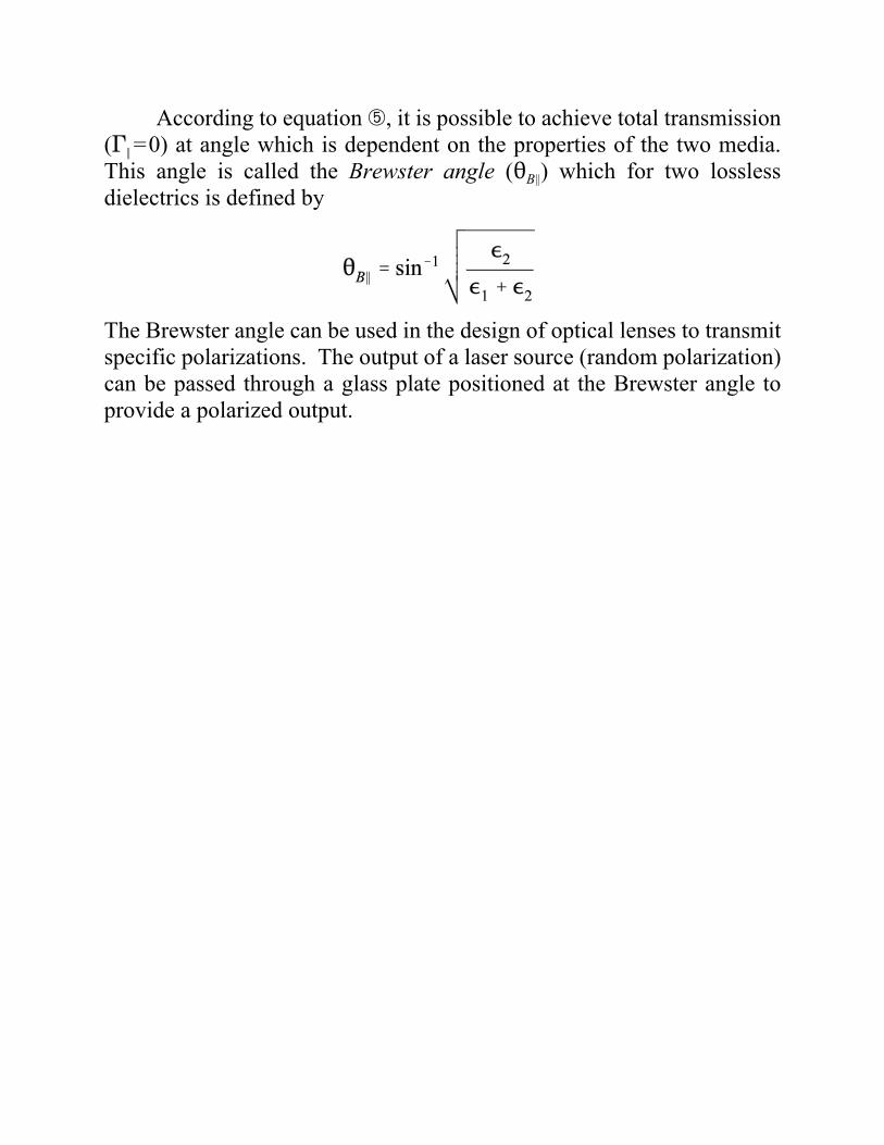
According to equation æ, it is possible to achieve total transmission('2=0) at angle which is dependent on the properties of the two media.This angle is called the Brewster angle (2B2) which for two losslessdielectrics is defined by
The Brewster angle can be used in the design of optical lenses to transmitspecific polarizations. The output of a laser source (random polarization)can be passed through a glass plate positioned at the Brewster angle toprovide a polarized output.
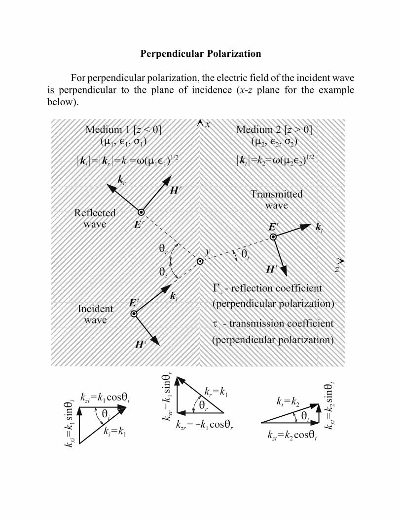
Perpendicular Polarization
For perpendicular polarization, the electric field of the incident waveis perpendicular to the plane of incidence (x-z plane for the examplebelow).
The electric and magnetic fields of the incident, reflected andtransmitted waves in the case of perpendicular polarization are
Enforcement of the boundary conditions and solving for the reflection andtransmission coefficients yields the Fresnel equations for perpendicularpolarization.


![Rudi Cilibrasi CWI CWI and University of Amsterdam · 2008-02-01 · arXiv:cs/0312044v2 [cs.CV] 9 Apr 2004 Clustering by Compression Rudi Cilibrasi∗ CWI Paul Vitanyi† CWI and](https://img.dokumen.tips/doc/110x75/5e70e6e6eee2db04ee355a74/rudi-cilibrasi-cwi-cwi-and-university-of-amsterdam-2008-02-01-arxivcs0312044v2.jpg)