Embed Size (px)
Citation preview

ELECTROMAGNETIC
THEORY
For ELECTRICAL ENGINEERING
ELECTRONICS & COMMUNICATION ENGINEERING


SYLLABUS Elements of vector calculus: divergence and curl; Gauss’ and Stokes’ theorems, Maxwell’s equations: differential and integral forms. Wave equation, Poynting vector. Plane waves: propagation through various media; reflection and refraction; phase and group velocity; skin depth. Transmission lines: characteristic impedance; impedance transformation; Smith chart; impedance matching; S parameters, pulse excitation. Waveguides: modes in rectangular waveguides; boundary conditions; cut-off frequencies; dispersion relations. Basics of propagation in dielectric waveguide and optical fibers. Basics of Antennas: Dipole antennas; radiation pattern; antenna gain.
ANALYSIS OF GATE PAPERS
Exam Year 1 Mark Ques. 2 Mark Ques. Total 2003 2 7 16 2004 2 6 14 2005 2 6 14 2006 2 8 18 2007 2 7 16 2008 2 5 12 2009 2 3 8 2010 3 2 7 2011 4 3 10 2012 4 5 14 2013 1 2 5
2014 Set-1 2 3 8 2014 Set-2 2 4 10 2014 Set-3 2 3 8 2014 Set-4 4 3 10 2015 Set-1 2 4 10 2015 Set-2 2 3 8 2015 Set-3 2 4 10 2016 Set-1 2 4 10 2016 Set-2 3 4 11 2016 Set-3 2 4 10 2017 Set-1 1 3 7 2017 Set-2 2 3 8
2018 2 3 8
ELECTROMAGNETIC THEORY
© Copyright Reserved by Gateflix.in No part of this material should be copied or reproduced without permission

Topics Page No
1. VECTORS & COORDINATE SYSTEMS
1.1 Vectors 01 1.2 Coordinate Systems and Transformation 02 1.3 Differential Length, Area, & Volume 03 1.4 Del Operator 03 1.5 Classification of Vector Fields 05
2. ELECTROSTATICS
2.1 Coulomb's Law 06 2.2 Electric Field Intensity 06 2.3 Gauss’s Law – Maxwell’s Equation 08 2.4 Electric Potential 09 2.5 Electric Dipole 09 2.6 Energy Density in Electrostatic Fields 10 2.7 Continuity Equation 11 2.8 Boundary Conditions 11 2.9 Poisson’s And Laplace’s Equations 11 2.10 Capacitances 11 2.11 Method of Images 12
3. MAGNETOSTATICS
3.1 Introduction 14 3.2 Biot – Savart’s Law 15 3.3 Magnetic Filed Intensity 15 3.4 Ampere’s Circuit Law – Maxwell’s Equation 16 3.5 Magnetic Flux Density – Maxwell’s Equation 18 3.6 Force Due To Magnetic Filed 18 3.7 Magnetic Torque and Moment 19 3.8 Magnetic Boundary Conditions 19 3.9 Inductor and Inductances 19 3.10 Magnetic Energy 19
Gate Questions 21
4. MAXWELL’S EQUATIONS
4.1 Faraday’s Law 36 4.2 Displacement Current 36 4.3 Time – Varying Potentials 37
CONTENTS
© Copyright Reserved by Gateflix.in No part of this material should be copied or reproduced without permission
4.4 Time – Harmonic Field 37
5. UNIFORM PLANE WAVES
5.1 Uniform Plane Waves 39 5.2 The Poynting Vector 41 5.3 Reflection of Plane Wave 41
Gate Questions 44
6. TRANSMISSION LINES
6.1 Introduction 58 6.2 Transmission Line Equations 58 6.3 Input Impedance, SWR, and Power 60 6.4 Applications of Transmission Lines 61
Gate Questions 63
7. WAVEGUIDES
7.1 Parallel Plane Waveguides 76 7.2 Wave Behavior Between Guides 76 7.3 Cut-Off Frequency 77 7.4 Phase Velocity & Guide Wavelength 77 7.5 Wave Angle 78 7.6 Modes of Operation 78 7.7 Rectangular Waveguides 79 7.8 TE Waves in Rectangular Waveguides 80 7.9 Dominate Mode of TE Waves 80 7.10 TM Waves in Rectangular Waveguides 80 7.11 Dominate Mode of TE Waves 80 7.12 Numerical Aperture 80 7.13 Attenuation 81 7.14 Dispersion 82
Gate Questions 83
8. ANTENNAS
8.1 Radiated Power of a Hertzian Dipole 92 8.2 Radiation of Half-Wave Dipole 92 8.3 Basic Terms and Definitions In Antennas 93 8.4 Study of Various Antenna 94
Gate Questions 96
9. ASSIGNMENT QUESTIONS 104
© Copyright Reserved by Gateflix.in No part of this material should be copied or reproduced without permission

1.1 VECTORS
A vector 𝐴𝐴 has both magnitude and direction. The magnitude of 𝐴𝐴 is a scalar written as A or |A|. A unit vector aA along 𝐴𝐴 is defined as a vector whose magnitude is unity and its direction is along A, that is,
AAa
| A |= x x y y z z
A 2 2 2x y z
ˆ ˆ ˆA a A a A aa
A A A
+ +=
+ +
A
B
C A
B
C
1.1.1 VECTOR ADDITION & SUBTRACTION
Two vectors 𝐴𝐴 and 𝐵𝐵 can be added together to give another vector𝐶𝐶; that is, 𝐶𝐶=𝐴𝐴+𝐵𝐵
Law Addition Multiplication Commutative 𝐴𝐴 + 𝐵𝐵 = 𝐵𝐵 + 𝐴𝐴 k𝐴𝐴 = 𝐴𝐴kAssociative 𝐴𝐴 + (𝐵𝐵 + 𝐶𝐶) k( A) (k )A=
= (𝐴𝐴 + 𝐵𝐵) +𝐶𝐶 Distributive k(𝐴𝐴+𝐵𝐵)=k𝐴𝐴+
k𝐵𝐵 The position vector rp (or radius vector) of point P is as the directed from the origin O to P; i.e., RP = 𝑂𝑂𝑂𝑂 = X𝑎𝑎x + Y𝑎𝑎y + Z𝑎𝑎z The distance vector is the displacement from one point to another.
PQ Q Pr r r= − Q P x Q P y Q P zˆ ˆ ˆ(x x )a (y y )a (z z )a= − + − + −
1.1.2 VECTOR MULTIPLICATION
• Scalar (or dot) product: 𝑨𝑨 . 𝑩𝑩• Vector (or cross) product: 𝑨𝑨× 𝑩𝑩
• Scalar triple product: 𝑨𝑨 . (𝑩𝑩×𝑪𝑪)• Vector triple product: 𝑨𝑨 × (𝑩𝑩 × 𝑪𝑪)
1. Dot ProductThe dot product of two vector 𝑨𝑨 and𝑩𝑩written as𝑨𝑨. 𝑩𝑩, is defined geometricallyas the product of the magnitudes of Aand B and the cosine of the anglebetween them.𝑨𝑨 . 𝑩𝑩 = AB cos ABθ
𝑨𝑨 . 𝑩𝑩 = AxBx + AyBy + AzBz
2. Cross Productx y z
AB n x y z
x y z
ˆ ˆ ˆa a aˆA B ABsin a , A B A A A
B B B× = θ × =
Note that the cross product has the following basic properties: i) It is not commutative:
A B B A× ≠ ×It is anti-commutative:A B B A× = − ×
ii) It is not associative:A (B C) (A B) C× × ≠ × ×
iii) It is distributive:A (B C) A B A C× + = × + ×
3. Scalar Triple ProductGiven three vectors 𝑨𝑨, 𝑩𝑩, and 𝑪𝑪, wedefine the scalar triple product asA.(B C) B.(C A) C.(A B)× = × = ×
x y z
x y z
x y z
A A AA.(B C) B B B
C C C× =
4. Vector Triple Product.A (B C) B(C . A) C(A . B)× × = −
1.1.3 COMPONENTS OF A VECTOR
1 VECTORS & CO-ORDINATE SYSTEMS
© Copyright Reserved by Gateflix.in No part of this material should be copied or reproduced without permission

The vector component AB of A along B is simply the scalar component
BA.BA A cosB
= θ =
1.2 COORDINATE SYSTEMS AND TRANSFORMATION
An orthogonal system is one in which the coordinates are mutually perpendicular.
1.2.1 CARTESIAN COORDINATES (X, Y, Z)
A point P can be represented as (x, y, z) as in Figure
The ranges of the coordinate variable x, y, and z are
x x=distance from yz planey y=distance from xz planez z=distance from xy plane
−∞ < < ∞−∞ < < ∞−∞ < < ∞
A vector A in Cartesian (otherwise known as rectangular) coordinates can be written as (Ax, Ay, Az) or 𝐴𝐴= Ax𝑎𝑎x + Ay𝑎𝑎y + Az𝑎𝑎z Where, ax, ay, and az are unit vectors along the x, y and z directions respectively,as shown in Figure.
1.2.2 CYLINDRICAL COORDINATES ( , , z)ρ ϕ
Azimuthal angle, is measured from the positive x-axis in the xy-plane; and z is the same as in the Cartesian system. ρ =radius ϕ =azimuthal angle z =height
xy
z
p aφ
ρa
ρaz
φ
The ranges of the variables are 00 2
z
≤ ρ < ∞≤ ϕ < π
−∞ < < ∞A vector 𝐴𝐴 in cylindrical coordinates can be written as
x
y
z
x
z
φρ
y = sin ρ φ
x = cos ρ φ
P(x, y, z) = P( , z)ρ, φ
z z zˆ ˆ ˆ(A ,A ,A ) or A a A a A aρ ϕ ρ ρ ϕ ϕ+ +
2 2 1 yx y , tan , z zx
−ρ = + ϕ = = orx cos , y sin , z z= ρ ϕ = ρ ϕ =
x
y
z z
A cos sin 0 AA sin cos 0 AA 0 0 1 A
ρ
ϕ
ϕ ϕ = − ϕ ϕ
or
x
y
z z
A cos sin 0 AA sin cos 0 AA 0 0 1 A
ρ
ϕ
ϕ − ϕ = ϕ ϕ
1.2.3 SPHERICAL COORDINATES (r, , )θ ϕ
R=radius θ =elevation angle ϕ =azimuthal angle
x
y
z
ax
ayaz
© Copyright Reserved by Gateflix.in No part of this material should be copied or reproduced without permission

aφ
φ
ar
aθ
θ
r
P
x
y
z
Range: 0 r , 0 & 0 2≤ < ∞ ≤ θ ≤ π ≤ ϕ < π
r, r rˆ ˆ ˆ(A A ,A ) or A a A a A aθ ϕ θ θ ϕ ϕ+ +2 2 2 1/2rA (A A A )θ ϕ= + +
2 22 2 2 1 x y
r x y z , tan ,z
− += + + θ =
1 ytanx
−ϕ = or x r sin cos , y r sin sin , z r cos= θ ϕ = θ ϕ = θ 1.2.4 CONSTANT-COORDINATE SURFACES
X = Constant Y = Constant Z = Constant ρ = Constant φ = Constant Z = Constant r = Constant θ= Constant
1.3 DIFFERENTIAL LENGTH, AREA, & VOLUME
A. Cartesian Coordinates 1) Differential displacement is given by
𝑑𝑑𝑑𝑑 = dx 𝑎𝑎x + dy 𝑎𝑎y + dz 𝑎𝑎z
2) Different normal area is given by𝑑𝑑𝑑𝑑 = dy dz 𝑎𝑎x or = dx dz 𝑎𝑎y or
= dz dy 𝑎𝑎z
3) Different volume is given byV = dx dy dz
B. Cylindrical Coordinates 1) Different displacement is given by
zˆ ˆ ˆdl d a d a dz aρ ϕ= ρ + ρ ϕ +
2) Different normal area is given byˆdS d dz aρ= ρ ϕ or
ˆd dz aϕ= ρ or
zˆd d a= ρ ϕ ρ3) Differential volume is given by
dV = d d dzρ ρ ϕ
C. Spherical Coordinates 1) The different displacement is
rˆ ˆ ˆdl dr a r d a r sin d aθ ϕ= + θ + θ ϕ
2) The differential normal area is2
rˆdS r sin d d a= θ θ ϕ orˆr sin dr d aθ= θ ϕ or
ˆr dr d aϕ= θ
3) The differential volume is2dV r sin dr d d= θ θ ϕ
The line integralL
A.dI∫ is the
integral of the tangential component of A along curve L. Given a vector field A, continuous in a region containing the smooth surface S, we define the surface Integral or the flux of A through S as
S
A.dSψ = ∫
1.4 DEL OPERATOR
x y zˆ ˆ ˆa a ax y z∂ ∂ ∂
∇ = + +∂ ∂ ∂
z1ˆ ˆ ˆa a a
zρ ϕ
∂ ∂ ∂∇ = + +
∂ρ ρ ∂ϕ ∂
r1 1ˆ ˆ ˆa a a
r r r sinθ ϕ
∂ ∂ ∂∇ = + +
∂ ∂θ θ ∂ϕ
1.4.1 APPLICATION OF DEL OPERATOR
• The gradient of a scalar V, written as ∇V
© Copyright Reserved by Gateflix.in No part of this material should be copied or reproduced without permission

• The divergence of a vector 𝐴𝐴, written as .A∇
• The curl of a vector A, written as ∇ × 𝐴𝐴 • The Laplacian of a scalar V, written
2V . V∇ = ∇ ∇ 1.4.2 GRADIENT OF A SCALAR
x y zV V Vˆ ˆ ˆV a a ax y z
∂ ∂ ∂∇ = + +
∂ ∂ ∂
zV 1 V Vˆ ˆ ˆV a a a
zρ ϕ
∂ ∂ ∂∇ = + +
∂ρ ρ ∂ϕ ∂
rV 1 V 1 Vˆ ˆ ˆV a a ar r r sinθ ϕ
∂ ∂ ∂∇ = + +
∂ ∂θ θ ∂ϕ
1.4.3 DIVERGENCE OF A VECTOR The divergence of 𝑨𝑨 at a given point P is the outward flux per unit volume as the volume shrinks about P.
S
v 0
A.dSdivA .A lim
v∆ →= ∇ =
∆
∫
yx zAA A.Ax y z
∂∂ ∂∇ = + +
∂ ∂ ∂ zA A1 1.A ( A )
zϕ
ρ
∂ ∂∂∇ = ρ + +
ρ ∂ρ ρ ∂ϕ ∂ 2
r2
1 1.A (r A ) (A sin )r r r sin θ
∂ ∂∇ = + θ
∂ θ ∂θ A1
r sinϕ∂
+θ ∂ϕ
1.4.4 GAUSS DIVERGENCE THEOREM The divergence theorem states that the total outward flux of a vector field 𝐴𝐴 through the closed surface S is the same as the volume integral of the divergence of 𝐴𝐴.
S v
A.dS .A dv= ∇∫ ∫
1.4.5 CURL OF A VECTOR The curl of 𝑨𝑨 is an axial (or rotational) vector whose magnitude is the maximum
circulation of 𝑨𝑨 per unit area as the area tends to zero and whose direction is the normal direction of the area when the area is oriented so as to make the circulation maximum. i. e.
Curl Lns 0 max
A.dIA A lim a
S∆ →
= ∇× = ∆
∫
x y z
x x y y z z
x y z
ˆ ˆ ˆa a a
ˆ ˆ ˆA ; A A a A a A ax y z
A A A
∂ ∂ ∂∇× = = + +
∂ ∂ ∂
z
z z
z
ˆ ˆ ˆa a a1 ˆ ˆ ˆA ; A A a A a A a
zA A A
ρ ϕ
ρ ρ ϕ ϕ
ρ ϕ
ρ∂ ∂ ∂
∇× = = + +ρ ∂ρ ∂ϕ ∂
ρ
r
r r2
r
ˆ ˆ ˆa r a r sin a1 ˆ ˆ ˆA ; A A a A a A a
r sin rA rA r sin A
θ ϕ
θ θ ϕ ϕ
θ ϕ
θ∂ ∂ ∂
∇× = = + +θ ∂ ∂θ ∂ϕ
θ
1.4.6 STOKES’S THEOREM Stokes’s theorem states that the circulation of a vector field A around a (closed) path L is equal to the surface integral of the curl of 𝐴𝐴 over the open surface S bounded by L provided that A and
A∇× are continuous on S.
L S
A.dI ( A).dS= ∇×∫ ∫
1.4.7 LAPLACIAN OF A SCALAR The Laplacian of a scalar field V, written as
2V . V∇ = ∇ ∇ , is the divergence of the gradient of V.
2 2 22
2 2 2
V V VVx y z
∂ ∂ ∂∇ = + +
∂ ∂ ∂
© Copyright Reserved by Gateflix.in No part of this material should be copied or reproduced without permission
2 22
2 2 2
1 V 1 V VVz
∂ ∂ ∂ ∂∇ = ρ + + ρ ∂ρ ∂ρ ρ ∂ϕ ∂
2 22 2
1 V 1 VV r sinr r r r sin
∂ ∂ ∂ ∂ ∇ = + θ ∂ ∂ θ ∂θ ∂θ
2
2 2 2
1 Vr sin
∂+
θ ∂ϕ
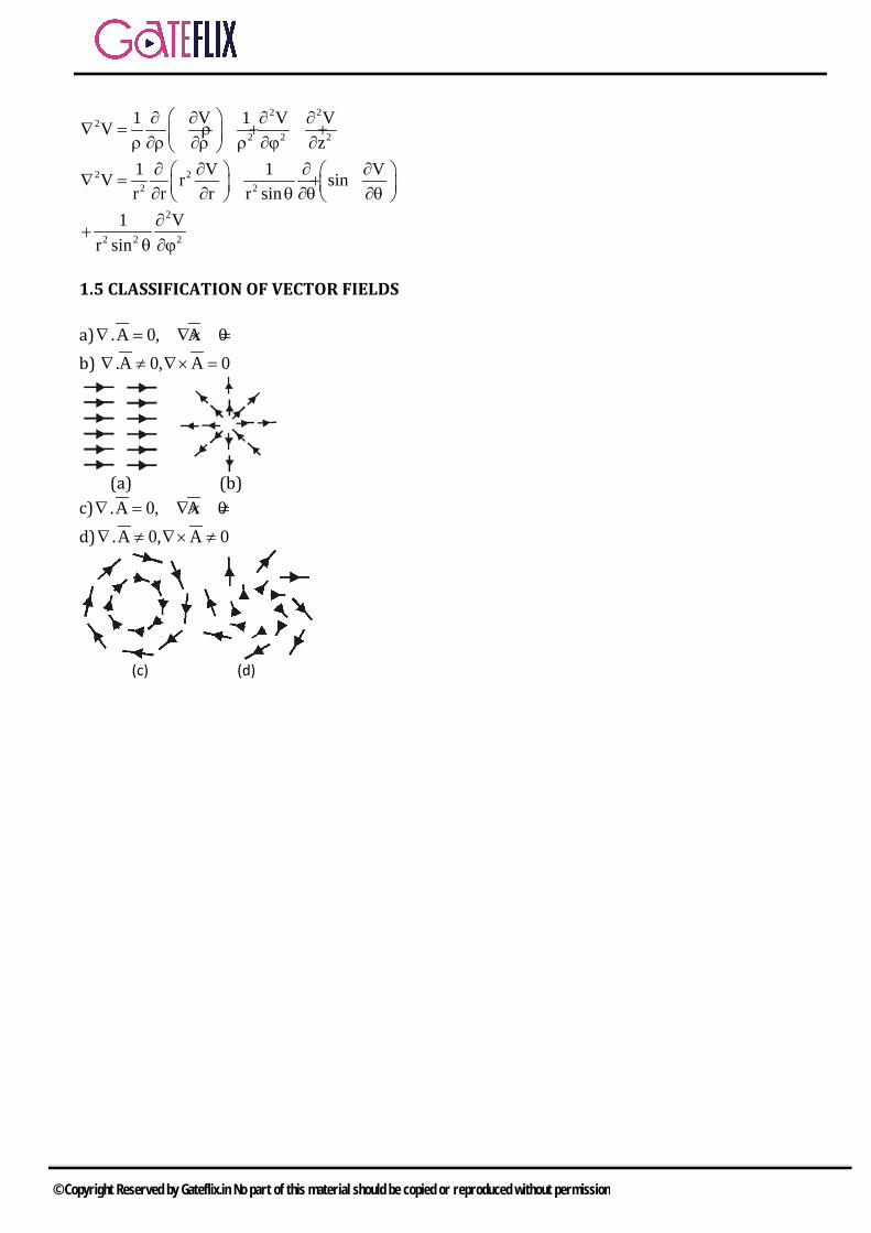
1.5 CLASSIFICATION OF VECTOR FIELDS a) .A 0, A 0∇ = ∇× = b) .A 0, A 0∇ ≠ ∇× =
(a) (b) c) .A 0, A 0∇ = ∇× ≠ d) .A 0, A 0∇ ≠ ∇× ≠
(c) (d)
© Copyright Reserved by Gateflix.in No part of this material should be copied or reproduced without permission

2.1 COULOMB'S LAW
It states that the force F between two point charges Q1 and Q2 is:
1. Along the line joining them2. Directly proportional to the product Q1,
Q2 of the charges3. Inversely proportional to the square of
the distance R between them.1 2
2
kQ QFR
=
912
0108.854 10 F / m36
−−ε = × ≈
πor
9
0
1k 9 10 m / F4
= ≈ ×πε
12
1 212 R2
0
Q Q ˆF a4 R
=πε
12 = 2 – 1
12
12R
RaR
=
21 = - 12
2.2 ELECTRIC FIELD INTENSITY
The electric field intensity ( or electric filed strength) E is the force per unit positive charge when placed in the electric field.
Q 0
FEQlim
→
= or Simply
FEQ
=
R 320 0
Q Q(r s ')ˆE a4 R 4 r r '
−= =
πε πε −
( )N kk
3k 10 k
Q r r1E4 r r=
−=
πε −∑
2.2.1 ELECTRIC FIELDS DUE TO CONTINOUS CHARGE DISTRIBUTIONS
1) Line charge:
dQ = ρL dl → Q = LL
dlρ∫L
R20L
dl ˆE a4 R
ρ=
πε∫Unit: Lρ :c/m
2) Surface charge:
S SS
dQ dS Q dS= ρ → = ρ∫s
R20s
dS ˆE a4 R
ρ=
πε∫Unit: sρ =c/m2
3) Volume charge:
v vdQ dv Q dv= ρ → = ρ∫v
R20V
dV ˆE a4 Rρ
=πε∫
Unit: volts/meter
2 ELECTROSTATICS
© Copyright Reserved by Gateflix.in No part of this material should be copied or reproduced without permission

2.2.2 ELECTRIC FIELD DUE TO A LINE CHARGE
dEzdE
dEρ
(x, y, z)
αα1
αα2
(0,0,z) T
B(0,0,z’)
dlA
0x
y
z
ρ
R
( )
( )zL
3/2220
a z z ' aE dz '
4 z z '
ρρ + −ρ=
πε ρ + − ∫
( )1/222R z z ' sec = ρ + − = ρ α
2z ' OT tan ,dz ' sec d= − ρ α = −ρ α α 2
1
2zL
2 20
ˆ ˆsec cos a sin a dE
4 sec
αρ
α
ρ α α + α α−ρ =πε ρ α∫
2
1
Lz
0
ˆ ˆcos a sin a d4
α
ρα
ρ = − α + α α πε ρ ∫
Thus for a finite line charge,
2 1φ ρ
h R
z
P(0,0,h) ρS
x
y
( ) ( )L2 1 2 1 z
0
ˆ ˆE sin sin a cos cos a4 ρ
ρ = − α − α + α − α πε ρ
As a special case, for an finite line charge, point B is at (0,0,∞) and A at (0,0,- ∞) so that α1 = π/2, α2 = -π/2; the z-component vanishes and eq. Becomes
L
0
ˆE a2 ρ
ρ=
πε ρ volts/meter
2.2.3 ELECTRIC FIELD DUE TO A SURFACE CHARGE
dv at(r’, ’, ’)θ φP(0,0,z)dEzdE
z
θ
φ’
r’
ρvα
x
y
R
SdQ dS= ρ
SS
Q dS= ρ∫
R20
dQ ˆdE a4 R
=πε
( ) zˆ ˆR a haρ= ρ − + 1/22 2R h = ρ +
RRaR
= s sdQ dS d d= ρ = ρ ρ ϕ ρ
s z3/22 2
0
ˆ ˆd d a hadE
4 hρ ρ ρ ϕ ρ −ρ + =
πε ρ +
2S
z z3/22 20 0 0
h d d ˆE dE a4 h
π ∞
ϕ= ρ=
ρ ρ ρ ϕ= =
πε ρ + ∫ ∫ ∫
( )3/22 2 2sz
0 0
h 1 ˆ2 h d a4 2
∞−ρ = π ρ + ρ πε ∫
1/22 2sz
00
h ˆh a2
∞−ρ = − ρ + ε
Sz
0
ˆE a2ρ
=ε
or Sn
0
ˆE a2ρ
=ε
For conducting charged plate
( )S S Sn n n
0 0 0
ˆ ˆ ˆE a a a2 2ρ −ρ ρ
= + − =ε ε ε
volts/meter
2.2.4 ELECTRIC FIELD DUE TO A VOLUME CHARGE
vdQ dv= ρ
© Copyright Reserved by Gateflix.in No part of this material should be copied or reproduced without permission
v vV V
Q dv dV= ρ = ρ∫ ∫
3
v4 a
3π
=ρ
vR2
0
dv ˆdE a4 R
ρ=
πε
2dv r sin dr d d= θ θ ϕ
vz z 2
0
dvcosˆE E.a dE cos4 Rρ α
= = α =πε∫ ∫
z20
Q ˆE a4 z
=πε
r20
Q ˆE a4 r
=πε
2.2.5 ELECTRIC FLUX DENSITY = ε0 : units:c/m2
S
D.dSΨ = ∫ (Total Flux)
L ˆD a2 ρ
ρ=
πρ (Line charge)
SnˆD a
2ρ
= (Sheet charge)
vR2
dv ˆD a (Volumecharge)4 Rρ
=π∫
2.3 GAUSS’S LAW – MAXEWELL’S EQUATION Gauss’s law states that the total electric flux ψ through any closed surface is equal to the total charge enclosed by that surface.
encQΨ =
S
d D.dSΨ = Ψ =∫ ∫
vTotal chargeenclosed Q dv= = ρ∫
vS V
Q D.dS dv= = ρ∫ ∫
S V
D.dS .Ddv= ∇∫ ∫
v .Dρ = ∇ ; vρ =volume charge density Gauss’s law provides an easy means of finding or for symmetrical charge distributions such as a point charge, an
infinite line charge, an infinite cylindrical surface charge, and a spherical distribution of charge. A continues charge distribution. 2.3.1 APPLICATIONS OF GAUSS’S LAW (Find out electric flux density) A. Point Charge
2r rQ D.dS D dS D 4 r= = = π∫ ∫
r2
Q ˆD a4 r
=π
B. Infinite Line Charge
Ll Q D.dS D dS D 2 lρ ρρ = = = = πρ∫ ∫
L ˆD a
2 ρ
ρ=
πρ C. Infinite Sheet of Charge
S zS top bottom
dS Q D.dS D dS dS
ρ = = = +
∫ ∫ ∫ ∫
( )S zA D A Aρ = +
SzˆD a
2ρ
=
Sz
0 0
D ˆE a2ρ
= =ε ε
D. Uniformly Charged Sphere
2 r2
enc v vV 0 0 r 0
Q dv r sin dr d dπ π
ϕ= θ= =
= ρ = ρ θ θ ϕ∫ ∫ ∫ ∫3
v4 r3
= ρ π
22
r r0 0
D.dS D dS D r sin d dπ π
ϕ= θ=
Ψ = = = θ θ ϕ∫ ∫ ∫ ∫
32
r v4 rD 4 r
3π
π = ρ
v rrD a 0 r a3
= ρ < ≤
2 a2
enc v v0 0 r 0
Q dv r sin dr d dπ π
ϕ= θ= =
= ρ = ρ θ θ ϕ∫ ∫ ∫ ∫
3v
4 a3
= ρ π
2rD.dS D 4 rΨ = = π∫
© Copyright Reserved by Gateflix.in No part of this material should be copied or reproduced without permission
v r
3
v r2
r a 0 r a3D
a a r a3r
ρ < ≤= ρ ≥
2.4 ELECTRIC POTENTIAL
Potential of a point in electrical field is a work done to carry a unit change from infinite to that point. dW F.dI QE.dI= − = −
r
W Q E.dI∞
= − ∫
r
ABWV E.dIQ ∞
= = −∫
r20
Q ˆE a4 r
=πε
rB
AB r r20rA
Q ˆV a .dr a4 r
= −πε∫
0 B A
Q 1 14 r r
= − πε
AB B A final initialV V V ; V V= − −
0
QV4 r
=πε
The potential at any point is the potential difference between that point and a chosen point at which the potential is zero. ( )r = ∞
r
V E.dI∞
= −∫
( )0
QV r4 r r '
=πε −
( ) ( )n
k
k 10 k
Q1V r point charges4 r r=
=πε −∑
( ) ( ) ( )L
0 L
r ' dl '1V r linecharge4 r r '
ρ=
πε −∫
( ) ( ) ( )S
0 S
r ' dS'1V r surfacecharge4 r r '
ρ=
πε −∫
( ) ( ) ( )v
0 V
r ' dv '1V r volumecharge4 r r '
ρ=
πε −∫ 2.4.1 RELATIONSHIP BETWEEN E AND V AND MAXWELL’S EQUATION
BA ABV V= −
i.e. VBA + VAB = E.dI 0=∫ E.dI 0=∫
( )E.dI E .dS 0= ∇× =∫ ∫ E 0∇× =
x y zdV E.dI E dx E dy E dz= − = − − − V V VdV dx dyx y z
∂ ∂ ∂= + +
∂ ∂ ∂
x y zV V VE ,E ,Ex y z
∂ ∂ ∂= − = − = −
∂ ∂ ∂
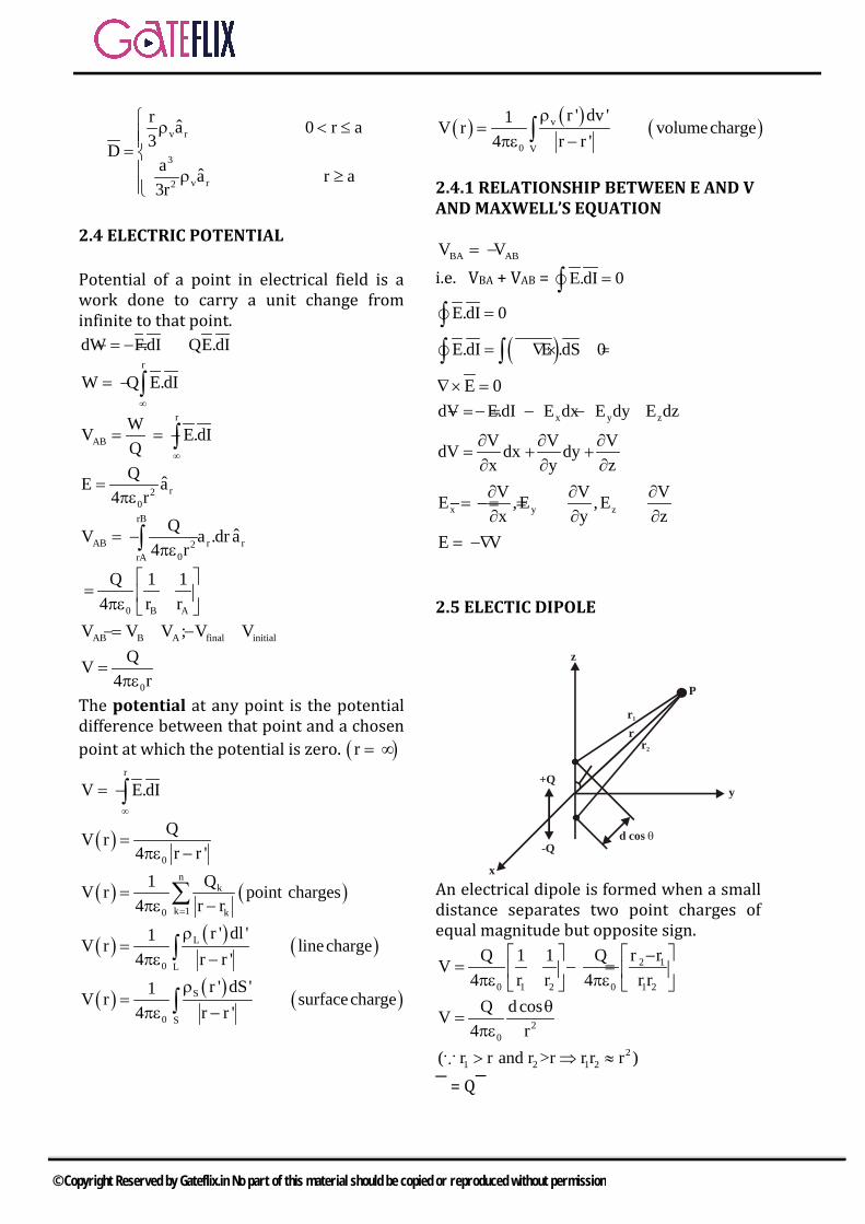
E V= −∇ 2.5 ELECTIC DIPOLE
+Q
-Qd cos θ
r1
rr2
P
x
y
z
An electrical dipole is formed when a small distance separates two point charges of equal magnitude but opposite sign.
2 1
0 1 2 0 1 2
r rQ 1 1 QV4 r r 4 r r
−= − = πε πε
20
Q d cosV4 r
θ=
πε
21 2 1 2( r r and r >r r r r )> ⇒ ≈
= Q
© Copyright Reserved by Gateflix.in No part of this material should be copied or reproduced without permission

dipole moment may be written as
r2
0
ˆp.aV4 r
=πε
rV 1 Vˆ ˆE V a ar r θ
∂ ∂ = −∇ = − + ∂ ∂θ
r3 30 0
Qd cos Qdsinˆ ˆa a2 r 4 r θ
θ θ= +
πε πε
( )r30
p ˆ ˆE 2cos a sin a4 r θ= θ + θ
πε
An electric flux line is an imaginary path or line drawn in such a way that its direction at any point is the direction of the electric field at that point.
2.6 ENERGY DENSITY IN ELECTROSTATIC FIELDS
Work done to carry charges Q1, Q2 and Q3 in a free space WE = W1+ W2 + W3 = 0 + Q2 V21 + Q3 (V31 + V32) If the charges were positional in reverse order, WE = W3 + W2 + W1 = 0 + Q2 V23 + Q1 (V12 + V13) 2WE = Q1(V12+V13)+Q2(V21+V23)+Q3 (V31+V32) = Q1 V1 + Q2 V2 + Q3 V3
WE = 21 (Q1 V1 + Q2 V2 + Q3V3)
n
E k kk 1
1W Q V2 =
= ∑ (in joules)
E L1W Vdl2
= ρ∫ (linecharge)
E S1W VdS2
= ρ∫ (surface charge)
E V1W dV2
= ρ∫ (volume charge)
( )EV
1W .D V.dv2
= ∇∫from Maxwell’s eq.
( ).VA A. V V .A∇ = ∇ + ∇ by vectoridentities
( ).A V .VA A. V∇ = ∇ − ∇
( ) ( )EV V
1 1W .VD dv D. V dv2 2
= ∇ − ∇∫ ∫
( ) ( )EV V
1 1W VD .dS D. V dv2 2
= − ∇∫ ∫
( ) ( )EV V
1 1W D. V dv D.E dv2 2
= − ∇ =∫ ∫2
E 01 1W D.E dv E dv2 2
= = ε∫ ∫The current density at a given point is the current through a unit normal area at that point. = - e m u eE= −
τeu Emτ
= −
V neρ = − Thus the conduction current density is
= ρvu = 2ne E E
mτ
= σ
2.6.1 CONDUCTORS
A perfect conductor cannot contain an electrostatic filed within it. = 0, ρv = 0, Vab = 0 inside a conductor
E = Vl
J = IS
VEl
σ= σ =
V lRI S
= =σ
clS
ρ=
E.dIVRI E.dS
= =σ∫
∫v vdvE.u E. u dvρ = ρ∫ ∫ Rate of change of
energy P = E.Jdv∫Which is known as Joule’s law. The power density Wp (in watts/m3) is given by the integrand in eq. That is,
© Copyright Reserved by Gateflix.in No part of this material should be copied or reproduced without permission

2P
dPW E.J E ( J= E)dv
= = = σ σ
2.7 CONTINUITY EQUATION
inout
dQI J.dSdt
−= =∫
S v
J.dS .Jdv= ∇∫ ∫
vinv
V V
dQ d dv dvdt dt t
∂ρ−= − ρ = −
∂∫ ∫
v
V V
.Jdv dvt
∂ρ∇ = −
∂∫ ∫
V.Jt
∂ρ∇ = −
∂Current continuity Eq.
2.8 BOUNDRAY CONDITIONS
• Dielectric (εr1) and dielectric (εr2)• Conductor and dielectric• Conductor and free space
E.dI 0=∫encD.dS Q=∫ (Gauss Law)
t nE E E= +
1t 1n 2n 2th h0 E w E E E w
2 2∆ ∆
= ∆ − − − ∆
2n Inh hE E
2 2∆ ∆
+ +
E1t = E2t
1t 2t1t 2t
1 2
D DE E= = =ε ε
it 2t
1 2
D D .......(1)=ε ε
S 1n 2nQ S D S D S∆ = ρ ∆ = ∆ − ∆ 1n 2n SD D− = ρif ρs = 0 1n 2nD D= ……..(2)
1 r1
2 r2
tantan
θ ε=
θ ε
2.9 POISSON’S & LAPLACE’S EQUATIONS
Poisson’s and Laplace’s equations are easily derived from Gauss’s law (for a linear material medium) ∇. D = ∇ . εE = ρv where E = -∇ V ∇. ( ε∇ V) = ρv
∇2 V = - Vρε
(Poisson’s Equation in
electrostatics) for homogeneous and linear medium. ∇2 V = 0 Which is known as Laplace’s equation.
2.10 CAPACITANCES
A. Parallel- Plate Capacitor
Electrostatics
© Copyright Reserved by Gateflix.in No part of this material should be copied or reproduced without permission

d
0
1
2
dielectric ε plate area S
E
x
SQS
σ = ; S=area of cross section
xS ˆE ( a )ρ
= −ε
Electric filed between
plates
xQ aS
= −ε
V
1 d
x x2 0
Q QdE.dI a .dxaS S
= = − − = ε ε ∫ ∫Q SCV d
ε= =
22
E1 1 QW CV QV2 2 2C
= = =
2 2
E 2 2 2 2V
1 Q Q SdW dv2 S 2 S
ε= ε =
ε ε∫2 2Q d Q 1 QV
2 S 2C 2 = = = ε
B. Coaxial Capacitor
+++ ++
++
dielectric ε--- - - - - -
--
-----
L
a
b
Q E.dS E 2 Lρ= ε = ε πρ∫
E = Q2 Lπερ
V = -1 a
2 b
Q ˆ ˆE.dI a .d a2 L ρ ρ ρ
= − πρ
∫ ∫
= Q b1n2 L aπρ
Q 2 LC bV 1na
πε= =
C. Spherical Capacitor
+++ ++
++
dielectric ε
---- - - - -
--
-----a
b
Q = 2rE.dS E 4 rε = ε π∫
r2
Q ˆE a4 r
=πε1 a
r r22 b
Q ˆ ˆV E.dI a .dra4 r
= − = − πε ∫ ∫Q 1 1
4 a b = − πε
Q 4C 1 1Va b
πε= =
−
E.dIVRI E.dS
= =σ∫
∫E.dSQC
V E.dI
ε= = ∫
∫
RC ε=
σ =Relaxation Time
2.11 METHOD OF IMAGES
The image theory states that a given charge configuration above an infinite grounded perfect conducting plane may be
Electrostatics
© Copyright Reserved by Gateflix.in No part of this material should be copied or reproduced without permission

replaced by the charge configuration itself, its image, and equipotential surface in place of the conducting plane.
A. A Point Charge Above Grounded Conducting Plane
V = 0
r1
r2
z
+Q
-Q
P(x, y, z)
E E E+ −= +1 2
3 30 1 0 2
Qr Qr4 r 4 r
−= +
πε πε
( )( )
( )( )
x y z x y z3/2 3/22 22 2 2 20
ˆ ˆ ˆ ˆ ˆ ˆxa ya z h a xa ya z h aQE4 x y z h x y z h
+ + − + + + = − πε + + − + + +
V V V+ −= +
( ) ( )1/2 1/22 22 2 2 20
Q 1 14 x y z h x y z h
= − πε + + − + + +
S n 0 n z 0D E =ρ = = ε
3/22 2 2
Qh
2 x y h
−=
π + +
Electrostatics
© Copyright Reserved by Gateflix.in No part of this material should be copied or reproduced without permission

3.1 INTRODUCTION
Magnetostatics is the study of magnetic fields in systems where the currents are steady (not changing with time). It is the magnetic analogue of electrostatics, where the charges are stationary. The magnetization need not be static; the equations of magnetostatics can be used to predict fast magnetic switching events that occur on time scales of nanoseconds or less.
Term Electric Magnetic
Basic law 1 2
r2
Q Q ˆF a4 r
=πε
(Coulomb’s
Law)
encD.dS Q=∫ (GaussLaw)
0 R2
ˆIdI adB4 R
µ ×=
π(Biot-
Savart’s Law)
encH.dI I=∫ (Ampere’sLaw)
Force law 𝐹𝐹 = Q𝐸𝐸 𝐹𝐹 = Q𝑢𝑢 × 𝐵𝐵 Source element dQ Q𝑢𝑢 = I 𝑑𝑑𝑑𝑑 Field intensity ( )VE V / m
l= ( )IH A / m
l=
Flux density ( )2D C / mSΨ
= ( )2B Wb / mSΨ
=
Relationship between fields D = ε E B = µ H
Potentials E = -∇ V
LdlV4 rρ
=πε∫
H = -∇Vm (J = 0) IdIA
4 Rµ
=π∫
Flux
D.dSΨ = ∫Q CVΨ = = dVI Cdt
=
B.dSΨ = ∫LIΨ =
dIV Ldt
=
Energy density E
1W D.E2
= m1W B.H2
=
Poisson’s equation 2 vV ρ∇ = −
ε
2A J∇ = −µ
3 MAGNETOSTATICS
© Copyright Reserved by Gateflix.in No part of this material should be copied or reproduced without permission

3.2 BIOT – SAVATRT’S LAW
dI
I
R
PdH (in ward)
Biot – Savart’s law states that the magnetic filed intensity dH produced at a point P, as shown in Figure by the differential current element I dl
2
IdlsindHR
αα
2
kldlsindHR
α=
2
IdlsindH4 R
α=
π
R2 3
ˆIdl a IdI RdH4 R 4 R× ×
= =π π
Current elements I dI = K dS = J dv
R2
L
ˆIdl aH4 R×
=π∫ (linecurrent)
R2
S
ˆK dS aH4 R
×=
π∫ (surfacecurrent)
R2
V
ˆJ dv aH4 R×
=π∫ (volumecurrent)
3.3 MAGNETIC FILED INTENSITY 1) Due to current carrying conductor
3
Idl RdH4 R×
=π
But 𝑑𝑑𝑑𝑑 = dz 𝑎𝑎z and 𝑅𝑅 = zˆ ˆa za ,soρρ −
ˆdI R dz aϕ× = ρ
3/22 2
I dz ˆH a4 z
ϕ
ρ=
π ρ + ∫
Letting z = ρ cot α, dz = - ρ cosec2 α dα, and eq. Becomes
z
PH (into the page)
R
B
dI
A
O
z
2
1
1
2
2 2
3 3
I cos ec d ˆH a4 cos ec
α
ϕα
ρ α α= −
π ρ α∫
2
1
I a sin d4
α
ϕα
= − α απρ ∫
( )2 1I ˆH cos cos a
4 ϕ= α − απρ
General eq.
I ˆH a2 φ=πρ
due to a infinite length conductor
lˆ ˆ ˆa a aϕ ρ= × 2) Due to a ring current conductor
𝑑𝑑𝑑𝑑 = 3
IdI R4 R×
π
where ( ) ( )ˆdI = d a ,R 0,0,h x, y,0ϕρ ϕ = − zˆ ˆa ha andρ= −ρ +
zˆ ˆ ˆa a a
dI R 0 d 00 h
ρ ϕ
× = ρ ϕ−ρ
2zˆ ˆh d a d aρ= ρ ϕ +ρ ϕ
P(0, 0, h) dHz
dHp
R
y
xI
z
© Copyright Reserved by Gateflix.in No part of this material should be copied or reproduced without permission

( )2z3/22 2
I ˆ ˆdH h d a d a4 h
ρ= ρ ϕ +ρ ϕ π ρ +
z zˆ ˆdH a dH aρ ρ= +2 2
zz z 3/22 2
0
ˆI d aˆH dH a4 h
π ρ ϕ= =
π ρ + ∫ ∫
2z
3/22 2
ˆI 2 a
4 h
ρ π=
π ρ + 2
z2 2 3/2
ˆI aH2[ h ]
ρ=
ρ +
3) Along the axis of solenoid
zP
dz
a
x
1
2
l
( )2 1 zNI ˆH cos cos a2l
= θ − θ
[ ] [ ] 2/322
2
2/322
2
zza2dznaI
za2adlIdH
+=
+=
where dL = ndz = (N/l) dz. tan θ = a /z; that is,
2dz a cosec qdq= −3/22 2
2
z asin d
a
+ = − θ θ
θθ−= dsin2nIdHz
∫θ
θ
θθ−=2
1
dsin2nIHz
( )2 1 znI ˆH cos cos a2
= θ − θ
as required. Substituting n = N / l gives At the center of the solenoid,
2 11/42 2
l / 2cos cosa l / 4
θ = = − θ +
z1/22 2
I nl ˆH a2 a l / 4
= +
If l >> a or Q2 = 00, Q1 = 800
z zNIˆ ˆn I a al
= =
3.4 AMPERE’S CIRCUIT LAW – MAXEWLL’S EQUATION
Ampere’s circuit law states that the line integral of the tangential component of H around a closed path is the same as the net current Ienc enclosed by the path.
Amperian pathy
x
z
IdI
0P
encH.dI I=∫( )enc
L S
I H.dI H . dS= = ∇×∫ ∫
encS
I J.dS= ∫H J∇× = =Volume current density (A/m2)
Maxwell’s third Eq.
3.4.1 APPLICATIONS OF AMPERE’S LAW
To determine 𝑑𝑑 for some symmetrical current distribution (as in Gauss’s Law)
A. Infinite Line Current ˆ ˆI H a . d a H d H .2ϕ ϕ ϕ ϕ ϕ= ρ ϕ = ρ ϕ = πρ∫ ∫
I ˆH a2 ϕ=πρ
B. Infinite Sheet of Current
© Copyright Reserved by Gateflix.in No part of this material should be copied or reproduced without permission

Amperian path
1
2
3
4
K = K ay y
x
y
z
a
b
Uniform current density 𝐾𝐾 =ky 𝑎𝑎y
enc yH.dI I K b= =∫
0 x
0 x
ˆH a z 0H
ˆH a z 0>
= − <
2 3 4 1
1 2 3 4
H.dI H.dI
= + + +
∫ ∫ ∫ ∫ ∫
( ) ( )( ) ( )0 00 a H b 0 a H (b)= − + − − + +
02H b=
y x
y x
1 ˆK a , z 02H
1 ˆK a , z 02
>= − <
n
1 ˆH K a2
= ×
C. Infinity Long Coaxial Transmission
Line Amperian path
L3
t
-I
L4
z - axis
L1
L2
I
a
b
For region 0 ≤ ρ ≤ a, we apply Ampere’s
law to path L1, giving
1
encL
H.dI I J.dS= =∫ ∫
z z2
I ˆ ˆJ a ,dS d d aa
= = ρ ϕ ρπ
enc 2
II J.dS d da
= = ρ ϕ ρπ∫ ∫ ∫
22
2 2
I Ia a
ρ= πρ =π
2
2
IH dl H 2aϕ ϕ
ρ= πρ =∫
2a2IHπρ
=φ
For region a ≤ ρ ≤ b, we use path L2 as the Amperian path.
∫ ==1L
enc IIdI.H
I2H =πρφ
πρ
=φ 2IH
For region b ≤ ρ ≤ (b + t), we use path L3, getting
∫ =φπ= φ encI2.HdI.H
2 2
enc 2
bI I 1t 2bt
ρ −= − +
2 2
2
I bH 12 t 2btϕ
ρ −= − πρ +
4L
H.dI I I 0= − =∫
2
2 2
2
I a , 0 a2 a
I a , a b2H
I b ˆ1 a , b b t2 t 2bt
0, b t
ϕ
ϕ
ϕ
ρ ≤ ρ ≤ π ≤ ρ ≤ πρ= ρ − − ≤ ρ ≤ + πρ − ρ ≥ +
D. TOROID It has N turns and carries current I.
Determine H inside and outside the toroid
H
I2 a
0 a b b+t
I2 b
© Copyright Reserved by Gateflix.in No part of this material should be copied or reproduced without permission
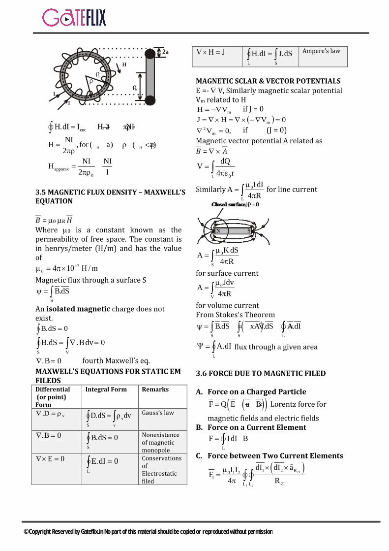
H
II
2a
0
0
encH.dI I H.2 NI= → πρ =∫0 0
NIH ,for ( a) ( a)2
= ρ − < ρ < ρ +πρ
apporax0
NI NIH2 l
= =πρ
3.5 MAGNETIC FLUX DENSITY – MAXWELL’S EQUATION
𝐵𝐵 = µ0 µR 𝑑𝑑 Where µ0 is a constant known as the permeability of free space. The constant is in henrys/meter (H/m) and has the value of
m/H104 70
−×π=µ Magnetic flux through a surface S
S
B.dSψ = ∫An isolated magnetic charge does not exist.
0dS.B =∫∫∫ =∇=VS
0dvB.dS.B
0B. =∇ fourth Maxwell’s eq. MAXWELL’S EQUATIONS FOR STATIC EM FILEDS Differential (or point) Form
Integral Form Remarks
vD. ρ=∇ ∫ ∫ρ=S v
vdvdS.D Gauss’s law
0B. =∇ ∫ =S
0dS.B Nonexistence of magnetic monopole
0E =×∇ ∫ =L
0dI.E Conservations of Electrostatic filed
JH =×∇ ∫∫ =SL
dS.JdI.H Ampere’s law
MAGNETIC SCLAR & VECTOR POTENTIALS E =- ∇ V, Similarly magnetic scalar potential Vm related to H
mVH −∇= if J = 0 ( ) 0VHJ m =∇−×∇=×∇=
,0Vm2 =∇ if (J = 0)
Magnetic vector potential A related as 𝐵𝐵 = ∇ × 𝐴𝐴
∫ πε=
L 0r4dQV
Similarly 0
L
IdIA4 Rµ
=π∫ for line current
0
S
K dSA4 R
µ=
π∫for surface current
0
V
JdvA4 Rµ
=π∫
for volume current From Stokes’s Theorem
( )S S L
B.dS xA .dS A.dIψ = = ∇ =∫ ∫ ∫
∫=ΨL
dI.A flux through a given area
3.6 FORCE DUE TO MAGNETIC FILED
A. Force on a Charged Particle
( )( )F Q E u B= + × Lorentz force for
magnetic fields and electric fields B. Force on a Current Element
L
F IdI B= ×∫C. Force between Two Current Elements
( )21
1 2
1 2 R0 1 21
21L L
ˆdI dI aI IF4 R
× ×µ=
π ∫ ∫
© Copyright Reserved by Gateflix.in No part of this material should be copied or reproduced without permission

3.7 MAGNETIC TORQUE AND MOMENT
The torque T (or mechanical moment of force) on the loop is the vector product of the force F and the moment arm r. T = r × F T = | F0 | ω sin α T = BI l w sin α m = I S an. The magnetic dipole moment is the product of current and area of the loop; its direction is normal to the loop. T = m × B A MAGNETIC DIPOLE
A = 0I dI4 rµπ ∫ 0 r
2
m aA4 r
µ ×=
π
( )0r
m ˆ ˆB 2cos a sin aˆ4 r3 θ
µ= θ + θ
π
3.8 MAGNETIC BOUNDRAY CONDITIONS
∫ = 0dS.B
H.dI I=∫ 0SBSB n2n1 =∆−∆ for cylindrical close
surface on boundary n2n1 BB = or n22n11 HH µ=µ
first Boundary conditions
1t 1n 2n 2th hK. w H . w H . H . H .
2 2∆ ∆
∆ = ∆ + + −
2n 1nh hw H . H .
2 2∆ ∆
∆ − −
1t 2tH H K− = Second Boundary conditions
KBB
2
t2
1
t1 =µ
−µ
( ) KaHH 12n21 =×−
if k = 0 t2t1 HH = or 2
t2
1
t1 BBµ
=µ
22n2n111 cosBBBcosB θ===θ
22
2t2t11
1
1 sinBHHsinBθ
µ===θ
µ
2
1
2
1
tantan
µµ
=θθ
Law of refraction for magnetic
flux lines at a boundary with no surface current
3.9 INDUCTOR AND INDUCTANCES
Ψ=λ N flux linkage λ I∝λ or LI=λ
IN
IL Ψ
=λ
= inductance of circuit.
2m LI
21W =
2m
IW2L =
∫=Ψ1S
212 dS.B
flux linkage from S, due to I2
2
121
2
1212 I
NI
M Ψ=
λ=
mutual inductance
1
212
1
2121 I
NI
M Ψ=
λ=
M12 = M21
1
11
1
111 I
NI
L Ψ=
λ=
2
22
2
222 I
NI
L Ψ=
λ=
Total magnetic energy in magnetic filed m 1 2 3W W W W= + +
2 21 1 2 2 12 1 2
1 1L I L I M I I2 2
= + ±
Relationship bet parameters
RC = σε and Lext C = µε
3.10 MAGNETIC ENERGY
© Copyright Reserved by Gateflix.in No part of this material should be copied or reproduced without permission

Sibilantly to the energy in an electrostatic filed.
2E
1 1W . dv E dv2 2
= = ε∫ ∫D E
2m LI
21W =
Consider a differential volume in a magnetic field as shown in Figure. Let the volume be covered with conducting sheets at the top and bottom surface with current ∆I.
IzxH
IL
∆∆∆µ
=∆∆Ψ
=∆
where ∆I = H ∆y. Substituting eq. into eq. we have
zyxH21IL
21W 22
m ∆∆∆µ=∆∆=∆
vH21W 2
m ∆µ=∆
The magnetostatic energy density wm ( in J /m3) is defined as
2m
0vm H21
vWlimw µ=∆∆
=→∆
µ==µ=
2BH.B
21H
21w
22
m
Thus the energy in a magnetostatic field in a linear medium is
∫= dvwW mm
∫∫ µ== dvH21dvH.B
21W 2
m
© Copyright Reserved by Gateflix.in No part of this material should be copied or reproduced without permission

Q.1 The electric field on the surface of a perfect conductor is 2 V/m. The conductor is immersed in water with 080∈= ∈ . The surface charge density on the conductor is a) 20C / mb) 22C / mc) 11 21.8 10 C / m× −d) 9 2101.4 m1 C /−×
9( 10 ) / (36 )F / m)∈= π [GATE – 2002]
Q.2 if the electric field intensity is given by x y zE (xu yu zu )= + + volt/m the potential difference between X (2, 0, 0) and Y (1, 2, 3) isa) + 1 volt b) – 1 volt c) + 5 volt d) + 6 volt
[GATE – 2003]
Q.3 The unit H∇× is a) Ampere b) Ampere/meterc) Ampere/meter2 d) Ampere-meter
[GATE – 2003]
Q.4 A parallel plate air – filled capacitor has plate area of 4 210− m and plate separation of 310− m .It is connected to a 0.5 V, 3.6 GHz source. The magnitude of the displacement current is
90( 1/ 36 10 / )−ε = π× F m
a) 10 mA b) 100 mAc) 10 A d) 1.59 mA
[GATE – 2004]
Q.5 If C is a closed curve enclosing a surface S, then the magnetic field intensity H
r, the current density J
r
and the electric flux density Dr
are related by
a) S C
DH.dS J .dlt
∂= + ∂
∫ ∫ ∫
b) C S
DH.dl J .dSt
∂= + ∂
∫ ∫∫
c) S C
DH.dS J .dlt
∂= + ∂
∫∫ ∫
d) C S
DH.dl J .dSt
∂= + ∂
∫ ∫ ∫
[GATE – 2007]
Q.6 For static electric and magnetic fields in an inhomogeneous source-free medium, which of the following represents the correct form of two of Maxwell’s equations? a) .E 0∇ =b) .E 0∇ = B 0 .B 0∇× = ∇ =c) E 0∇× =d) E 0 B 0 .B 0∇× = ∇× = ∇ =
[GATE – 2008]
Q.7 A magnetic field in air is measured
to be 0x yˆ ˆB B y x
x2 y2 x2 y2
= − + +
what current distribution leads to this field? [Hint : the algebra is trivial in cylindrical coordinates.]
a) 02 2
0
B 1j , r 0x y
Z = − ≠ µ +
b) 02 2
0
B 2j , r 0x y
Z = − ≠ µ +
c) j 0, r 0= ≠
d) 02 2
0
B 1j , r 0x
Zy
= ≠ µ +
[GATE – 2009]
GATE QUESTIONS
© Copyright Reserved by Gateflix.in No part of this material should be copied or reproduced without permission

Q.8 If a vector field
V is related to another vector field
A through V xA= ∇
which of the following is true? Note: C and CS refer to any closed contour and any surface whose boundary is C.
a) C SC
V.dl A.dS=
∮ ∬
b) C SC
A.dl V.dS=
∮ ∬
c) C SC
V.dl A.dS∇× = ∇×
∮ ∬
d) C SC
A.dl V dS∇× = ×
∮ ∬
[GATE – 2009]
Q.9 Two infinitely long wires carrying current are as shown in the figure below. One wire is in the y-z plane and parallel to the y-axis. The other wire is in the x-y plane and parallel to the x-axis. Which components of the resulting magnetic field are non-zero at the origin?
a) x, y, z componentsb) x, y componentsc) y, z componentsd) x, z components
[GATE – 2009]
Q.10 Consider a closed surface S surrounding a volume V. If
r is the position vector of a points inside S, with n the unit normal on S, the
value of the integral ˆ5 .∫∫
r n dS S
a) 3 V b) 5 Vc) 10 V d) 15 V
[GATE – 2011]
Q.11 The electric and magnetic fields for a TEM wave of frequency 14 GHz in a homogeneous medium of relative permittivity εr and relative permeability µ =r 1 are given by
( )j t 280 yp zˆE E e u V / mω − π=
( )j t 280 yxˆH 3e u A / mω − π=
Assuming the speed of light in free space to be × 83 10 m/s, intrinsic impedance of free space to be π120 , the relative permittivity εr of the medium and the electric field amplitude 𝐸𝐸𝑃𝑃 are a) ρε = = πr 3, E 120 b) ρε = = πr 3, E 360
c) ρε = = πr 9, E 360
d) ρε = = πr 9, E 120 [GATE – 2011]
Statement for linked answer questions 12 and 13
An infinitely long uniform solid wire of radius a carries a uniform dc current of density j .
Q.12 The magnetic field at a distance r from the centre of the wire is proportional to a) r for r < a and 1/r2 for r > ab) 0 for r < a and 1/r for r > ac) r for r < a and 1/r for r > ad) 0 for r < a and 1/r2 for r > a
[GATE – 2012]
Q.13 A hole of radius b(b<a) is now drilled along the length of the wire at a distance d from the centre of the wire as shown below. a) uniform and depends only onb) uniform and depends only on bc) uniform and depends on both b
and dd) non uniform
© Copyright Reserved by Gateflix.in No part of this material should be copied or reproduced without permission

[GATE – 2012]
Q.14 The direction of vector A is radially
outward from the origin, withnA =kr where 2 2 2 2r x y z= + + and k
is a constant. The value of n for which 0∇ =.A is
a) – 2 b) 2 c) 1 d) 0
[GATE – 2012]
Q.15 The force on a point charge +q kept at a distance d from the surface of an infinite grounded metal plate in a medium of permittivity ∈ is
a) 0
b) 2
2
q16π d
way from the plate
c) 2
2
q16π d
towards the plate
d) 2
2
q4π d
towards the plate
[GATE – 2014-1] Q.16 A region shown below contains a
perfect conducting half-space and air. The surface current sK
on the surface of the perfect conductor is
sK x2=
amperes per meter. The
tangential Hr
field in the air just above the perfect conductor is
a) (x z)2+ amperes per meter
b) x2 amperes per meter c) z2− amperes per meter d) z2 amperes per meter
[GATE – 2014-3] Q.17 The electric field (assumed to be
one-dimensional) between two points A and B is shown. Let AΨ and
BΨ be the electrostatic potentials at A and B, respectively. The value of
BΨ . ‒ AΨ in Volts is ----------
[GATE – 2014-4]
Q.18 If 3 2 2 2E (2y 3yz )x (6xy 3xz )= − −− −
y (6xyz)z+ is the electric field in a source free region, a valid expression for the electrostatic potential is a) 3 2xy yz− b) 3 22xy xyz−
c) 3 2y xyz− d) 3 22xy 3xyz− [GATE – 2014-4]
Q.19 Consider a straight, infinitely long,
current carrying conductor lying on the z-axis. Which one of the following plots (in linear scale) qualitatively represents the dependence of Hφ on r, where Hφ is the magnitude of the azimuthal component of magnetic field outside the conductor and r is the radial distance from the conductor?
a) b)
© Copyright Reserved by Gateflix.in No part of this material should be copied or reproduced without permission

c) d)
[GATE – 2015-1]
Q.20 A vector P
is given by 3 2 2 2
x y zP=x ya x y a x yza .− −
Which one of the following statements is TRUE? a) P
is solenoidal, but not irrotational
b) P
is irrotational, but not solenoidal,
c) P
is neither solenoidal nor irrotational
d) P
is both solenoidal and irrotational
[GATE – 2015-1] Q.21 In a source free region in vacuum, if
the electrostatic potential 2φ 2x= 2 2y cz+ + , the value of constant c
must be [GATE – 2015-2]
Q.22 A vector field 2
zD 2 a zaρ= ρ + exists inside a cylindrical region enclosed by the surfaces ρ 1, z 0= = and z = 5. Let S be the surface bounding this cylindrical region. The surface
integral of this field on S s
D.ds ∫∫
is _______. [GATE – 2015-3]
Q.23 Concentric spherical shells of radii 2
m, 4 m, and 8 m carry uniform surface charge densities of 20 nC/m2, -4nC/m2 and ρs, respectively. The value of ρs (nC/m2) required to ensure that the electric flux density D 0=
at radius 10 m is ___________
[GATE – 2016-1] Q.24 The current density in a medium is
given by
2r2
400sinθ ˆJ a Am2π(r 4)
−=+
The total current and the average current density flowing through the portion of a spherical surface r = 0.8
m, π πθ ,0 2π12 4
≤ ≤ ≤∅ ≤ are given,
respectively, by a) 15.09 A, 12.86 Am-2 b) 18.73 A, 13.65 Am-2 c) 12.86 A, 9.23 Am-2 d) 10.28 A, 7.56 Am-2
[GATE – 2016-1]
Q.25 A uniform and constant magnetic field B = z B exists in the direction in vacuum. A particle of mass m with a small charge q is introduced into this region with an initial velocity
x zˆ ˆv v x z .v= + . Given that B, m, q, xv and zv are all non-zero, which one of the following describes the eventual trajectory of the particle? a) Helical motion in the z direction. b) Circular motion in the xy plane. c) Linear motion in the z direction. d) Linear motion in the x direction
[GATE – 2016-2]
Q.26 The parallel-plate capacitor shown in the figure has movable plate. The capacitor is charged so that the energy stored in it is E when the plate separation is d. The capacitor is then isolated electrically and the plates are moved such that the plate separation becomes 2d.
© Copyright Reserved by Gateflix.in No part of this material should be copied or reproduced without permission

At this new plate separation, what is the energy stored in the capacitor, neglecting fringing effects?
a) 2E b) 2 E c) E d) E/2
[GATE – 2016-2] Q.27 Faraday's law of electromagnetic
induction is mathematically described by which one of the following equations? a) .B∇
= 0 b) .D∇
= ρv
c) BEt
∂∇× =
∂
d) DH σEt
∂∇× = +
∂
[GATE – 2016-3]
Q.28 Consider the charge profile shown in the figure. The resultant potential distribution is best described by
a)
b)
c)
d)
[GATE – 2016-3]
Q.29 Two conducting spheres S1 and S2 of radii a and b (b>a) respectively, are placed far apart and connected by a long, thin conducting wire, as shown in the figure.
For some charge placed on this structure, the potential and surface electric field on S1 are Va and Ea, and that on S2 are Vb and Eb, respectively, which of the following is CORRECT?
a)Va = Vb and Ea < Eb
b) Va > Vb and Ea > Eb
c) Va = Vb and Ea > Eb
d) Va > Vb and Ea = Eb
[Gate-2017, Set-2] Q.30 An electron (q1) is moving in free space with velocity 105 m/s towards a stationary electron (q2) far away.
© Copyright Reserved by Gateflix.in No part of this material should be copied or reproduced without permission

The closest distance that this moving electron gets to the stationary electron before the repulsive force diverts its path is ___________ ×10-8m. [Given, mass of electron m = 9.11×1031 kg, charge of electron e = -1.6 x 10⁻¹⁹C, and permittivity
( ) 90 1/ 36 X10 F / m−ε = π ]
[Gate-2017, Set-2]
Q.31 If the vector function
( ) ( ) ( )x 1 y 2 z 3ˆ ˆ ˆF a 3y k z a k x 2z a k y z= − + − − +
is irrotational, then the values of the constants k1, k2 and k3 respectively, are
a)0.3, -2.5,0.5
b) 0.0, 3.0, 2.0
c) 0.3, 0.33, 0.5
d) 4.0, 3.0, 2.0
[Gate-2017, Set-2]
Q.32 The figures show diagrammatic representations of vector fields
X, Y→ →
and Z→
respectively of Which one of the following choices is true?
(A) V.X 0, V Y 0, V Z 0→ → → = × ≠ × =
(B) V.X 0, V Y 0, V Z 0→ → → ≠ × = × ≠
(C) V.X 0, V Y 0, V Z 0→ → → ≠ × ≠ × ≠
(D) V.X 0, V Y 0, V Z 0→ → → = × = × =
[Gate-2017(EE), Set-2]
Q.33 Consider an electron, a neutron and a proton initially at rest and placed along a straight line such that the neutron is exactly at the center of the line joining the electron and proton. At t = 0, the particles are released but are constrained to move along the same straight ling. Which of these will collide first?
a) The particles will never collideb) All will collide togetherc) Proton and neutrond) Electron and neutron
[Gate-2017(EE), Set-1]
© Copyright Reserved by Gateflix.in No part of this material should be copied or reproduced without permission

Q.34 Consider a solid sphere of radius 5 cm made of a perfect electric conductor. If one million electrons are added to this sphere, these electrons will be distributed. a) Uniformly over the entire volume of the sphere b) Uniformly over the outer surface of the sphere c) Concentrated around the center of the sphere d) Along a straight line passing through the center of the sphere.
[Gate-2017(EE), Set-2] Q.35 A thin soap bubble of radius R = 1 cm, and thickness a = 3.3 μm (a << R). is at a potential of 1 V with respect to a reference point at infinity. The bubble bursts and becomes a single spherical drop of soap (assuming all the soap is contained in the drop) of radius r. The volume of the soap in the thin bubble is 24 Rπ a and that of the
drop is 343
r− π . The potential hi
volts, of the resulting single spherical drop with respect to the same reference point at infinity is ______. (Given the answer up to two decimal places)
[Gate-2017(EE), Set-2]
Q.36 A solid iron cylinder is paced in a region containing a uniform magnetic field such that the cylinder ax’s is parallel to the magnetic field
direction, the magnetic field lines inside the cylinder will a) Bend closer to the cylinder axis b) Bend farther away from the axis c) remain uniform as before d) Cease to exist inside the cylinder
[Gate-2017(EE), Set-1] Q.37 The magnitude of magnetic flux density (B) in micro Teslas (μT ). At the center of a loop of were wound as a regular hexagon of side length 1 m carrying a Current (I = 1 A) and placed in vacumm as shown in the figure _____ (Give the answer up to two decimal places.)
[Gate-2017(EE), Set-1]
Q.38 A positive charge of 1nC is placed at (0, 0, 0.2) where all dimensions are in meters. Consider the x-y plane to be a conducting ground plane. Take 12
0 8.85 10 F/m.ε −= The Z component of the E field at (0, 0, 0.1) is closest to a) 899.18 V/m b) – 899.18 V/m c) 999.09 V/m d) – 999.09 V/m
[Gate-2018(EE)] Q.39 The capacitance of an air-filled parallel-plate capacitor is 60 pF. When a dielectric slab whose thickness is half the distance between the plates, is placed on one of the plates covering it entirely, the capacitance becomes 86 pF. Neglecting the fringing effects, the
© Copyright Reserved by Gateflix.in No part of this material should be copied or reproduced without permission

relative permittivity of the dielectric is ________ (up to 2 decimal places).
[Gate-2018(EE)]
1 2 3 4 5 6 7 8 9 10 11 12 13 14 (d) (c) (c) (a) (d) (d) (c) (b) (d) (d) (d) (c) (c) (a) 15 16 17 18 19 20 21 22 23 24 25 26 27 28 (c) (d) * (d) (c) (a) * * * (a) (a) (a) (c) (d) 29 30 31 32 33 34 35 36 37 38 39 (c) 5.058x
10-8 (b) (c) (b) (b) 10.03 (a) 0.69 (d) 2.53
ANSWER KEY:
© Copyright Reserved by Gateflix.in No part of this material should be copied or reproduced without permission
Q.1 (d) s
12 2
-9 2
D E 80. .280x2x8.854x10 c/m
=1.41x10 c/m
−
= ρ = ε = ε
=
Q.2 (c) V Edl= −∫
2 0 0
1 2 3
x y zxdxu ydyu zdzu
= − + + ∫ ∫ ∫
r r r
02 02 22
31 22 2 2X y z
= − + +
2 2 2 2 2 21 [2 1 0 2 0 3 ]2
= − − + − + −
1 10 52
V= − ×− =
Q.3 (c) DxH Jt
∂∇ = +
∂
J is current density = A/m2
Q. 4 (a) Displacement current
d dI AJ=D EA At t
∂ ∂= = ∈
∂ ∂
dI A Eω= ∈ VAd
ω= ∈
After putting values we get Id= 10 mA
Q.5 (d)
Q.6 (d)
Q.7 (c)
0 y xx yˆ ˆB B a a
x2 y2 x2 y2
= − + +
Convert to cylindrical coordinates and put x = r cos ϕ
x ra cos a sin aφ= φ − φ
siny r φ= ˆ ˆ ˆsin cos= +y r ra a aφ φ
Putting the values
0 ˆ=B B aφ
0
0
B ˆH aφ=µ
= constant
J xH x= ∇ = ∇ [constant]=0
Q.8 (b) This represents stoke’s theorem
( )C S S
A.dt xA .dS V.dS= ∇ =∫ ∫ ∫ ∫ ∫
Q.9 (d)
Q.10 (d)
S V
ˆ5r.nds .5rdv= ∇∫∫ ∫∫∫
(using
divergence theorem)
V
5 .rdv 5x3 15volt∇ = =∫∫∫
Q.11 (d) Given
( )j t 280 yp zˆE E e u V / mω − π=
( )j t 280 y
xˆH 3e u A / mω − π=
From given expression we conclude that
2280 πβ πλ
= =
1140
λ = meter
v f λ=
9 114 10 / sec140
m= × ×
81 10 / secv m= ×
EXPLANATIONS
© Copyright Reserved by Gateflix.in No part of this material should be copied or reproduced without permission
but, r r
cvµ
=∈
88 3 101 10
1 r
×× =
×∈
8r∴ ∈ = 0P
P 0
μ 1E μηH 9
×= = =
×
0
0
μ13
=
E 1 1203 3ρ⇒ = × π
120Eρ π∴ =
Q.12 (c) We know that magnetic flux density at a distance r from the wire is
0
2lBr
µπ
=
For 2.r a I J rπ< → = B r∝ for r < a (inside the wire)
for r > a , 2I J aπ= ×
so, 2
0
2J aB
rµ π
π=
1Br
∝= for r > a. (outside the wire)
Q.13 (c) It is uniform and depends on both b and d.
Q.14 (a) nA kr=
nrˆA kr a= (since it is radially
outward) .A∇ in spherical coordinate is
( )22
1.A r Arr r
∂∇ = +
∂
( )θ θ1 1A sinθ A
r sinθ r r sin θ r∂ ∂
+∂ ∂
( )2 n2
1.A r kr 0 0r r
∂∇ = + +
∂
( )n 22
k.A rr r
+∂∇ =
∂
So .A∇
will be zero if 2( )nrr
+∂∂
will
be zero, and 2( )nrr
+∂∂
will be zero if
2nr + will be constant and this is
possible if 2 0 2n n+ = ⇒ = −
Q.15 (C)
1 22
Qπ R
F Q14
=
( )
2 2
2 2
1 9 9F4π 16π d2d
=
Since the charges are opposite polarity the force between them is attractive.
Q.16 (D) Given medium (1) is perfect conductor Medium (2) is air ∴H1 = 0 From boundary conditions (H1 -H2)×an =Ks
1s x
n y
H 0ˆK 2a
a a=
==
—H2 x ay = 2 xa —(Hxax +Hyay + Hzaz )×ay = 2ax —Hxaz + Hzax = 2ax
∴ Hz = 2 zH=2a
Q.17 (-15)
A
© Copyright Reserved by Gateflix.in No part of this material should be copied or reproduced without permission
(0kV/cm, 20kV/cm) B
4(5 10 kV / cm,40kV / cm)−× 4
4
40 20E 20 (x 0) E 4 10 x 205 10−
−− = − ⇒ = × +
×
( )4/cmB 5 10
4AB
0A
V E.dI 4 10 x 20 dx−×
= = − × +− ∫ ∫
45 1024
0
x4 10 20x2
−×
= − × +
=
4 8 410 25 102 0 10 )( 2 5− −+ × ×− × × × 4 4(50 10 100 10 )− −= − × + × =
4150 10 kV−− × ABV VAB = -15V
Q.18 (d) Given
3 2x
2 2y z
ˆE (2y 3yz )aˆ ˆ(6xy 3xz )a 6xyza
−= − −
− +
By verification option (D) satisfy E= -∇V
Q.19 (c)
ΦIH
2πr=
r is the distance from current element.
ΦIHr
∞
Q.20 (a)
3 2 2 2x y zˆ ˆ ˆP x ya x y a x yza−= −
2 2 2x y 2xP 3 y x y 0− −= =∇ It is silenoidal
y
2
z
3 2 2
x
Px y z
x y x y x yz
ˆ ˆ ˆa a a∂ ∂ ∂
× =∂ ∂ ∂
− −
∇
2x y z
2 3( 2xyˆ ˆ ˆa ( x y) a az) ( 2xy x ) 0− + − −= − ≠−
So, P is solenoidal but not irrotational.
Q.21 (-3)
2 2 2x y z2 c+ +
x zyˆ ˆ ˆE 2y 2cφ 4xa za a− −= −∇ = − ∇E = 0 -4-2-2c=0 C=-3 Q.22 (78.53)
2ρ zˆ ˆρ aD za2 +=
( )V
sD.ds= .D dv∇∫∫ ∫
zD D1 1.D ( D )ρ ρ ρ z
∅ρ
∂ ∂∂∇ = ρ + +
∂ ∂∅ ∂
21 (ρ2ρ ) 0 1ρ ρ∂
= + +∂
21 2(3) 1ρ
= ρ +
6 1= ρ+
( ) ( )1 2π 5
ρ 0 0z 0V
.D dv 6ρ 1 ρdρd dz= ∅= =
∇ = + ∅∫ ∫ ∫ ∫
13 2
0
6ρ ρ3 2
(2 )(5)
π= +
( )V
12 10 .D dv 78.532
+ π ∇ =
= ∫
Q.23 (-0.25)
Consider a Gaussian surface a sphere of radius 10m To ensure D 0=
at radius 10m, the total charge enclosed by Gaussian surface is zero Qenc = 0
2 2 2
s2
s
20 2 4 4 P 80 P 0.25nc / m
⇒ × − × + ×
= ⇒ = −
Q.24 (a) Q.25 (a)
Force due to B on q is x B ˆF q(V B) q[ ](V y)V= × = −
⟹Helical motion in z-direction. Q.26 (a)
If capacitor is electrically isolated then charge is same
© Copyright Reserved by Gateflix.in No part of this material should be copied or reproduced without permission

We know 1 21 1 2 2
1 2
& C CC d C dV V
= =
If ‘d’ is doubled then C will be C/2 and V will be 2V
Given 2new
1 1 CE CV E .2 2 2
= ⇒ =
2 22 1(2V) CV 2E2
× × ==
Q.27 (c) Q.28 (d)
Electrical 0 d no d poq qε N X=- N Xε ε
= −
Potential ( )2
00
xψ x ε x2w
= −
Q.29 (c) Two spheres are joined with a conducting wire, the voltage on two spheres is same.
Va = Vb The capacitance of sphere ∝ radius
a
b
C aC b
=
We know Q = CV
a a
b b
2a 0
b2
0
a b
Q C aQ C b
1 aE 4 a b 11 bE a
4 bE E
= =
πε= = >
πε>
Q.30 5.058 (4.55-5.55)
Work done due to field and external agent must be zero
( )
2
19 219 5
08
1qV MV2
1.6x10 11.6x10 x mx 104 2
5.058x10 m
−−
−
=
− =πε γ
γ =
Q.31 (b)
curl F
= 0
1 2 3
i j k
0x x x
3y k z k x-2z -k y-z
∂ ∂ ∂=
∂ ∂ ∂−
( ) ( ) ( )3 1 2
1 2 3
i -k 2 j 0 k k k 3 0k 0,k 3,k 2
+ − + + − =
= = =
Q.32 (c)
X→
is radial and irrational and hence
V.X 0→≠ While y is rotational and its curl is
non
zero V Y 0→
× ≠
The field z is also rotational and hence
V Z 0 × ≠
© Copyright Reserved by Gateflix.in No part of this material should be copied or reproduced without permission

Q.33 (b)
Given that electron, neutron and proton are in a straight line
The electron will move towards proton and proton will more towards electron and force
will be same 1 22
04 Rq qF =π∈
. But
acceleration of electron will be more than proton as 4n C mass of electron < mass of proton. Since neutron are neutral they will not move. Thus electron will hit neutron first. Q.34 (b) Static charge resides only on the surface of a conductor. Therefore the electrons will be uniformly over the entire surface of the sphere.
Q.35 10.00-10.50
Charge must be same
( )2 3v
2
3
44 R a = p3
r = 3 3R a0.996 10
r
−
π π
= ×
The potential of thin bubble is 1 V.
20
20
02
03
0
QI =4 1 10
Q = 4 1 10 CPotential at soap drop,
QV =4 r4 10
4 0.99661010.03V
Ans : 10.00 to 10.50
−
−
−
−
π∈ × ×
π∈ × ×
π∈
π∈ ×=
π∈ ×=
Q.36 (a)
Iron being a ferromagnetic material, magnetic lines of force bend closer to cylindrical axis. Q.37 0.69 μT i = 1 A
( )01 2
Here B at point P is
B = sin sin4 d
Iθ + θ
π
© Copyright Reserved by Gateflix.in No part of this material should be copied or reproduced without permission

( )
( )
01 2
o2
o o
7
7 6
For each segment of hexagon (1, 2, 3, 4, 5, 6)
B = sin sin4 d
3, Where 12
and 306B = sin 30 sin 304 3
24 10 6 1
342
12 1.2010 103 30.69 μT
1
−
− −
⇒ θ + θπ
= =
θ = θ =
⇒ +π
π=
π
= =
=
I
Here d l l
I
T
B
Q.38 (d)
Given : Charge = 1nC at (0,0,0.2) . Since the charge is placed above conducting grounded plane there will be an image charge below the grounded conducting plane as per method of image concept
Electric field at any point is given by,
30
14
Q RER
ε
→→
→= =
π
R→
= displacement vector between charge to point of interest. Electric field at point P due to point charge +1nC ,
( ) ( ) ( )
( )
9
1 30
1
1 10 0 0 0 0 0.1 0.21
4 0.1
898.755V/m
x y za a aE
E
ε
→ → →−
→
→
− + − + −
=π
=
Electric field point P due to point charge -1nC.
( ) ( ) ( )
( )
9
2 30
1 10 0 0 0 0 0.1 0.21
4 0.399.86 V/m
→ → →−
→
− + − + −
=π
=
x y za a aE
ε
Total electric field at point P due to both charges.
1 2
898.755 99.86 998.61 V/m
E E E
E
→ →→
→
= +
= − = −
Q.39 2.53
Given : Capacitance of an air-filled parallel plate capacitor,
00
A 60pF ...(i)
Overall capacitance,86pF
= =
=eq
Cd
C
ε
From fig. 2, after filling with dielectric it has become series combination of two capacitances overall capacitance for series combination is given by,
1 2
1 2
0 01 2
86 pF ...(ii)
A Aand/ 2 / 2
From equation (ii),
= =+
= =
eq
r
C CCC C
C Cd dε ε ε
© Copyright Reserved by Gateflix.in No part of this material should be copied or reproduced without permission

( )
( )
0 0
0
0 0
A AA/ 2 / 2
A A / 2 1/ 2 / 2
rr
eqr r
d dCd
d d
ε ε εεε
ε ε ε ε
×= =
++
( )
( )86 120
1r
r
ε
ε=
+
( )86 1 120r rε ε+ =
86 34
2.529r
r
ε
ε
=
=
Hence, the relative permittivity of the dielectric is 2.53.
© Copyright Reserved by Gateflix.in No part of this material should be copied or reproduced without permission
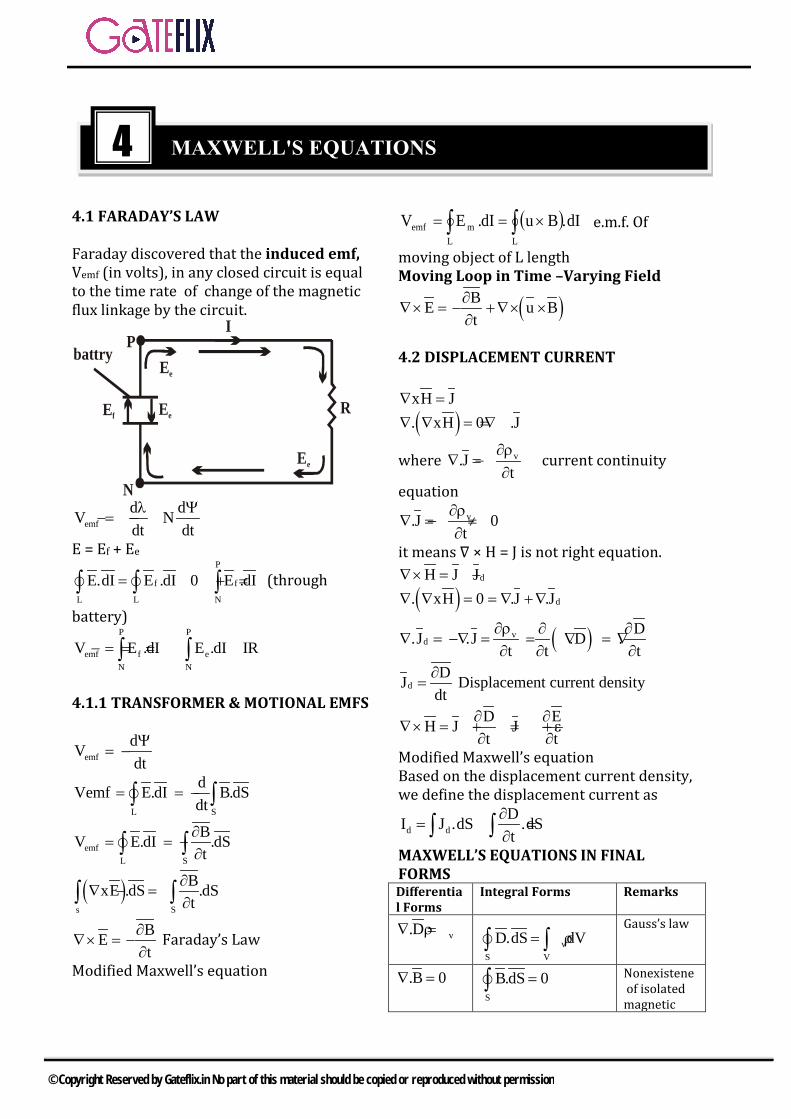
4.1 FARADAY’S LAW
Faraday discovered that the induced emf, Vemf (in volts), in any closed circuit is equal to the time rate of change of the magnetic flux linkage by the circuit.
I
R
N
Ef Ee
PEe
Ee
battry
emfd dV Ndt dtλ Ψ
= − −
E = Ef + Ee P
f f
L L N
E.dI E .dI 0 E .dI= + =∫ ∫ ∫
(through
battery) P P
emf f eN N
V E .dI E .dI IR= = − =∫ ∫
4.1.1 TRANSFORMER & MOTIONAL EMFS
emfdVdtΨ
= −
L S
dVemf E.dI B.dSdt
= = −∫ ∫
emfL S
BV E.dI .dSt
∂= = −
∂∫ ∫
( )s S
BxE .dS .dSt
∂∇ = −
∂∫ ∫BEt
∂∇× = −
∂ Faraday’s Law
Modified Maxwell’s equation
( )∫∫ ×==LL
memf dI.BudI.EV e.m.f. Of
moving object of L length Moving Loop in Time –Varying Field
( )BE u Bt
∂∇× = − +∇× ×
∂
4.2 DISPLACEMENT CURRENT
xH J∇ =
( ). xH 0 .J∇ ∇ = = ∇
where v.Jt
∂ρ∇ = −
∂current continuity
equation v.J 0t
∂ρ∇ = − ≠
∂
it means ∇ × H = J is not right equation. dH J J∇× = +
( ) d. xH 0 .J .J∇ ∇ = = ∇ +∇
( )vd
D.J .J .D .t t t
∂ρ ∂ ∂∇ = −∇ = = ∇ = ∇
∂ ∂ ∂
dDJ
dt∂
= Displacement current density
D EH J Jt t
∂ ∂∇× = + = + ε
∂ ∂Modified Maxwell’s equation Based on the displacement current density, we define the displacement current as
d dDI J .dS .dSt
∂= =
∂∫ ∫MAXWELL’S EQUATIONS IN FINAL FORMS Differential Forms
Integral Forms Remarks
v.D∇ = ρv
S V
D.dS dV= ρ∫ ∫
Gauss’s law
.B 0∇ =S
B.dS 0=∫ Nonexistene of isolated magnetic
4 MAXWELL'S EQUATIONS
© Copyright Reserved by Gateflix.in No part of this material should be copied or reproduced without permission

charge* BEt
∂∇× = −
∂ L S
E.dI B.dSt∂
= −∂∫ ∫
Faraday’s day
DH Jt
∂∇× = +
∂L S
DH.dI J .dSt
∂= + ∂
∫ ∫
Ampere’s circuit law
4.3 TIME – VARYING POTENTIALS
v
v
dvV4 Rρ
=πε∫
∫ πµ
=V R4
dvJA
[ ]v
v
dvV
4 Rρ
=πε∫
Retarded Electric potential [ ]
V
J dvA
4 Rµ
=π∫ ; Magnetic vector potential
Retarded Magnetic potential B xA= ∇
( )xE xAt∂
∇ = − ∇∂Ax E 0t
∂∇ + = ∂
AE Vt
∂+ = −∇∂
AE Vt
∂= −∇ −
∂Modified electric filed equation Electromagnetic wave equation
( )2v.E V .At
ρ ∂∇ = = −∇ − ∇
ε ∂
( )2 vV .At
ρ∂∇ + ∇ = −
∂ ε…….(1)
∇ × B = J + Dt
∂∂
Maxwell’s equation AA J V
t t∂ ∂ ∇×∇× = µ + εµ −∇ − ∂ ∂
2
2
V AJt t
∂ ∂ = µ −µε∇ −µε ∂ ∂ 2x xA ( .A) A∇ ∇ =∇ ∇ −∇
by vector identity
( )2
22
V AA .A Jt t
∂ ∂ ∇ −∇ ∇ = −µ +µε∇ +µε ∂ ∂ by compare
V.At
∂∇ = −µε
∂………(2)
Lorentz condition for potentials by (1) and (2)
22 V
2
VVt
ρ∂∇ −µε = −
∂ εThose are wave equations
22
2
VA Jt
∂∇ −µε = −µ
∂
t’ = t - µR
µε=
1u
4.4 TIME – HARMONIC FIELD
A time – harmonic field is one carries periodically or sinusoidally with time. z x jy r= + = ∠ϕ z = rej∅ = r (cos + j sin ∅) r = |z| = x2 + y2
1 ytan x
−∅ =
z* = x – jy = r ∠-∅ = re−j∅ ∅ = ωt + θ Time varying rej∅ = rejθejωt Re ( rej∅) = r cos(ωt + θ) Im ( rej∅) = r sin(ωt + θ) The complex term I0ejθ, which result from dropping the time factor ejωt in I(t), is called the phasor current, denoted by Is, that is, Is = I0ejθ = I0 ∠θ Where the subscript s denotes the pharos form of I(f). Thus I(t) = I0 cos (ωt + θ), the instantaneous form, can be expressed as I(t) = Re (Isejωt) In general, a phasor could be scalar or vector. If a vector A(x, y, z, t) is a time – harmonic field, the phasor from of A is As(d, y, z); the two quantities are related as A = Re ( Asejωt) For example, if A = Ao cos ( ωt – βx) ay, we can write A as
© Copyright Reserved by Gateflix.in No part of this material should be copied or reproduced without permission

A = Re ( Ao e-jβx ay ejωt) At t
∂ ∂=
∂ ∂Re (Asejωt) = Re (jωAsejωt)
At
∂∂
→ jωAs t∂∂
replaces with jω
sAj
t Aω
∂ →∫
Point From Integral Form ∇.𝐷𝐷s = ρvs s vsD .dS ρ dv= ∫∮∇. 𝐵𝐵s = 0 sB .dS 0=∮
∇. 𝐸𝐸s = -jω𝐵𝐵s s sE .dI jω B .dS= − ∫∮∇. 𝐻𝐻s = 𝐽𝐽s + jω𝐷𝐷s
( )s ssH .dI j jωD .dS= +∫∮
© Copyright Reserved by Gateflix.in No part of this material should be copied or reproduced without permission
5.1 UNIFORM PLANE WAVES
In general, waves are means of transporting energy or information. 1. Free space ( )0 00, ,σ = ε = ε µ = µ2. Lossless dielectrcs
( )r 0 r 00, , ,orσ = ε = ε ε µ = µ µ σ<<ωε3. Lossy dielectrics
( )r 0 r 00, ,σ ≠ ε=ε ε µ =µ µ4. Good conductor
( )0 r 0, , ,orσ ≈∞ ε=ε µ=µ µ σ>>ωε
5.1.1 WAVES IN GENERALMEDIUM
A wave is a function of both space and time.
2 22
2 2
E Eu 0t z
∂ ∂− =
∂ ∂Harmonic time dependence eiωt eq.
22
S2
d E E 0dz
+β =
( ) ( )j t z j t zE Ae Beω −β ω +β= +( )E Asin t z= ω −β
Imaginary part of eq. should be zero for real solution
λ= fu f2π=ω
uω
=βωπ
==2
f1T
λπ
=β2 t z constω −β =
udtdz
=βω
=
5.1.2 WAVE PROPAGATION IN LOSSY DIELECTRICS
A linear, isotopic, homogenous, lossy dielectric medium that is change free (ρv = 0)
S.E 0∇ =
S.H 0∇ =
S SE j H∇× = − ωµ
( )S SH j E∇× = σ+ ωε
S SE j H∇×∇× = − ωµ ∇×
( ) 2A .A A∇×∇× =∇ ∇ −∇
( ) ( )2s s s.E E j j E∇ ∇ −∇ = − ωµ σ+ ωµ
2 2S SE E 0∇ − γ =
where ( )2 j jγ = ωµ σ+ ωε
and ϒ is called the propagation constant (in per meter) of the medium. By a similar procedure, it can be shown that for the H field,
2 2S SH H 0∇ − γ =
jγ = α + β 2
1 12
µε σ α = ω + − ωε
2
1 12
µε σ β = ω + + ωε The wave propagation along + az Electric filed
( )s xs xˆE E z a=
Electric wave eq. ( ) ( )2 2xsE z 0∇ − γ =
Solution of eq. ( ) z ' zxs 0 0E z E e E e−γ γ= +
Wave propagation along az axis (E0 = 0) wave does not trading along - az. Real part ( ) ( )z
0 xˆE z, t E e cos t z a−α= ω −β
00
EH =η
where η → interstice impedance of medium j
nj e
jηθωµ
η = = η ∠θ = ησ+ ωε
5 UNIFORM PLANE WAVES
© Copyright Reserved by Gateflix.in No part of this material should be copied or reproduced without permission
n1/42
/ , tan 2
1
µ ε ση = θ =
ωε σ + ωε
( )n
j t zz0yj
E ˆH Re ,e e ae
ω −β−αθ
=η
( )z0n y
E ˆH e cos t z a−α= ω −β −θη
1Np = 20 log 10 e = 8.686 dB Loss tangent (determine how lossy a medium)
s s
ds s
J Etan
J j Eσ σ
= = = θωε ωε
tan σθ=
ωε
( )S S SjH j E j 1 Eσ ∇× = σ+ ωε = ωε − ωε
Scj E= ωε
c 1 j σ ε = ε − ωε complex permittivity of medium
"
tan'
∈ σθ = =
∈ ω∈
5.1.3 PLANE WAVES IN LOSSLESS DIELECTRICS
In a lossless dielectric, σ << ωε. It is a special case of that in Section expect that
0 r 0 r0, ,σ ≈ ε = ε ε µ = µ µSubstituting these into eqs. Gives
1 20, u ,ω πα = β = ω µε = = λ =
β βµε
η = 00∠∈µ
Also and thus E and H are in time phase with each other.
5.1.4 PLANE WAVES IN FREE SPACE
0 00, ,σ = ε = ε µ = µ
0 00,cω
α = β = ω µ ε =
0 0
1 2u c, π= = λ =
βµ ε
00
0
120 377µη = = π ≈ Ω
ε
( )0 xE E cos t z a= ω −β
( ) ( )00 y y
0
EH H cos t z a cos t z a= ω −β = ω −βη
Direction of wave propagation az Em wave that has no electric or magnetic filed components along the direction of propagation, such a wave is called a transverse electromagnetic (TEM) wave. Each of E and H is called uniform plane wave
5.1.5 PLANE WAVES IN GOOD CONDUCTORS
0 0 r, ,σ ≈ ∞ ε = ε µ = µ µ
f2
ωµσα = β = = π µσ
2 2u ,ω ω π= = λ =β µσ β
045∠σωµ
=η
( )z0 xˆE E e cos t z a−α= ω −β
( )z0y
E ˆH e cos t z 45 a−α= ω −β −ωµσ
Skin depth which an EM wave can penetrate the medium
10 0E e E e−αδ −=
1δ =
α
σµπ=δ
f1
for a good conductor j /41 1 j2 e π +
η = =σδ σδ
z/0 x
z ˆE E e cos t a− δ = ω − δ The phenomenon whereby filed intensity in a conductor rapidly decrease is known as
© Copyright Reserved by Gateflix.in No part of this material should be copied or reproduced without permission
skin effect. The skin depth is useful depth in calculating the ac resistance due to skin effect. The dc resistance
dclRs
=σ
Skin depth at high freq. δ < < a The surface a skin resistance Rs (Ω /m2) (the real part of the η a good conductor)
S1 fR π µ
= =σδ σ
Sac
R llRw w
= =σδ
ac
dc2
lR a2 a
lR 2a
σ π δ= =δ
σπ
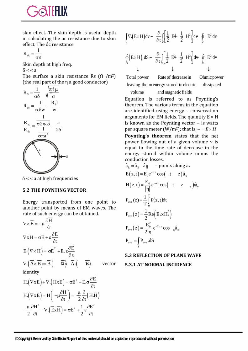
δ < < a at high frequencies 5.2 THE POYNTING VECTOR Energy transported from one point to another point by means of EM waves. The rate of such energy can be obtained.
HEt
∂∇× =−µ
∂
ExH Et
∂∇ = σ + ε
∂
( ) 2 EE. H E E.t
∂∇× = σ + ε
∂
( ) ( ) ( ). A B B. A A. B∇ × = ∇× − ∇× vector
identity
( ) ( ) 2 EH. xE . HxE E E.t
∂∇ +∇ = σ + σ
∂
( ) ( )HH. xE H H.Ht 2 t
∂ µ ∂ ∇ = −µ = − ∂ ∂
( )2 2
2H 1 E. ExH E2 t 2 tµ ∂ ∂
− −∇ = σ + ε∂ ∂
( ) 2 2 2
V V V
1 1. E H dv E H dv E dvt 2 2∂ ∇ × =− ε + µ − σ ∂ ∫ ∫ ∫
( ) 2 2 2
S V V
1 1E H .dS E H dv E dvt 2 2
Total power Rateof decreasein Ohmic powerleaving the energy stored in electric dissipated
volume and magnetic fields
∂ × =− ε + µ − σ ∂
↓ ↓ ↓
=
∫ ∫ ∫
Equation is referred to as Poynting’s theorem. The various terms in the equation are identified using energy – conservation arguments for EM fields. The quantity E × H is known as the Poynting vector − is watts per square meter (W/m2); that is, − HE×= Poynting’s theorem states that the net power flowing out of a given volume v is equal to the time rate of decrease in the energy stored within volume minus the conduction losses.
k E Hˆ ˆ ˆa a a= × − points along ak
( ) ( )z0 xˆE z, t E e cos t z a−α= ω −β
( ) ( )z0y
E ˆH z, t e cos t z a−αη= ω −β −θ
η
( )∫=T
0ave dtt,zP
T1)z(P
( ) ( )*s save
1P z Re E xH2
=
( )2
2 z0ave z
E ˆP z e cos a2
− αη= θ
η
∫=S
aveave dS.PP
5.3 REFLECTION OF PLANE WAVE
5.3.1 AT NORMAL INCIDENCE
a
© Copyright Reserved by Gateflix.in No part of this material should be copied or reproduced without permission

Incident wave (Ei, Hi) is traveling along + az in medium 1. If we suppress the time factor ejwt and assume that
( ) 1zis io xˆE z E e a−γ=
( ) 1z ziois io y y
1
Eˆ ˆH z H e a e a−γ −γ= =η
Reflected wave ( ) x
zrors aeEzE 1γ=
( ) ( )1 1z zrors ro y y
1
Eˆ ˆH z H e a e aγ −γ= − = −η
Transmitted wave ( ) 1z
ts to xˆE z E e a−γ=
( ) ( )1 1z ztots to y y
1
Eˆ ˆH z H e a e aγ −γ= − = −η
The interface at z = 0, 2 tan the boundary conditions E11 = Eat , H11 = H2t
1 i r 1 i rE E E ,H H H= + = +
2 t 2 tE E ,H H= =
( ) ( ) ( )i r t io ro toE 0 E 0 E 0 E E E+ = → + =
( ) ( ) ( ) ( ) toi r t io ro
1 2
E1H 0 H 0 H 0 E E+ = → − =η η
2 1ro io
2 1
E Eη −η=η +η
2to io
2 1
2E Eη=η +η
12
12
io
ro
EE
η+ηη−η
==Γ
Reflection coefficient
12
2
io
to 2EE
η+ηη
==τ
Transmission coefficient 1. 1 + Γ = τ2. Both Γ and τ are dimensionless and
may be complex.3. 0 ≤ | Γ | ≤ 1
Case A If Ez = 0 The totally reflected wave combines with the incident wave to form a standing wave.
1111io
ro j,0,0,1EE
β=γ=α=σ−==Γ
1 io 1z xˆE 2E sin sin t a= β ω
io1 1z y
1
2E ˆH cos cos ta= β ωη
Case B If η1, Γ < 0. For this case, the locations of |E1| maximum are given by eq. whereas those of |E1| minimum are given by eq. All theses are illustrated in Figure. 1. |H1| minimum occurs whenever there is
|E1| maximum which versa.2. The transmitted wave ( not shown in
Figure) in medium 2 is a purelytraveling wave and consequently thereare no maxima or minima in this region.The ratio of |E1|max (or |E1| min (or|H1|max to |H1| min ) is called the standingwave ratio s; that is,
1 1max max
1 1min min
E H 1s
E H 1+ Γ
= = =− Γ
1s1s
+−
=Γ
Since ,1≤Γ it follows that 1 ≤ s ≤ ∞. The standing – wave ratio is dimensionless and it is customarily expressed in decibels (dB) as S in dB = 20 log10 s
5.3.2 AT OBLIQUE INCIDENCE
© Copyright Reserved by Gateflix.in No part of this material should be copied or reproduced without permission

η×
=×ωµ
=EaEk1H k t
t i 2 1 1
i t 1 2 2
sin k usin k u
θ µ ε= = =
θ µ ε
1 i 2 tn sin n sinθ = θ
where 1 1 1 1n c c / u= µ ε = and
2222 u/ccn =εµ= are the refractive indices of the media. A. Parallel Polarization
i1t2
i1t2
io
ro|| coscos
coscosEE
θη+θηθη−θη
==Γ
i1t2
i2
io
to|| coscos
cos2EE
θη+θηθη
==τ
2t tcos 1 sinθ = − θ
( )2 22 1 t1 u u sin= − − θ
θθ
τ=Γ+i
t|||| cos
cos1
( )2
21
2112||B
2
/1/1sinεε−
εµεµ−=θ
2 2B|| B||
1 2 1 2
1sin sin1
εθ = → θ =
+ ε ε ε + ε
1
2
1
2||B n
ntan =εε
=θ
B. Perpendicular Polarization
t1i2
t1i2
io
ro
coscoscoscos
EE
θη+θηθη−θη
==Γ⊥
ioro EE ⊥Γ=
t1i2
i2
io
to
coscoscos2
EE
θη+θηθη
==τ⊥
to ioE E⊥= τ
1 ⊥ ⊥+Γ = τ
( )
2 1 2 2 1B 2
1 2
1 /sin1 /⊥
−µ ε µ εθ =
− µ µ
2B||
1 2
sin µθ =
µ +µ
1
2Btan
µµ
=θ ⊥
io||to EE =τ=
© Copyright Reserved by Gateflix.in No part of this material should be copied or reproduced without permission

Q.1 Two coaxial cables 1 and 2 are filled with different dielectric constants
r1ε and r2ε respectively. The ratio of the wavelengths in the two cables, ( )1 2λ / λ s
a) r1 r2/ε ε b) r2 r1/ε ε
c) r1 r2/ε ε d) r2 r1/ε ε [GATE – 2000]
Q.2 A uniform plane wave in air impinges at 450 angle on a lossless dielectric material with dielectric constantϵr. The transmitted wave propagates in a 30 direction with respect to the normal. The value of
r∈ isa) 1.5 b) 1.5
c) 2 d) 2 [GATE – 2000]
Q.3 A material has conductivity of 10−2 mho/m and a relative permittivity of 4. The frequency at which the conduction current in the medium is equal to the displacement current is a) 45 MHz b) 90 MHzc) 450 MHz d) 9000 MHz
[GATE – 2001]
Q.4 If a plane electromagnetic wave satisfies the equation
2 22x x
2 2
E Ec ,z t
∂ ∂=
∂ ∂the wave
propagates in the a) x-directionb) z-directionc) y- directiond) xy plane at an angle of 45
between the x and z directions[GATE – 2001]
Q.5 Distilled water at 250C is characterized by 41.7 10−σ = × mho/m and 078∈= ∈ at a frequency of 3 GHz. Its loss tangent tan δ is a) -51.3×10 b) 31.3 10−×c) 41.7 10 / 78−× d) 4
01.7 10 / (78 )−× ∈9( 10 / (36π)F / m)−∈=
[GATE – 2002]
Q.6 A plane wave is characterized by( )j /2 j t jkzˆ ˆE 0.5x ye eπ ω −= +
This wave isa) linearly polarizedb) circularly polarizedc) elliptically polarizedd) unpolarized
[GATE – 2002]
Q.7 If the electric field intensity associated with uniform plane electromagnetic wave travelling in a perfect dielectric medium is given by 7E(z, t) 10cos(2 10 t 0.1 / z)= π× − π volt/m, the velocity of the travelling wave is a) 83.00 10 m / sec× b) 82.00 10 m / sec×c) 76.28 10 m / sec× d) 72.00 10 m / sec×
[GATE – 2003]
Q.8 A uniform plane wave travelling in air is incident on the plane boundary between air and another dielectric medium with r 4.ε = The reflection coefficient for the normal incidence, is a) zero b) 00.5 180∠c) 00.333 0∠ d) 00.333 180∠
[GATE – 2003]
Q.9 Medium 1 has the electrical permittivity 1 01.5ε = ε farad/m and occupies the region to the left of x 0= plane. Medium 2 has the
GATE QUESTIONS
© Copyright Reserved by Gateflix.in No part of this material should be copied or reproduced without permission

electrical permittivity 2 02.5ε = ε farad/m and occupies the region to the right of x 0= plane. If 1E in medium 1 is 1 x y zE (2u 3u 1u )= − + volt/m, then 2E in medium 2 is
a) x y z( u 7.5u 2.2.0 )vu / m5 olt− + b) x y z( u 7.5u 2.2.0 )vu / m5 olt− +
c) x y z(1.2u 3.0u 1.0u )− + volt/m d) x y z(1.2u 2.0u 0.6u )− + volt/m [GATE – 2003]
Q.10 The depth of penetration of
electromagnetic wave in a medium having conductivity σ at a frequency of 1 MHz will be penetration at a frequency of 4 MHz will be
a) 6.25 cm b) 12.50 cm c) 50.00 cm d) 100.00cm
[GATE – 2003]
Q.11 If ( ) jkz j tx yˆ ˆE a ja e − ω= +
and
( ) jkz j tx y
k ˆ ˆH a ja e − ω = + ωµ
, the time
averaged pointing vector is
a) null vector b) zk a
ωµ
c) z2k a
ωµ d) z
k a2
ωµ
[GATE – 2004 ]
Q.12 The magnetic field intensity vector of plane wave is given by. ( ) ( ) yˆH x, t 10sin 50000t 0.004x 30 a= + +
where ˆya denotes the unit vector in y direction. The wave is propagating with a phase velocity. a) 45 10 m / s× b) 83 10 m / s× c) 71.25 10 m / s× d) 63 10 m / s×
[GATE – 2005]
Q.13 When a plane wave travelling in free-space is incident normally on a
medium having r 4.0,ε = the fraction of power transmitted into the medium is given by
a) 8/9 b) 1/2 c) 1/3 d) 5/6
[GATE – 2006]
Q.14 A medium is divided into regions I and II abour X = 0 plane, as shown in the figure below, an electromagnetic wave with electric field x y zˆ ˆ ˆE 4a 3a 5a= + + is incident normally on the interface from region-I. The electric field 2E in region – II at the interface is
a) 2 1E E=
b) x y zˆ ˆ ˆ4a 0.75a 1.25a+ −
c) x y zˆ ˆ ˆ3a 3a 5a+ +
d) x y zˆ ˆ ˆ3a 3a 5a− + + [GATE – 2006]
Q.15 A medium of relative permittivity
r2 2ε = forms an interface with free-space. A point source of electromagnetic energy is located in the medium at a depth of 1 meter from the interface. Due to the total internal reflection, the transmitted beam has a circular cross-section over the interface. The area of the beam cross – section at the interface is given by
a) 22πm b) 2 2π m
c) 2π / 2m d) 2πm [GATE – 2006]
© Copyright Reserved by Gateflix.in No part of this material should be copied or reproduced without permission
Q.16 The electric field of an electromagnetic wave propagating in the positive z-direction is given by.
( )x yˆ ˆE a sin t z a sin t z2π = ω −β + ω −β +
The wave is a) linearly polarized in the z-
directionb) elliptically polarizedc) left-hand circularly polarizedd) right-hand circularly polarized
[GATE – 2006]
Q.17 A plane wave of wavelength λ is travelling in a direction making an angle 300 with positive x-axis and 900 with positive y-axis The E
field of the plane wave can be represented as (E0 is constant)
a) 3j t x z
0ˆE yE e
− − =
π πωλ λ
b)
3j t x z
0ˆE yE e
− − =
π πωλ λ
c)
3j t x z
0ˆE yE e
+ + =
π πωλ λ
d)
3j t x z
0ˆE yE e
− + =
π πωλ λ
[GATE – 2007]
Q.18 A Right Circularly Polarized (RCP) plane wave is incident at an angle of 60 to the normal, on an air-dielectric interface. If the reflected wave is linearly polarized, the relative dielectric constant r2ε is
a) 2 b) 3c) 2 d) 3
[GATE – 2007]
Q.19 The H
field (in A/m) of a plane wave propagating in free space is given by
( )0 0
5 3 5ˆ ˆH x cos t z y sin t z2π = ω −β + ω −β + η η
The time average power flow density in watts is
a) 0
100η b)
0
100η
c) 2050η d)
0
50η
[GATE – 2007]
Q.20 A uniform plane wave in the free space is normally incident on an infinitely thick dielectric slab (dielectric constant 9=rε ).The magnitude of the reflection coefficient is. a) 0 b) 0.3c) 0.5 d) 0.8
[GATE – 2008]
Q.21 A plane wave having the electric field component
( )8i xˆE 24cos 3x10 t y a V / m= +β
and travelling in free space is incident normally on a lossless medium with
0µ = µ and 09=ε ε which occupies the region y 0.≥ The reflected magnetic field component is given by. a) ( )81 ˆcos 3 10
10+ xx t y a
π A/m
b) ( )81 ˆcos 3 1020
+ xx t y aπ
A/m
c) ( )81 ˆcos 3 1020
− + xx t y aπ
A/m
d) ( )81 ˆcos 3 1010
− + xx t y aπ
A/m
[GATE – 2010]
Q.22 The electric field component of a time harmonic plane EM wave
© Copyright Reserved by Gateflix.in No part of this material should be copied or reproduced without permission

travelling in a nonmagnetic lossless dielectric medium has an amplitude of 1 V/m. If the relative permittivity of the medium is 4, the magnitude of the time average power density vector (in W/m2) is
a) 130π
b) 160π
c) 1120π
d) 1240π
[GATE – 2010]
Q.23 Consider the following statement regarding the complex Poynting vector P
for the power radiated by a point source in an infinite homogenous and lossless medium. Re P
denotes the real part of P
, S denotes a spherical surface whose centre is at the point source, and n⏞ denotes the unit surface normal on S. Which of the following statement is TRUE? a) Re P
remains constant at any radial distance from the source
b) Re P
increases with increasing radial distance from the source
c) ( )S
ˆRe P n∫∫
dS remains constant at
any radial constant at any radialdistance from the source
d) ( )S
ˆRe P n∫∫
dS decreases with
increasing radial distance fromthe source
[GATE – 2011]
Q.24 A current sheet yˆJ 10u=
A/m lies on the dielectric interface x = 0 between two dielectric media with
r1 r1ε 1,μ 1= = in Region-1 (x < 0) and
r2 r2ε 2,μ 2= = in Region-1 at x=0 is
1 x yˆ ˆH 3u 30u= +
A/m, the magnetic field in Region – 2 at x = 0+ is
a) 2 x y zˆ ˆ ˆH 1.5u 30u 10u A/m= + −
b) 2 x y zˆ ˆ ˆH 3u 30u 10u A/m= + −
c) 2 x yˆ ˆH 1.5u 40u A/m= +
d) 2 x y zˆ ˆ ˆH 3u 30u 10u A/m= + +
[GATE – 2011]
Q.25 A plane wave propagating in air with ( ) t 3x 4y
x y zˆ ˆ ˆE 8a 6a 5a eω + += − +
isincident on a perfectly conducting slab positioned at x 0.≤ the E
field of the reflected waves is a) ( ) t 3x 4y
x y zˆ ˆ ˆ8a 6a 5a e V / mω + +− − −
b) ( ) t 3x 4yx y zˆ ˆ ˆ8a 6a 5a e V / mω + +− + −
c) ( ) t 3x 4yx y zˆ ˆ ˆ8a 6a 5a e V / mω − −− − −
[GATE – 2012]
Q.26 The electric field of a uniform plane electromagnetic wave in free space, along the positive x direction, is given by j25x
y zˆ ˆE 10(a ja )e−= +
. The frequency and polarization of the wave. Respectively, are a) 1.2 GHz and left circularb) 4 Hz and left circularc) 1.2 GHz and right circulard) 4 GHz and right circular
[GATE – 2012]
Q.27 A coaxial-cable with an inner diameter of 1 mm and outer diameter of 2.4 mm is filled with a dielectric of relative permittivity 10.89. Given
9
7
0 0
10 F10 H 36πμ 4π ,ε ,m m
−
−
= × = the
characteristic impedance of the cable as
© Copyright Reserved by Gateflix.in No part of this material should be copied or reproduced without permission

a) 330Ω b) 100Ωc) 143.3Ω d) 43.4Ω
[GATE – 2012]
Statement for Linked Answer Questions 28 and 29 A monochromatic plane wave of wavelength 600 mλ µ= is propagating in the
direction as shown in the figure below. iE
, rE
and tE
denote incident, reflected, and transmitted electric field vectors associated with the wave
Q.28 The expression for rE
is
a) ( )( )4π 10 x z
j0 3 2
x zE ˆ ˆa a e V / m
20.23
× −−
+
b) 4π 10 zj0 3
x zE ˆ ˆ(a a )e V / m
2
×
− +
c) ( )( )4π 10 x z
j0 3x z
E ˆ ˆ0.44 a a e V / m2
× −−
+
d) ( )( )4π 10 x z
j0 3x z
E ˆ ˆa a e V / m2
× −−
+
[GATE – 2013]
Q.29 The angle of incidence θi and the expression for Ei are
a) ( )( )4π 10 x z
j0 3 2
x z60 and E ˆ ˆa a e 2
V/m× +
−−
b) ( )4π 10 zj0 3
x zE ˆ ˆ45°and a a e V / m
2
×−
+
c) ( )4π 10j
0 3 2x z
(x z)E ˆ ˆ45°and a a e V / m2
×−
+
−
d) ( )4π 10j0 3
x z
zE ˆ ˆa a60 an ed V/m2
×−
−
[GATE – 2013]
Q.30 If the electric field of a plane wave is ( ) x cos( t kz 3o ) sE Z, t 3 ω − + °= −
( )( kz 45 ) mV / m ,− + ° the polarization state of the plane wave is a) left elliptical b) left circularc) right elliptical d) right circular
[GATE – 2014-2]
Q.31 Assume that a plane wave in air with an electric field
yE 10cos( t 3x 3 )a V / m= − −
ω z is incident on a non-magnetic dielectric slab of relative permittivity 3 which covers the region. Z > 0 The angle of transmission in the dielectric slab is _________.degrees.
[GATE – 2014-3]
Q.32 The electric field component of a plane wave travelling in a lossless dielectric medium is given by
8y
zˆE(z, t) a 2cos cos 10 t V / m2
= −
. The wavelength (in m) for the wave is __________.
[GATE – 2015-1]
Q.33 Consider a uniform plane wave with amplitude 0(E ) of 10V / m and 1.1GHz frequency travelling in air, and incident normally on a dielectric medium with complex relative permittivity ( )rε and permeability ( )rμ as shown in the figure.
© Copyright Reserved by Gateflix.in No part of this material should be copied or reproduced without permission

The magnitude of the transmitted electric field component (in V/m) after it has travelled a distance of 10 cm inside the dielectric region is _______________.
[GATE – 2015-1]
Q.34 The electric field intensity of a plane wave traveling in free space is give by the following expression ( ) ( )y 0a 24πcos(ωt kE x, t / mx) V−=
In this field, consider a square area 10cm x 10 cm on a plane x + y = 1. The total time-averaged power (in mW) passing through the square area is______
[GATE – 2015-1]
Q.35 The electric field of a uniform plane electromagnetic wave is
7yxE (a j4a )exp[ j(2 10 t 0.2z)]= + π× −
The polarization of the wave is a) Right handed circularb) Right handed ellipticalc) Left handed circulard) Left handed elliptical
[GATE – 2015-2]
Q.36 The electric field of a plane wave propagating in a lossless non-magnetic medium is given by the following expression
9x
9y
ˆE(z, t) a 5cos(2 10 t z)
a 3cos(2 10 t z )2
= π× +βπ
+ π× +β −
The type of the polarization is a) Right Hand Circular.b) Left Hand Ellipticalc) Right Hand Elliptical d) Linear
[GATE – 2015-2]
Q.37 The electric field of a uniform plane wave travelling along the negative z direction is given by the following equation: ( )i jkz
w x y 0ˆ ˆE a ja E e= +
This wave is incident upon a receiving antenna placed at the origin and whose radiated electric field towards the incident wave is given by the following equation:
( ) jkrx ya I
1E = a +2a E er
The polarization of the incident wave, the polarization of the antenna and losses due to the polarization mismatch are, respectively, a) Linear, Circular (clockwise),-5dBb) Circular (clockwise), Linear,-5dBc) Circular (clockwise), Linear,-3dBd) Circular (anti clockwise),
Linear,-3dB[GATE – 2016-1]
Q.38 Let the electric field vector of a plane electromagnetic wave propagating in a homogenous medium be expressed as
j(ωt βz)xˆ ,E xE e− −= where the
propagation constant β is a function of the angular frequency𝜔𝜔. Assume that β (ω) and xE are known and are real. From the information available, which one of the following CANNOT be determined? a) The type of polarization of the
wave.b) The group velocity of the wave.c) The phase velocity of the wave.d) The power flux through the z = 0
plane.[GATE – 2016-2]
Q.39 A positive charge q is placed at x= 0 between two infinite metal plates placed at x=-d and at x=+d respectively. The metal plates lie in the yz plane.
© Copyright Reserved by Gateflix.in No part of this material should be copied or reproduced without permission
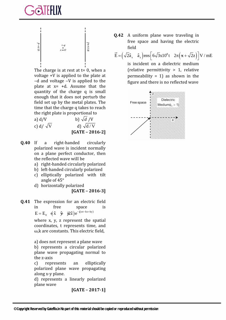
The charge is at rest at t= 0, when a voltage +V is applied to the plate at ‒d and voltage ‒V is applied to the plate at x= +d. Assume that the quantity of the charge q is small enough that it does not perturb the field set up by the metal plates. The time that the charge q takes to reach the right plate is proportional to a) d/V b) d /Vc) d/ V d) d / V
[GATE – 2016-2]
Q.40 If a right-handed circularly polarized wave is incident normally on a plane perfect conductor, then the reflected wave wiII be a) right-handed circularly polarizedb) left-handed circularly polarizedc) elliptically polarized with tilt
angle of 45°d) horizontally polarized
[GATE – 2016-3]
Q.41 The expression for an electric field in free space is
( ) ( )j t kx ky0 ˆ ˆ ˆE E x y j2z e− ω − += = + +
where x, y, z represent the spatial coordinates, t represents time, and ω,k are constants. This electric field,
a) does not represent a plane waveb) represents a circular polarizedplane wave propagating normal to the z-axis c) represents an ellipticallypolarized plane wave propagating along x-y plane. d) represents a linearly polarizedplane wave
[GATE – 2017-1]
Q.42 A uniform plane wave traveling in free space and having the electric field
( ) ( )8x zˆ ˆE 2a a cos 6 3x10 t 2 x 2z V / mE = − − π +
is incident on a dielectric medium (relative permittivity > 1, relative permeability = 1) as shown in the figure and there is no reflected wave
© Copyright Reserved by Gateflix.in No part of this material should be copied or reproduced without permission

1 2 3 4 5 6 7 8 9 10 11 12 13 14 (b) (c) (a) (b) (a) (c) (b) (d) (c) (b) (a) (c) (a) (c) 15 16 17 18 19 20 21 22 23 24 25 26 27 28 (d) (c) (a) (d) (d) (c) (a) (c) (c) (a) (c) (a) * (a) 29 30 31 32 33 34 35 36 37 38 39 40 41 42 (c) (a) 30 8.8 0.1 53.3 (d) (b) (c) (d) (c) (b) (c) 2
ANSWER KEY:
© Copyright Reserved by Gateflix.in No part of this material should be copied or reproduced without permission
Q.1 (b)
11 1
1vµ
=∈
22 2
1vµ
=∈2
11
2
vv
∈=
∈v ηλ= n = frequency of operation v λ∝
21
12
λλ
∈∴ =
∈
Q.2 (c) sin 1sin
tr
i
θθ
=∈
0
0
sin 30 1sin 45 r
=∈
1/ 2 11/ 2 r
⇒ =∈
2rε⇒ =
Q.3 (a) E j Eσ ω= ∈
02 rfσ π= ∈ ∈
02 r
f σπ
⇒ =×∈ ∈
9 29 10 2 104
−× × ×=
6F 45 10 45MHz= × =
Q.4 (b)
Q.5 (a)
tan σδω
=∈
4
90
1.7 102 3 10 78π
−×=
× × × ∈40.13 10−= ×
51.3 10−= ×
Q.6 (c) ( )j t kz
x ˆE 0.5e x−=
ω
( )j t kzy ˆE 1e y−=
ω
x 2
y
E 10.5e 902E
−= = ∠
π
Since x
y
E 1E
≠
,so elliptically
polarised.
Q.7 (b) 72 10ω π= ×
0.1β π= Comparing with Acos ( )t zω β−
72 100.1
v ω πβ π
×= =
82 10 /m s= ×
Q.8 (d) 2 1
1z
η ηη η
−Γ =
+
0 0
0 r 0
0 0
0 r 0
μ μ
μ μ
−=
+
rr
r
1 1
1 14
−
= =+
=
01/ 2 1 0.333 1803 / 2 3− −
= = ⇒ ∠
Q.9 (c) 1 2 3 1x y zE u u u= − +
EXPLANATIONS
© Copyright Reserved by Gateflix.in No part of this material should be copied or reproduced without permission

1 23t y z tE u u E= − + = ( 0 )x plane= 1 2n xE u= 1 2n nD D E= =∈ 1 1 2 2n nE E⇒ ∈ =∈ 0 0 21.5 .2 2.5 .x nu E= ∈ = ∈
23 1.2
2.5n x xE u u= =
2 2 2t nE E E= + 2 3 1.2y z xE u u u= − + + Q.10 (b)
1f
δ ∝
2 1
1 2
ff
δδ
=
21MHzδ 25cm4MHz
= ×
2 12.5cmδ = Q.11 (a) avg
1P Re ExH2
=
( ) jkz ej tx y
1 ˆ ˆRe a ja e2
− ω +
( ) jkz j tx y
k ˆ ˆx a ja e− −+ ω
ωµ [ ]avg
kP 0 02ωμ
= =
21 11 1 1 0
1j
j
= + = − = −
Q.12 (c) 50,000ω = β = - 0.004
v ωρβ
=
4
3
5 104 10−
×=− ×
71.25 10 /m s= − × Q.13 (a) 2
1 (1 ) iP P= −Γ
2 1
2 1
η ηη η
−Γ =
+
0 0
0 0
0 0
0 0
r
r
µ µ
µ µ
−∈ ∈ ∈
=+
∈ ∈ ∈
1 1 121 312
− −Γ = =
+
2 1 81 19 9
T = −Γ = − =
.t iP T P∴ =
89
t
i
PP=
Q.14 (c) 1t y z 2tˆ ˆE 3a 5a E= + =
1 2n nD D=
2
kldlsindHR
α=
x2n x
ˆ3x4a ˆE 3a4
= =
2 2 2t nE E E= + y z xˆ ˆ ˆ3a 5a 3a= + + Q.15 (d) 1 1sin
2r
θ = =∈
0454πθ = =
BD = AB = 1m Area 2 2 2r BD mπ π π= = × = Q.16 (c) Q.17 (a) Q.18 (d)
© Copyright Reserved by Gateflix.in No part of this material should be copied or reproduced without permission

2
1
tan rB
r
εθε
=
0 2tan 601rε=
23 rε=
2 3rε =
Q.19 (d) For free space,
2
00
,2EP E Hηη
= =
2 20 0
02 2H HP η ηη
= =
2 2
0 0
1 10(5 3) (5)Hη η
= + =
02
0
1002
P ηη
= ×
0
50Pη
= Watts
Q.20 (c) Dielectric constant of free space,
1 1r∈ = dielectric constant of dielectric slab, 2 9r∈ = Magnitude of reflection coefficient,
1 2
1 2
1 3 2 0.51 3 4
r r
r r
ε ερ
ε ε− −
= = = =++
Q.21 (a)
( )81 zE 24cos 3 10 t βy a= × −
The wave is travelling in + y direction
( )i 1y1 ˆH a xE=η
( )8x
24cos ˆ3x10 t y a120
= −βπ
( )8x
1 ˆcos 3x10 t y a5
= −βπ
0 0
1 21 2
1 2 0 0
1 2
r
i
HH
µ µη ηη η µ µ
−∈ ∈−
= =+
+∈ ∈
2 1
2 1
9 19 1
∈ − ∈ −= =
∈ + ∈ +
3 1 2 13 1 4 2−
= = =+
Therefore, reflected magnetic field component,
( )8r x
1 ˆH cos 3x10 t y a5
= −βπ
Which indicates that the reflected wave is travelling in –y direction.
Q.22 (c) Magnitude of the time-average power density vector,
2
2avEPη
=
Where, /η µ= ∈
0 0
0
1204 2 2µ η πη = = =∈
221 1 /
120 12022
avP W mπ π
= =
Q.23 (c)
Q.24 (a) For magnetic field boundary relations are
1 2B Bη η=
and s nt1 t2H H J xa− = −
1 2x xB B⇒ =∴ (x is normal component)
1 1 2 2x xH Hµ µ= ⇒ 1 × 3 = 2 × Hx2
21.5xH =
1 2t yt xˆ ˆxH 10u uH⇒ − = −
zˆ10u= +
t 2 t1 zˆH H 10u= −
© Copyright Reserved by Gateflix.in No part of this material should be copied or reproduced without permission
t 2 z zˆ ˆH 30u 100u= − Q.25 (c)
( ) ( )j t 3x 4yx y zˆ ˆ ˆE 8a 6a 5a e ω + −= + +
v/m
Since perfect conductor will reflect wave totally. Let reflected wave is
REur
. Tangential component of incident wave is
t y zˆ ˆE 6a 5a= +
Since at the boundary net tangential field will be zero. For this tangential component of reflected wave ( )trE
and tangential component of incident wave must cancel out each other, for this
tr y zˆ ˆE 6a 5a= − −
Reflected wave will have normal component such that it will cancel out the normal component of incident wave so it will be xˆ8a− Also the direction of propagation will be in –x direction. So
( ) ( )j t 3x 4yx y zˆ ˆ ˆE 8a 6a 5a e ω − −= − − −
v/m. Q.26 (a)
Out of phase by 900 and equal amplitude the wave is left circularly polarized check the trace of E with the time
sinya tω= cosza tω=
Q.27 (*)
Characteristic impedance of the co-axial cable is given by
0138 log
r
DZd
=∈
138 2.4log 15.89110.89
= = Ω
Q.28 (a) Q.29 (c)
Electric field boundary condition Electric lies in the x – z plane the
plane of incidence in the case of parallel poarization.
1 2sin sinr i r tξ θ ξ θ= 01sin 4.5 sin(19.2 )iθ =
sin 2.12 0.3289iθ = × sin 0.697iθ =
0.697iθ =
( )1sin 0.697iθ−=
44.2iθ = 045iθ =
Incidence electric field ( )
( )
ji io i x i z
i i
ˆ ˆE E cos a sin a e
xsin zcos
β= θ − θ
θ + θ
( )0 cos 45= Ei E
$ $( )410 1 ( )
3 212
j x zx zi oE E a a e
π− ×+
= −
$ $( )410 ( )
0 3 2 / .2
j x z
x ziEE a a e V m
π× +−
= −
Q.30 (a)
( ) ( )1
x y
E z t 3cos cot-kz 30a -4 -sin( t kz 45 )a
= + °
ω − + °
x E =3cos ( t kz 30 )ω − + °
yE 4cos( t kz 45 )=− ω − + ° At xz 0 E 3cos( t 30 )= = ω + ° . yE 4sin( t 45 )=− ω + °
x y|E | |E | so≠ → Elliptical polarization
Q=30° —135°=-105° ∴left hand elliptical (LEP) Q.31 (30) yGiven E 10 cos ( t 3x 3z)a= ω − −
Jβ( x cosθ y cosθ z cosθ )x y ze0E E − + +=
So, βx= β cos θx = 3 yy co 0β s= β θ =
zz co 3β s= β θ =
2 2 2 2x y zβ β β β+ + =
2 β3 β 39 1⇒ =+ =
© Copyright Reserved by Gateflix.in No part of this material should be copied or reproduced without permission
z zcos 3 sβ coθ = ⇒ θ
z i3 61.28
13= ⇒ θ = = θ
i 2
i 1
sin θ Esinθ E
=
tt
sin 61.28 3 0.8769 sin θsin θ 1 3
⇒ = ⇒ =
o
t tθ 30.4 θ 30= ⇒ ; Q.32 (8.885)
8y
zE(z, t) 2cos(10 t )a2
= −
2πλ 2π 2β
= =
λ 8.885m= Q.33 (0.1)
( ) ( )
r1
r1
2
21
Dieletric(σ 0)air
μ 1 j2η 120π
1 j2E 10V / m
η 120π
== −
== −
==
Ω
Ω
21η η= So, 2 1 mE /E 10V==
3E Electric field in the dieletric after travelling10cm
→
γz3 2E E e−= →
( )r α jβ jωμ σ jω= + = + ∈
0 0 r rα jβ ω μ μ+ =
0 0α jβ jω μ (1 j2)+ = −
0 0 0 0jω μ 2ω μ= + 9
0 0 8
2 2π 1.1 10α 2ω μ 46.073 10
× × ×= = =
×
z = 10 cm
210 10 46.07 4.63E 10e 10e 0.1
−− × × −= = = Q.34 (53.3)
( ) ( )y 0a 24πcos(ωt kE x x, t / m) V= −
20
avg xE1P a
2 η=
2
x1 (24π) a2 120π
=
= 7.53ax
Power (P) = avs
gP .ds∫
x+ y= 1
x ya aunit vector normal
2+
→
To the surface
xx
s
2
aP 7.53a . dydz2 P 53.3mW
7.53 10 10 102
−
==
= × × ×
∫
3P 53.3 10 W−×= Q.35 (d)
7j(2 ?10 t 0.2z)x yE (a 4ja )e π× −= +
72 10ω = π×
zE tcos ω= β 0.2=
y 4cos( sin tE )2π
= ω+ = − ω
So, it left hand elliptical polarization Q.36 (b)
x 5cos( zE t )= ω +β
yπE ωt βcos2
3 z= + −
π2
φ = −
But the wave is propagating along negative z-direction So, Left hand elliptical (LED).
Q.37 (c) Q.38 (d)
Option (a): The polarization is linear
Option (b): Vg = p
CV
© Copyright Reserved by Gateflix.in No part of this material should be copied or reproduced without permission

Option (c): Vp = ωβ
Option (D): It is not possible to find the intrinsic impedance of the medium. So it is not possible to find power flux.
Q.39 (c) Q.40 (b)
If incident wave is right handed polarized then the reflected wave is left handed polarized.
Q.41 (c) Given the direction of propagation is x yˆ ˆa a−
The orientation of E field is x y zˆ ˆ ˆa a j2a+ +
The dot product between above two is 1 – 1 + 0 = 1
It is a plane wave We observed that
x y x y zˆ ˆ ˆ ˆ ˆP a a ,a a and j2a= − + are
normal to each other
So electric field can be resolved into two normal component along x y zˆ ˆ ˆa a and j2a+
The magnitude are 2 and 2 and
2π
θ =
So elliptical polarization Q.42 2
( ) ( )( )811 zˆ ˆE 2a a cos 3 x10 t 2 x 2z V / m= − σ π − π +
The wave is parallel to the x, z plane
Since, there is no reflection,
Angle of incidence in Brewster angle is
1 12i B 2
1
i
2
2
tan tan
tan 2
22
− −εθ = θ = = ε
ε
θ =
ε =
ε =
© Copyright Reserved by Gateflix.in No part of this material should be copied or reproduced without permission

6.1 INTRODUCTION
Transmission lines are commonly used in power distribution (at low frequencies) and in communications (at high frequencies). There are various kinds of transmission lines such as the twisted–pair and coaxial cables.
1) The line parameters R, L, G and notdiscrete or lumped but distributed asshown in figure. By this we mean thatthe parameters are uniformlydistributed along the entire length ofthe line.
Parameters Coaxial Line Two – Wire Line
Planer Line
R ( Ω /m)
( )c
1 1 12 a b
a,c b
− πδσ δ << − a
a1
c
<<δδσπ
( )tw
2
c
<<δδσ
L (H/m) abIn
2πµ 1 dcosh
2a−µ
π wdµ
G(S/m)
abIn
a2π1 dcosh
2a−
πσ
dwσ
C (F/m)
abIn
2πε1 dcosh
2a−
πε
( )dwdw
>>
ε
2) For each line, the conductor arecharacterized by 0ccc ,, ε=εµσ , and the homogeneous dielectric separating theconductor is characterized by εµσ ,, .
3) G ≠ 1/R; R is the resistance per unitlength of the conductor comprising theline and G is the conductance per unitlength of the conductor comprising theline and G is the conductance per unitlength due to the dielectric mediumseparating the conductors.
4) The value of L shown in Table is theexternal inductance per unit length;that is, L = Lext. The effects ofinternal inductance Lin ( = R/ω) arenegliable as high frequencies atwhich most communication systemsoperate.
5) For each line,
LC = µε andεσ
=CG
6.2 TRANSMISSION LINE EQUATIONS
∫ ∫=−= dI.HI,dI.EVBy KVL to the circuit
( ) ( ) ( ) ( )t,zzVt
t,zIzLt,zIzRt,zV ∆++∂
∂∆+∆=
( ) ( ) ( ) ( )t
t,zILt,zRIz
t,zVt,zzV∂
∂+=
∆−∆+
( ) ( ) ( )t
t,zILt,zRIz
t,zV∂
∂+=
∂∂
−
By KCL to the node of circuit ( ) ( )I z, t I z z, t I= +∆ +∆
( ) ( ) ( )V z z, tI z z, t G z V z z, t C z
t∂ +∆
= +∆ + ∆ +∆ + ∆∂
( ) ( )I z z, t I z, tz
+∆ −∆
( ) ( )V z z, tGV z z, t C
t∂ +∆
= +∆ +∂
( ) ( ) ( )I z, t V z, tGV z, t C
z t∂ ∂
− = +∂ ∂
series R and L
shunt G and C
6 TRANSMISSION LINE
© Copyright Reserved by Gateflix.in No part of this material should be copied or reproduced without permission

( ) ( ) j tsV z, t Re V z e ω =
( ) ( ) j tsI z, t Re I z e ω =
( )ss
dV R j L Idz
− = + ω
( )ss
dI G j C Vdz
− = + ω
( )( )2
ss2
d V R j L G j C Vdz
= + ω + ω
22s
s2
d V V 0dz
− γ =
( )( )CjGLjRj ω+ω+=β+α=γ2
2ss2
d I I 0dz
− γ =
2πλ =
β
u fω= = λβ 2 2 f
fπ π ω
β = = =λ λ µ2π ω
β = =λ µ
( ) z zs 0 0V z V e V e
z z
+ −γ − γ= +
→+ − ←z z
s 0 0I (z) I e I ez z
+ −γ − γ= +→+ − ←
The characteristic impedance Z0 of the line is the ratio of positively travelling voltage wave to current wave at any point on the line.
CjGLjR
IV
IV
Z0
0
0
00 ω+
γ=
γω+
=−== −
−
+
+
0 0 0R j LZ R jXG j C+ ω
= = ++ ω
A. Lossless Line (R = 0 = G) A transmission line is said to be lossless if the conductors of the line are perfect ( σc ≈ ∞) and the dielectric medium separating them is lossless ( σ ≈ 0). R = 0 = G
0,α = j j LCγ = β= ω
1u fLC
ω= = = λβ
0 0 0LX 0, Z RC
= = =
B. Distortionless Line (R /L = G/C) A distortionless line is one which the attenuation constant α is frequency independent while the phase constant β is linearly dependent on frequency. R GL C=
j L j CRG 1 1R Gω ω γ = + +
j CRG 1 jGω = + =α+ β
RG LCα = β =ω
( )( )0
R 1 j L / R R LZ ,G 1 j C / G G C
+ ω= = =
+ ω 0 0R jX= +
0 0R LR X 0G C
= = =
1u fLC
ω= = = λβ
A losses line is also a distortionless line, but a distortionless line is not necessarily lossless. Lines are desirable in power transmission, telephone lines are required to be distortionless.
Case Propagation Constant β+α=γ j
Characteristic Impedance Z0=R0 +jX0
General ( )( )CjGLjR ω+ω+CjGLjR
ω+ω+
- -
+ +
I(z, t) R z L z I(z + z, t)
V(z + z, t)G z C z
To load
To generator
V(z, t)
z + zzz
© Copyright Reserved by Gateflix.in No part of this material should be copied or reproduced without permission

Lossless LCj0 ω+ 0jCL+
Distortionless LCjRG ω+ 0jCL+
6.3 INPUT IMPEDANCE, SWR, & POWER
z = l
Zin
l’ = l -z
IL
VL
+
Zin
z = 0
zZ Ig o
+V0
Vg
+Zin
Zg
V0Vg
(a)
(b)z
0z
os eVeV)z(V γ−γ−+ +=
z
0
0z
0
0s e
ZV
eZV
)z(I γ−
γ−+
−=
V0 = V (z = 0), I0 = I( z = 0)
( )0 0 0 01V V Z I2
+ = +
( )0 0 0 01V V Z I2
− = −
gin0 g 0
in g in g
VZV V , IZ Z Z Z
= =+ +
( ) ( )L LV V z l , I I z l= = = =
( ) l0 L 0 L
1V V Z I e2
+ γ= +
( ) l0 0 0 0
1V V Z I e2
− −γ= −
( )0 0 0sin
s 0 0
Z V VV (z)ZI (z) V V
+ −
+ −
+= =
−
,cosh2
lee ll
γγγ
=+ −
lee ll
γγγ
sin2
=− −
l l
l l
sinh l e etan lcosh l e e
γ −γ
γ −γ
γ −γ = =
γ +
L 0in 0
0 L
Z Z tanh lZ ZZ Z tanh l
+ γ= + γ
(lossy)
L 0in 0
0 L
Z Z tanhZ ZZ jZ tan
+ β= + β
ll
(lossless)
The voltage reflection coefficient at any point on the line is the ratio of the magnitude of the reflected voltage wave to that of the incident wave.
l
0L l
0
V eV e
− γ
+ −γΓ =
L 0L
L 0
Z ZZ Z
−Γ =
+The current reflection coefficient at any point on the line is negative of the voltage reflection coefficient at that point. Voltage standing wave Ratio s (VSWR)
Lmax max
min min L
1V ISV I 1
+ Γ= = =
− Γ1 S< ≤ ∞
1 T 1− ≤ ≤ + max for min (zin) input impedance
maxin 0max
min
VZ sZI
= =
0minin min
max
ZVZI s
= =
Power Transmission at the l distance
[ ])(I)(VRe21P *
ssave ll=
( )2
0
2
0ave 1
Z2
VP Γ−=
+
Pt = Pi - Pr Special care of Transmission Line
A. Shorted Line (ZL = 0)
Lsc in Z 0 0Z Z jZ tan l== = β
L 1,sΓ =− = ∞
© Copyright Reserved by Gateflix.in No part of this material should be copied or reproduced without permission

B. Open – Circuited Line (ZL = ∞)
L
0oc in 0Z
ZZ lim Z jZ cot lj tan l→∞
= = = − ββ
∞==Γ s,1L 2
0ocsc ZZZ =
C. Matched Line (ZL = Z0) Zin = Z0 L 0,s 1Γ = = The incident power is fully absorbed by
the load. Thus maximum power transfer is possible when a transmission line is matched to the load.
The Smith chart is a graphical mean of obtaining line characteristics such as Γ, s, and Zin, It is constructed within a circle of unit radius and based on the formula for ΓL given above. For each r and x, it has two explicit circle (the constant s – circle). It is conveniently used in determining the location of a stub tuner and its length. It is also used
with the slotted line to determine the value of the unknown load impedance.
6.4 APPLICATIONS OF TRANSMISSION LINES A. Quarter – Wave Transformer (Matching)
l4λ
= or 24 2
π π π β = = λ l
When Z0 ≠ ZL the load is mismatched and a reflected wave exist on the line. However, for minimum power transfer, it is desired that the load be matched to the transmission line (Z0 = ZL) so there is no reflection the mateling is achieved by using shorted sections of transmission lines.
2
L 0 0in 0
0 L L
Z jZ tan / 2 ZZ ZZ jZ tan / 2 Z + π
= = + π
0in
0 L
ZZZ Z
=
L0'0 ZZZ =
If for example, a 120 - Ω load is to be matched to a 75 -Ω line, the quarter – wave transformer must have a characteristic impedance of ( )( )12075 ≈ 95 Ω.
Thus, the main disadvantage of the quarter
– wave transformer is that it is a narrow – band or frequency
– sensitive device B. Single – Stub Tuner (Matching)
A
ZL
d
Yo=1Zo
,s = 1
shorted stub
Y o,s=
8
The major drawback of using a quarter
– wave transformer as a line – matching
2 23 2
0
Zsc
Capacitive
Inductive
Z(a)
2 23 2
l0
Zoc
Capacitive
Inductive
(b)
© Copyright Reserved by Gateflix.in No part of this material should be copied or reproduced without permission

device is eliminated by using a single – stub tuner. The tuner consists of an open or shorted section of transmission line of length d connected in parallel with the main line at some distance l from the load as in Figure. Notice that the stub has the same characteristic impedance as the main line. It is difficult to use a series stub although it is theoretically feasible. An open – circuited stub radiates some energy are preferred.
As we intend that Zin = Z0, that is, Zin = 1 or yin = 1 at point A on the line, we first draw the locus y = 1 + jb ( r = 1 circle) on the Smith chart as shown in Figure 11.20. If a shunt stub of admittance ys = - jb is introduced at A, then
in sy 1 jb y 1 jb jb 1 j0= + + = + − = + We determine the length d of the stub by finding the distance from Psc (at which z’L = 0 + j0) to the required stub admittance ys. For the stub at A, we obtain d = dA as the distance from P to A’, where A’ corresponds to ys = -jb located on the periphery of the chart as in Figure 11.20. Similarly, we obtain d = dB as the distance from Psc to B’ (ys = jb). Thus we obtain d = dA and d = dB, corresponding to A and B, respectively, as shown in Figure 11.20. Note that dA + dB = λ/2 always. Since we have two possible shunted stubs, we normally choose to match the shorter stub or one at a position closer to the load. Instead of having a single stub shunted across the line, we may have two stubs. This is called double – stub matching and allows for the adjustment of the load impedance.
y = jbs
B’g = b
A
yL
B
g = -b
ys = -jb
B
yL= 8
A’
dB
dA
locus of y = 1 + jb ® =1 circle)
A
© Copyright Reserved by Gateflix.in No part of this material should be copied or reproduced without permission
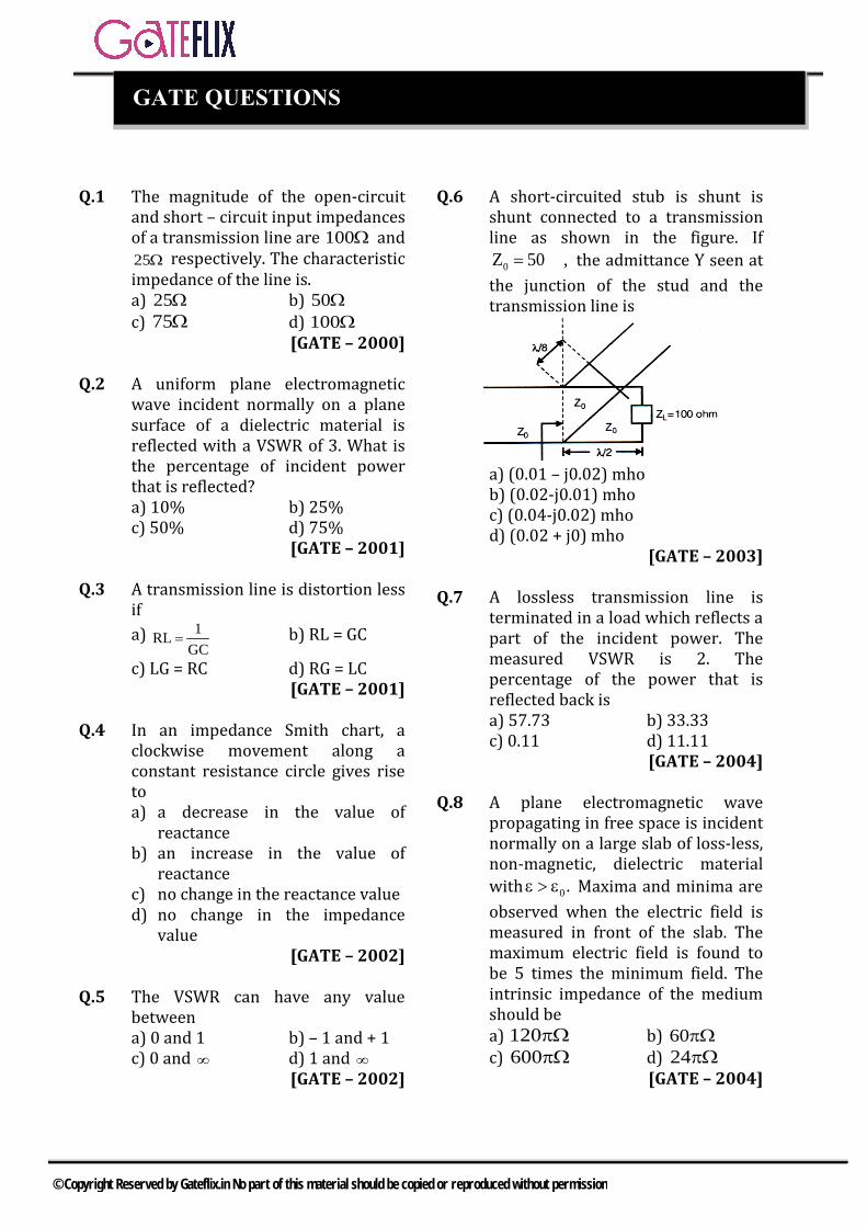
Q.1 The magnitude of the open-circuit and short – circuit input impedances of a transmission line are 100Ω and 25Ω respectively. The characteristic impedance of the line is. a) 25Ω b) 50Ωc) 75Ω d) 100Ω
[GATE – 2000]
Q.2 A uniform plane electromagnetic wave incident normally on a plane surface of a dielectric material is reflected with a VSWR of 3. What is the percentage of incident power that is reflected? a) 10% b) 25%c) 50% d) 75%
[GATE – 2001]
Q.3 A transmission line is distortion less if a) 1RL
GC= b) RL = GC
c) LG = RC d) RG = LC [GATE – 2001]
Q.4 In an impedance Smith chart, a clockwise movement along a constant resistance circle gives rise to a) a decrease in the value of
reactanceb) an increase in the value of
reactancec) no change in the reactance valued) no change in the impedance
value [GATE – 2002]
Q.5 The VSWR can have any value between a) 0 and 1 b) – 1 and + 1 c) 0 and ∞ d) 1 and ∞
[GATE – 2002]
Q.6 A short-circuited stub is shunt is shunt connected to a transmission line as shown in the figure. If
0Z 50 ,= Ω the admittance Y seen at the junction of the stud and the transmission line is
a) (0.01 – j0.02) mhob) (0.02-j0.01) mhoc) (0.04-j0.02) mhod) (0.02 + j0) mho
[GATE – 2003]
Q.7 A lossless transmission line is terminated in a load which reflects a part of the incident power. The measured VSWR is 2. The percentage of the power that is reflected back is a) 57.73 b) 33.33c) 0.11 d) 11.11
[GATE – 2004]
Q.8 A plane electromagnetic wave propagating in free space is incident normally on a large slab of loss-less, non-magnetic, dielectric material with 0.ε > ε Maxima and minima are observed when the electric field is measured in front of the slab. The maximum electric field is found to be 5 times the minimum field. The intrinsic impedance of the medium should be a) 120πΩ b) 60πΩc) 600πΩ d) 24πΩ
[GATE – 2004]
GATE QUESTIONS
© Copyright Reserved by Gateflix.in No part of this material should be copied or reproduced without permission

Q.9 Consider an impedance Z=R+jX marked with port P in an impedance Smith chart as shown in the figure. The movement from point P along a constant resistance circle in the clockwise direction by an angle 450 is equivalent to
a) Adding an inductance in serieswith Z
b) Adding a capacitance in serieswith Z
c) Adding an inductance in shuntacross Z
d) Adding a capacitance in shuntacross Z
[GATE – 2004]
Q.10 Consider a 300Ω , quarter-wave long (at 1 GHz) transmission line as show in the figure. It is connected to a 10V. 50Ω source at one end and is left open circuited at the other end. The magnitude of the voltage at the open circuit end of the line is
a) 10 V b) 5 Vc) 60 V d) 60/7 V
[GATE – 2004]
Q.11 Many circles are drawn in a smith chart used for transmission line calculation. The circles shown in the figure represent
a) Unit circlesb) Constant resistance circlesc) constant reactance circlesd) constant reflection coefficient
circles [GATE – 2005]
Common data for questions 12 and 13 Voltage standing wave pattern in a lossless transmission line with characteristic impedance 50Ω and a resistive load is shown in the figure.
Q.12 The value of the load resistance is a) 50Ω b) 200Ωc) 12.5Ω d) 0Ω
[GATE – 2005]
Q.13 The reflection coefficient is given by a) -0.6 b) -1c) 0.6 d) 0
[GATE – 2005]
Q.14 Characteristic impedance of transmission line is 50Ω . Input impedance of the open circuited line is OCZ 100 j150 .= + Ω When the transmission line is short-circuited, then value of the input impedance will be a) 50Ω b) 100 j150+ Ωc) 7.69 j11.54+ Ω d) 7.69 j11.54− Ω
[GATE – 2005]
Common data for questions 15 & 16: A 30-volts battery with zero source resistance is connected to a coaxial line of characteristic impedance of 50 ohms at t=0 second and terminated in an unknown resistive load, the line length is such that it takes 400 sµ for an electromagnetic wave
© Copyright Reserved by Gateflix.in No part of this material should be copied or reproduced without permission

to travel from source end to load end and vice – versa. At t = 400 sµ , the voltage at the load end is found to be 40 volts. Q.15 The load resistance is a) 25 ohms b) 50 ohms c) 75 ohms d) 100 Ohms
[GATE – 2006] Q.16 The steady – state current through
the load resistance is a) 25 Amps b) 0.3 Amps
c) 0.6 Amps d) 0.4 Amps [GATE – 2006]
Q.17 The parallel branches of a 2-wire
transmission line are terminated in 100Ω and 200Ω resistors as shown in the figure. The characteristic impedance of the line is 0Z 50= Ω and each section has length of / 4λ . The voltage reflection coefficient Γ at the input is
a) 7j5
− b) 57−
c) 5j7
d) 57
[GATE – 2007]
Q.18 A load of 50Ω is connected in shunt
in a 2-wire transmission line of 0Z 50= Ω as shown in the figure. The
2-port scattering parameter matrix (S-Matrix) of the shunt element is
a)1 12 2
1 12 2
− −
b) 0 11 0
c) 1 23 3
2 13 3
− −
d) 1 34 43 14 4
− −
[GATE – 2007 ] Q.19 In the design of a single mode step
index optical fiber closer upper cut – off, the single – mode operation is not preserved if a) radius as well as operating
wavelength are halved b) radius as well as operating
wavelength are doubled c) radius is halved and operating
wavelength is doubled d) radius is doubled and operating
wavelength is halved [GATE –2008]
Q.20 One end of a loss-less transmission
line having the characteristic impedance of 75Ω and length of 1 cm is short-circuited. At 3 GHz, the input impedance at the other end of the transmission line is
a) 0 b) Resistive c) Capacitive d) Inductive
[GATE –2008]
Q.21 A transmission line terminates in two branches, each of length / 4,λas shown. The branches are terminated by 50Ω loads. The lines are lossless and have the characteristic impedance shown. Determine the impedance Zi as seen by the source.
© Copyright Reserved by Gateflix.in No part of this material should be copied or reproduced without permission

a) 200Ω b) 100Ωc) 50Ω d) 25Ω
[GATE – 2009]
Q.22 In the circuit shown, all the transmission line sections are lossless. The voltage standing wave ratio (VSWR) on the 60Ω line is
a) 1.00 b) 1.64c) 2.50 d) 3.00
[GATE–2010]
Q.23 A transmission line has a characteristic impedance of 50Ω and a resistance of 0.1 / m.Ω If the line is distortion less, the attenuation constant (in Np/m) is a) 500 b) 5c) 0.014 d) 0.002
[GATE – 2010]
Q.24 A transmission line of characteristic impedance 50Ω is terminated in a load impedance as LZ . The VSWR of the line is measured as 5 and the first of the voltage maxima in the line is observed at a distance of
/ 4λ from the load. The value of LZis a) 10Ωb) 250Ωc) (19.23 j46.15)+ Ωd) (19.23 j46.15)− Ω
[GATE – 2011]
Q.25 A transmission line of characteristic impendence 50Ω is terminated by a 50Ω load. When excited by a sinusoidal voltage source at 10GHz, the phase difference between two points spaced 2mm apart on the line
is found to be / 4π radians. The phase velocity of the wave along the line is a) 80.8 10 m / s× b) 81.2 10 m / s×c) 81.6 10 m / s× d) 83 10 m / s×
[GATE – 2011]
Q.26 A transmission line with a characteristic impedance of 100Ω is used to match a 50Ω section to a 200Ω section. If the matching is to be done both at 429 MHz and 1GHz, the length of the transmission line can be approximately a) 82.5 cm b) 1.05 mc) 1.58 m d) 1.75 m
[GATE – 2012]
Q.27 The return loss of a device is found to be 20dB. The voltage standing wave ratio (VSWR) and magnitude of reflection coefficient are respectively a) 1.22 and 0.1 b) 0.81 and 0.1c) -1.22 and 0.1 d) 2.44 and 0.2
[GATE – 2013]
Q,28 For a parallel plate transmission line, let v be the speed of propagation and Z be the
characteristic impedance. Neglecting fringe effects, a reduction of the spacing between the plates by a factor of two results in
(A) halving of v and no change in Z (B) no change in v and halving of Z
(C) no change in both v and Z D) halving of both v and Z
[GATE – 2014-1]
Q.29 The input impedance of a λ8
section
of a lossless transmission line of characteristic impedance 50 Ω is
© Copyright Reserved by Gateflix.in No part of this material should be copied or reproduced without permission
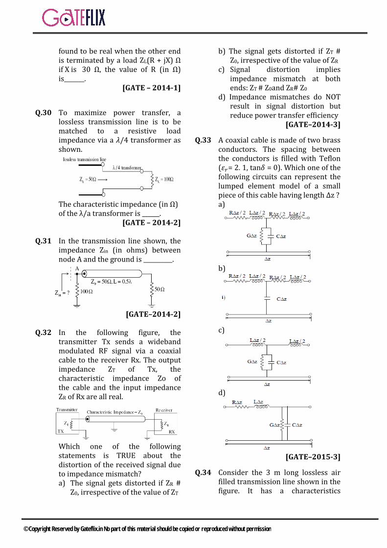
found to be real when the other end is terminated by a load ZL(R + jX) Ω if X is 30 Ω, the value of R (in Ω) is_______.
[GATE – 2014-1]
Q.30 To maximize power transfer, a lossless transmission line is to be matched to a resistive load impedance via a 𝜆𝜆/4 transformer as shown.
The characteristic impedance (in Ω) of the λ/a transformer is ______.
[GATE – 2014-2]
Q.31 In the transmission line shown, the impedance Zin (in ohms) between node A and the ground is __________.
[GATE–2014-2]
Q.32 In the following figure, the transmitter Tx sends a wideband modulated RF signal via a coaxial cable to the receiver Rx. The output impedance ZT of Tx, the characteristic impedance Zo of the cable and the input impedance ZR of Rx are all real.
Which one of the following statements is TRUE about the distortion of the received signal due to impedance mismatch?
a) The signal gets distorted if ZR # Z0, irrespective of the value of ZT
b) The signal gets distorted if ZT # Z0, irrespective of the value of ZR
c) Signal distortion implies impedance mismatch at both ends: ZT # Z0and ZR# Z0
d) Impedance mismatches do NOT result in signal distortion but reduce power transfer efficiency
[GATE–2014-3]
Q.33 A coaxial cable is made of two brass conductors. The spacing between the conductors is filled with Teflon (𝜀𝜀𝑟𝑟= 2. 1, tan𝛿𝛿 = 0). Which one of the following circuits can represent the lumped element model of a small piece of this cable having length ∆z ? a)
b)
c)
d)
[GATE–2015-3]
Q.34 Consider the 3 m long lossless air filled transmission line shown in the figure. It has a characteristics
© Copyright Reserved by Gateflix.in No part of this material should be copied or reproduced without permission
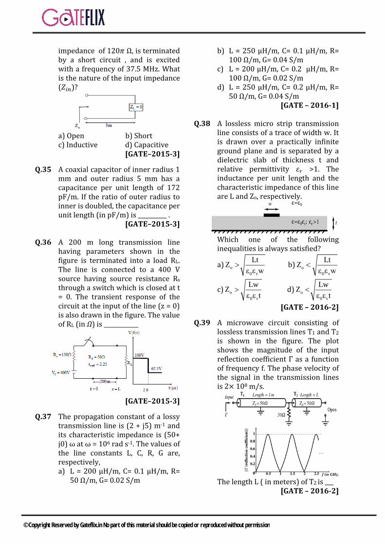
impedance of 120𝜋𝜋 Ω, is terminated by a short circuit , and is excited with a frequency of 37.5 MHz. What is the nature of the input impedance (𝑍𝑍𝑖𝑖𝑖𝑖)?
a) Open b) Shortc) Inductive d) Capacitive
[GATE–2015-3]
Q.35 A coaxial capacitor of inner radius 1 mm and outer radius 5 mm has a capacitance per unit length of 172 pF/m. If the ratio of outer radius to inner is doubled, the capacitance per unit length (in pF/m) is __________ .
[GATE–2015-3]
Q.36 A 200 m long transmission line having parameters shown in the figure is terminated into a load RL. The line is connected to a 400 V source having source resistance Rs through a switch which is closed at t = 0. The transient response of the circuit at the input of the line (z = 0) is also drawn in the figure. The value of RL (in Ω) is ____________
[GATE–2015-3]
Q.37 The propagation constant of a lossy transmission line is (2 + j5) m-1 and its characteristic impedance is (50+ j0) ω at ω = 106 rad s-1. The values of the line constants L, C, R, G are, respectively, a) L = 200 μH/m, C= 0.1 μH/m, R=
50 Ω/m, G= 0.02 S/m
b) L = 250 μH/m, C= 0.1 μH/m, R=100 Ω/m, G= 0.04 S/m
c) L = 200 μH/m, C= 0.2 μH/m, R=100 Ω/m, G= 0.02 S/m
d) L = 250 μH/m, C= 0.2 μH/m, R=50 Ω/m, G= 0.04 S/m
[GATE – 2016-1]
Q.38 A lossless micro strip transmission line consists of a trace of width w. It is drawn over a practically infinite ground plane and is separated by a dielectric slab of thickness t and relative permittivity 𝜀𝜀𝑟𝑟 >1. The inductance per unit length and the characteristic impedance of this line are L and Zo, respectively.
Which one of the following inequalities is always satisfied?
a)0
oτ
LtZε
ε w
> b)0
oτ
Ltε
Zε w
<
c)0
oτ
Lwε
Zε t
> d)0
oτ
LwZε
ε t
<
[GATE – 2016-2]
Q.39 A microwave circuit consisting of lossless transmission lines T1 and T2 is shown in the figure. The plot shows the magnitude of the input reflection coefficient Γ as a function of frequency f. The phase velocity of the signal in the transmission lines is 2× 10⁸ m/s.
The length L ( in meters) of T2 is ___ [GATE – 2016-2]
© Copyright Reserved by Gateflix.in No part of this material should be copied or reproduced without permission
Q.40 The voltage of an electromagnetic wave propagating in a coaxial cable with uniform characteristic impedance ( ) l j tV l e−γ + ω= volts,
Where l is the distance along the length of the cable in meters. ( ) 10.1 j40 m−γ = + is the complex
propagation constant, and 92 x10 rad / sω = π is the angular frequency. The absolute value of the attenuation in the cable in dB/meter is __________.
[GATE – 2017-1]
Q.41 A two – wire transmission line terminates in a television set. The VSWR measured on the line is 5.8. The percentage of power that is reflected from the television set is ______________
[GATE – 2017-1]
Q.42 A lossy transmission line has resistance per unit length R = 0.05Ω/m The line is distortionless and characteristic impedance of 50Ω The attenuation constant (in Np/m, correct to three decimal places) of the line is_____. / m.
[GATE – 2017-1]
© Copyright Reserved by Gateflix.in No part of this material should be copied or reproduced without permission
Q.1 (b) 0 .
100 25
=
= ×
OC SCZ Z Z
0 10 5 50Z = × = Ω
Q.2 (b) 11
S +Γ=
−Γ131+Γ
⇒ =−Γ
0.5Γ =2rP 0.25
iP= Γ =
25%∴ of incident power is reflected
Q.3 (c)
Q.4 (b)
Q.5 (d)
Q.6 (a)
2πβλ
=
For 2.
2dY d π λβ πλ
= × =
[ tan ]tan
o L od
o L
Z Z jZ dZZ jZ d
ββ
+=
+
d50[100 j50 tan ]Z(50 j100 tan )
100
+ π=
+ π=
1 1 0.01100d
d
YZ
= = =
For Ys’ 2 , 08 4 Ld Zπ λ πβ
λ= × = →
0
0
0
tan4
tan4
o L
S
L
Z Z jZZ jZ
Z jZ
π
π
+ = = +
0
1 1 0.02ss
Y jZ jZ
= = = −
d sY Y Y∴ = += 0.01 – 0.02j
Q.7 (d) 11
ρ +Γ=
−Γ121+Γ
⇒ =−Γ
13
⇒ Γ =
r 2P 13
ef
incP∴ = Γ =
1 2 3 4 5 6 7 8 9 10 11 12 13 14 (b) (b) (c) (b) (d) (a) (d) (d) (a) (c) (b) (c) (a) (d) 15 16 17 18 19 20 21 22 23 24 25 26 27 28 (d) (b) (d) (b) (d) (d) (d) (b) (d) (a) (c) (b) (a) (b) 29 30 31 32 33 34 35 36 37 38 39 40 41 42 40 70.7 33.3 (c) (b) (d) 120.2 30 (b) (b) 0.1 0.868 49.82 0.001
ANSWER KEY:
EXPLANATIONS
© Copyright Reserved by Gateflix.in No part of this material should be copied or reproduced without permission

⇒ 11.11% of Pi is reflected Q.8 (d)
max
min
ESWRE
=
min
min
5 5ESE
⇒ = =
1 2 251 3 3− Γ
= Γ = ∴ Γ = −− Γ
As 2 1η η<
2η 120π23 η 120π
−⇒ − =
+
2 24η π⇒ = Q.9 (a)
Movement on const. r-circle by an 045∠ in C.W. direction. R is same
and reactance increases i.e. addition of induction in series with Z.
Q.10 (c)
oL
in in
ZVV Z
=
10 300 6050LV V×
⇒ = =
Q.11 (b) Q.12 (c)
max
min
VSV
=
4 41
= =
1 ΓS1 Γ+
=−
max 0Z Z .S= min 0Z Z / S= As minima is at load,
L min50Z Z 12.5Ω4
∴ = = =
Q.13 (a)
L 0
L 0
Z Z 12.5 50GZ Z 12.5 50
− −= =
+ +
Γ 0.6= − Q.14 (d) 2
0 OC SCZ Z .Z=
SC50 50Z
100 j150×
=+
502 3j
=+
50(2 3j)13−
=
SCZ 7.69 11.54j= − Q.15 (d)
r
i
V 10 1ΓV 30 3
= = =
L 0
L 0
Z ZΓZ Z
−=
+
L
L
Z 5013 Z 50
−⇒ =
+
LZ 100Ω⇒ = Q.16 (b)
L30I 0.3A
100= =
Q.17 (d)
20
inL
Z λZ ;iflZ 4
= =
1R due to 250100Ω 25
100= =
2R due to 250 25200Ω
200 2= =
© Copyright Reserved by Gateflix.in No part of this material should be copied or reproduced without permission

1 225 25R R 252 3
⇒ = =
( )2
S
50Z 300Ω
25 / 3= =
S 0
S 0
Z ZΓZ Z
−⇒ =
+300 50 5300 50 7
−= =
+
Q.18 (b) The line is terminated with 50Ω at the center and so matched on both the sides.
Q.19 (d)
Q.20 (d) f 3GHz=
C 2πλ ,βf λ
= =
2πflβlc
=
9
8
2π 3 10 0.013 10× ×
= ××
π 36°5
= =
Input impedance
L 0in 0
0 L
Z jZ tanβlZ ZZ jZ tanβl
+= +
Given that L 0Z 0, Z 75Ω= =
0 0in
0
Z .jZ tanβlZZ
=
0jZ tanβl= j 75 tan 36°= × × j54.49Ω=
Hence , input impedance is inductive.
Q.21 (d) ( )
1
220
1L
100ZZ 200ΩZ 50
= = =
( )220
22
100ZZ 200ΩZ 50
= = =
L 1 2Z Z || Z 100Ω= =
( )220
iL
50ZZ 25ΩZ 100
= = =
a) x, y, z componentsb) x, y componentsc) y, z componentsd) x, z components
Q.22 (b)
L 0in 0
0 L
Z jZ tanβlZ ZZ jZ tanβl
+= +
Input impedance
1
2π λ0 j30 tanλ 8Z 30
30 0
+ =+
1Z j30⇒ =
2
2π λ30 j30 2 tanλ 8Z 30 2
2π λ30 2 j30 tanλ 8
+ = +
30 j30 2tan π / 230 2
30 2 j30tan π / 2
+
= +
60Ω=
Or , ( )2
2
30 2Z 60Ω
30= =
Load impedance, L 1 2Z Z Z j30 60= + = +
Magnitude of reflection coefficient,
© Copyright Reserved by Gateflix.in No part of this material should be copied or reproduced without permission
L 0
L 0
Z Z 60 j30 60ρZ Z 60 j30 60
− + −= =
+ + +
j30 j1120 j30 4 j
= =+ +
1 116 1 17
= =+
VSWR on 60Ω line, 111 ρ 17VSWR 1.611 ρ 117
++== = =
− −
Q.23 (d)
For distortion less transmission line,
L RLG RCC G
= ⇒ =
Characteristic impedance,
0L RZC G
= =
Attenuation constant,
0
Rα RG R.Z
= =
0
R 0.1Z 50
==
0.002Np / m= Q.24 (a)
1 | Γ |VSWR 51 | Γ |+
= =−
2 2Γ Γ3 3
∴ = ⇒ = ±
If maximum is at 𝜆𝜆/4 from load then minimum will be at load itself
Reflection coefficient Γ Γ= jθe
Where , vmx 1θ 720°λ 4
= −
vmx =distance of minima from load Here vmx 0= So, θ 180°= − Therefore , 180Γ Γ −= j °e
2Γ3
⇒ = −
Now L 0 L
L 0 0
Z Z Z 5023 Z Z Z 50
− −− = =
+ +
LZ 10Ω⇒ = Q.25 (c)
Phase difference 2=
πλ
(path
difference)
3π 2π (2 10 )4 λ
−⇒ = ×
3λ 8 2 10−∴ = × × 316 10 m−= × 9f 10GHz 10 10 Hz= = ×
Hence the phase velocity of wave along the line is
9 3v fλ 10 10 16 10−= = × × × 8v 1.6 10 m / s∴ = × Q.26 (b) Q.27 (a)
1 | Γ |VSWR1 | Γ |+
=−
Only options (a) satisfy this 1 01 1.1 1.221 0.1 0.9+
= =−
.
Q.28 (b)
or
lo276 dZr
g =
d → distance between the two plates so, 𝑍𝑍𝑜𝑜 — changes, if the spacing between the plates changes.
V= 1LC
→ independent of spacing
between the plates Q.29 (40) Given, ℓ = λ s
Zo =50 Ω
( ) L oin
oo
L
Z JZλZ 8 Z KZ
Z +
= = + l
© Copyright Reserved by Gateflix.in No part of this material should be copied or reproduced without permission

Lin
L
Z J50Z 5050 JZ +
= +
L L
L L
Z J50 50 JZ5050 JZ 50 JZ + −
= × + − 2 2
L L Lin 2 2
L
50Z 50Z j(50 Z )Z 5050 Z
+ + −= +
Given, 𝑍𝑍𝑖𝑖𝑖𝑖 → Real So, Img (Zin) = 0 502— 𝑍𝑍𝐿𝐿2 =0 ZL2 = 502 R2 = 502 − X2 = 502 − 302 R=40Ω
Q.30 (70.7) Here impedance is matched by using QWT ( )4
λ
∴ Z0′ = ZLZin = √100 × 50 =50√2 =𝑍𝑍0
′ =70.7Ω
Q.31 (33.33)
Here λ2
=l
( )in LλZ Z 502= = =l Ω
( )inZ 100 || 50∴ =
100 33.333
= = Ω
Q.32 (c) Signal distortion implies impedance mismatch at both ends. i.e., ZT # Z0 ZR # Z0
Q.33 (b)
Loss tangent tan𝛿𝛿 = 0 = σω
𝜎𝜎 = 0 G → Conductivity of the dielectric material So, 𝜎𝜎 = 0 = G
Q.34 (d)
in 0z JZ tanβl= 2π 2π 3πβl .l (3)λ 8 4
= = =
8
6
3 10λ 837.5 10
×= =
×Short circuited line
π0 βl inductor2
< →
π βl π Capacitor2< < →
Q.35 (120.22) 2π lC
bIna
=
1C 2π C
bl Ina
= =
2
1 2
121
bIn(C a )bC In( a )
=
2
10In(172pF 1)C In(5)
=
2In(5)C 172pFIn(10)
=
2C 120.22pF=
Q.36 (30)
Given V(t 2 s,Z=0)=62.5= µ ( ) ( ) ( )62.5 V t 0, z 0 V t 1, z 0 V t 2, z 0= = = + = = + = =
62.5 100= +
Q.37 (b) We know
© Copyright Reserved by Gateflix.in No part of this material should be copied or reproduced without permission

( )( ) ( )δ R jωL G jωL .. 1= + + …
0R jωLz .(2)G jωL+
= …………+
From (1) and (2) 0R jωL z δ 50 (2 j5)+ = × = × + ⟹R =100Ω/m & L = 250μH/m From (1) and (2)
0
G δ 2 j5z 5
j c0+
=+ ω =
0.04sG & c 0.1μF / mm
⇒ = =
Q.38 (b) Q.39 (0.1) Q.40 0.8686 (0.85-0.88) Given ( ) 10.1 j40 m−γ = +
Here p0.1 / mα = ω
We know that p1 / m 8.686dB / mω =
p0.1 / m 0.8686dB / mω =
Q.41 49.82 %(48.0-51.0)
Percentage of power reflected is 2 x100Γ
VSWR 1VSWR 1
5.8 1 4.8 0.70585.8 1 6.8
−Γ =
+−
= = =+
% Power reflected 2 x100 49.82%Γ =
Q.42 0.001
Given R = 0.05Ω/m
Condition for distortion less transmission line
0
2
RC LGR LG CR 50x50 R GG
L z 50C
L 50C
=
=
= ⇒ =
= =
⇒ =
Alternation constant= RG
0.05x0.05 0.05 0.00150x50 50
= = =
© Copyright Reserved by Gateflix.in No part of this material should be copied or reproduced without permission

EM waves cannot travel like a single ray or a uniform beam as discussed in the previous sections. EM wave tends to open out by forming spherical wavefronts and hence reducing the power density of the wave as its travel forward.
A waveguide can be used to confine the wave within the stipulated limits and can therefore give directionality for a wave. This helps the EM wave to have same power density without having to get weakened.
The most popular waveguides are:
Parallel Plane waveguides – for 1-dimensional restriction of the wave.
Rectangular waveguides – for 2-dimensional restriction of the wave.
7.1 PARALLEL PLANE WAVEGUIDES:
Consider a wave having E(x, z, t)/H(x, z, t) between two infinite conducting sheets at x = 0 and x = a
The wave is assumed to expand in x-direction only and not in y-direction and wave is expected to propagate in the z-direction. The boundary conditions for ‘a’, the conductor can be defined as Etan = 0, i.e. no E-field can exist parallel to the conductor of surface.
7.2 WAVE BEHAVIOUR BETWEEN GUIDES:
When 2
20 0
maπ γ = −ω µ ε
There are only two possibilities for γ
i.e. γ = real when 2
20 0
maπ > ω µ ε
j0= α +
= only attenuation of E field but no wave or phase changes exist.
γ = imaginary when 2
20 0
maπ ω µ ε >
0 j= + β
= An un-attenuated wave exists.
7 WAVEGUIDES
© Copyright Reserved by Gateflix.in No part of this material should be copied or reproduced without permission

7.3 CUT-OFF FREQUENCY
For wave propagation to exist between the guides, the frequency ' 'ω should be sufficiently large enough, else there cannot be wave propagation possible. Every guide has a cut-off frequency below which waves cannot propagate in the guide.
22
0 0maπ ω µ ε >
0 0
ma
πω >
µ ε
c cut off frequencyω = −
cm c
aπ
ω =
cmcf2a
=
0 0
1c freespace velocity= =µ ε
c2am
λ = m = integer 0, 1, 2, 3
…
7.4 PHASE VELOCITY & GUIDE WAVELENGTH:
The velocity of the wave when represented as phase velocity
pV ω=β
22
0 0maπ β = ω µ ε −
P 22
0 0
Vma
ω=
π ω µ ε −
2
0 0
1
ma
=π µ ε − ω
The PV expression can be rewritten as,
g 2c
cff1f
λλ =
−
The wavelength of the wave in the guide is therefore larger than that in free-space due to the increased phase change, such that exactly at the guide walls E field has zero value.
P 2
0 0
cVm1
a
= π
− ω µ ε
P 2c
cV
1
=ω − ω
2c
c
f1f
= −
© Copyright Reserved by Gateflix.in No part of this material should be copied or reproduced without permission

As seen in the above equation, p cV V> implies that the phase changes of the wave are faster than in free space. The wave has a dynamic change in rate of phase change with distance ( )β that is essential tosatisfy the boundary conditions at the conducting walls.
7.4.1 GROUP VELOCITY
The velocity of a wave can be expressed as
pV ω=β
When the phase changes with time and space are linear to each other i.e. β∝ ω . Otherwise, in all other circumstances term group velocity is used to represent the propagation rate.
gdVdω
=β
In guided waves as gλ is increased due to changes in phase with space being changed, vg represents the energy propagation rate such that
2p gV V c=
Hence
gV ccos= θ
Hence, no propagation exists exactly at cut-off frequencies.
7.5 WAVE ANGLE
Every wave above cf travels along the guide axis in a pre-determined angle that depends on how larger is f over cf . At exact
cf there is no propagation along the axis but oscillates.
When
cmcf2a
= cf ''' f '' f ' f> > >
The angle made with the guide walls is called as wave angle, such that
cfsinf
θ =
pcV
cos⇒ =
θ
g cosλ
λ =θ
Note that cf f= , 90θ = and as the frequency increase angle made with the walls decreases.
7.6 MODES OF OPERATION
cmcf2a
= when m = 1
ccf
2a=
is the least cut-off frequency of the guide and all the frequencies above cf and below
© Copyright Reserved by Gateflix.in No part of this material should be copied or reproduced without permission

c2f propagate in the guide as shown below.
Similarly all frequencies from c2f to c3f propagation as shown. They have their own wave angles depending on their frequency.
7.7 RECTANGULAR WAVEGUIDES
A parallel plane waveguide confines waves in one dimension only. A more practical waveguide needs to confine the wave in both the dimensions and allow propagation in one dimensions.
A rectangular waveguide has two sets of finite conducting sheets as shown below.
Both x and y dimensions are restricted by
the sheets and hence xmaπ
γ = and ynbπ
γ =
Propagation constant
2 22
0 0m na bπ π γ = + −ω µ ε
Cut-off frequency of the guide is
2 2
cm n ca b
π π ω = +
2 2
c
m n ca b
f2
π π + =
π
Phase velocity of the guide is
p 2c
cVf1f
= −
Wave angle
cfsinf
θ =
TE/ TM/ TEM waves in guided conditions
( ) ( ) ( )x y zE x, y, z , E x, y, z , E x, y, z
( ) ( ) ( )x y zH x, y, z ,H x, y, z ,H x, y, z
© Copyright Reserved by Gateflix.in No part of this material should be copied or reproduced without permission

7.8 TE WAVES IN RECTANGULAR WAVEGUIDES
zx x0
n m nE E cos x sin y eb a b
−γπ π π =
zy y0
m m nE E sin x cos y ea a b
−γπ π π =
zx x0
m m nH H sin x cos y ea a b
−γπ π π =
zy y0
n m nH H cos x sin y eb a b
−γπ π π =
zz z0
m nH H cos x cos y ea b
−γπ π =
7.9 DOMINATE MODE OF TE WAVES
When m = 0 and n = 1
zx x0
n nE E sin y eb b
−γπ π =
zy y0
n nH H sin y eb b
−γπ π =
zz z0
nH H cos y eb
−γπ =
When n = 0 and m = 1
zx x0
m mH H sin x ea a
−γπ π =
zy y0
m mE E sin x ea a
−γπ π =
zz z0
mH H cos x ea
−γπ =
The dominant mode is TE10 or TE01
The existing modes are TEmo or TEon and TEmn
7.10 TM WAVES IN RECTANGULAR WAVEGUIDE
zx x0
m m nE E cos x sin y ea a b
−γπ π π =
zy y0
n m nE E sin x cos y eb a b
−γπ π π =
zz z0
m nE E sin x sin y ea b
−γπ π =
zx x0
n m nH H sin x cos y eb a b
−γπ π π =
zy y0
m m nH H cos x sin y ea a b
−γπ π π =
7.11 DOMINATE MODE IN TM WAVES
When m = 0 or n = 0, all components of E and H vanish. Dominant mode is TM11. The existing modes are TMmn only.
7.12 NUMERICAL APERTURE
The most important parameter of an optical fiber is its numerical aperture (NA). The value of NA is decided by the refracted indices of the core and the cladding.
By definition, the refractive index n of a medium is defined as
speed of light in vaccumnspeed of light in medium
=
0 0
m
m m
1c
1µ ε
= =µ
µ ε
(1)
Since m 0µ = µ in most practical cases,
© Copyright Reserved by Gateflix.in No part of this material should be copied or reproduced without permission

mr
0
n ε= = ε
ε (2)
indicating that the refractive index is essentially the square-root of the dielectric constant.
Keep in mind that rε can be complex. For common materials, n = 1 for air, n = 1.33 for water, and n = 1.5 for glass.
As a light ray propagates from medium 1 to medium 2, Snell’s law must be satisfied.
1 1 2 2n sin n sinθ = θ (3)
Where 1θ is the incident angle in medium 1 and 2θ is the transmission angle in medium 2.
The total reflection occurs when 2 90θ = , resulting in
1 21 c
1
nsinn
−θ = θ = (4)
Another way of looking at the light-guiding capability of fiber is to measure the acceptance angle aθ , which is the maximum angle over which light rays entering the fiber will be trapped in its core. We know that the maximum angle occurs when cθ is the critical angle, there by satisfying the condition for total internal reflection. Thus, for a step-index fiber.
2 2a 1 c 1 2NA sin n sin n n= θ = θ = − (5)
Where 1n is the refractive index of the core and 2n is the refractive index of the cladding as shown in figure.
Since most fiber cores are made of silica 1n 1.48= . Typical values of NA range
between 0.19 and 0.25. The larger the value of NA, the more optical power the fiber can capture from a source. Because such optical fibers may support the numerous modes, they are called multi-mode step-index fibers. The mode volume V is given by
2 21 2
dv n nπ= −λ
(6)
Where d is the fiber core diameter and λ is the wavelength of the optical source. From equation (6), the number N of modes propagating in a step-index fiber can be estimated as
2vN2
= (7)
7.13 ATTENUATION
Attenuation is the reduction in the power of the optical signal. Power attenuation (or fiber loss) in an optical fiber is governed by
dp pdz
= −α (8)
Where α the attenuation and p is the optical power. In equation (8), it is assumed that a wave propagates along z. By solving equation (8), the power p (0) at the input of the fiber and the power p (l) of the light after l are related as
© Copyright Reserved by Gateflix.in No part of this material should be copied or reproduced without permission

( ) ( ) zp l p 0 e−α= (9)
It is customary to express attenuation α in decibels per kilometer and length l of the fiber in kilometers. In this case equation (9) becomes
( )( )l 10
p 010log
p 1α =
Thus, the power of the light reduces by α decibels per kilometer as it propagates, through the fiber. Equation (10) may be written as
( ) ( ) l/10p p p 0 10−α= =
For l 100km=
( )( )
100
2
10 For coaxialcablep 0p l 10 For Fiber
−
−
Deciding that much more power is lost in the coaxial cable than in fiber.
7.14 DISPERSION
The spreading of pulses of light as they propagate down a fiber is called dispersion. As the pulses representing 0s spread, they overlap epochs that represent 1s. Dispersion is beyond a certain limit. It may confuse the receiver. The dispersive effects in single mode fibers are much smaller than in multimode fibers.
© Copyright Reserved by Gateflix.in No part of this material should be copied or reproduced without permission

Q.1 A rectangular waveguide has dimensions 1cm 0.5cm,× Its cut-off frequency is a) 5 GHz b) 10 GHzc) 15 GHz d) 12 GHz
[GATE – 2000]
Q.2 A TEM wave is incident normally upon a perfect conductor. The E and H fields at the boundary will be. Respectively, a) minimum and minimumb) maximum and maximumc) minimum and maximumd) maximum and minimum
[GATE – 2000]
Q.3 The dominant mode in a rectangular waveguide is 10TE because this mode has a) no attenuationb) no cut-offc) no magnetic field componentd) the highest cut-off wavelength
[GATE – 2001]
Q.4 The phase velocity of waves propagating in a hollow metal waveguide is a) greater than the velocity of light
in free spaceb) less than the velocity of light in
free spacec) equal to the velocity of light in
free spaced) equal to the group velocity
[GATE – 2001]
Q.5 The phase velocity for the 10TEmode in an air-filled rectangular waveguide is a) Less than c b) equal to cc) Greater to c d) none of the above
Note: (c is the velocity of plane waves in free space)
[GATE – 2002]
Q.6 A rectangular metal wave guide filled with a dielectric material of relative permittivity r 4ε = has the inside dimensions 3.0cm 1.2cm.× The cut-off frequency for the dominant mode is a) 2.5 GHz b) 5.0 GHzc) 10.0 GHz d) 12.5 GHz
[GATE – 2003]
Q.7 The phase velocity of an electromagnetic wave propagating in a hallow metallic rectangular waveguide in the 10TE mode is a) equal to its groups velocityb) less than the velocity of light in
free spacec) equal to the velocity of light in
free spaced) greater than the velocity of light
in free space[GATE – 2004]
Q.8 Which one of the following does represent the electric field lines for the 02TE mode in the cross-section of a hollow rectangular metallic waveguide?
a)
b)
GATE QUESTIONS
© Copyright Reserved by Gateflix.in No part of this material should be copied or reproduced without permission
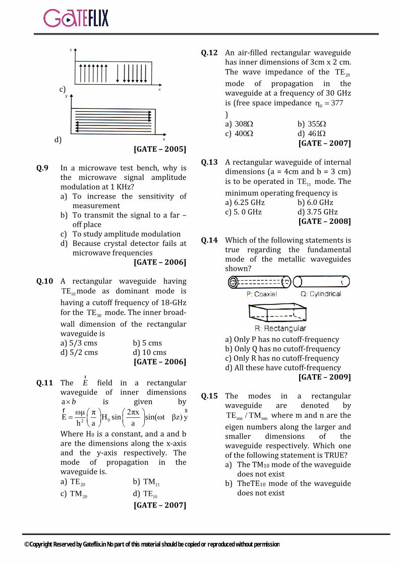
c)
d) [GATE – 2005]
Q.9 In a microwave test bench, why is the microwave signal amplitude modulation at 1 KHz? a) To increase the sensitivity of
measurementb) To transmit the signal to a far –
off placec) To study amplitude modulationd) Because crystal detector fails at
microwave frequencies [GATE – 2006]
Q.10 A rectangular waveguide having 10TE mode as dominant mode is
having a cutoff frequency of 18-GHz for the 30TE mode. The inner broad-wall dimension of the rectangular waveguide is a) 5/3 cms b) 5 cmsd) 5/2 cms d) 10 cms
[GATE – 2006]
Q.11 The rE field in a rectangular
waveguide of inner dimensions a×b is given by
02
ωμ π 2πxE H sin sin(ωt βz) yh a a
= −
$r
Where H0 is a constant, and a and b are the dimensions along the x-axis and the y-axis respectively. The mode of propagation in the waveguide is. a) 20TE b) 11TMc) 20TM d) 10TE
[GATE – 2007]
Q.12 An air-filled rectangular waveguide has inner dimensions of 3cm x 2 cm. The wave impedance of the 20TE mode of propagation in the waveguide at a frequency of 30 GHz is (free space impedance 0 377η = Ω) a) 308Ω b) 355Ωc) 400Ω d) 461Ω
[GATE – 2007]
Q.13 A rectangular waveguide of internal dimensions (a = 4cm and b = 3 cm) is to be operated in 11TE mode. The minimum operating frequency is a) 6.25 GHz b) 6.0 GHzc) 5. 0 GHz d) 3.75 GHz
[GATE – 2008]
Q.14 Which of the following statements is true regarding the fundamental mode of the metallic waveguides shown?
a) Only P has no cutoff-frequencyb) Only Q has no cutoff-frequencyc) Only R has no cutoff-frequencyd) All these have cutoff-frequency
[GATE – 2009]
Q.15 The modes in a rectangular waveguide are denoted by
mn mnTE / TM where m and n are the eigen numbers along the larger and smaller dimensions of the waveguide respectively. Which one of the following statement is TRUE? a) The TM10 mode of the waveguide
does not existb) TheTE10 mode of the waveguide
does not exist
© Copyright Reserved by Gateflix.in No part of this material should be copied or reproduced without permission
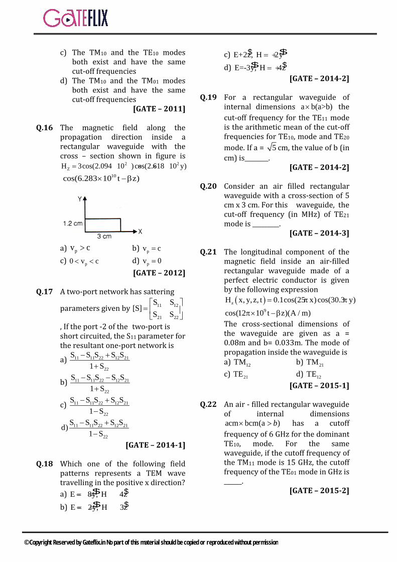
c) The TM10 and the TE10 modes both exist and have the same cut-off frequencies
d) The TM10 and the TM01 modes both exist and have the same cut-off frequencies
[GATE – 2011]
Q.16 The magnetic field along the propagation direction inside a rectangular waveguide with the cross – section shown in figure is
2 2ZH 3cos(2.094 10 )cos(2.618 10 y)= × × ×
10cos(6.283 10 t z)× −β
a) pv c> b) pv c= c) p0 v c< < d) pv 0=
[GATE – 2012] Q.17 A two-port network has sattering
parameters given by 11 12
21 22
S S[S]
S S
=
, If the port -2 of the two-port is short circuited, the S11 parameter for the resultant one-port network is
a) 11 11 22 12 21
22
S S S S S1 S
− ++
b) 11 11 22 12 21
22
S S S S S1 S
− −+
c) 11 11 22 12 21
22
S S S S S1 S
− +−
11 11 22 12 21
22
S S S S Sd)1 S
− +−
[GATE – 2014-1] Q.18 Which one of the following field
patterns represents a TEM wave travelling in the positive x direction?
a) $E 8y, H 4z= + = − $ b) $E 2y, H 3z = − = − $
c) $E+2z, H 2y = +$ d) $E=-3y, H 4z = + $
[GATE – 2014-2] Q.19 For a rectangular waveguide of
internal dimensions a b(a>b)× the cut-off frequency for the TE11 mode is the arithmetic mean of the cut-off frequencies for TE10, mode and TE20
mode. If a = 5 cm, the value of b (in cm) is________.
[GATE – 2014-2] Q.20 Consider an air filled rectangular
waveguide with a cross-section of 5 cm x 3 cm. For this waveguide, the cut-off frequency (in MHz) of TE21 mode is _________.
[GATE – 2014-3] Q.21 The longitudinal component of the
magnetic field inside an air-filled rectangular waveguide made of a perfect electric conductor is given by the following expression
( )z x, y, z, t 0.1cos(25 x)cos(30 )H .3 y= π π
9cos(12 10 t z)(A / m)π× −β The cross-sectional dimensions of the waveguide are given as a = 0.08m and b= 0.033m. The mode of propagation inside the waveguide is a) 12TM b) 21TM c) 21TE d) 12TE
[GATE – 2015-1] Q.22 An air - filled rectangular waveguide
of internal dimensions cm bcm )a (a× > b has a cutoff
frequency of 6 GHz for the dominant TE10, mode. For the same waveguide, if the cutoff frequency of the TM11 mode is 15 GHz, the cutoff frequency of the TE01 mode in GHz is ______.
[GATE – 2015-2]
© Copyright Reserved by Gateflix.in No part of this material should be copied or reproduced without permission

Q.23 Light from free space is incident at an angle iθ to the normal of the facet of a step-index large core optical fibre. The core and cladding refractive indices are 1n 1.5= and
2n 1.4= , respectively.
The maximum value of θi (in degrees) for which the incident light will be guided in the core of the fibre is ___________.
[GATE – 2016-2]
Q.24 An optical fiber is kept along the zdirection. The refractive indices for the electric fields along x and y directions in the fiber are nx = 1.5000 and ny = 1.5001 respectively ( x yn n≠ due to the imperfection in the fiber cross-section). The free space wavelength of a light wave propagating in the fiber is 1.5 µm. If the light wave is circularly polarized at the input of the fiber, the minimum propagation distance after which it becomes linearly polarized, in centimeter, is ___________.
[GATE – 2017-1]
Q.25 Standard air – filled rectangular waveguides of dimensions a = 2.29 cm and b= 1.02 cm are designed for radar applications. It is desired that these waveguides operate only in the dominant TE10 mode but not higher than 95% of the next higher cutoff frequency. The range of the allowable operating frequency f is.
a) 8.19GHz f 13.1GHz≤ ≤
b) 8.19GHz f 12.45GHz≤ ≤
c) 6.55GHz f 13.1GHz≤ ≤
d) 1.64GHz f 10.24GHz≤ ≤
[GATE – 2017-2]
Q.26 The permittivity of water at optical frequencies is 1.75 0ε It is found that an isotropic light source at a distance d under water forms an illuminated circular area of radius 5m, as shown in the figure. The critical angle is cθ
The value of d (in meter) is _____________ .
[GATE – 2017-2]
Q.27 The cutoff frequency of TE01 mode of an air filled rectangular waveguide having inner dimensions a cm × b cm (a > b) is twice that of the dominant TE10 mode. When the waveguide is operated at frequency which is 25% higher than the cutoff frequency of the dominant mode, the guide wavelength is found to be 4 cm. The value of b (in cm, correct to two decimal places) is ____.
[GATE – 2018]
© Copyright Reserved by Gateflix.in No part of this material should be copied or reproduced without permission

Q.28 The distance (in meters) a wave has to propagate in a medium having a skin depth of 0.1m so that the amplitude of the wave attenuates by 20 dB, is a) 0.12 b) 0.23 c) 0.46 d) 2.3 [GATE – 2018]
1 2 3 4 5 6 7 8 9 10 11 12 13 14 (c) (a) (d) (a) (c) (a) (d) (d) (d) (c) (a) (c) (a) (a) 15 16 17 18 19 20 21 22 23 24 25 26 27 28 (a) (a) (b) (b) 2 7810 (c) 13.7 32.5 0.375 (b) 4.33 0.75 (b)
ANSWER KEY:
© Copyright Reserved by Gateflix.in No part of this material should be copied or reproduced without permission
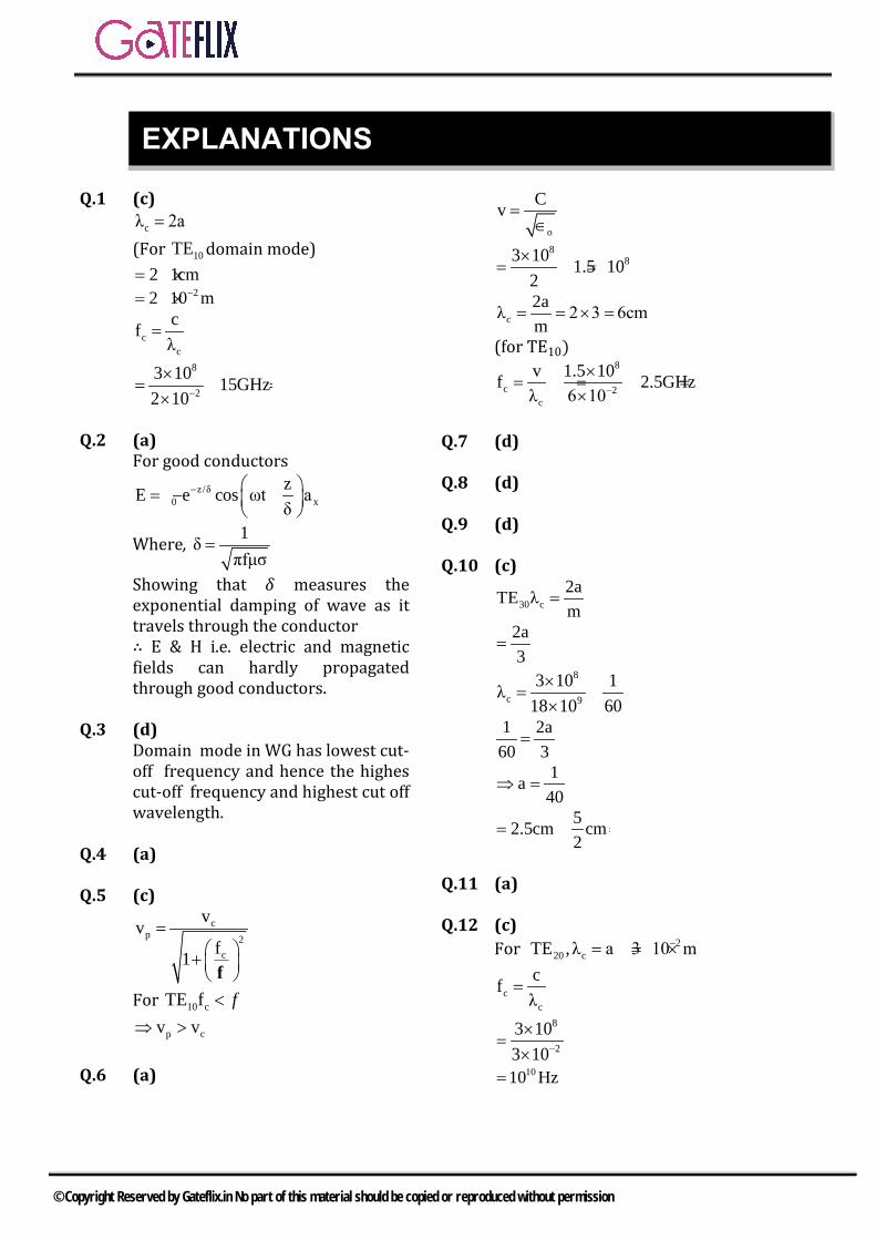
Q.1 (c) cλ 2a=
(For 10TE domain mode) 2 1cm= ×
22 10 m−= ×
cc
cfλ
=
8
2
3 10 15GHz2 10−
×= =
×
Q.2 (a) For good conductors
z/δ0 x
zE e cos ωt aδ
− =∈ −
Where, 1δπfμσ
=
Showing that 𝛿𝛿 measures the exponential damping of wave as it travels through the conductor ∴ E & H i.e. electric and magnetic fields can hardly propagated through good conductors.
Q.3 (d) Domain mode in WG has lowest cut-off frequency and hence the highes cut-off frequency and highest cut off wavelength.
Q.4 (a)
Q.5 (c) c
p 2c
vvf1
= + f
For 10 cTE f < f
p cv v⇒ >
Q.6 (a)
o
Cv =∈
883 10 1.5 10
2×
= = ×
c2aλ 2 3 6cmm
= = × =
(for TE10) 8
c 2c
v 1.5 10f 2.5GHzλ 6 10−
×= = =
×
Q.7 (d)
Q.8 (d)
Q.9 (d)
Q.10 (c)
30 c2aTE λm
=
2a3
=
8
c 9
3 10 1λ18 10 60×
= =×
1 2a60 3
=
1a40
⇒ =
52.5cm cm2
= =
Q.11 (a)
Q.12 (c) For 2
20 cTE ,λ a 3 10 m−= = ×
cc
cfλ
=
8
2
3 103 10−
×=
×1010 Hz=
EXPLANATIONS
© Copyright Reserved by Gateflix.in No part of this material should be copied or reproduced without permission

1
2c
nnf1f
= −
210
10
377
1013 10
=
− ×
1n 400Ω= Q.13 (a) Minimum operating frequency
2 2
0C m nf2 a b
= +
For 11TE mode ,
2 28
03 10 1 1f
2 0.04 0.03× = +
83 10 0.05
2 0.04 0.03×
= ××
6.25GHz= Q.14 (a)
P is coaxial line and support TEM wave ∴ P has no cut-off frequency Q and R waveguides and cut-off frequency of each depends upon their dimensions.
Q.15 (a)
In case of rectangular wave guide mnTE exist for all values of m and
except m=0 and n=0 For mnTE to exist both values of m ad n must be non zero.
Q.16 (a)
Phase velocity is always greater than C inside a waveguide while group velocity is always less than c is inside a waveguide.
Q.17 (b)
1 11 1 12 2b s a s a= + 2 21 1 22 2b s a s a= +
2
1 11 12 1 11
2 21 22 2 1 a 0
b S S a b; Sb S S a a
=
= =
By verification Answer B satisfies. Q.18 (b)
For TEM wave Electric field (E), Magnetic field (H) and Direction of propagation (P) are orthogonal to each other.
Here P = + ax By verification y, z,2α HE 3α− = −= y, z, xH α α αE× = − ×− = + P→ Q.19 (2)
2
c10C 1t2 a
=
c10 c201 2t K ; t K ;a a
= =
c11 2 2
1 1t Ka b
= +
Given c10cll
c20f2
t f+=
K2 2
1 1 K 1 2a b 2 a a
+ = +
2 2
1 1 3a b 2a
+ =
( )2 2
1 1 9 1 9 15 b 4 5 5 20+ = ⇒ + =
b
-0.2+0.45= 2
1b
2 2
1 1 b 2cmb 2
∴ = ⇒ =
Q.20 (7810MHz)
© Copyright Reserved by Gateflix.in No part of this material should be copied or reproduced without permission

( )2 2
c 21C 2 1f TE2 9 b
= +
2 2103 10 2 12 5 3
× +
101.5 10 0.16 0.111= × + 100.52 1.5 10= × ×
=7.81GHz =7810MHz.
Q.21 (C) mπx 25πx m 25a 2
a= ⇒ = =
nπy 30.3 y n 30.3b 1b
= π ⇒ = =
Given is Hz means TE mode 21mode TE∴ =
Q.22 (13.7) 10TE
2 2
c1 m nf
a b2 μ = + ∈
1a40
=
11TE8
92 2
3 10 1 115 102 a b×
× = +
1 91.65b
= =
01TE8
c3 10 1f .
2 b×
=
cf 13.7GHz=
Q.23 (32.58) 1 2 2
i 2 1θ sin n n− −= =1 2 2 1sin (1.5) (1.4) sin 0.29 32.58− −− = =
Q.24 0.375 (0.36-0.38) The phase difference for linear polarization should be π So the wave must travel a minimum distance such that the extra phase difference of must occur π/2
[ ]
y min x min
min y x
miny x
0
0min
y x
62
2
l l2
l n nc 2
2 l n n2
l4 n n
1.5x10 1.5 x10⁴ 0.0001 4
0.375x10 m 0.375cm
−−
−
πβ −β =
ω π − =
π π − = λλ
= −
= =
= =
Q.25 (b) Cut off frequency of TE10 is
c
8
2
8
c 1f2 a
3x10 1x2 2.29x10
65.5x10 Hz
−
=
=
=
Since, ab2
<
Next higher mode is TE20
20c TE
c 2f 13.1GHz2 a
f 0.95x13.1 12.45GHz
= =
≤ =
Q.26 4.33 (4.2-4.4)
21c
1
1
cc
sin
1sin 49.1061.75
5 5tan 4.33md tan
γ−
γ
−
εθ = ε
= =
θ = = =θ
Q.27 0.75
Cut off frequency for 01CTE2b
=
© Copyright Reserved by Gateflix.in No part of this material should be copied or reproduced without permission
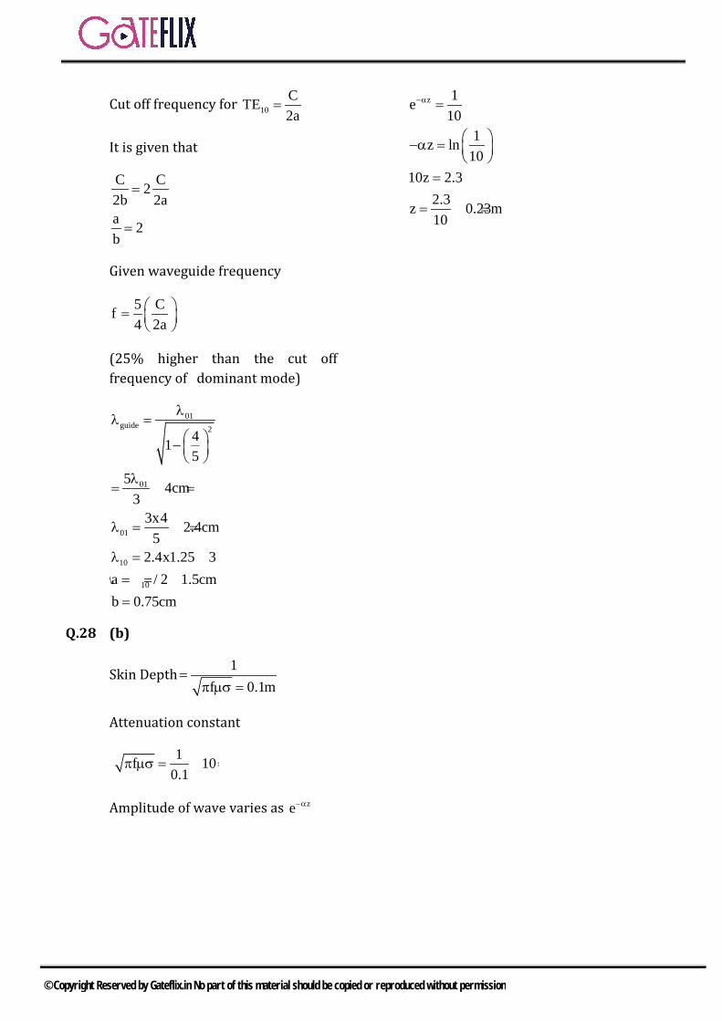
Cut off frequency for 10CTE2a
=
It is given that
C C22b 2aa 2b
=
=
Given waveguide frequency
5 Cf4 2a =
(25% higher than the cut off frequency of dominant mode)
01guide 2
01
01
10
10
415
5 4cm3
3x4 2.4cm5
2.4x1.25 3a / 2 1.5cmb 0.75cm
λλ =
−
λ= =
λ = =
λ = == λ ==
Q.28 (b)
Skin Depth 1f 0.1m
=π µσ =
Attenuation constant
1f 100.1
π µσ = =
Amplitude of wave varies as ze−α
z 1e10
1z ln10
10z 2.32.3z 0.23m10
−α =
−α =
=
= =
© Copyright Reserved by Gateflix.in No part of this material should be copied or reproduced without permission

An interface between free-space and transmission line that convert V/I waves to E/H waves and vice-versa is called an Antenna
The process of converting V/I waves into E/H waves is called as Radiation.
The process of converting E/H waves into V/I waves is called as Induction.
8.1 RADIATED POWER OF A HERTZIAN DIPOLE:
From Eθ and Hφ in the above equation,
Time averaged pointing vector= 1 E H2 θ φ
Power Radiated2
2 2r rms
1 dIE H W 80 I2 θ φ
= = = π λ ∫
The term 2
2 dl80 π λ is called Radiation
Resistance.
22
rdlR 80 = π λ
when applied for a more
practical centre fed-dipole of very short length dI.
(short dipole) 2
2r
dlR 20 = π λ
(short monopole) 2
2r
dlR 10 = π λ
8.2 RADIATION OF HALF-WAVE DIPOLE:
A more practical radiating device is a half wave dipole or opened out transmission line of length / 2λ corresponding to a frequency ‘f’.
All practical antennas are some or other modifications of the / 2λ dipole.
Fields of a dipole are expressed as
m
cos cos60I 2E
r sinθ
π θ =θ
8 ANTENNAS
© Copyright Reserved by Gateflix.in No part of this material should be copied or reproduced without permission
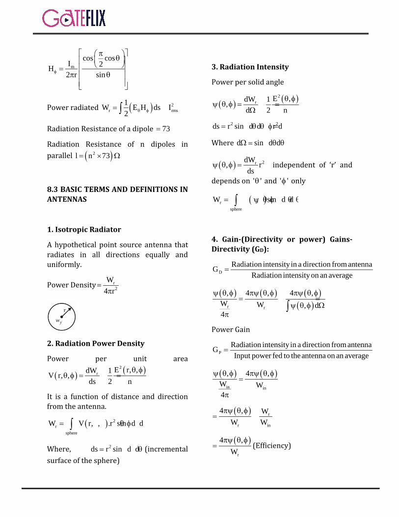
m
cos cosI 2H2 r sinφ
π θ =π θ
Power radiated ( ) 2r rms
1W E H ds I2 θ φ= =∫
Radiation Resistance of a dipole 73= Ω
Radiation Resistance of n dipoles in parallel ( )2l n 73= × Ω
8.3 BASIC TERMS AND DEFINITIONS IN ANTENNAS
1. Isotropic Radiator
A hypothetical point source antenna that radiates in all directions equally and uniformly.
Power Density r2
W4 r
=π
2. Radiation Power Density
Power per unit area
( ) ( )2r E r, ,dW 1V r, ,
ds 2 nθ φ
θ φ = =
It is a function of distance and direction from the antenna.
( ) 2r
sphere
W V r, , .r sin d d= θ φ θ θ φ∫
Where, 2ds r sin d d= θ θ φ (incremental surface of the sphere)
3. Radiation Intensity
Power per solid angle
( ) ( )2r E ,dW 1,
d 2 nθ φ
ψ θ φ = =Ω
2 2ds r sin d d r d= θ θ φ = Ω
Where d sin d dΩ = θ θ φ
( ) 2rdW, rds
ψ θ φ = = independent of ‘r’ and
depends on ' 'θ and ' 'φ only
( )rsphere
W , sin d d= ψ θ φ θ θ φ∫
4. Gain-(Directivity or power) Gains-Directivity (GD):
DRadiation intensity in a direction from antennaG
Radiation intensityon an average=
( ) ( ) ( )( )r r
, 4 , 4 ,W W , d4
ψ θ φ πψ θ φ πψ θ φ= =
ψ θ φ Ωπ
∫
Power Gain
PRadiation intensity in a direction from antennaGInput power fed to theantenna on an average
=
( ) ( )in in
, 4 ,W W4
ψ θ φ πψ θ φ=
π
( ) r
r in
4 , WW W
πψ θ φ= =
( )r
4 ,W
πψ θ φ= (Efficiency)
© Copyright Reserved by Gateflix.in No part of this material should be copied or reproduced without permission

Where r
in
WEffeciencyW
=
r r
r L r L
W RW W R R
= =+ +
WL = power losses
( )P DG Efficiency G=
( )DDirectivity D G maximum=
5. Radiation Resistance
6. Radiation pattern-Beam Angle
8. Effective Length
8. Effective Area
8.4 STUDY OF VARIOUS ANTENNA
8.4.1 YAGI-UDA ANTENNA:
• Active element is a folded dipole.• Reflector (5% greater in length
than folded dipole) and directors
(5% decrease in length than folded
dipole) are the parasitic elements.
• Single reflector exists but multiple
directors are possible.
• A unidirectional or single beam
radiation pattern is formed.
8.4.2 HELICAL ANTENNA:
• A simplest antenna to producecircularly polarized waves.
• It has two modes of operation:a) normal mode b)
Axial mode
• When h << λ it is normal mode asradiation is normal to the axis ofthe helix.
• Narrow band width and lossradiation efficiency limit the usageof this mode.
• When C is comparable to λ it isaxial mode with spacing of / 4λbetween the turns of the helix.
8.4.3 SLOT ANTENNA:
• A sheet of metal with length / 2λand width d when removed from itis called a slot antenna.
• The removed portion from themetal is called the complementaryslot antenna
• 2
c sZ .Z4η
=
Where Zc : impedance of complimentary slot
Zs : impedance of slot
• ( )cZ 73 j43= + Ω ,
( )sZ 363 j211= − Ω
8.4.4 LOG-PERIODIC ANTENNA:
• An array of dipoles whose lengths& spacings are varied withperiodicity that changes or repeatslogarithmically.
• nH nH nH
n n n
S L R 1S L R
= = =τ
• The value of τ lies between 0 and 1.
8.4.5 LONG-WIRE ANTENNA:
© Copyright Reserved by Gateflix.in No part of this material should be copied or reproduced without permission
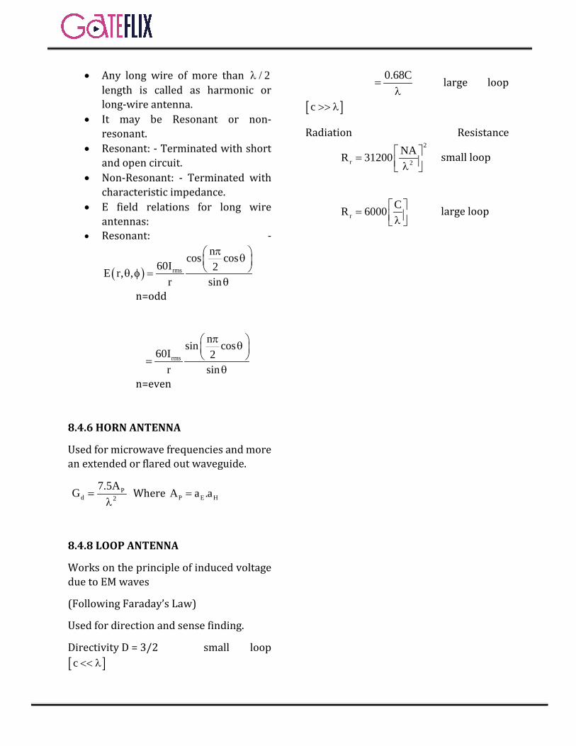
• Any long wire of more than / 2λ length is called as harmonic or long-wire antenna.
• It may be Resonant or non-resonant.
• Resonant: - Terminated with short and open circuit.
• Non-Resonant: - Terminated with characteristic impedance.
• E field relations for long wire antennas:
• Resonant: -
( ) rms
ncos cos60I 2E r, ,
r sin
π θ θ φ =
θ n=odd
rms
nsin cos60I 2
r sin
π θ =
θ n=even
8.4.6 HORN ANTENNA
Used for microwave frequencies and more an extended or flared out waveguide.
Pd 2
7.5AG =λ
Where P E HA a .a=
8.4.8 LOOP ANTENNA
Works on the principle of induced voltage due to EM waves
(Following Faraday’s Law)
Used for direction and sense finding.
Directivity D = 3/2 small loop [ ]c << λ
0.68C
=λ
large loop
[ ]c >> λ
Radiation Resistance
2
r 2
NAR 31200 = λ small loop
rCR 6000 = λ
large loop
© Copyright Reserved by Gateflix.in No part of this material should be copied or reproduced without permission
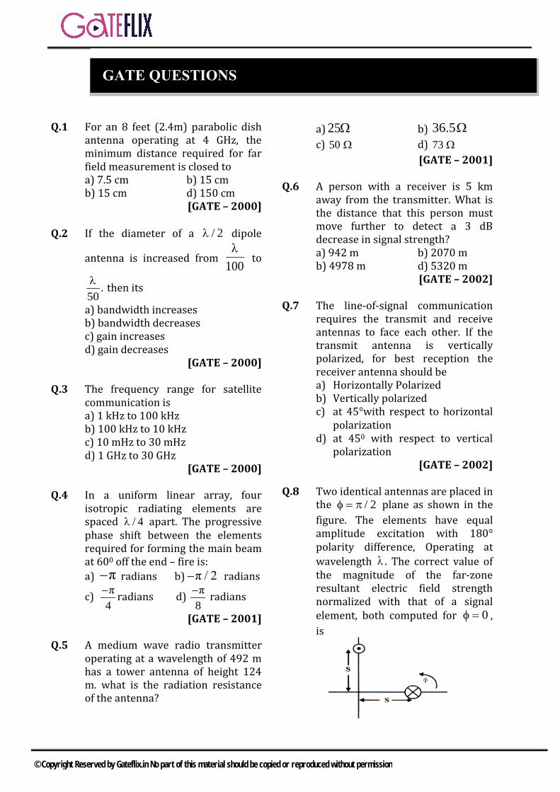
Q.1 For an 8 feet (2.4m) parabolic dish antenna operating at 4 GHz, the minimum distance required for far field measurement is closed to a) 7.5 cm b) 15 cmb) 15 cm d) 150 cm
[GATE – 2000]
Q.2 If the diameter of a / 2λ dipole
antenna is increased from 100λ
to
.50λ then its
a) bandwidth increasesb) bandwidth decreasesc) gain increasesd) gain decreases
[GATE – 2000]
Q.3 The frequency range for satellite communication is a) 1 kHz to 100 kHzb) 100 kHz to 10 kHzc) 10 mHz to 30 mHzd) 1 GHz to 30 GHz
[GATE – 2000]
Q.4 In a uniform linear array, four isotropic radiating elements are spaced / 4λ apart. The progressive phase shift between the elements required for forming the main beam at 600 off the end – fire is: a) –π radians b) –π / 2 radians
c) –π4
radians d) –π8
radians
[GATE – 2001]
Q.5 A medium wave radio transmitter operating at a wavelength of 492 m has a tower antenna of height 124 m. what is the radiation resistanceof the antenna?
a) 25Ω b) 36.5Ωc) 50 Ω d) 73 Ω
[GATE – 2001]
Q.6 A person with a receiver is 5 km away from the transmitter. What is the distance that this person must move further to detect a 3 dB decrease in signal strength? a) 942 m b) 2070 mb) 4978 m d) 5320 m
[GATE – 2002]
Q.7 The line-of-signal communication requires the transmit and receive antennas to face each other. If the transmit antenna is vertically polarized, for best reception the receiver antenna should be a) Horizontally Polarizedb) Vertically polarizedc) at 45 with respect to horizontal
polarizationd) at 450 with respect to vertical
polarization [GATE – 2002]
Q.8 Two identical antennas are placed in the / 2φ = π plane as shown in the figure. The elements have equal amplitude excitation with 180 polarity difference, Operating at wavelength λ . The correct value of the magnitude of the far-zone resultant electric field strength normalized with that of a signal element, both computed for 0φ = , is
GATE QUESTIONS
© Copyright Reserved by Gateflix.in No part of this material should be copied or reproduced without permission

a)2 s2cos π
λ b)
2 s2sin π λ
c)s2cos π
λ d)
s2sin π λ
[GATE – 2003]
Q.9 Consider a lossless antenna with a directive gain of + 6dB. If 1 mW of power is fed to it the total power radiated by the antenna will be a) 4 mW b) 1 mWd) 7 mW d) 1/4 mW
[GATE – 2004]
Q.10 Two identical and parallel dipole antennas are kept apart by a distance of / 4λ in the H-Plane.They are fed with equal currents but the right most antenna has a phase shift of + 900. The radiation pattern is given as
a) b)
c) d) [GATE – 2005]
Q.11 A mast antenna consisting of a 50 meter long vertical conductor operators over a perfectly conducting ground plane. It is base-fed at a frequency of 600 KHz. The radiation resistance of the antenna in Ohms is
a) 22
5π b)
2
5π
c)24
5π d) 220π
[GATE – 2006]
Q.12 A transmission line is feeding 1 watt of power to a horn antenna having a gain of 10 dB. The antenna is
matched to the transmission line. The total power radiated a) 10 Watts b) 1 Wattc) 0.1 Watt d) 0.01 Watt
[GATE – 2006]
Q.13 A 2λ dipole is kept horizontal at a
height of 0
2λ above a perfectly
conducting infinite ground plane. The radiation pattern in the plane of
(E Plane) Looks the dipole ( approximately as
a) b)
c) d) [GATE – 2007]
Q.14 At 20 GHz, the gain of a parabolic dish antenna of 1 meter diameter and 70% efficiency is a) 15 dB b) 25 dBb) 35 dB d) 45 dB
[GATE – 2008]
Q.15 For a Hertz dipole antenna, the half power Beam width (HPBW) in the E-plane is a) 3600 b) 1800
c) 900 d) 450
[GATE – 2008]
Q.16 The radiation pattern of an antenna in spherical co-ordinates is given by
4F( ) cos ,0 / 2θ = θ ≤ πThe directivity of the antenna is a)10 dB b) 12.6 dBc) 11.5 dB d) 18 dB
[GATE – 2012]
© Copyright Reserved by Gateflix.in No part of this material should be copied or reproduced without permission

Q.17 In spherical coordinates, let aθ. aϕ denote until vectors along the θ, 𝜙𝜙 directions.
E = θ100 sin θcos(ωt —βr)a V / m
r
$
and
H = 0.265 sin θcos(ωt —βr)a A / mr
φ
$
represent the electric and magnetic field components of the EM wave of large distances r from a dipole antenna, in free space. The average power (W) crossing the hemispherical shell located at r = 1km, 0 ≤ / θ ≤ π/2 is_______.
[GATE – 2014-1]
Q.18 For an antenna radiating in free space, the electric field at a distance of 1 km is found 12 to be 12 mV/m. Given that intrinsic impedance of the free space is 120πΩ, the magnitude of average power density due to this antenna at a distance of 2 km from the antenna (in nW/m2 ) is __________.
[GATE–2014-4]
Q.19 Match column A with column B.
column A column B. (1)Point electromagnetic source
(P)Highly directional
(2)Dish antenna (Q)End free (3)Yagi-Uda antenna (R)Isotropic
a) 1→P, 2→Q, 3→Rb) 1→R, 2→P, 3→Qc) 1→Q, 2→P, 3→Rd) 1→R, 2→Q, 3→P
[GATE–2014-4]
Q.20 Two half±wave dipole antennas placed as shown in the figure are excited with sinusoidally varying currents of frequency 3 MHz and phase shift of π/ 2 between them (the element at the origin leads in
phase). If the maximum radiated E- field at the point P in the x-y plane
occurs at an azimuthal angle of 60° the distance d (in meters) between the antennas is _________.
[GATE–2015-2]
Q.21 The directivity of an antenna array can be increased by adding more antenna elements, as a larger number of elements a) improves the radiation efficiency
b) increases the effective area ofthe antenna
c) results in a better impedancematching
d) allows more power to betransmitted by the antenna
[GATE–2015-3]
Q.22 Two loss1ess X-band horn antennas are separated by a distance of 200λ. The amplitude reflection coefficients at the terminals of the transmitting and receiving antennas are 0.15 and 0.18, respectively. The maximum directivities of the transmitting and receiving antennas (over the isotropic antenna) are 18 dB and 22 dB, respectively. Assuming that the input power in the lossless transmission line connected to the antenna is 2 W, and that the antennas are perfectly aligned and polarization matched, the power (in mW) delivered to the load at the receiver is_____.
[GATE–2016-1]
Q.23 The far-zone power density radiated by a helical antenna is approximated as:
© Copyright Reserved by Gateflix.in No part of this material should be copied or reproduced without permission

4rrad average 0 2
1W W a C cos θr
= ≈$r r
The radiated power density is symmetrical with respect to ∅ and exists only in the upper hemisphere:
π0 θ ;0 2π;2
≤ ≤ ≤∅ ≤ Co is a
constant. The power radiated by the antenna (in watts) and the maximum directivity of the antenna, respectively, are a) 1.5CO, 10dB b)1.256Co, 10Db c) 1.256Co, 12dB d) 1.5CO, 12dB
[GATE–2016-1]
Q.24 A radar operating at 5 GHz uses a common antenna for transmission and reception. The antenna has a gain of 150 and is aligned for maximum directional radiation and reception to a target 1 km away having radar cross-section of 3 m2. If it transmits 100 kW, then the received power (in µW) is ______.
[GATE–2016-3]
Q.25 Consider a wireless communication link between a transmitter and a receiver located in free space, with finite and strictly positive capacity. If the effective areas of the transmitter and the receiver antennas, and the distance between them are all doubled, and everything else remains unchanged, the maximum capacity of the wireless link
a) increases by a factor of 2b) decrease by a factor 2c) remains unchanged
d) decreases by a factor of 2
[GATE–2017-1]
© Copyright Reserved by Gateflix.in No part of this material should be copied or reproduced without permission

1 2 3 4 5 6 7 8 9 10 11 12 13 14 (d) (b) (d) (c) (b) (b) (b) (d) (b) (a) (a) (b) (b) (d) 15 16 17 18 19 20 21 22 23 24 25 (c) (a) 55.5 47.5 (b) 50 (b) 3 (b) 2 (c)
ANSWER KEY:
© Copyright Reserved by Gateflix.in No part of this material should be copied or reproduced without permission

Q.1 (d) 22ld
λ=
8
9
3 10λ 7.54 10×
= =×
2 2.4 2.4d 1.536m7.5
× ×= =
Q.2 (b)
Q.3 (d) The frequency range for satellite communication is 1GHz to 30GHz.
Q.4 (c) Ψ βd cosθ α= + For an array to be end fire Ψ = 0 0=βdcosθ+α α βd= −
( )Ψ βd cosθ 1⇒ = −
( )2π λΨ cos 60° 1λ 4
⇒ = × −
π 1 πλ 2 4
= × − = −
radians
Q.5 (b) λ 492 123 L4 4= = ;
∴ It is a quarter wave monopole antenna So, aR 36.5Ω=
Q.6 (b)
Signal strength 2
p4πR
=
( )1 2pp
4π 5000=
( )2 2pp
4π x=
Given 1
2
p 1p 2
= (3dB decrease)
25000 1x 2
⇒ = x 5000 2⇒ =
Required distance 5000 2 5000= − 2071m=
Q.7 (b)
Q.8 (d)
Normalized array factor Ψ2 cos2
=
Ψ βdsinθcodΦ δ= +
θ 90°,d 2s= = Φ 45°,δ 180°= =
Ψ2 cos2
⇒
βdsinθcodΦ δ2cos2
+ = 2π 180°2cos 2scos45°λ.2 2 = +
πs2cos 90°λ
= + πs2sinλ
=
Q.9 (b) When an antenna is lossless then the antenna efficiency is 100% .In such case whole of the power fed to antenna is radiated in the form of radiation. Therefore if power fed to antenna is 1 m W.
EXPLANATIONS
© Copyright Reserved by Gateflix.in No part of this material should be copied or reproduced without permission
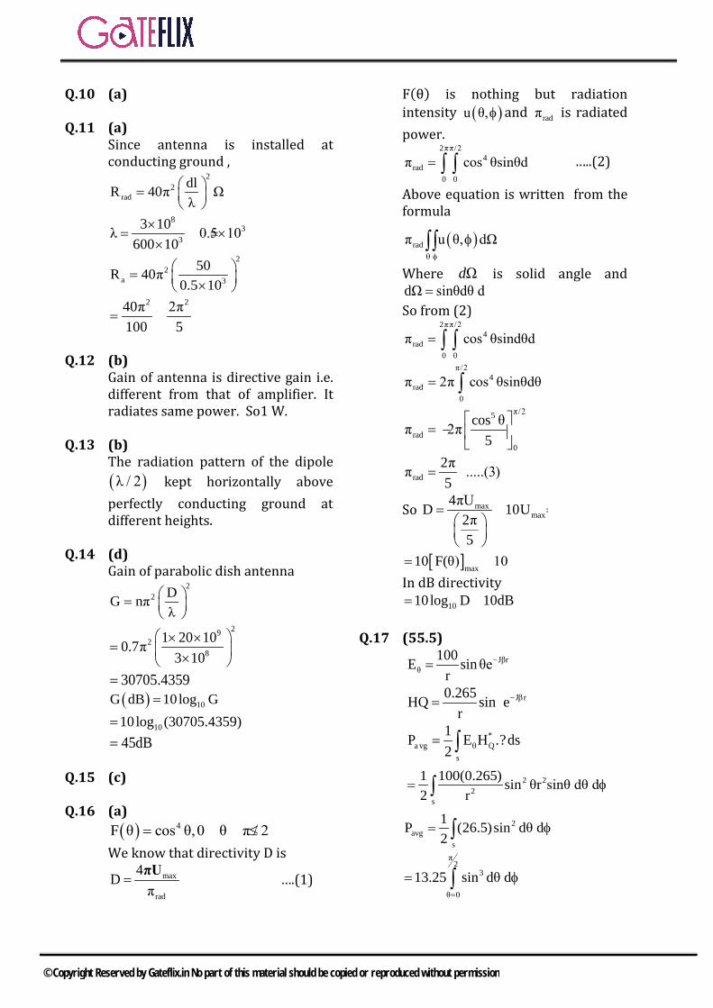
Q.10 (a)
Q.11 (a) Since antenna is installed at conducting ground ,
22
raddlR 40π Ωλ
=
83
3
3 10λ 0.5 10600 10×
= = ××
22
a 3
50R 40π0.5 10
= × 2 240π 2π
100 5= =
Q.12 (b) Gain of antenna is directive gain i.e. different from that of amplifier. It radiates same power. So1 W.
Q.13 (b) The radiation pattern of the dipole ( )λ / 2 kept horizontally aboveperfectly conducting ground at different heights.
Q.14 (d) Gain of parabolic dish antenna
22 DG nπ
λ =
292
8
1 20 100.7π3 10
× ×= ×
30705.4359=( ) 10G dB 10log G=
1010 log (30705.4359)=45dB=
Q.15 (c)
Q.16 (a) ( ) 4F θ cos θ,0 θ π / 2= ≤ ≤
We know that directivity D is max
rad
4Dπ
=πU
….(1)
F(θ) is nothing but radiation intensity ( )u θ,φ and radπ is radiatedpower.
2ππ/24
r d0 0
aπ cos θsinθd= φ∫ ∫ …..(2)
Above equation is written from the formula
( )radπ u θ, dΩθ φ
φ∫∫
Where Ωd is solid angle and dΩ sinθdθ d= φ So from (2)
2ππ/24
r d0 0
aπ cos θsindθd= φ∫ ∫π/2
4rad
0
π 2π cos θsinθdθ= ∫π/25
rad0
cos θπ 2π5
= −
rad2ππ .....(3)5
=
So maxmax
4πUD 10U2π5
= =
[ ]max10 F(θ) 10= =
In dB directivity 1010 log D 10dB= =
Q.17 (55.5)
Jβrθ
100E sin θer
−=
J r0.265HQ sin er
− β= θ
*a vg Q
s
1P E H .?ds2 θ= ∫
2 22
s
100(0.265) sin θr sinθ dθ dr
12
φ= ∫
2avg
s
1 (26.5)sin d d2
P θ φ= ∫
π2
3
θ 0
13 sin. 5 θ2 d d=
= φ∫
© Copyright Reserved by Gateflix.in No part of this material should be copied or reproduced without permission

P= 55.5w
Q.18 (47.7) Electric field of an antenna is
0θ 2 3
ηΙ dI Jβ 1 JE sinθ r r βr4π
Radiation inductive Electrostanicfield field field
=
↓ ↓ ↓
1Eαr
∴
1 22
2 1
E r E 6mv / mE r
= ⇒ =
2 821 E 1 36 10P 47.7nw / m
2 η 2 120π
−×= = =
Q.19 (b) 1. Point electromagnetic source, canradiate fields in all directions equally, so isotropic. 2. Dish antenna →highly directional
3. Yagi — uda antenna →End fire
Figure: Yagi — uda antenna
Q.20 (50) ψ δ βdcosθ= + For maximum field,
8
6
3 10ψ 0 λ 100m3 10×
= = =×
δ βdcosθ 0+ = π 2π dcos60 02 λ
− + =
π 2π 1(d)2 100 2=
d = 50 m
Q.21 (b)
2
4πD Aeλ
=
D Ae↑→ ↑
Q.22 (3)
Q.23 (b) π 2π2
2rad rad
θ 0 0
P W r sinθdθd= ∅=
= ∅∫ ∫
π 2π24 20
2β 0 0
C cos ωr sinωdθdr= ∅=
= ∅∫ ∫π
2θ 2
0 0 00
cos 2πC .2π C 1.256C5 5
−= × = =
Max. directivity 2rad
rad
max(W ) 4πrP
×=
02 2
0
C4πr 4πr 10
1.256C 1.256= × = =
Max. directivity indB=10log10=10dB
Q.24 (2)
Q.25 (c)
20
SC Blog 1N B
= +
Where,
( )
( )
t t er2
1 t ere2 2
t er e er et 2 22 2
t er e2 2
P G AS4 r
P A 4S . A t4 r
P A A t 4A A tP4 rr
P A A t SA r
=π
π=
π λ
= =λλ
= =
Channel capacity remain same.
Channel capacity remains same.
© Copyright Reserved by Gateflix.in No part of this material should be copied or reproduced without permission

Q.1 Which of the following statement regarding electric flux is true? 1. Electric flux begins on positive
charges and terminates onnegative charges.
2. Flux is in the same direction as
the electric field E
3. Flux density is proportional to
the magnitude of E
4. In the SI system of units, totalflux emanating from a charge ofQ(C) is Q(C).
A single line will emanate from 1 C of charge. a) 1 only b) 1 & 2 onlyc) 1, 2 & 3 only d) 1, 2, 3 & 4
Q.2 Two concentric spherical shells carry equal and opposite uniformly distributed charges over their surfaces as shown in the figure. The electric field on the surface of the inner shell will be
a) zero b) 2
0
Q
4 R
c) 2
0
Q
8 Rd)
2
0
Q
16 R
Q.3 Joule/Coulomb is the unit of a) Electric field potentialb) Electric flux densityc) Charged) None of the above
Q.4 The electric potential due to an electric dipole of length L at a point distance r away from it will be doubled if the a) length L of the dipole is doubledb) r is doubledc) r is halvedd) L is halved
Q.5 The force between two charged particles is given by,
221
0 r
4
1F
, where the symbols
have their usual meanings. The dimensions of 0 in free space in SI system are: a) M-1 L-3 T6 A4 b) M-1 L-3 T4 A2
c) ML-3 T4 A3 d) M-1 L-3 T2
Q.6 The energy spent in moving a charge of 10 coulomb from one point ‘a’ to another point ‘b’ is 50 joules. The potential difference between points ‘a’ and ‘b’ is a) 2 volts b) 5 voltsc) 10 volts d) 100 volts
Q.7 P is a point at a large distance from the centre O of a short dipole formed by two point charges all lying on a horizontal plane. If is the angle between OP and the dipole axis, then , component of the E-field at P is
a) given by sin b) given by cos c) given by tan d) independent of
Q.8 Two equal positive point charges are
placed along X-axis at + X1 and –X1 respectively. The electric field vector at a point P on the positive Y axis will be directed a) in the +X directionb) in the –X directionc) in the +Y directiond) in the –Y direction
Q.9) Two concentric spherical conducting shells are held at two different potentials. Their centre coincides with the origin of a spherical (r, )
0R
a
a2R
9 ASSIGNMENT QUESTIONS
© Copyright Reserved by Gateflix.in No part of this material should be copied or reproduced without permission

coordinate system. Which one of the following gives the correct nature of the field in the angular gap region? a) It is purely radial and
independent of the coordinates (r,,)
b) It is purely radial, independentof (, ) and varies as r-2
c) The field lines are the like thelatitude of the Earth anddepend on (r, ) but not on
d) The field lines are radial andindependent of (, ) but variesas r-1
Q.10 Which one of the following pairs is NOT correctly matched?
a) s v
Gauss 'sTheorem: D ds Ddv
b) v
Gauss 's Law: D ds dv
c) mdCoulomb's Law:V
dt
d) l s
Stoke 'sTheorem : d l ds
Q.11 When a dielectric is placed in an electric field, the electric flux density D, electric field intensity E and polarization P are related as
a)0D E P b)
0D E P
c) 0D E P d)0D E P
Q.12 A, B and C are three parallel plate condensers with similar surface area of plates and similar separation. A contains air as dielectric, B contains glass as dielectric and C contains polythene. If the electric field intensities in air, glass and polythene are respectively E1, E2 and E3 then (assume that the plates are filled with the given dielectrics) a) E1 = E2 = E3 b) E1 = E2 > E3
c) E1 > E2 < E3 d) E1 < E2 > E3
Q.13 Maxwell’s divergence equation for the electric field is
a)0
E
b) 0
E2
c)0
E
d) 0
E2
Q.14 The dipole moment per unit volume as a function of E in the case of an insulator is given by (symbols have the usual meanings)
a) 0 rP E 1 b) 0P E
c) 0 r
EP
d)
0 r
EP
1
Q.15 A parallel plate capacitor of plate area A and plate separation ‘t’ has a capacity C. If a metallic plate of area A and of negligible thickness is introduced in the capacitor at a
distance 2
tfrom either of the two
plates, as shown in the given figure, then the capacity of the capacitor will become
a) C
2b) C
c) 2C d) 4C
Q.16 An infinite plane Z = 10 m carries a uniformly distributed charge of density 2nC/m2. The electric field intensity at the origin is a) 0.2 azn V/m b) 2 azn V/mc) -2 azn V/m d) -36 az V/m
Q.17 If an isolated conducting sphere in
air has radius = 04
1
its
capacitance will be a) zero b) 1Fc) 4 F d ) 0F
Q.18 Which one of the following is the Poisson’s equation for a linear and isotropic but inhomogeneous medium?
a) 2V / b) V
© Copyright Reserved by Gateflix.in No part of this material should be copied or reproduced without permission

c) V d) 2V /
Q.19 The displacement flux density at a point on the surface of a perfect
conductor is x zD 2 a 3a C/m2
and is pointing away from the surface. The surface charge density at that point (C/m2) will be a) 2 b) -2c) 4 d) -4
Q.20 Charge needed within a unit sphere centered at the origin for producing
a potential field.5
0
6rV ,for r 1
is
a) 12C b) 60Cc) 120C d) 180C
Q.21 The equation 0 J is known as a) Poisson’s equationb) Laplace equationc) Continuity equationd) Maxwell equation
Q.22 The dimension of flux density is a) MT-1 Q-1 b) MT-2Q-2
c) MT1Q1 d) MT-1Q-2
Q.23 The energy stored per unit volume in an electric field (with usual notations) is given by
a) 21H
2 b)
1H
2
c) 21E
2 d) 2E
Q.24 A positive charge of Q coulomb is located at point A (0,0,3) and a negative charge of magnitude Q coulomb is located at point B (0,0,-3). The electric field intensity at point C (4,0,0) is in the a) negative x-directionb) negative z-directionc) positive x-directiond) positive z-direction
Q.25 The force between two point charges of 1 nC each with a 1 mm separation in air is
a) -39 10 N b) -69 10 N
c) -99 10 N d) -129 10 N
Q.26 Consider the following statements: A parallel plane capacitor is filled with a dielectric of relative permittivity
1r and connected to a
d.c. voltage of V volts. If the dielectric is changed to another with relative permittivity
2 1r r2 ,
keeping the voltage constant, then 1. the electric field intensity within
the capacitor doubles.2. the displacement flux density D
doubles.3. the charge Q on the plates is
reduced to half.4. the energy stored in the
capacitor is doubled.Select the correct answer using the codes given below: a) 1 and 2 b) 2 and 3c) 2 and 4 d) 3 and 4
Q.27 The resistivity of the wire material can be expressed in terms of LMTI system of dimensional parameter as a) ML2 T-2 I-2 b) ML2 T-3 I-2
c) ML3 T-3 I-2 d) ML3 T-2 I-2
Q.28 An electronic charge Q is placed in a dielectric medium. Which of the following quantities are independent of the dielectric constant of the medium? a) Electric potential V and Electric
field intensity Eb) Displacement density D and
Displacement c) Electric field intensity E and
Displacement density Dd) Electric potential V and
Displacement
© Copyright Reserved by Gateflix.in No part of this material should be copied or reproduced without permission
Q.29) Two coaxial cylindrical sheets of charge are present in free space
2
s 5C / m at r=2m & 2
s 2C / m
at r=4m. The displacement flux
density D at r = 3 m is
a) 2rD 5a C / m b) 2
r
2D a C / m
3
c) 2r
10D a C / m
3 d) 2
r
18D a C / m
3
Q.30 An electric potential field is produced in air by point charges 1 C and 4 C located at (-2,1,5) and (1,3,-1) respectively. The energy stored in the field is a) 2.57 mJ b) 5.14 mJc) 10.28 mJ d) 12.50 mJ
Q.31 Which one of the following potentials does NOT satisfy Laplace’s Equation? a) V 10xy b) V r cos
c) 10
Vr
d) V cos 10
Q.32 Laplacian of a scalar function V is a) Gradient of Vb) Divergence of Vc) Gradient of the gradient of Vd) Divergence of the gradient of V
Q.33 An infinitely long uniform charge of density 30 nC/m is located at y = 3, z = 5. The field intensity at (0, 6, 1) is E = 64. 7ay – 86.3az V/m. What is the field intensity at (5,6,1)?
a) E b) 2
2 2 2
6E
5 6 1
c)
1/22
2 2 2
6E
5 6 1
d)
1/22 2 2
2
5 6 1E
6
Q.34 An infinitely long line charge of uniform charge density 0 C/m is situated parallel to and at a distance from the grounded infinite plane conductor. This field problem can be
solved by which one of the following? a) By conformal transformationb) By method of imagesc) By Laplace’s equationd) By Poisson’s equation
Q.35 The electric field lines and equipotential lines a) are parallel to each otherb) are one and the samec) cut each other orthogonallyd) can be inclined to each other at
any angle
Q.36 Curl curl A is given by
a) 2A b) 2A A
c) 2A d) A A
Q.37 If a charge of one coulomb is to be brought to a distance of one meter from a charge of 2 coulombs, then the work required is
a) 0
1N m
2
b)
0
1N m
4
c) 02 N m d) 04 N m
Q.38 Ohm’s law in point form in field theory can be expressed as
a) V RI b) E
j
c) J E
d) l
RA
Q.39 The force between a charge q and a grounded infinite conducting plane kept at a distance d from it is given by
a) 2
0
q
4 db)
2
2
0
q
4 d
c) 2
0
q
16 dd)
2
2
0
q
16 d
Q.40 The magnetic field intensity (in amperes/meter) at the centre of a
© Copyright Reserved by Gateflix.in No part of this material should be copied or reproduced without permission
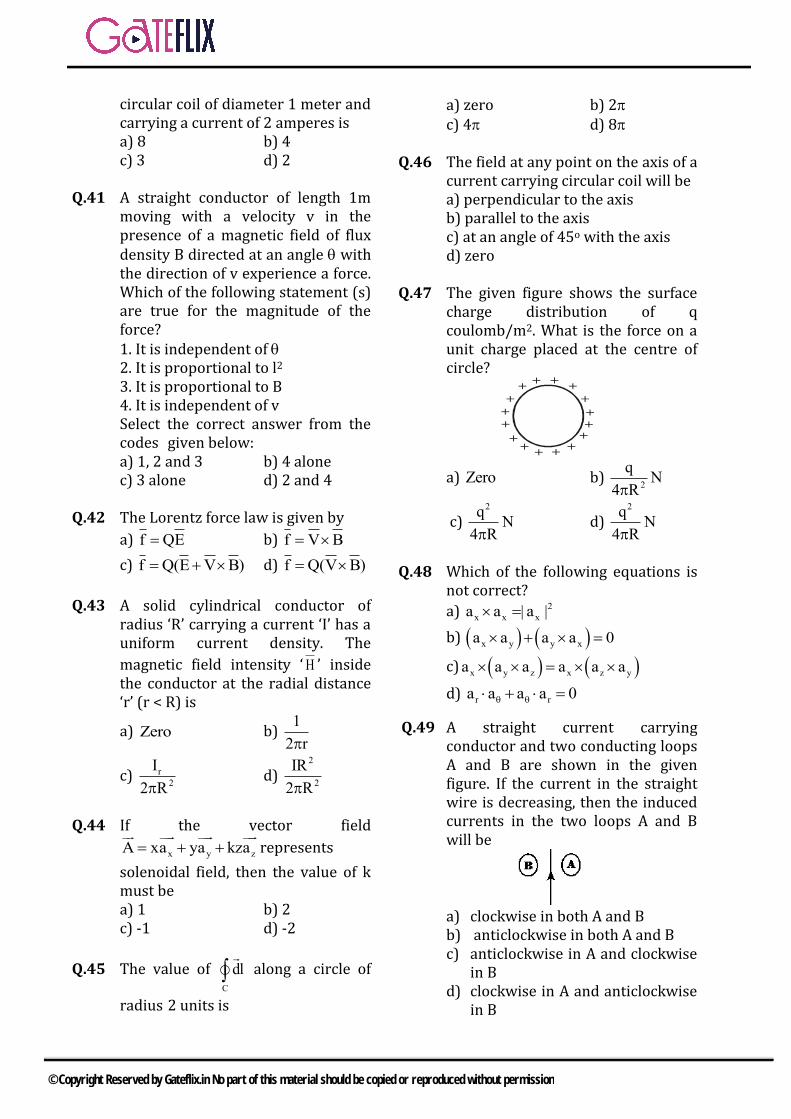
circular coil of diameter 1 meter and carrying a current of 2 amperes is a) 8 b) 4c) 3 d) 2
Q.41 A straight conductor of length 1m moving with a velocity v in the presence of a magnetic field of flux density B directed at an angle with the direction of v experience a force. Which of the following statement (s) are true for the magnitude of the force? 1. It is independent of 2. It is proportional to l2
3. It is proportional to B4. It is independent of vSelect the correct answer from the codes given below: a) 1, 2 and 3 b) 4 alonec) 3 alone d) 2 and 4
Q.42 The Lorentz force law is given by
a) f QE b) f V B
c) f Q(E V B) d) f Q(V B)
Q.43 A solid cylindrical conductor of radius ‘R’ carrying a current ‘I’ has a uniform current density. The
magnetic field intensity ‘ H ’ inside the conductor at the radial distance ‘r’ (r < R) is
a) Zero b) 1
2 r
c) r
2
I
2 Rd)
2
2
IR
2 R
Q.44 If the vector field
x y zA xa ya kza
represents
solenoidal field, then the value of k must be a) 1 b) 2c) -1 d) -2
Q.45 The value of C
dl
along a circle of
radius 2 units is
a) zero b) 2c) 4 d) 8
Q.46 The field at any point on the axis of a current carrying circular coil will be a) perpendicular to the axisb) parallel to the axisc) at an angle of 45o with the axisd) zero
Q.47 The given figure shows the surface charge distribution of q coulomb/m2. What is the force on a unit charge placed at the centre of circle?
+
+
++
++
+
+
+
+
++
+ +
+ +
a) Zero b) 2
qN
4 R
c) 2q
N4 R
d) 2q
N4 R
Q.48 Which of the following equations is not correct?
a) 2
x x xa a | a |
b) x y y xa a a a 0
c) x y z x z ya a a a a a
d) r ra a a a 0
Q.49 A straight current carrying conductor and two conducting loops A and B are shown in the given figure. If the current in the straight wire is decreasing, then the induced currents in the two loops A and B will be
a) clockwise in both A and Bb) anticlockwise in both A and Bc) anticlockwise in A and clockwise
in Bd) clockwise in A and anticlockwise
in B
© Copyright Reserved by Gateflix.in No part of this material should be copied or reproduced without permission

Q.50 The region 0z is a perfect conductor. On its surface at the
origin, the surface current density K
is m/A)a6a5( yx . If the region z >
0 were free space, then the magnetic
field intensity H in A/m, at the origin would be
a) H 0
b) x yH 5a 6a
c) yx aaH 56
d) x yH 6a 5a
Q.51 x
x
2 E a
3 E 2a
The electric field
across an interface is shown in the figure. The surface charge density (in coulomb/m2) on the interface is a) 04 b) 03
c) 03 d) 04
Q.52 The polarization of a dielectric material is given by
a)rP E b)
rP ( 1)E
c) o rE E 1 d) r oP 1
Q.53 If the charge on each of the capacitors in the given figure is 4500 C, what is the total capacitance (in F), assuming that the voltage distribution across C1, C2, C3 is in the ratio of 2:3:4?
a) 325 b) 11.1c) 22.2 d) 33.3
Q.54 Consider the following statements regarding field boundary conditions: 1. The tangential component of
electric field is continuous acrossthe boundary between twodielectrics.
2. The tangential component ofelectric field at a dielectricconductor boundary is non-zero.
3. The discontinuity in the normalcomponent of flux density at adielectric conductor boundary isequal to the surface chargedensity on the conductor.
4. The normal component of theflux-density is continuous acrossthe charge-free boundarybetween two dielectrics.
Which of these statements are currect a) 1, 2 and 3 are correctb) 2, 3 and 4 are correctc) 1, 2 and 4 are correctd) 1, 3 and 4 are correct
Q.55 The infinite parallel metal plates are charged with equal surface charge density of the same polarity. The electric field in the gap between the plates is a) the same as that produced by
one plateb) double of the field produced by
one plate.c) dependent on coordinates of
field pointd) zero
Q.56 Two positive charges, Q Coulombs each, are placed at points (0, 0, 0) and (2, 2, 0) while two negative charges, Q coulombs each in magnitude, are placed at points (0, 2, 0) and (2, 0, 0). The electric fieldintensity at the point (1,1,0) is
a) zero b) 0
Q
8
c) 0
Q
4d)
0
Q
16
Q.57 Consider the following statements associate with the basic electrostatic properties of ideal conductors: 1. The resultant field inside is zero.
© Copyright Reserved by Gateflix.in No part of this material should be copied or reproduced without permission

2. The net charge density in theinterior is zero.
3. Any net charge resides on thesurface
4. The surface is always equipotential.
5. The field just outside is zero.Which of these statements are currect a) 1, 2, 3 and 4 are correctb) 3, 4 and 5 are correctc) 1, 2 and 3 are correctd) 2 and 3 are correct
Q.58) A capacitor is made up of two concentric spherical shells. The radii of the inner and outer shells are R1 and R2 respectively and is the permittivity of the medium between the shells. The capacitance of the capacitor is given by
a) 1 2
1 1 1
4 R R
b) 1 2
1 1 1
4 R R
c)
1 2
1 2
R R4
R R
d) 1 2
2 1
R R4
R R
Q.59 In a hundred-turn coil, if the flux through each turn is (t3-2t)m Wb, the magnitude of the induced emf in the coil at a time of 4s is a) 46 mV b) 56 mVc) 4.6 V d) 5.6 V
Q.60 A coil of resistance of 5 and inductance 0.4 H is connected to a 50 V d.c. supply. The energy stored in the field is a) 10 joules b) 20 joulesc) 40 joules d) 80 joules
Q.61 For an elliptically polarzed wave incident on the interface of a
dielectric at the Brewster angle, the reflected wave will be a) elliptically polarizedb) linearly polarizedc) right circularly polarizedd) left circularly polarized
Q.62 If the current element represented
by 4
y4 10 a Am is placed in a
magnetic field of
x
5 ˆH a A / m the
force on the current element is
a)
z2a mN b)
z2a mN
c)
z2a N d)
z2a N
Q.63 In an electrodynamometer, a moving coil has an area A, turn N and carries a current I producing a magnetic flux B. The torque on the moving coil is proportional to a) I b) I2
c) B.I2 d) A.N.B.I2
Q.64 The three values of a one-dimensional potential function shown in the given figure and satisfying Laplace’s equation are related as
1 2 3
d 2d
a) 3 12
2
3
b) 1 3
2
2
3
c) 1 32
2 2
3
d) 1 3
2
3
2
Q.65 The skin depth () due to RF current is equal to ( = angular frequency, = permeability and = conductivity) .
a) 2
b)
2
c)
1/2
2
d)2
Q.66 The electric field of an electromagnetic wave at a point in
© Copyright Reserved by Gateflix.in No part of this material should be copied or reproduced without permission

free space is in the positive Y direction and the magnetic field is in the negative X direction. The direction of power flow will be in the a) + X direction b) +Y directionc) +Z direction d) –Z direction
Q.67 The electric field vector E of a wave in free space (o, o) is given by
zE y Acos t
c
Its magnetic
vector H will be given by
a) z
H y Asin tc
b) z
H z Acos tc
c) o
o
zH x j Acos t
c
d) o
o
zH x j Asin t
c
Q.68 What is the phase velocity of plane wave in a good conductor?
a) f b) f
c) f
d)
f2
Q.69 An electromagnetic plane wave propagates in a dielectric medium characterized by r = 4 and r = 1. The phase velocity of the wave will be
a) 80.75 10 m / s b) 81.5 10 m / s
c) 83 10 m / s d) 86 10 m / s
Q.70 If H = 0.2cos (t - x)az A/m is the magnetic field of a wave in free space, then the average power passing through a circle of radius 5 cm in the x= 1 plane will be=approximately a) 30mW b) 60mW
c) 120mW d) 150mW
Q.71 The depth of penetration or skin depth for an electromagnetic field at a frequency ‘f’ in a conductor of resistivity and permeability is a) inversely proportional to and f
& directly proportional to b) directly proportional to and
inversely proportional to f & c) directly proportional to f and
inversely proportional to & d) inversely proportional to and
and directly proportional to f.
Q.72 When a plane wave is incident normally from dielectric ‘1’ ( 1o , )
onto dielectric ‘2’ ( 2o , ), the
electric field of the transmitted wave is -2 times the electric field of the reflected wave. The ratio
2
1
is
a) 0.5 b) 1c) 2 d) 4
Q.73 If, for the transmission of a parallel polarized wave from a dielectric medium of permittivity 1 into a
dielectric medium of permittivity
2 there exists a value of the angle
of incidence p for which the
reflection coefficient is zero, then
a) 1p
2
tan h
b) 1p
2
tan
c) 2p
1
tan
d) 2p
1
tan h
Q.74 For electromagnetic wave propagation in free space, the free space is defined as
a) 0, 1, 1,P 0,J 0
b) 0, 1, 1,P 0,J 0
c) 0, 1, 1,P 0,J 0
d) 0, 1, 1,P 0,J 0
© Copyright Reserved by Gateflix.in No part of this material should be copied or reproduced without permission
Q.75 The Poynting vector HEP has the dimensions of a) Power/unit areab) Voltsc) Powerd) Volt/unit length
Q.76 Consider the following statements regarding a plane wave propagating through free space: The direction of field 1) ‘E’ is perpendicular to the
direction of propagation2) ‘H’ is perpendicular to the
direction of propagation3) ‘E’ is perpendicular to the
direction of field ‘H’Which of these statements are correct ? a) 1 and 2 b) 2 and 3c) 1 and 3 d) 1, 2 and 3
Q.77 If the velocity of electromagnetic
wave in free space is 83 10 m/s, the velocity in a medium with r of 4.5
and r of 2 would be
a) 81 10 / m s b)
83 10 / m s
c) 89 10 / m s d) sm /1027 8
Q.78 If 8
xH 0.1 sin(10 t y)a A/m for a
plane wave propagating in free space, then the time average Poynting vector is
a) 2 2y(0.6 sin y)a W / m
b) /a0.6- 2^
y mW
c) 2x1.2 a W / m
d) 2y-1.2 a W / m
Q.79 In a uniform plane wave, the value of
H
Eis
a)
b)
c) 1 d)
Q.80 Which one of the following statements is NOT correct for a
plane wave with ^
0.1x 6z
AH 0.5e cos(10 t 2x)a
m
a) The wave frequency is 106 r.p.s.b) The wavelength is 3.14 mc) The wave travels along + x-
directiond) The wave is polarized in the z-
direction
Q.81 What is the value of standing wave Ratio (SWR) in free space for
transmission coefficient 3
1
a) 3
2b) 5.0
c) 0.4 d) 0.2
Q.82 A ray is incident on the boundary of a dielectric medium of dielectric constant 1 with another perfect
dielectric medium of dielectric constant 2 . The incident ray makes
an angle of with the normal to the boundary surface. The ray transmitted into the other medium makes an angle of 2 with the normal. If 1 =2 2 and 1=60o,
which one of the following is correct? a) 2 = 45o b) 2=sin-10.433 c) 2=sin-1 0.612 d) There will be no transmitted
wave
Q.83 The electric field of a wave propagation through a lossless medium (0, 810) is
8yE 10cos(6 10 t x)a What is
the phase constant of the wave ? a) 2 rad/m b) 9 rad/mc) 18 rad/m d) 81 rad/m
Q.84 Which one of the followig gives the values of the attenuation factor
112
© Copyright Reserved by Gateflix.in No part of this material should be copied or reproduced without permission

and phase shift factor for a wave propagated in a good conductor having /() >> 1 ?
a) ;2
b) / ; /
c) /
;2
d) 20;
Q.85 Consider the two fields, E = 120cos(106 t - x) ay V/m and H = A cos(106 t - x) az A/m The values of A and which will satisfy the Maxwell’s equation in a linear isotropic, homogenous, loss-less medium with r = 8 and r = 2 will be A (in A/m) (in rad/m) a) 1 0.0105 b) 1 0.042 c) 2 0.0105 d) 2 0.042
Q.86 The velocity of a traveling electromagnetic wave in free space is given by
a) 0 0 b) 0 0
c) 0 0
1
d)
0 0
1
Q.87 The equation of a plane wave may by written as (with usual symbols)
a) 2 2
y y
2 2
E E1
t x
b)
2 2y
2 2
E 1 E
x t
c) 2 2
y
2 2
E E
t x
d)
2 2y
2 2
E E
t x
Q.88 For time-varying electromagnetic fields with electric and magnetic field given by |E| & |H| respectively the rate of energy flow per unit area has a magnitude given by a) |E| |H| cos b) |E| |H| sin
c) (|E|+|H|)sin d)(|E|-|H|)cos
Q.89 The E field of a plane electromagnetic wave traveling in a non- magnetic non conducting medium is given by
9xE a 5cos(10 t 30Z)
. What is the
dielectric constant of the medium ? a) 30 b) 10c) 9 d) 81
Q.90 The expression for B , given that in the free space
8
xE 15cos 6 10 t 2 z i V / m is
a) 8 8
y5 10 cos 6 10 t 2 z i
b) 8 8
x90 10 sin 6 10 t 2 z i
c) 8 8
y45 10 sin 6 10 t 2 z i
d) 8 8
y5 10 cos 6 10 t 2 z i
8
zsin 6 10 t 2 z i
Q.91 A uniform plane electromagnetic wave with electric component E = Em cos (t - px) propagates in vacuum along the positive x-direction. The mean Poynting Vector is given by
a) m
2 2
0 c E1
2
b)
m
2 2
0c E1
2
c) 2
0 mc E1
2
d)
m
2
0 c E1
2
Q.92 In a lossless medium the intrinsic impedance =60 and r = 1. What is the value of the dielectric constant r? a) 2 b) 1c) 4 d) 8
Q.93 If the E field in a plane electromagnetic wave traveling along the z-axis is given by
x y x yE a a f ωt βz a a f ωt βz
The H field associated with the wave is (z0 is the characteristic impedance)
© Copyright Reserved by Gateflix.in No part of this material should be copied or reproduced without permission

a) x y 0a a f t z / z
x y 0a a f t z / z
b) x y 0a a f t z / z
x y 0a a f t z / z
c) y x 0a a f t z / z
y xa a f t z / z
d) x y 0a a f t z / z
y xa a f t z / z
Q.94 If the electric field xt ate1.0E
and 04 , then the
displacement current crossing an area of 0.1 m2 at t = 0 will be a) zero b)
004.0
c) 04.0 d) 04
Q.95 Match List I with List II and select the correct answer using the codes given below the lists:
List I A. V D
B. V Dt
C. cV H J
D.B
V Et
List II 1. Ampere’s Law2. Dauss’s Law3. Fraday’s Law4. Continuity equationCodes:
A B C D a) 4 2 1 3b) 2 4 1 3 c) 4 2 3 1d) 2 4 3 1
Q.96 If the static magnetic flux density is
B , then
a) 0 B b) 0 B
c) JB d) JB
Q.97 Match List I with List II and select the correct answer using the codes given below the lists: List I (Law/Quantity) A. Dauss’s Law Ampere’s Law B. Ampere’s Law C. Fraday’s Law D. Poynting vector List I (Mathematical expression)
1. D
2.B
Et
3. S E H
4. F q E v B
5. c
DH J
t
Codes: A B C D
a) 1 2 4 3b) 3 5 2 1 c) 1 5 2 3d) 3 2 4 1
Q.98 If a vector field B is solenoidal, which of these is true?
a)s
B d l 0 b) s
B d s 0
c) B 0 d) B 0
Q.99 A medium behaves like dielectric when the a) Displacement current is just
equal to the conduction current .b) Displacement current is less than
the conduction current.c) Displacement current is much
greater than the conductioncurrent.
d) Displacement current is almostnegligible.
Q.100 For linear isotropic materials, both
HandE have the time dependence
ejt and regions of interest are
© Copyright Reserved by Gateflix.in No part of this material should be copied or reproduced without permission

free of charges. The value of
H is given by
a) E b) Ej
c) EjE d) EjE
Q.101 For electrostatic fields in charge free atmosphere, which one of the following is correct?
a) 00 EandE
b) 00 EbutE
c) E 0but E 0
d) 00 EbutE
Q.102 Maxwell equation t
BE
is
represented in integral form as
a) .E dl B dlt
b) .E dl B dst
c)
ldBt
ldE
d)
sdBt
ldE
Q.103 In a source-free imperfect dielectric medium (specified by loss tangent tan ), Maxwell’s curl equation can be written as
a) tan1 jEjH
b) 1 tanH j E j
c) tan1 jEjH
d) tan1 jEjH
Q.104 xE a [20cos t z 5cos t z ]V / m
.
The associated magnetic field is
a)ya
[20cos( t z) 5cos( t z)]A / m120
b)ya
[20cos( t z) 5cos( t z)]A / m120
c) xa[20cos( t z) 5cos( t z)]A / m
120
d) xa[20cos( t z) 5cos( t z)]A / m
120
Q.105 The frequency of the power wave associated with an electromagnetic wave having an
E field as
z
tcoseE /z, is
given by
a)
8b)
4
c)
2d)
Q.106 The velocity of the plane wave sin2(t - x) is
a)
2 b)
2
c) 2
2
d)
Q.107 Which one of the following statements is correct ? For a lossless dielectric medium, the phase constant for a traveling wave, is proportional to
a) r b) r
c) r
1d)
r
1
Q.108 If n is the polarization vector and k
is the direction of propagation of a plane electromagnetic wave, then
a) kn b) kn
c) 0kn d) 0kn
Q.109 The ratio of conduction current density to the displacement current density is (symbols have the usual meaning)
a)
jb)
j
c)
jd)
j
© Copyright Reserved by Gateflix.in No part of this material should be copied or reproduced without permission

Q.110 The electric field of a uniform plane wave is given by
8xE 10cos(3 10 t z)a
Match List I with List II pertaining to the above wave and select the correct answer using the codes given below the lists: List I (Parameter) A) Phase velocityB) WavelengthC) FrequencyD) Phase constantList II (Values in MKS units) 1.2 2.3.14 3.377 4.1.5 108
5.3.0 108
Codes : A B C D
a) 5 4 3 2b) 3 4 2 1 c) 4 3 1 2d) 5 1 4 2
Q.111 List II gives mathematical expressions for the variables given in List I. Match List I with List II and select the correct answer using the codes given below the lists: List I A. Intrinsic impedance B. Velocity of wave propagation C. Skin depth D. Attenuation constant List II
Codes: A B C D
a) 1 2 3 4 b) 2 1 4 5 c) 2 1 3 5 d) 1 2 5 3
Q.112 A plane wave propagates in z- direction with field components Ey
and Hx with a time & z-dependence of the form exp (jt - jz). Ey / Hx is given by
a)
b)
b)
d)
Q.113 List I (Medium) A. Loss-less dielectric B. Good conductor C. Poor conductor D. Lossy List II (Expression for intrinsic impedance for plane wave propagation)
1.
2.
3.
4.
Codes : A B C D
a) 4 3 2 1 b) 4 3 1 2 c) 3 4 2 1 d) 3 4 1 2
Q.114 Match List I with List II and select the correct answer using the codes given below the lists: (Symbols have the usual meanings)
11.
2.
13.
f
14.
f
5.2
j
j
1 j2
1 j2
© Copyright Reserved by Gateflix.in No part of this material should be copied or reproduced without permission

List I A. Poisson’s equation B. Laplace’s equation 2. C. Joule’s equation D. Helmholtz’s equation List II 1.
2.
3.
4.
Codes: A B C D
a) 2 1 4 3b) 3 4 1 2 c) 3 1 4 2d) 2 4 1 3
Q.115 Tangential component of the electric field on a perfect conductor will be a) infiniteb) zeroc) same as the normals field
component and 90o out of phase]d) same as the normal component
but 180o out of phase.
Q.116 Consider the following statements For a uniform plane electromagnetic wave 1. The direction of energy flow is
the same as the direction ofpropagation of the wave.
2. lectric and magnetic fields are intime quadrature.
3. Electric and magnetic fields arein space quadrature.
Of these statements a) 2 alone is correctb) 1 and 2 are correctc) 1 and 3 are correctd) 3 alone is correct
Q.117 In a dielectric medium of relative permittivity 4, the electric field
intensity is y8 a)zt10sin(20 V/m
and z being in m. The phase shift constant is
a) mrad /3
1b) mrad /
3
2
b) c) mrad /3
2d) mrad /
6
1
Q.118 The unit of the Poynting vector is a) powerb) power densityc) energyd) energy density
Q.119 The intrinsic impedance of free space is
a) 377 b) o0
c) o
oj
d) o
o
Q.120 If a plane electromagnetic wave traveling in the direction
zzyyxx aaa has
electric field )rtcos(AE ,
then the phase velocities vx : vy : vz is equal to
a)222
1:
1:
1
zyx b) 222 :: zyx
c) zyx
1:
1:
1 d) zyx ::
Q.121 If
then,EaEandatcoszBB xx
^
y
^
o
a) 0xE
b) tzBEx sin0
c) tBEx cos0
d) tzBEx sin2
1 2
0
Q.122 In the relation ;1
1S
the values
of S and (where S stands for wave ratio and is reflection coefficient), respectively vary as
2 0
2 2
0E K E 0
2
0
P
j
dPU E J
dV
© Copyright Reserved by Gateflix.in No part of this material should be copied or reproduced without permission

a) 0 to 1 and -1 to 0b) 1 to and 0 to +1c) -1 to +1 and 1 to d) -1 to 0 and 0 to 1
Q.123 Three media are characterized by 1. f f8, 2, 0
2. f f1, 9, 0
3. f f4, 4, 0
r is relative permittivity, r is
relative permeability and is conductivity. The values of the intrinsic impedances of the media 1, 2 and 3 respectively are a) 188 , 377 and 1131 b) 377 , 1131 and 188 c) 188 , 1131 and 377 d) 1131, 188 and 377
Q.124 For a perfect conductor, the field strength at a distance equal to the skin depth is X% of the field strength at its surface. The value of ‘X%’ is a) Zero b) 50%c) 36% d) 26%
Q.125 If
j zˆ ˆE x jy e ,then wave is said
to be which one of the following a) Right circularly polarizedb) Right elliptically polarizedc) Left circularly polarizedd) Left elliptically polarized
Q.126 A right circularly polarized wave is incident from air onto a polystyrene
r
( 2.7)
The reflected wave is a)right circularly polarizedb)left circularly polarizedc)right elliptically polarizedd)left elliptically polarized
Q.127 An elliptically polarized wave travelling in the positive z-direction in air has x and y components
x
vE 3sin t zm
y
vE 6sin t z 75m
Determine the power density?
a)2
w8m
b) 2
w4m
c) 2w62.5m
md)
2w125m
m
Q.128 We have the following six sets of electro-magnetic waves with the frequency ranges as follows: 30 – 300 KHz 10 – 30 KHz 3 – 30 MHz 300 – 3000 KHz 30 – 300 MHz > 300 MHz These are designated in the following orders : a) VLF, LF, MF, HF, VHF and UHFb)LF, VLF, MF, HF, VHF and UHFc) LF, VLF, HF,MF, VHF and UHFd) VHF, VLF, HF, MF, LF and UHF
Q.129 At a certain frequency f, a uniform plane wave is found to have established a wavelength in a good conductor. If the source frequency is doubled, then the wavelength would change to
a)2
b) 2
c) 2 d) 4
Q.130 In free space 7( , ) 0.10cos(4 10 ) /xH z t t z T A m .
The expression for )t,z(E is
a) yTzttzE )104cos(7.37),( 7
b) zTzttzE )104cos(1065.2),( 7
c) xTzttzE )104cos(7.37),( 7
d) yTzttzE )104cos(7.37),( 7
Q.131 For a lossless transmission line 1. series resistance is zero.2. shunt conductance is zero
© Copyright Reserved by Gateflix.in No part of this material should be copied or reproduced without permission
3. shunt conductance is infinite4. series resistance is infinite.a) 1 & 2 b) 2 & 3c) 2 & 4 d) 3 & 4
Q.132 A4
transformer is used for
a) light loadsb) high frequency loadc) connecting high impedance and
low frequency loads.d) reducing distortion in
transmission lines.
Q.133 A generator of 50 ohm internal impedance and operating at 1 GHz feeds a 75 load via a coaxial line of characteristic impedance 50 ohm. The Voltage Standing Wave Ratio on the feed line is a) 0.5 b) 1.5c) 2.5 d) 1.75
Q.134 A loss-less 50 ohm transmission line is terminated in (A) 25 ohm and (B) 100 ohm loads. Which one of the following statements would be correct if the voltage standing wave patterns measured in the two cases are compared ? a) The two patterns will be
identical in all respects andcannot be distinguished
b) The two patterns will haveidentical locations of maxima/minima but the VSWR will behigher in the case of A.
c) The two patterns will haveidentical locations ofmaxima/minima but the VSWRwill be higher in the case of B.
d) The two patterns will beidentical except for a relativespatial shift of quarterwavelength in the two cases.
Q.135 A quarter wave transformers, made of air- filled coaxial line, matches two transmission lines of
characteristics impedance 50 ohms and 72 ohms respectively. If the inner conductor of the coaxial line is made 10 mm in diameter, what should be the diameter of the outer conductor (approx.)? a) 16 mm b) 20 mmc) 27 mm d) 32 mm
Q.136 The input impedance of short-circuited loss-less line of length less than a quarter wavelength is a) purely resistiveb) purely inductivec) purely capacitived) complex.
Q.137 For a transmission line, the open-circuit and short-circuit impedance are 20 and 5 respectively. Then the characteristics impedance of the line is a) 100 ohms b) 50 ohmsc) 25 ohms d) 10 ohms
Q.138 The characteristic impedance of a transmission line with inductance 0.294H/m & capacitance 60pF/m, is a) 49 b) 60c) 70 d) 140
Q.139 The magnitude of the reflection coefficient of a transmission line in terms of the load and characteristic impedance is given by
a)
L
L
ZZ
ZZ
0
0 b)
L
L
ZZ
ZZ
0
0
c)
0
0
ZZ
ZZ
L
L d)
L
L
ZZ
ZZ
0
0
Q.140 What are the directions of E and H
in TEM mode transmission lines with respect to the direction of propagation?
a) Both E and H are entirelytransverse to the direction ofpropagation.
© Copyright Reserved by Gateflix.in No part of this material should be copied or reproduced without permission

b) E is entirely transverse to and hhas a component in the directionof propagation.
c) H is entirely transverse to and E
has a component in the directionof propagation.
d) Both E and H have components inthe direction of propagation.
Q.141 In an ideal transmission line with matched load, the voltage standing wave ratio & reflection coefficient are respectively a) 1 and 1b) infinity and onec) infinity and zerod) one and zero
Q.142 A 75 ohm transmission line is to be terminated in two resistive loads R1 and R2 such that the standing patterns in the two cases have the same SWR. To obtain the desired result, the values R1 & R2 (in ohms) should be a) 250 and 200 respectivelyb) 225 and 25 respectivelyc) 100 and 150 respectivelyd) 50 and 125 respectively
Q.143 One end of a loss-less transmission
line of length 8
3 and characteristic
impedance R0 is short-circuited, and the other end is terminated in R0.
The impedance measured at 8
away
from the end terminated in R0 is : a) zero b) R0
c) 2
0R d) Infinite
Q.144 For a quarter wavelength ideal transmission line of characteristic impedance 50 ohms and load impedance 100 ohms, the input impedance will be a) 25 b) 50
c) 100 d) 150
145 A transmission line of characteristic impedance Zo = 50 ohms, phase velocity vp = 2 108 m/s, and length l = 1m is terminated by a load ZL = (30 – j40) ohms. The input impedance of the line for a frequency of 100 MHz will be a) (30 + j40) ohmsb) (30 – j40) ohmsc) (50 + j40) ohmsd) (50 – j40) ohms
Q.146 A line of characteristic impedance zo ohms, phase velocity vp = 2 108 m/s and length l = 2m is terminated by a load impedance zL ohms. The reflection coefficients at the input end and load
end are respectively Rand1 .
The ratio
R
1 for a frequency of 50
MHz will be a) 1 b) 1
c) 1 d) 2
Q.147 For transmission of wave form a dielectric medium of permittivity 1
into a dielectric medium of lower permittivity )(, 212 the critical
angle of incidence Q (relative to the interface) is given by
a)1
21sin
b) 1
21cos
b)1
21tan
d)
1
21sin
Q.148 A 50 characteristic impedance line is connected to a load which shows a reflection coefficient of 0.268. If Vin = 15V, then the net power delivered to the load will be a) 0.139W b) 1.39Wc) 0.278W d) 2.78W
© Copyright Reserved by Gateflix.in No part of this material should be copied or reproduced without permission

Q.149 For a transmission line with homogenous dielectric, the capacitance per unit length is ‘C’, the
relative permittivity of the dielectric is ‘ r ’ and velocity of light
in free space is ‘v’. The characteristic impedance Zo is equal to
a)vC
r b) vC
r
c) vC
rd)
vC
r
Q.150 A transmission line has primary constants R, L, G and C, and secondary constants Z0 and (=+j). If the line is lossless, then a) R=0, G0 and =0b) R=0, G=,0 and =||c) G=0 and =d) R=0, G=0, =0 and =||
Q.151 A transmission line having 50 impedance is terminated in a load of (40+j30). The VSWR is a) j0.033 b) 0.8+j0.6c) 1 d) 2
Q.152 A (75-j40) load is connected to a coaxial line of Z0 = 75 at 6MHz. The load matching on the line can be accomplished by connecting a) a short-circuited stub at the loadb) an inductance at the loadc) a short-circuited stub at a
specific distance from the loadd) a capacitance at a specific
distance from the load.
Q.153 If R,L,C and G are the resistance, inductance, capacitance & conductance of a transmission line respectively, then the condition for distortionless transmission line is
a)C
R
L
G b) LGRC
c) R 22 LGC d) 22RC GL
Q.154 The input impedance of a 8
long
short- circuited section of a lossless transmission line is a) zero b) inductivec) capacitive d) infinite
Q.155 Match List I (Parameters) with List II (Values) for a transmission line with
a series impedance m
LjRZ
and a shunt admittance
m
mhoCjGY , and select the
correct answer using the codes given below the lists List I A. Characteristic impedance Z0
B. Propagation constant C. The sending-end input impedance Zs
List II
1.
2.
3.
when the line is terminated in its characteristic impedance Z0
Codes: A B C
a) 3 1 1 b) 2 3 3 c) 2 1 2 d) 1 2 2
Q.156 In a line the VSWR of a load is 6dB. The reflection coefficient will be a) 0.033 b) 0.33c) 0.66 d) 3.3
Q.157 ZL=200 & it is desired that Zi=50. The quarter wave transformer should have a characteristic impedance of a) 100 b) 40
zY
Z
Y
Y
Z
© Copyright Reserved by Gateflix.in No part of this material should be copied or reproduced without permission

c) 10,000 d) 4
Q.158 Consider the following statements regarding transmission lines transmitting high frequency (HF) signals: HF transmission lines 1. have appreciable ohmic and
dielectric losses.2. have small physical length3. are loss-free linesOf these statements: a) 1 and 2 are correctb) 2 and 3 are correctc) 3 alone is correctd) 1, 2 and 3 are correct
Q.159 Values of VSWR measured by 1terminating the load end of transmission line first with horn, then with a short and finally with a matched load, will be respectively a) 20, 1.9 and 1.01b) 20, 1.01 and 1.9c) 1.9, 1.01 and 20d) 1.9, 20 and 1.01
Q.160 A lossless line of length 4
and
characteristic impedance Z0 transforms a resistive load R into
an impedance
R
Z 2
0 . When the line
is 2
long, the transformed
impedance will be
a)
R
Z 2
0 b)
R
Z 2
02
c)oZ d) R
Q.161 A 50 loss-less transmission line is terminated in 100 load and is excited by a 30 MHz source of internal resistance of 50 . What should be the length of the
transmission line for maximum power transfer? a) 5.0 m b) 1.25 mc) 2.5 m d) 10.0 m
Q.162 A 75 transmission line is first short terminated and the minima locations are noted. When the short
is replaced by a resistive loadL
R , the
minima locations are not altered and the VSWR is measured to be 3. The
value of L
R is
a) 25 b) 50c) 225 d) 250
Q.163 A UHF short circuited lossless transmission lines can be used to provide appropriate values of impedance., Match List I with List II and select the correct answer using the code given below the list List-I
A. l4
B.4 2
C. l4
D. l2
List-II 1.Capacitive2.Inductive3.0 4. Codes:
A B C D a) 2 1 4 3 b) 3 1 4 2 c) 2 4 1 3 d) 3 4 1 2
Q.164 A loss-less transmission line of length /8 is short circuited at one end. The impedance measured at the other end is jZ at a frequency of 13.5 MHz. If the frequency is raised to 27 MHz, the impedance measured would be
© Copyright Reserved by Gateflix.in No part of this material should be copied or reproduced without permission

a) j2Z b) –jZ c) zero d) infinity
Q.165 A 50 distortionless trnsmission line has a capacitance of 10-10f/m. What is its inductance per meter? a) 0.25H b) 500 Hc) 5000 H d) 50H
Q.166 What is the attenuation constant for distortionless transmission line?
a) 0 b) L
CR
c) C
LR d)
C
RL
Q.167 A transmitter in free space radiates a mean power of ‘P’ Watts uniformly in all directions. At a distance ‘d’, sufficiently far from the source, in plane, the electric field ‘E’ should be related to ‘P’ and ‘d’ as
a) pdE b) d
pE
c) pdE d)d
pE
Q.168 With the symbols having their standard meanings, cut off frequency for a rectangular wave guide is
a)1 m n
a b
b)
2 2
1 m n
a b2
c) 1 m n
a b2
d)
2 2
1 m n
a b
Q.169)
2 2
2m n
a b
represents the propagation constant in rectangular wave guide for a)TE waves onlyb)TM waves onlyc)TEM wavesd)TE and TM waved.
Q.170Consider a rectangular wave guide of
internal dimensions 8cm 4cmAssuming critical wavelength would be. a)8cm b)16cmc)4cm d)32cm
Q.171 The ratio of transverse electric field to the transverse magnetic field is called as a)wave guide impedanceb)waveguide wave lengthc)phase velocityd)Poynting vector
Q.172 The mode with lowest cut off frequency for on electromagnetic propagating between two perfectly conduction parallel planes of infinitive extent is
a)10
TE b) 10
TM
c) 01
TM d)TEM
Q.173 The dominant mode in a circular waveguide is a
a)TEM b)01
TM
c)21
TE d)11
TE
Q.174 The cut off frequency of the dominant mode of rectangular wave guide having aspect ratio more than 2 is 10GHz. The inner broad wall dimension is given by a) 3 cm b)2 cmc)1.5 cm d)2.5 cm
© Copyright Reserved by Gateflix.in No part of this material should be copied or reproduced without permission

Q.175 Match List-I (Type of transmission structure) will List-II (Dominant Mode) and select the correct answer List-I A. Coaxial line B. Rectangular wave guide C. Micro strip line D Coplanar wave guide List-II 1. TE2. Quasi TEM3. Hybrid4. TEMCodes:
A B C D a) 1 4 2 3 b) 4 1 3 2 c) 1 4 3 2 d) 4 1 2 3
Q.176 When a particular mode is excited in a wave guide there appears an extra electric component in the direction of propagation. The resulting mode is a)TE b)TMc)longitudinal d)TEM
Q.177 For a wave propagating in air filled rectangular wave guide. a) guide wave length is never less
than free space wave lengthb) wave impedance is never less
than the free space impedance .c) TEM mode is possible if the
dimensions of the wave guideare properly chosen
d) Propagation constant is always areal quantity
Q.178 A cylindrical cavity resonates at 9
GHz in 111
TE mode. The bandwidth
3db is measured to be 2.4MHz. The Q of the cavity at 9GHz is
a) 9000/2.4 3 b) 9000/2.4 2
c) 2.4 39000/2
d) 9000/2.4
Q.179 For a hollow wave guide, the axial current must necessarily be a) a combination of conduction and
displacement currentsb) conduction current onlyc) time varying conduction current
and displacement currentd) displacement current only
Q.180 Phase velocity P
'V ' & group velocity
g'V ' wave guide (‘C is velocity of
light) are related as a) 2
p gV .V C
b) p
g
Va constant
V
c) p g
V V C
d) p g
V V a constant
Q.181 A rectangular wave guide 2.29cm 1.02cm operates at a
frequency of 11GHz in 10
TE mode. If
the maximum potential gradient of the signal is 5kv/cm, then the maximum power handling capacity of the wave guide will be a)31.11mw b)31.11wc)31.11kw d)3111Mw
Q.182 In cylindrical wave guides the attenuation will be minimum, at a
frequency which is 3 times the cut
off frequency for the following mode of operations:
1.10
TE 2.11
TM
3.10
TM 4.11
TE
Which of the above are correct? a)1,2,3,4 b)2 and 3 onlyc)1 and 2 only d)3 and 4 only
Q.183 The directivity of a 2
long wire
antenna is a)1.5 b)1.64
c)2 d) 2
© Copyright Reserved by Gateflix.in No part of this material should be copied or reproduced without permission

Q.184 An antenna located on the surface of a flat earth transmits an average power of 200kW Assuming that all the power is radiated uniformly over the surface of a hemisphere with the antenna at the center, the time average poyting vector at 50km is.
a)zero b)2r
2 Wam
c)
2
40 Wm
d)
2r
40 Wa m
Q.185 A dipole with a length of 1.5m operates at 100 MHz while the other has a length of 15m and operates at 10MHz, the dipole are fed with same current. The power radiated by the two antennas will be a) The longer antenna will radiate
10 times more power than theshorter one.
b) both antenna radiate same power
c) shorter antenna will radiate 10times more power that thelonger antenna
d) longer antenna will radiate 10
times more power than theshorter antenna
Q.186 An antenna can be modeled as an electric dipole of length 5m at 3MHz. Find the radiation resistance of the antenna assuming uniform current over the length. a)2 b)1
c) 4 d)0.5
Q.187 A half wave dipole working at 100MHz in free space radiates a power of 1000wattss. The field strength at a distance of 10 kms in the direction of maximum radiation is a) 1.73mv/m b)2.12mv/mc)2.22mv/m d)22/.2mv/m
Q.188 A short current element has length
l 0.03 .The radiation resistance for uniform current distribution is
a) 20.072 b) 280
c)72 d) 80
Q.189 In a three elements antenna a) All the three elements are equal
lengthb) The driven elements and the
director are.c) The reflector is longer than the
driven element which in turn islonger than the director
d) The director is longer than thedriven elements which in turn islonger than the reflector.
Q.190 Where does the maximum radiation for an end fire array occur? a) Perpendicular to the line of the
array onlyb) along the line of the array
c) at 45 to the line of the arrayd) Both perpendicular to and along
the line of the array
Q.191 Multiple members of antennas are arranged in arrays in order to enhance what property. a)Both directivity and bandwidthb)only directivityc)only bandwidthd) Neither directivity nor bandwidth
Q.192 As the aperture area of an antenna increases the gain a) increasesb) decreasesc) remains steadyd) behaves unpredictably
Q.193 For a taking antenna for field pattern, what must be the distance R, between transmitting and receiving antennas?
a)22D
R
b)2 24D
R3
© Copyright Reserved by Gateflix.in No part of this material should be copied or reproduced without permission

c)2
2
DR
2
d)
2
2
2DR
2
Q.194 A transmitting antenna has a gain of 10.It is fed with a signal power of1w. Assuming free space propagation, what power would be captured by a receiving antenna of
effective area of 21m in the bore sight direction at a distance of 1m? a)10w b)1wc)2w d)0.8w
Q.195 A dipole antenna of 8
length has
an equivalent loss resistance of 1.5 .The efficiency of the antenna is a) 0.89159% b)8.9159%c)89.159% d)891.59%
Q.196 A radio communication link is to be established via the ionosphere The virtual height at the midpoint of the path is 300 km and its critical frequency is 9 MHz. The maximum usable frequency for the link between the stations of distance 800 km assuming flat earth is a) 11.25MHz b) 12 MHzc)15MHz d)25.5MHz
Q.197 Assertion A : A wave guide does not support TEM wave. Reason R: For TEM wave to exist on a transmission line, an axial conduction current must be supported In question below, two statements A (Assertion) & R (Reason) are given. a) A and R both are correct and R is
the correct explanation of A.b) A and R both are correct and R is
not the correct explanation of A.c) A is correct and R is incorrect.d) A is incorrect and R is correct.
© Copyright Reserved by Gateflix.in No part of this material should be copied or reproduced without permission

1 2 3 4 5 6 7 8 9 10 11 12 13 14
(c) (b) (a) (a) (b) (b) (a) (c) (b) (c) (d) (c) (a) (b)
15 16 17 18 19 20 21 22 23 24 25 26 27 28
(c) (d) (d) (a) (c) (c) (c) (a) (c) (c) (a) (c) (c) (b)
29 30 31 32 33 34 35 36 37 38 39 40 41 42
(a) (b) (b) (d) (a) (b) (c) (a) (a) (c) (d) (d) (c) (c)
41 42 43 44 45 46 47 48 49 50 51 52 53 54
(c) (d) (c) (b) (a) (a) (b) (d) (a) (c) (d) (d) (d) (a)
55 56 57 58 59 60 61 62 63 64 65 66 67 68
(a) (d) (c) (b) (b) (a) (b) (b) (c) (c) (d) (d) (b) (b)
69 70 71 72 73 74 75 76 77 78 79 80 81 82
(b) (d) (c) (b) (a) (d) (a) (b) (a) (d) (d) (d) (c) (a)
83 84 85 86 87 88 89 90 91 92 93 94 95 96
(d) (c) (a) (b) (d) (a) (d) (a) (a) (c) (d) (b) (b) (b)
97 98 99 100 101 102 103 104 105 106 107 108 109 110
(c) (b) (c) (b) (a) (b) (b) (b) (c) (d) (b) (c) (b) (d)
111 112 113 114 115 116 117 118 119 120 121 122 123 124
(c) (d) (d) (c) (b) (c) (b) (b) (a) (c) (d) (b) (c) (c)
125 126 127 128 129 130 131 132 133 134 135 136 137 138
(c) (d) (c) (c) (a) (d) (a) (b) (b) (d) (c) (b) (d) (c)
139 140 141 142 143 144 145 146 147 148 149 150 151 152
(c) (a) (d) (b) (b) (a) (d) (a) (a) (b) (c) (d) (d) (c)
153 154 155 156 157 158 159 160 161 162 163 164 165 166
(b) (b) (c) (b) (a) (a) (d) (c) (b) (a) (a) (b) (a) (b)
167 168 169 170 171 172 173 174 175 176 177 178 179 180
(d) (b) (d) (b) (a) (a) (d) (c) (d) (b) (a) (d) (d) (a)
181 182 183 184 185 186 187 188 189 190 191 192 193 194
(c) (d) (b) (d) (b) (a) (c) (a) (c) (b) (b) (a) (a) (d)
195 196 197
(c) (c) (c)
ANSWER KEY :
© Copyright Reserved by Gateflix.in No part of this material should be copied or reproduced without permission

Q.1 (c) *Electric flux flows from +ve chargeto negative charge in the form of field lines. *Direction of flux and filed lines issame * Flux=charge* but only one line will not emanatefrom 1C of charge
Q.2 (b) The electric field on the surface of inner shell is
2
0
QE4 R
as the inner shell and outer shell is separated by a distance R.
Q.3 (a)
WVq
Potential is work done per unit charge
Q.4 (a) Potential due to an electric dipole is
20
Q LcosV4 r
Q.5 (b)
1 22
0
Q Q1F4 r
2
20
1 cNm
1 2 20 N m C
2 1 2 2(kgm/s ) m (As) 1 3 4 2kg m S A
1 3 4 2[M L T A ]
Q.6 (b) Potential difference is given by
workdone Energyv or
charge charge
50 5volts10
Q.7 (a)E due to a dipole is given by
r3
0
QdE [2cos a sin a ]V/m4 r
component is given by sin
Q.8 (c )
X-component will cancel each other hence the electric field will be only in +y – direction.
Q.9 (b)
Electric field will directed from higher potential to lower potential and it varies with distance as r-2.
Q.10 (c) The correct matching is
' : mdFaraday s Law Vdt
EXPLANATIONS
© Copyright Reserved by Gateflix.in No part of this material should be copied or reproduced without permission
Q.11 (d)
0D E P
Q.12 (c)
1E
r air r glass r polythene( ) 1, ( ) 3.7 to 10, ( ) 2.2 to 2.4
If is max, E is minimum.
Q.13 (a)
v
v
0
.D
.E
Q.14 (b)
r3
0
E (2cos a sin a )4 r
03
Er
Where, 3r
dipole moment per unit
volume
Q.15 (c)
new
ACt
AC 2Ct / 2
Q.16 (d ) Electric field due to a sheet charge is
s
NˆE a
2Where 𝑎 𝑁 → Normal vector to the sheet
9
z z9
2 10E ( a ) 36 a12 1036
Q.17 (b)
The capacitance of an isolated sphere is 0C 4 r
0
11F r4
Q.18 (a ) From Gauss’s law we have
v.D
v.( E) (D .E)
v.( V) (E V)
2 vV
Q.19 (c)
2
2s D 2 2 3
4Since
D is pointing away from the
surface s must be positive
2s 4 c / m
Q.20 (c )
2 v
0
v (using Poisson’s eqn) ..(1)
52 2
2r r 0
1 6rv rr
3
0
6 30r …..(2)
from (1) and (2)
3 v
0 0
6 30r
3v 180r
1 2 3 2v r 0 0 0
Q dv 180r .r sin drd d
120 C
Q.21 (c ) Continuity equation is given by
v.J
tFor charge free region v( 0)
.J 0
r air r glass r polythene( ) 1, ( ) 3.7 to 10, ( ) 2.2 to 2.4
© Copyright Reserved by Gateflix.in No part of this material should be copied or reproduced without permission

Q.22 (a) Magnetic flux density , 2B Wb/m
1Wb 1volt sec
2 22
2
Volt sec ML T B TLm Q
1 1MT Q
Q.23 (c ) Energy stored per unit volume
21E E2
Q.24 (c ) Electric fields is in positive x-
direction
Q.25 (a)
1 2
20
Q Q1F4 r
9 99
23
10 109 1010
39 10 N
Q.26 (c)
10 r11
AAC
d d
22 1
AC 2 C
dC QV
21E CV2
Q.27 (c)
Resistivity, RAL
v AI L
2 2 2ML T 1 LQ I L
2 2ML T 1 L
IT I
3 3 2 ML T I
Q.28 (b)
D E D.d s
Since
1E hence D and will be
independent of
Q.29 (a)
2sD due to 5 c / m at r 3m is
s
1 r r5D a a
2 2
2
sD due to 5 c / m at r 3m is
s2 r r
5ˆ ˆD a a2 2
21 2 r
ˆTotal D=D D 5a c / m
Q.30 (b) Energy stored in the field is given by
1 2
0
q q1E4 r
9 6 6
2 2 2
9 10 10 4 10
(1 2) (3 1) ( 1 5)5.14mJ
Q.31 (b) Lapalce’s equation is given by
2V 0 For V=r cos the Laplace’s equation will be satisfied.
Q.32 (d) 2V .( V)
= Divergence of gradient of V.
© Copyright Reserved by Gateflix.in No part of this material should be copied or reproduced without permission

Q.33 (a) L 3 0 nC/m at (0,3,5)
y zˆ ˆE 64.7a 86.3a V / m at (0,6,1)
E ? at (5,6,1)
L
0
E2
Where, is the r distance from
infinity long line charge to the point.
Here in both the case r
2 2(3 6) (5 1) 5
Hence, field remains same
Q.34 (b) Method of images is used for finding the boundary conditions
Q.35 (c) Electric field lines cut the equipotential surface orthogonally.
Q.36 (a)
2( A) ( A) A
Q.37 (a)
0 0
1 q 1V (v)4 r 4
q0 0
1 1V V 2 N mq 4 4
Q.38 (c) ohm’s law in field theory is given by
J E
Q.39 (d) using the method of image charge
Force,
2 2
2 20 0
1 q 1 qF4 4r 2d
2
20
1 q16 d
Q.40 (d) Magnetic field due to a circular coil of radius r at the centre is given by
NI
ˆH a2r
I 2H 2 A / m
12r 2. 2
Q.41 (c) magnetic force is given by
NˆF q V B qVBsin a
Q.42 (c) By Lorentz force law
ˆF QE Q V B=Electric force +Magnetic force
Q.43 (c)
1I H.dl
2r 22
I H 2R
r2
IH
2 R
Q.44 (d) A vector field is Solenoidal if
.A 0
k 2
Q.45 (c)
dl 2 r 4
© Copyright Reserved by Gateflix.in No part of this material should be copied or reproduced without permission
Q.46 ( b) The magnetic field due to a current carrying coil will be parallel to the axis
Q.47 (a) Due to symmetry the force on the unit charge is zero.
Q.48 (a) x xa a 0
Q.49 (b) Anticlockwise in both A and B
Q.50 (d) By using Boundary condition
zˆH a k
Let
x x y y z zˆ ˆ ˆH H a H a H a x y y x x y
ˆ ˆ ˆ ˆH a H a 5a 6a
y xH 5, H 6
x yˆ ˆH 6a 5a
Q.51 (a) boundary condition (Dielectric-
dielectric)
N1 N2 sD D
1 N1 2 N2 sE E 0 0 s2 6
s 04
Q.52 (c) Polarization is given by
0 eP X E
e rX 1
0 rP ( 1)E
Q.53 (d)
Q CV
Q 4500CV 135
33.3 F
Q.54 (d) 1.
1tan tan2E E
2. tanE 03.
1 2N N sD D
4. 1 2N ND D (for charge free boundary)
Q.55 (d) The electric field between the plates is zero
Q.56 (a)
Net force is zero.
Q.57 (a) Properties of ideal conductor * Field inside conductor is zero* charge density inside conductorzero. *charge are present on the surface* conductor surface is equipotential.
Q.58 (d)
0
1 2
4 VQ 1 1R R
0
1 2
0
4 V1 1
Q R RCV V
© Copyright Reserved by Gateflix.in No part of this material should be copied or reproduced without permission

0
1 2
4 VC 1 1R R
1 2
2 1
R R4R R
Q.59 (c) Induced emf is given by
dv Ndt
N Number of turns
flux
2 3
t 4v 100 3t 2 10
3100 46 10 4.6v
Q.60 (b) Energy stored in an inductor is
221 1 50E Li 0.4 0.2 100
2 2 5
20J
Q.61 (b) Any wave having arbitrary polarization when incident at Brewster’s angle, the reflected wave is always linearly polarized
Q.62 (a)
4yIdl 4 10 a
xB H 5a wb
4
y xF Idl B 4 10 5 a a
zˆ2a mN
Q.63 (b)
Q.64 (b) 2V 0 (Laplace’s equation) If we consider the potential function along x-axis than
2
2
V 0x
Here is potential function hence
2
2 0 constantx x
From figure
2 1 constantd
3 2 constant
2d
3 2 1 32 12
2d 2d 3
Q.65 (c)
Skin depth
1 2
Q.66 (c) E H K
ˆ ˆ ˆa a aWhere Ka direction of wave
K y x z zˆ ˆ ˆ ˆ ˆa a a a a
direction of wave= direction of power z
Q.67 (d) H k E
ˆ ˆ ˆa a a z y x
ˆ ˆ ˆa a a
0 0
0 0
EH
0 00 0
0 0
H E A
0
x0
zˆH Acos t a
c
0x
0
zˆAcos t a
c
0x
0
zˆj Asin t a
c
Q.68 (d)
Phase velocity ,
V
© Copyright Reserved by Gateflix.in No part of this material should be copied or reproduced without permission
2
2
f2
Q.69 (b) Phase velocity in dielectric medium is
8 88
p
r
3 10 3 10V 1.5 10 m / s2
Q.70 (b)
H 0.2cos( t x)
20 0
avg
H 0.2 0.2 377P2 2
2W7.54
mTotal avg power is given by
2 4avgP P area 7.54 5 10
4592.19 1059.21mW
60mW
Q.71 (b)
Skin depth ,
2
1 =2 f
f
Q.72 (d)
1t 2
i 1 2 1 2
2E 2E
1r
i 1 2
22EE
1 2r 2 1
i 1 2 1 2
EE
2 12
2
1
4
Q.73 (c) It is given by Brewster’s angle
2B
1
tan
Q.74 (b) For free space
0, 1, 1,P 0, J 0
Q.75 (a) pointing vector ,
P E H
2
v A Wattm m m
Q.76 (d) For plane wave electric field, magnetic field and wave direction are perpendicular to each other.
Q.77 (a) In general
Velocity,
1v
8
r r
3 10
883 10 1 10 m / s
4.5 2
Q.78 (b) Wave is travelling in –y direction
20 0
avg
H 0.1 0.1 12.0P2 2
2
watt0.6m
avg y 2
wattˆP 0.6 a
m
Q.79 (a) Intrinsic impedance,
© Copyright Reserved by Gateflix.in No part of this material should be copied or reproduced without permission

EH
Q.80 (d) Polarization is the direction of electric field
E H kˆ ˆ ˆa a a z z y
ˆ ˆ ˆa a aSince Electric field is oriented in y direction it is polarized in y direction.
Q.81 (d)
SWR, 1
1
1 41 3 31 21 3 3
= 2
Q.82 (d) By snell’s law
1 1 2 2sin sin
12 1
2
sin sin
32 1.222
Since sin cannot be greater than 1 hence there will be no transmitted wave.
Q.83 (c)
8 88
r r
3 10 106 10 m / s3
86 10 rad18 m810 3
Q.84 (a) For a good conductor
2
Q.85 (d)
r
r
120
2 120 608
0
0
EH
120 60 A 2A
r r68
103 10
0.042
Q.86 (c) Velocity of a wave in free space is given by
0 0
1
Q.87 (a) Plane wave is given by
2 2
2 2E E
x t
Q.88 (b) Rate of Energy flow is given by
NˆP E H E H sin a
Q.89 (d)
9x
ˆE 5cos 10 30z a
90E 5, 10 , 30
0 r83 10
8 8r 9
303 10 3 1010
9
r 81
© Copyright Reserved by Gateflix.in No part of this material should be copied or reproduced without permission

Q.90 (a) 0
00
E 15 1H120 8
Direction of magnetic field k Ea a
z xa a
ya
8y
1ˆH cos 6 10 t 2 z a
8
0B H
7
8y
4 10ˆcos 6 10 t 2 z a
8
8 8y
ˆ5 10 cos 6 10 t 2 z a
Q.91 (a) 2
0
0
EP
2
00
0
0 0
00 0
0
0
2m
0
EP2
220
mC1 E
2
Q.92 (c)
r
r
120
r
r
12060 4
Q.93 (d)
0 00
0 0
E EH
z
For the wave traveling in +z
direction Direction of H kˆ ˆE a a
x y zˆ ˆ ˆa a a
y xˆ ˆa a
For the wave travelling in –z
direction Direction of H kˆ ˆE a a
x y zˆ ˆ ˆa a a
y xˆ ˆa a
x y y x
0 0
ˆ ˆ ˆ ˆa a f t z a a f t zH
z z
Q.94 (b)
tx 0E 0.1te a 4
Displacement current density is given by
DD EJ t t
t t04 0.1e 0.1te
D D t 0
I J A
0 00.4 0.1 0.04
Q.95 (b)
v.D Gauss's law
v.D Continuity equation
t
cH J Ampere law
BE Faraday's law
t
Q.96 (b) For static magnetic flux
.B 0
Q.97 (c) Poynting vector ,
S E H
Q.98 (b) By divergence theorem
© Copyright Reserved by Gateflix.in No part of this material should be copied or reproduced without permission

B.dS .B dv 0
.B 0 Solenoidal
Q.99 (c)
Loss tangent
C
D
JJ
For perfect dielectric
C
D
J1
J
C DJ J
Q.100 (b) By time varying Maxwell’s eqn
C DH J J
C DDJ E J j Et
For charge free region ,0
H j E
Q.101 (a) For electrostatic field
vE 0, .E
For charge free region , v 0
E 0, .E 0
Q.102 (b)
BE
tTaking surface integrate both side , we get
BE .dS ds
t
BE.dl dst
Q.103 (b)
Loss tangent (tan )
C
D
J
J
H E j E
j E 1
j
j E 1 jtan
Q.104 (b)
x xˆ ˆE 20cos t z a 5cos( t z)a
First term represents a wave travelling in +z direction, second term represents a wave travelling in –z direction.
z x z x
1ˆ ˆ ˆ ˆH 20cos t t a a 5cos t t a a
120
y y
1 Aˆ ˆ20cos t t a 5cos t z a m120
Q.105 (c) The given wave is travelling in a conducting medium with
1
f
2 is the frequency of the wave
Q.106 (d)
2 1 cos(2 t 2 x)sin ( t x)2
Velocity remain
Q.107 (b)
r r0 r 0 r 83 10
r
Q.108 (c) Polarization vector gives the direction of electric field. Direction of Electric field Direction of wave propagation =Direction of magnetic field
n.k 0 (since both are
perpendicular)
Q.109 (b)
© Copyright Reserved by Gateflix.in No part of this material should be copied or reproduced without permission
C
D
J EjJ j E
Q.110 (d)
8
z xˆE 10cos(3 10 t )a
8 rad3 10 rad, 3.14 m
883 10 m3 10 s
Q.111 (c)
Q.112 (d)
y
x
EH
y
x
EH
Q.113 (d) For lossy dielectric
1 j
Using Binomial theorem
1 j2
Q.114 (c) Helmhotz’s equation is 2 2E E
Where, propagation constant
Q.115 (b) Tangential component of electric field
tanE 0
Q.116 (c) Direction of wave =Direction of energy flow. Electric and magnetic field are in space quadrature i.e. perpendicular in space.
Q.117 (b) r 4
r r83 10
8
8
10 43 10
2 rad / m3
Q.118 (b) The unit of Poynting vector is power
density 2watt
m
Q.119 (a) Intrinsic impedance of free space
70
090
4 101 10
36 120 or 377
Q.120 (c) x y zV : V : V
x y z
: :
x y z
1 1 1: :
Q.121 (d) According to Maxwell’s equation
BE
tL.H.S:
x y z
x
ˆ ˆ ˆa a a
E x y z
E 0 0
© Copyright Reserved by Gateflix.in No part of this material should be copied or reproduced without permission

x x
y z
E Eˆ ˆE a a
z yR.H.S:
0 yB
ˆB zsin( t) at
From (1) we have
x0
EB zsin( t)
z
x 0E B sin( t) zdz
20
1B z sin( t)2
Q.122 (b) 0 to 1
S 1 to
Q.123 (c)
r1
r
377377 1882
r2
r
377 377 3 1131
r3
r
377 377
Q.124 (c) In a perfect conductor the amplitude of electric field is given by
xz0E e
At skin depth ,
1,magnitude
becomes 1
0 0 0E e 0.368E 36.8%E
Q.125 (c)
j t zj z j txE e e e
j t z 90j z j t
yE je e e
As x yE E and there is a phase
shift of 90 between x yE andE hence
it is circularly polarized.
For increasing ‘t’ the electric field moves in left direction hence it is left circularly polarized.
Q.126 (d) It is left elliptically polarized
Q.127 (c)
x yE E E
3sin( t z) 6sin t z 75
3sin( t z) 6 sin t z cos75 cos t z sin75
3sin( t z) 6sin t z cos75 6sin75 cos t z
4.55sin( t z) 5.79cos t z
2 20E 4.55 5.79 7.37
20
2
E wP 0.072m2
2w72m
m Hence, option (c) is the
nearest answer.
Q.128 (c)
Q.129 (a)
2
2 2
1f
212
2 1
f
f 2
Q.130 (d)
7x z
ˆ ˆE 0.10 377cos 4 10 t z a a
7y
vˆ37.7cos 4 10 t z a m
Q.131 (a) For a lossless Tx line
R G 0
© Copyright Reserved by Gateflix.in No part of this material should be copied or reproduced without permission
Q.132 (b)
A
transfer is used for high
frequency load i.e. for impedance matching purpose.
Q.133 (b)
L
L
1VSWR
1
L 0L
L 0
Z ZZ Z
LL 0
0
ZVSWR for Z ZZ
00 L
L
Z for Z ZZ
75VSWR 1.550
Q.134 (d)
LL L
0
R 100forR 100 , R 2Z 50
LL L
0
R 25 1forR 25 , RZ 50 2
After 𝜆
4 distance on transmission line
the normalized impedance inverts.
Q.135 (c) The impedance of quarter wave transformer is
0x 01 02Z Z Z 50 72
10 6 60 For coaxial cable , characteristic impedance is given by
0x
r
138 DZ logd
D diameter of outer conductor
d diameter of inner conductor
D60 138log10
60/138D 10 10 26.9mm
27mm
Q.136 (b) SC 0Z jz tan l
Since
l ,let l4 8
2l8 4
SC 0 0Z jz tan jz
4Which implies a purely inductive impedance
Q.137 (d) 0 SC 0CZ Z Z
20 5 10
Q.138 (c) For a lossless transmission line
6
0 12
L 0.294 10ZC 60 10
70
Q.139 (c) Reflection coefficient is given by
L 0
L 0
Z Z as 1
Z Z
Q.140 (a) For a TEM mode transmission line wave travels in the transverse
plane w.r.t. E and H
Q.141 (d) For L 0Z Z (Matched Load)
L 0L
L 0
Z Z =0
Z Z
L
L
11
1
Q.142 (b) For 1R 225 the VSWR is
225 375
For 2R 75 the VSWR is
© Copyright Reserved by Gateflix.in No part of this material should be copied or reproduced without permission
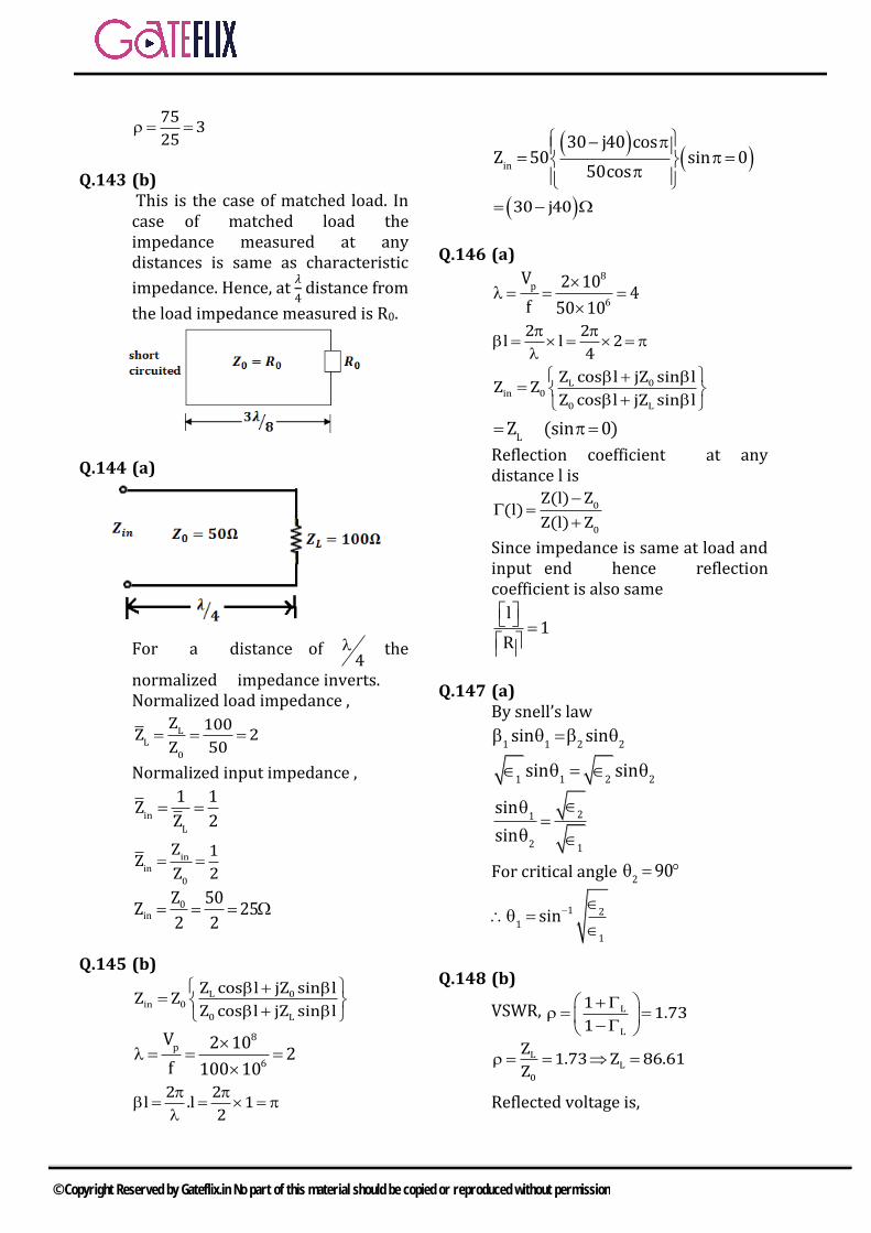
75 325
Q.143 (b) This is the case of matched load. In case of matched load the impedance measured at any distances is same as characteristic
impedance. Hence, at 𝜆
4 distance from
the load impedance measured is R0.
Q.144 (a)
For a distance of 4
the
normalized impedance inverts. Normalized load impedance ,
LL
0
Z 100Z 2Z 50
Normalized input impedance ,
inL
1 1ZZ 2
inin
0
Z 1ZZ 2
0in
Z 50Z 252 2
Q.145 (b)
L 0in 0
0 L
Z cos l jZ sin lZ ZZ cos l jZ sin l
8p
6
V 2 10 2f 100 10
2 2l .l 12
in
30 j40 cosZ 50 sin 0
50cos
30 j40
Q.146 (a)
8p
6
V 2 10 4f 50 10
2 2l l 24
L 0in 0
0 L
Z cos l jZ sin lZ ZZ cos l jZ sin l
LZ (sin 0)
Reflection coefficient at any distance l is
0
0
Z(l) Z(l)
Z(l) ZSince impedance is same at load and input end hence reflection coefficient is also same
l1
R
Q.147 (a) By snell’s law
1 1 2 2sin sin
1 1 2 2sin sin
21
2 1
sinsin
For critical angle 2 90
1 21
1
sin
Q.148 (b)
VSWR,
L
L
1 1.731
LL
0
Z 1.73 Z 86.61Z
Reflected voltage is,
© Copyright Reserved by Gateflix.in No part of this material should be copied or reproduced without permission
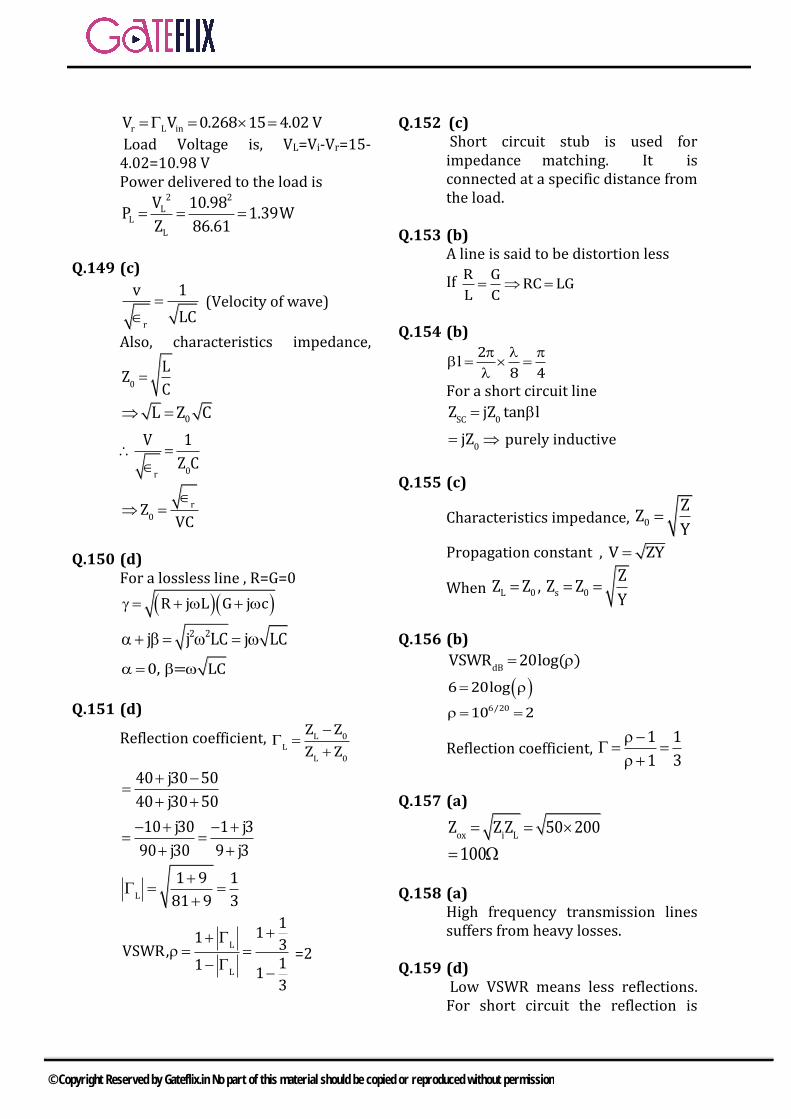
r L inV V 0.268 15 4.02 V Load Voltage is, VL=Vi-Vr=15-
4.02=10.98 V Power delivered to the load is
2 2
LL
L
V 10.98P 1.39WZ 86.61
Q.149 (c)
r
v 1LC
(Velocity of wave)
Also, characteristics impedance,
0LZC
0L Z C
0r
V 1Z C
r0Z
VC
Q.150 (d) For a lossless line , R=G=0
R j L G j c
2 2j j LC j LC
0, = LC
Q.151 (d)
Reflection coefficient,
L 0L
L 0
Z ZZ Z
40 j30 5040 j30 50
10 j30 1 j390 j30 9 j3
L1 9 1
81 9 3
L
L
111 3VSWR,11 13
=2
Q.152 (c) Short circuit stub is used for impedance matching. It is connected at a specific distance from the load.
Q.153 (b) A line is said to be distortion less
If R G RC LGL C
Q.154 (b)
2l8 4
For a short circuit line
SC 0Z jZ tan l
0jZ purely inductive
Q.155 (c)
Characteristics impedance, 0ZZY
Propagation constant , V ZY
When L 0 s 0ZZ Z , Z ZY
Q.156 (b) dBVSWR 20log( )
6 20log
6/2010 2
Reflection coefficient,
1 11 3
Q.157 (a)
ox i LZ Z Z 50 200 100
Q.158 (a) High frequency transmission lines suffers from heavy losses.
Q.159 (d) Low VSWR means less reflections. For short circuit the reflection is
© Copyright Reserved by Gateflix.in No part of this material should be copied or reproduced without permission

highest, then for horn and finally the reflections are minimum for matched load.
Q.160 (c)
For
4distance the normalized
impedance inverts whereas for
2distance the impedance value repeats.
Q.161 (b) For maximum power transfer
inZ 50
8
6
c 3 10 10mf 30 10
L 0in 0
0 L
z jz tan lZ Z
z jz tan l
100 j50tan l50 5050 j100tan l
50 j100tan l 100 j50tan l
j50tan l 50
jtan l 50
l
4
2 10l l4 8 8
1.25m
Q.162 (a) For short circuit the minima occur
at the load end. Now, when LR is
connected minima locations are
same. This means that L 0R Z
00 L
L L
Z 75VSWR, Z RR R
L
75 75R 253
Q.163 (a) sc 0Z jz tan l
Q.164 (b) cf
Since, frequency is doubled is halved
2l l
Since, is halved l will be doubled.
Hence the impedance would be jz
Q.165 (a) For a distortion less line
0LZC
2 100L Z C 50 50 10
0.25 H
Q.166 (b)
For distortion less line
RG
C CR.R RL L
Q.167 (d)
VEd
2VP V PRR
PE
d
Q.168 (b) 2 2
c1 m n
a b
© Copyright Reserved by Gateflix.in No part of this material should be copied or reproduced without permission
2 2
c1 m nf
a b2
Q.169 (d) For both TE and TM waves the propagation constants is same.
Q.170 (b) For 10H mode cut off frequency
2 2
c1 m nf
a b2
1 1 c2 a 2a
cc
c 2a 16cmf
Q.171 (a) EH
Q.172(a) 10TE mode is called the dominant
mode. It has lowest cut off frequency and highest cut off wavelength.
Q.173 (d)
11TE is the dominant mode in a
circular wave guide
Q.174 (c) For 10TE (dominant mode)
ccf
2a
8
9c
c 3 10a2f 2 10 10
1.5 m100
1.5cm (broad wall dimension)
Aspect ratio a 2b
ab 0.75cm2
Q.175) (d) The dominant mode of micro strip
line is Quasi TEM.
Q.176) (b) For TM mode the electric field
component is non zero in the direction of wave propagation
Q.177) (a) 0
g 2
c
f
1f
for wave
propagation cf f TM 0 TE 0
TEM mode is impossible inside arectangular wave guide V j for wave propagation which
is purely imaginary 0
Q.178) (d)
9
6
Resonantfreq 9 10QBandwidth 2.4 10
90002.4
Q.179) (d) only displacement current is the
axial current in a hollow wave guide
Q.180) (a)
p 2
c
cV cf
1f
2c
gfV c 1 cf 2
p gV .V cQ.181) (c)
© Copyright Reserved by Gateflix.in No part of this material should be copied or reproduced without permission

8
c3 10f 6.55GHz2 2.29
Maximum power handling capacity of the wave guide for the TE mode is
2
c
2max
f1
fP E a b
2
2
2 2 2
6.55111
5 10 2.29 10 1.02 102 120
31.11kW
Q.182 (d) For cylindrical waveguide 10TE and
11TM have highest attenuation .
They are called as degenerate mode.
Q.183 (b)
Directivity, 2
4DF ( )d
cos cos2F( )sin
for dipole
antenna D=1.64
Q.184 (d) Transmitted powers, T avgP P area
Tavg 2
P 200kwParea 2 r
2avg r40 wP a
m
Q.185 (b) For a Hertz dipole
Power radiated, 2rad radP I R
22
radlR 80
For 1st dipole,
cl 1.5m 3mf
2 2
radl 1R 80 80
2
For 2nd dipole
l 15 130 2
Q.186 (a) 8
6
c 3 10 100mf 3 10
22
radlR 80
2
2 580 1.97 2100
Q.187 (c)
Q.188 (a)
2
22 2rad
lR 80 80 0.03
20.072
Q.189 (c)
Q.190 (b) The front view of an end fire array is as shown below.
Q.191(b) Antenna arrays are used to enhance the directivity in a given direction.
Q.192 (a) Gain of the antenna is
e2
4 AG
2
2
2DR
© Copyright Reserved by Gateflix.in No part of this material should be copied or reproduced without permission

Q.193 (a) For taking antenna far field
22DR
Q.194 (d)
t t rr 2
P G GP .A
4 r
1 10 0.8w
4
Q.195 (c)
2 22 2
radl 1R 80 80 12.337
8 lossR 1.5
rad rad
input rad loss
R RR R R
12.337 0.89159 89.159%12.337 1.5
Q.196 (c) Maximum usable frequency is given by
2
MUF cDf f 1
2h
28009 1
2 300
15MHz Q.197 (c) TEM mode can never be supported inside a wave guide
© Copyright Reserved by Gateflix.in No part of this material should be copied or reproduced without permission