Embed Size (px)
Citation preview
ELECTROCHEMICAL STUDIES OF REDOX SYSTEMS
FOR ENERGY STORAGE
Report No. II
by
Cherng-Dean Wu
Daniel Scherson
Ernest Yeager
Annual Report : December 1981 to November 1982
NASA Project
Contract : NAG 3-219
NASA-Lewis
Cleveland, Ohio 44106
Case Center for Electrochemical Sciences
and The Chemistry Department
Case Western Reserve University
Cleveland, Ohio 44106
1 December 1982
https://ntrs.nasa.gov/search.jsp?R=19830006396 2018-06-01T13:37:43+00:00Z

TABLE OF CONTENTS
Page
I. ABSTRACT OF REPORT 2
II. INTRODUCTION AND OBJECTIVES OF RESEARCH 3
III. SUMMARY OF REPORT 4
IV. DATA AND PRELIMINARY DISCUSSION 6
1. Cr(H00)+/Cr(H00)
+ Couple on Rotating£ D 2. D
Nickel-Mercury Disk Electrode 6
A. Nickel-Mercury Electrode 6
B. The NaCIO, Supporting Electrolyte 7
C. Effect of Halides 12
D. NH.X as Supporting Electrolyte 14
2. Chromic Chloride Reduction in Acid Media on Au,Pb/Au and Graphite Electrode • 17
A. Gold Electrode 17
B. Lead/GoId System 24
i) Deposition and Stripping of Lead onGold Electrode 24
ii) Potential Step Experiment 28
C. Ordinary Pyrolytic Graphite 40
3. Fe(H.O) +/Fe(H.O)f+ Couple, Rotating Gold Ring-Disk2. D t. D
Electrode Studies in Acid Media 42
A. Effect of Halides 46
B. Effect of UPD of Bismuth on Reduction Kinetics 56
4. Spectroscopic Studies 65
A. Time Effects on Solution Composition(Visible Spectra) 65
B. XPS Measurement on Pre-electrolysis: Gold Cathode 65

I. ABSTRACT OF REPORT
Both chromium (II)/ (III) and iron (II)/ (III) couples have been studied
on various electrode surfaces in acidic perchlorate solution by using
rotating ring-disk techniques. It was found that chloride which forms
inner sphere coordination complexes with the redox species enhances the
electrode kinetics dramatically. Those are consistent with the results of
Weaver for chromium (II) / (III) couple and those of Weber for iron (II) / (III)
couple.
The effects of lead underpotential deposition and surface alloy
formation on the kinetics of the chromium (II)/ (III) couple on gold have
been studied using both linear sweep voltammetry and potential step tech-
niques . The lead IFD was found to slow down the kinetics of the reduction
of the Cr (III) species on gold surface although increase the hydrogen
overvoltage. The effect on the chromium(II)/ (III) kinetics can be explained
in terms of principally a double layer effect. The IFD lead species with
its positive charge results in a decrease in the concentration of the
Cr (III) species at the electrode surface. Similar phenomena were also
observed with bismuth underpotential deposition on gold for the iron(II)/
(III) couple.

II. INTRODUCTION AND OBJECTIVES OF RESEARCH
NASA-Lewis has developed a promising redox electrochemical system
for energy storage. This system is based on an electrochemical cell with
two compartments separated by an ion selective membrane. The electrode
reaction at the negative electrode involves the chromium (II)/ (III) couple
while that at positive electrode involves the iron (II)/ (III) couple.
Solutions containing these species are. circulated through carbon felt
electrodes where the reduction of Cr (III) and oxidation of Fe (II) occur
during charging and the reverse reaction occur during discharge.
NASA-Lewis has greatly improved the performance of the carbon electrodes
used for the chromium (II)/ (III) reactions by incorporating gold in the carbon
felt matrix and by adding lead chloride to the solution. The resulting gold-
lead catalyst greatly reduces the overvoltage normally associated with this
redox couple while maintaining the hydrogen overvoltage sufficiently high
to depress the competing H_ generation reaction.
While the gold-lead catalyzed carbon felt electrodes afford high perfor-
mance, a full understanding of the electrochemical and other processes involved
at these electrodes has not yet been achieved. The proposed research is directed
to the study of the factors controlling the kinetics of oxidation-reduction
couples on various electrode surfaces.
During the past 12 months, NASA-Lewis has sponsored research at Case
Center for Electrochemical Sciences on the behavior of the chromium (II)/ (III)
couple on electrode surfaces including gold, lead and graphite. This investi-
gation is aimed at understanding the role of the electrode and electrolyte
components in controlling the electrode reaction kinetics. Such fundamental
understanding should provide the insight, necessary for the optimization of
the present system and for the identification of alternative and perhaps
more effective electrode-electrolyte systems for energy storage applications.

III. SUMMARY OF RESEARCH
The research during the first 12 months of this project is summarized.
The experimental studies have included the following measurements :
1. Linear sweep voltammetry studies
The underpotential electrodeposition of lead has been examinedon gold surface using linear sweep voltammetry. At more cathodicpotential, bulk deposition and alloy formation occur. The under-potential deposition of bismuth on gold surface also has beenstudied.
2. Rotating ring-disk electrode studies of the chromium (II)/ (III)couple
Rotating ring-disk electrode techniques have been used to examinethe effect of the underpotential deposition of lead on the kineticsof the chromium (II)/ (III) couple on gold. This technique permits theseparation of the current components for the redox couple and forthe underpotential deposition of lead. In some instances it shouldalso be possible to examine the reduction kinetics for the chromium(II)/(III) couple in the presence of a substantial 1L generationcurrent using a ring with high hydrogen overvoltage to monitor eitherthe consumption of Cr (III) or the production of Cr(II). The rotatingdisk electrode provides quantitative control of the transport of react-ant and products to and from the rotating disk electrode surface.
3. Potential step studies of the effects of UPD layers on the kinetics ofchromium (III) reduction
These experiments involve polarizing a rotating gold disk electrodeat a potential where UPD does not occur and then stepping the poten-tial to a value where UPD occurs.Ihder these conditions with a lowbulk concentration of the UPD species, the deposition of the UPD layeroccurs very slowly under pure diffusion control. The coverage of theUPD layer can then be calculated as a function of time from the diffu-sion flux. With chromium (III) also present, the dependence of the rateof the chromium (III) reduction on the UPD coverage can be determinedfrom the time dependence of the chromium (III) reduction current.
4. Raman studies of adsorbed chromium complexes on electrode surfaces
Surface enhancement of the Raman signals (SERS) by factors of up to10 are obtained with adsorbed species on metals such as silver andgold. Advantage is being taken of this enhancement to check on thepossible specific adsorption of various inner sphere chromium (III)complexes on these electrode surfaces. So far, preliminary measure-ments have been carried out with the mono- and di-thiocyanate chromium

complexes adsorbed on silver. Strong signals have been obtained,presumably from monolayers, but detailed analyses of the Ramandata have not yet been made. Further work is planned.
5. Ultraviolet-visible absorption spectroscopy
The [Cr(lLO)6]3+, [ Cr (H Cl]2* and [ Cr (I O)4C12]
+ species havebeen monitored using W-visible absorption spectroscopy. Furthermeasurements using UV-visible absorption are planned to establishthe concentration changes for these species as a consequence ofthe electrode processes as well as homogeneous processes.
The voltammetry and polarization measurements have led to the followingconclusions :
1. The reversible potentials differ substantially for the [Cr(ILO),][ Cr (10) Cir and [ Cr ( I O C l couples. i b
3+
2. The UPD lead on the gold slows down the kinetics of the reductionof the various chromium (III) species on the gold surface. This effect isprobably principally associated with a double layer effect. The UPDlead species with its positive charge results in a decrease in theconcentration of the chromium (III) species at the electrode surface(in the outer telmholtz plane).
3. The principal beneficial role of the lead on the reduction of chromium(III) species on gold is to increase the hydrogen overvoltage and thussuppress the competing IL generation reaction.
4. Anion bridging does not play an important role in the reduction of[Cr(H_0) Cl] on gold, probably because the negative charge on thecathode causes this complex to approach the electrode surface in theouter Helmholtz plane with the chloride ligand directed away from theelectrode surface.
5. Anion"~bridging does appear to be important in the oxidation of chromium(II) to chromium (III). The model proposed to explain the kinetics isthat the chloride ion is specifically adsorbed on the electrode surfaceand then transfered into the inner coordination sphere of the chromium(III) ion to yield [ Cr_(lLO)5Cl] . UPD can increase the surface concen-tration of adsorbed Cl and thus promote the formation of the chloridecomplex. In addition to the IPD of lead, the UPD of bismuth has alsobeen examined on gold. Some kinetic measurements have also been carriedout for the iron (II) / (III) couple on the UPD Bi/Au surfaces.

IV. DATA AND PRELIMINARY DISCUSSION
1. Cr(H00)^+/Cr(H00)i:+ Couple on Nickel-Mercury Disk Electrode/ D / D
A. Nickel-Mercury Electrode
The chromium(II)/(III) couple in an acidic aquo solution is a simple
one-electron transfer reaction having very irreversible kinetics in the
absence of bridging ligands. It is necessary to have a high hydrogen
overvoltage electrode to study the reduction kinetics of this couple.
Mercury affords such a high hydrogen overvoltage and has been used for
previous studies of this couple at Case Center for Electrochemical
Sciences. To check out this couple under steady state and well defined
transport conditions, a rotating mercury coated nickel disk electrode
has been used in the early phases of the present study. For practical
purposes the electrochemical surface properities are close to those
of a mercury electrode. The solubilities of nickel in mercury and vice
verse are very low. The surface layer is almost pure mercury.
The mercury coated electrode is easily made and is easy to use. The
following procedure will give a nickel-mercury electrode with high
hydrogen overvoltage. A polished nickel disk is subjected to a few
minutes of ultrasonic cleaning immediately before the mercury-deposi-
tion procedure to remove any organic film and trapped particles on the
electrode. The electrode is then introduced into a solution of ca. 0.5
mM % (NO ) and 0.1 M K10,. A potential of -1.10 V vs SCE is then
applied to the nickel disk electrode and maintained until hydrogen
evolution is apparent from bubble formation. A nickel grid is used as
(1). S. Donovan and E. Yeager, " The Electrode Kinetics of the Chroraous-
Chromic Couple " OXR. Technical Report No. 24, Case Western Reserve
University, Cleveland, Ohio, Oct. 1969.

counter electrode. Deposition is repeated for several times.
The mercury coated surface of the electrode has a reasonable high
hydrogen overvoltage, although not as high as very pure mercury. Actu-
ally the hydrogen overvoltage on a stationary film of mercury was
intermediate between that on smooth solid electrode and on dropping
mercury.
B. The NaCIO, Supporting Electrolyte
The specific adsorption of the ions of the supporting electrolyte
has long been known to influence profoundly the rate of electron-trans-
fer reactions at metal-solution interfaces. A difficulty faced with
-2+ 3+redox couples of the type M /M with high charged ions is that the
double-layer effects in the kinetics are quite significant even in con-
centrated electrolytes. The double-layer corrections are smallest and
can be applied with greatest confidence using supporting electrolytes,
at high ionic strengths in the absence of specific ionic adsorption
with the concentration of the redox species small in comparison with
that of the supporting electrolyte. Perchlorate was chosen because
this anion combines weak specific adsorption with only a very small
tendency toward complex formation in the bulk of the solution. Per-
chlorate ions are adsorbed to a very low degree on conventional elec-
trodes such as Ft, Au and %. Their adsorbability is far lower than
for sulfate ions and, except at higher positive potential, their
adsorption can be neglected. Inner coordination complexes between
chromium ions and the CIO, form only to a very small extent except in

very high concentration of perchlorate. The concentration of chromium
(III) employed was always kept sufficiently below those of the supporting
electrolytes so that these ions made a negligible contribution to the
diffuse-layer structure.
Among the solid electrodes, it seems that a mercury coated electrode
is the only one which can be seen both cathodic and anodic waves of
chromium (II)/ (III) couple in perchlorate electrolyte. In perchlorate
supporting electrolyte, the chromium(II)/(III) couple gives well defined
3+cathodic and anodic waves, as is shown later. The reduction of Cr
proceeds at negative potential where the perchlorate is not signifi-
cantly specifically adsorbed. The reduction and oxidation waves are
well separated and have different shapes that reflect, in part, the
different influence of the diffuse double layer on the reduction and
oxidation reactions, respectively.
Rotating nickel-mercury disk electrode data are shown in fig.2.
(2). K. M. Jones and J. Bjerrum, Acta. Chem. Scand. 19 (1965) 974.


10
oLT>
oo
ooCNJ
current
omCM
oo
oi
oi
O1
00
oI
o•
1—II
wu
w a61 oO
J-lOo
rH CM
o
in s-iT-l 4J•O O
0)rH iH(1) W
C O T3i-l Q)
T3 CJ 4J(U ffl n)w a oCO -HO S T)o e c
U O(-1 <-< ••0) U 0)e* to1C S n0 o cc • oO O -H•H 4J4J C tOU -r\ W3 O
T) rn«SU x-sV4 «* •
U — i a)vO JJ
M • tOO O H
c a)O <U
wQJ>M 4-> CO3 3O rH •
OTMC w go o•rl .AJ (1) CNtO T3 •N O O
CO O COH Q) Q)0 «H l-i
PL, (U CO
tN
0)^J
W•rl '

11
1.5
01
o
H 1.0
0.5
0
-1 -1/2Figure 3: I vs. (jj plots of data in Fig. 2 for reduction of
Cr (ILO) on nickel-mercury electrode.

12
C. Effect of Halides
In perchlorate supporting electrolyte with a pH of 2 or less (to avoid
hydrolysis), the hexaaquochromium (II)/ (III) couple exhibits an irreversible
wave. With halides in solution, the anodic wave of couple is shifted toward
more negative potential. When the supporting electrolyte contains bromide
ions, the couple produces two reduction waves: one corresponding to the
uncomplexed chromium (III) reduction, the other to the bromide complex
chromium (III) reduction. Only a single anodic wave is apparent corres-
ponding to the formation of the complexed chromium (III) from chromium
(II). The bromide is adsorbed on the electrode surface and transfered
into the inner coordination sphere of the Cr. The kinetics are very slow
for the reduction without the bridging bromide ligand. A representative
voltammetry curve with bromide is given in"Fig. 4.

13
E vs, SCE (V)
3+Figure 4: Voltammetry curves for 2mM Cr(tLO)6 on stationary nickel-mercury disk
electrp.de. Electrolyte: 0.01M NaCIO, and 0.01M HC10,. Electrode area:0.2 cm . Sweep rate: 50 mV/s. Temperature: 22°C. A. without NaBr added.B. with 1.67 mM NaBr added. Quasi-steady-state measurement (curves recordedafter many cycles).

14
D. NH,X as Supporting Electrolyte
In 0.1 M ammonium chloride or ammonium bromide, chromium(II)/(III) couple
gives well defined anodic and cathodic waves. The voltammetry curve of chromium
(II)/(III) couple shows a much more reversible behavior in NH.X supporting
electrolyte than that in pure perchlorate solution. While the cathodic wave
potentials are not changed very much and remain almost the same, the anodic
potentials vary with the supporting electrolyte used.
In presence of ammonium halide the anodic wave potential is found to be
more negative than that with NaX in acidic solution. It appears that both
ammonium and halide ions have an influence on the behavior of the chromium
(II)/(III) couple. It is likely that ammonium ions (NH.) adsorb on mercury
surface to modify the kinetics of electrode reaction.
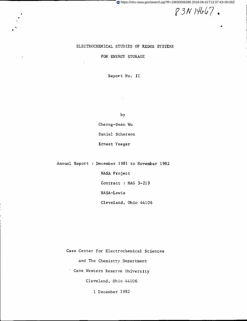
When NH.Br was used as supporting electrolyte, the cyclic voltammetry
curve was changed from what it was in a NH.C1 supporting electrolyte. (Fig.6).
The original cathodic peak was slightly changed from what it was in the pure
perchlorate or NH.C1 media, the anodic peak was shifted toward negative poten-
tials, and a new cathodic peak at potentials positive to the original cathodic
peak appeared. The new cathodic peak which was not seen in NH.C1 electrolyte
2+corresponds to the reduction of [Cr(H?0) Br] . It is believed some'bromide
2+ions have already coordinated to the Cr to form [Cr(H 0) Br] during the
back scan, but not chloride ions.
15
E (SCE)/V,
20
10
n
20
o
Figure 5: Voltammetry curve for 2 mM Cr (1LO), on nickel-mercury disk electrode.Quasi steady-state measurement. Xcurve recorded after many cycles).Electrolyte: 0.01M HC10,, 0.1M NH.C1 (pH: 2.4). Electrode area: 0.2 cm''Sweep rate: 100 mV/s.

-1,1 -0.9 -0,7E(SCE) /V,
16
-0.5—i—
-0.3
A
o _
n>
cathode
25
15
5
0
5
15
25
35
45
55
Figure 6: Voltammetry curves for 2 mM Cr(ILO).. on nickel-mercurydisk electrode with NH.X as supporting electrolyte. _Quasi steady-state measurements. Electrode area: 0.2 cm .A. in 0.01 M ffilO , 0.1 M NH.C1 <ptt 2 .4)B. in 0.01 M HClo£, 0.1 M NRVBr (pH: 2.3)

17
2. Chromic Chloride Reduction in Acid Media on Au, Pb/Au and GraphiteElectrodes
A. Gbld Electrode
3+ 2+As indicated in section 1, the Cr (ILO) /Cr (ILO) couple has
sluggish electrode kinetics on nickel-mercury electrode in acid media
at pHof 2. Such low pH solution was used to prevent the hydrolysis of
3+chromium couple. Under these conditions, the reduction wave of Cr(ILO),
occurs at potentials close to that for hydrogen evolution. It is difficult
3+to study the reduction of Cr(ILO), without interference of hydrogen
evolution.
The high overvoltage for Cr (III) reduction is due to the high free
energy of activation just as in the homogeneous case. In contrast to
the nickel-mercury electrode, the reduction of Cr(ILO), does not occur
on crystalline gold disk electrode without hydrogen evolution. Unlike
Cr(C10.)_, the reduction in solutions prepared from CrCl_ occurs on gold
disk electrode before hydrogen evolution with a well defined reduction
wave. Voltammetry and polarization curves are shown in Fig. 7-10. In
3+ 2+view of the results for the Cr (ILO) /Cr (ILO) couple even with the
introduction chloride into solution, the inner coordination sphere
corapiexes--of chromium with chloride play the major role in the reduction
on gold electrode in chromic chloride solution. From a coordination-com-
plex standpoint the binding chloride perturbs the transition-state of
the electron-transfer process as well as the initial-state of the
chromic complex. From a electrochemical standpoint the bound chloride
may adsorb on the electrode surface and participate as a bridging ligand,

18
thus facilitating the electron transfer.
It was found that the results are not reproducible; currents increase
with extended cycles. Probable reason for this is the changing of solu-
tion composition with time. The commercially available chromic chloride
is assigned the molecular formula [ Cr (ILO) ,C1 ]C1* 2ILO. On dissolving
this complex in water, however, the metal-bound chlorides are successively
replaced by water molecules, giving first blue-green [ Cr (ILO) C1]C1»1LO
and finally violet [ Cr (1 0) ]C1 .
With bridging chloride adsorbs on electrode surface to facilitate
2+ +electron transfer, both Cr (1LO) Cl and Cr (ILO) Cl are electrode
active species. Unfortunately their electrode kinetics are not the same
2+making the analysis work difficult. CrClLCO.-Cl with its dipositive
charge will have a higher concentration in the outer Ifelmholtz plane
than Cr(lLO),Cl7 at potentials negative to the potential of zero charge.
Beside that, the steric interactions between ligands are unfavorable to
+ 2+Cr(lLO),Cl within the double layer. The closest distance of Cr (H,0) Cl
to electrode surface is therefore shorter than that of Cr(H_0).Cl2.
2+Among these components in chromic chloride solution, the Cr (H-,0) Cl
has the fastest kinetics on gold electrode. As time passing after freshly
prepared, the Cr (ILO) Cl loses its bridging chloride producing more
2+Cr(H_0) Cl species in solution and therefore the current increases
with extended cycles. (Fig. 8).

19
Figure 7: Voltammetry curves for 3mM CrCl_ on gold disk electrode.Electriolyte: 0.1M NaCIO, and 0.01M HC10,. Electrode area:0.2 cm. Sweep rate: A. lOmV/s B. 50mV/s C. lOOmV/s.

20
cycl
900 rpm
50 oc
re40 3
30
20
10
-0.7 -0.6 -0.5 -0.4 -0.3 -0.2 -0.1£(SCE)/ V
0.1 0.2
-0.6 -0.5 -0.4 -0.3 -0.2 -0.1
cycle900 rpm
0 0.1 0.2
20
40
60
80 1
n>
100
120
Figure 8: Polarization curves for reduction of freshly prepared CrCl- ongold ring-disk electrode. Ring potential: 0.6V. Rotation rate:900 rpm. Sweep rate: lOmV/s. Solution: 3mM CrCl in 0.1M KaCIO,and 0.1M HC10..
4

21
Large hyteresis of CrCl_ reduction on gold surface under convection
was observed. (Fig. 8-10). The I-E curves do not level off at cathodic
potentials, -0.57V vs. SCE, where the reduction processes are under pure
diffusion control. Before the potential of hydrogen evolution, the currents
decrease quickly even during the back scan of potential. A re-enhanced
current occurs during back scan at the same potential where current chan-
ges dramatically during forward scan. The turnover of current occurs at
-0.57V vs. SCE., which is independent of the rotation rate. (Fig. 10).
This phenomenon is probably associated with the inner-sphere mechanism
in which the bridging chloride adsorbs on the gold surface. At potentials
negative to -0.57V vs. SCE. the bridging chloride de-adsorbs from the
electrode surface. Therefore the orientation of the oxidized species on
gold surface changes with the water ligand directing toward the electrode.
Because of the slowness of the electron transfer with the water ligand com-
pared with the chloride ligand, the electrode kinetics slow down at these
potentials. The re-enhancement of currents during back scan is due to the
re-adsorption of bridging chloride, as is .shown below:
CATHDDE CATHDDE
Chloro- o Aquo-

22
900 rpm
E(SCE) (V)
Ring (0.6v)
0.2
E(SCE) (V)-n.fi
900 rpm
bridged Clre-adsorpti
evolution
=JDL4L JLZ
30
60
150
Disc
bridged Cl desorption
Figure 9: Polarization curve for reduction of CrCl, on goldring-disk electrode. Ring potential: 0.6V. Rotationrate: 900 rpm. Sweep rate: lOmV/s. Solution:3mM CrClin 0.1M NaClO. and 0.01M HC10..A 4

23
Ring (0.6V)
2500
1600
900
rpm
E(SCE)/ V.
-0.2
80
60
40
20
0
oc-sn>
0.2
Figure 10: Polarization curves for chromic chloride reduction on rotating
gold ring-disk electrode in acid media. Solution: 3mM CrCl,O
in 0.1 M N a C l O . , 0.01 M HC10.. Sweep rate: 10 mv/s. Electrode2
area: 0.20 on , Rotation rates as specified.

24
B. Lead/Gold System
i). Deposition and Stripping of Lead on Gold Electrode
The role of lead on gold surface is important in the understanding
of the kinetics of chromium(II)/(III) couple. Underpotential deposition
as well as the bulk deposition and stripping of lead on crystalline gold
electrode have been studied in perchloric acid.
The effect of lead on the kinetics of the chromic reduction can be
studied by rotating ring-disk electrode technique. Cr(II) which is reduced
at the disk can be reoxidized to Cr(III) at the ring. The ring potential is
fixed at such a positive value (0.6V vs. SCE) that the reoxidation of Cr(II)
occurs under pure diffusion control. Because no lead deposition occurs at
the ring, the ring currents are totally due to the oxidation of Cr(II) to
Cr(III).
It was found that the underpotential deposition of lead on gold
disk results in a net decrease of the reaction kinetics as compared
with that on the bare metal. This effect is probably principally asso-
ciated with a double layer effect. The UPD lead species with its posi-
tive charge results in a decrease in the concentration of the Cr (III)
species at the electrode surface (in the outer Helmholtz plane).

-25
E(SCE) (V)
E(SCE) (V)
FIGURE 11: UNDERPOTENTIAL DEPOSITION OF LEAD ON GOLD
SOLUTION: 0,3 MM PstNO-^)R9
10 iW/s, ELECTRODE AREA: -- n ° ""*-STAGNANT SOLUTION,
ELECTRODE, SOLUTION: U,3 MH PBtNO-^ IN
0,01 M HCLO^, 0,1 M NACLO/,, SCAN RATE:0,2 CM

26
IESL9001600250036004900
-100
FIGURE 12": SAME AS FIG, n WITH ELECTRODE UNDER ROTATION, ROTATIONRATES AS SPECIFIED,

27
900 rpm
Ring
-0.5 -0.4 -0.3V-0.2 -0.1
12
10 £-S
ft)
E(SCE)/ V.
900 rpm
Figure 13: Polarization curves for chromic chloride reduction on rotatinggold_ring-disk electrode. Solution: 3 mM CrCl in o.l M 1C10,6-10 M PbO. Sweep rate: 10 mV/s. Electrode area: 0.2 cm.Ring potential: 0.6V vs. SCE.
28
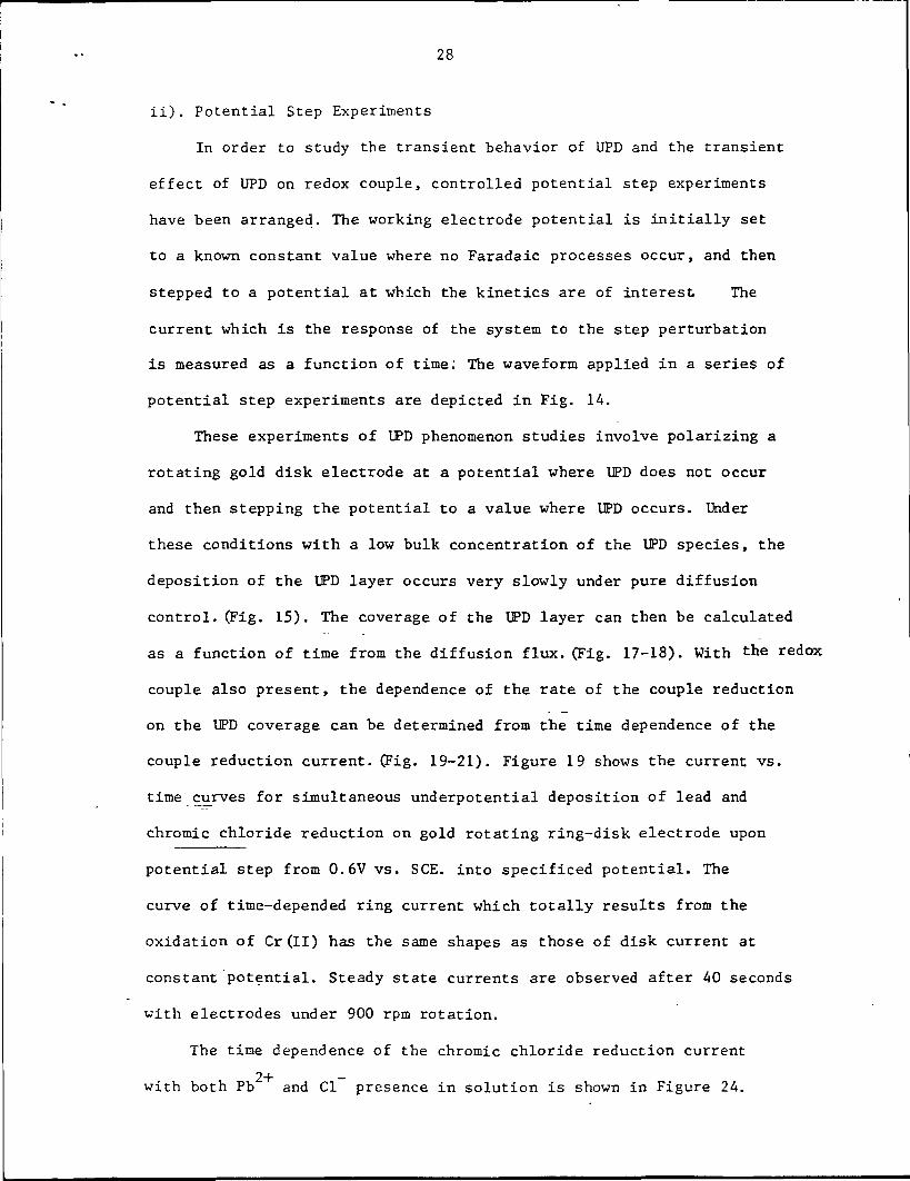
ii). Potential Step Experiments
In order to study the transient behavior of UPD and the transient
effect of UPD on redox couple, controlled potential step experiments
have been arranged. The working electrode potential is initially set
to a known constant value where no Faradaic processes occur, and then
stepped to a potential at which the kinetics are of interest The
current which is the response of the system to the step perturbation
is measured as a function of time: The waveform applied in a series of
potential step experiments are depicted in Fig. 14.
These experiments of UPD phenomenon studies involve polarizing a
rotating gold disk electrode at a potential where UPD does not occur
and then stepping the potential to a value where UPD occurs. Under
these conditions with a low bulk concentration of the UPD species, the
deposition of the UPD layer occurs very slowly under pure diffusion
control. (Fig. 15). The coverage of the UPD layer can then be calculated
as a function of time from the diffusion flux. (Fig. 17-18). With the redox
couple also present, the dependence of the rate of the couple reduction
on the UPD coverage can be determined from the time dependence of the
couple reduction current. (Fig. 19-21). Figure 19 shows the current vs.
time curves for simultaneous underpotential deposition of lead and
chromic chloride reduction on gold rotating ring-disk electrode upon
potential step from 0.6V vs. SCE. into specificed potential. The
curve of time-depended ring current which totally results from the
oxidation of Cr(II) has the same shapes as those of disk current at
constant potential. Steady state currents are observed after 40 seconds
with electrodes under 900 rpm rotation.
The time dependence of the chromic chloride reduction current
2+ -with both Pb and Cl presence in solution is shown in Figure 24.

29
time
Figure 14: Step waveforms applied in a series of experiments.

30
0 w ?n ant/ sec.
fie d e f
1
2
< 3 .fc
4OJs_S-3u
0
Co>s_S-3o
10 30
( f t )
Figure 15: Disk current vs. Time curves for gold rotating ring-diskelectrode in 0.1 M HC10, in absence of Cr (III) and Pb(ll).Potential step from 0.6V into indicated potential. Rotationrate: 900 rpm. A. No NaCl B. with addition of 3mM NaCl.a, b, c, d, e, f, g, h, i are same as in figure 16.

31
a). 0.0V
b). -0.05V
c). -0.10V
d). -0.15V
e). -0.20V
f). -0.25V
g). -0.30V
h). -0.35V
i). -0.40V
Figure 16:"Current vs. Time curves for rotating gold ring-disk electrode
in a solution containing 0.1 M NaC104> 0.01 M HC104 and 6'10~ f MPbO upon potential step from 0.6V into indicated potential.Rotation rate: 900 rpm, ID= 0.K

32
E = -0.40V
Figure 17: Charge vs. Time curve for underpotential depositionof Lead on gold at fixed applied potential.Data taken from Fig. 16.

33
'20
Ring (0.6V.)
CJ
o
10
5
-0.40V
-0.35v
-0.30v-0.25v
15 25 35 45 55 65 75 85 t(Sec)
10
2O
30
40oi-
50
t(Sec)
5 .15 25 35 • 45 55 65 75 85
-0.25v
-0.30v
-0.35v
-0.40v
Disc
Figure 18: Current vs. Time curves for simultaneous underpotential depositionof lead and chromic chloride reduction on gold rotating ring-diskelectrode upon potential step from 0.6V into indicated potential.Solution: 3 mM CrCU, 6. 10- M PbO in 0.1 M NaCIO, and 0.01 M HC10
3'Rotation rate: 900 rpm. Ring potential: 0.6V vs.0.2 on.
i *
>CE. Electrode area:

34
A for Cr(III) reduction
Q/^coul.
lead depositionin charge units
Figure 19: Three dimensional representation of current vs. potentialand charge of UPD. Data from figure 16, 18.

35
I//I A
co•H4-1U3
E(SCE)/V.
20 QAUCOU,?0
lead UPD coverage in charge units
Figure 20: Same as figure 19, at Q = 74.3>Ucoul., E = -0.40V

36
3, 15
10
Rina (0.6v)
-f-
-0.42v-0.40v
-0.35v
-0.30v-0.25V
0 10 20 30 40 50 60 70 80 90t(Sec)
0 L 1.0 2P 30 40 50 60 70 80 9JD
5
10
15
20
25
30
35
40
t(Sec)
40v
-0.40v Disc
Figure 21: Current vs. Time curves for the simultaneous underpotentialdeposition of lead and chromic chloride reduction on a-rotating ring-disk Au electrode upon potential step from0.6V into indicated potential. Solution: 3mM CrCl_ in0.1 M HC10 andf 6-10 M PbO + 3mM NaCl,--6.10 M PbO, ••'• 3mM NaCl.Rotation rate: 900 rpm.

37
The rotation dependences of the transient behavior for simultaneous
underpotential deposition of lead and chromic chloride reduction on the
gold disk electrode at constant potential are shown in figure 22-23. The
time required to reach steady state decreases with rotation rate.

38
o>3
10 20 3D 40 60t/ sec.
rpm
E = -0.25V
10oc.-5
n>3
20
_2P_ 30t/ sec.60
900
1600250036004900
E = -0.30 V.
Figure 22: Disk current vs. Time curves for simultaneous underpotential depositionof lead and chromic chloride reduction on gold electrode with rotationrates change as indicated. Potential gtep from 0.6V into indicatedpotential. Solution: 3mM CrCl , 6'10~HC10,.
M PbO in 0.1 M NaC104 and 0.01M

39
30 40 50t/ sec.
60
900
1600
2500
3600
4900
20 30 40 50 60t/ sec.
E = -0.40V.
rpm
900
16002500
Figure 23: Same as figure 22.
40
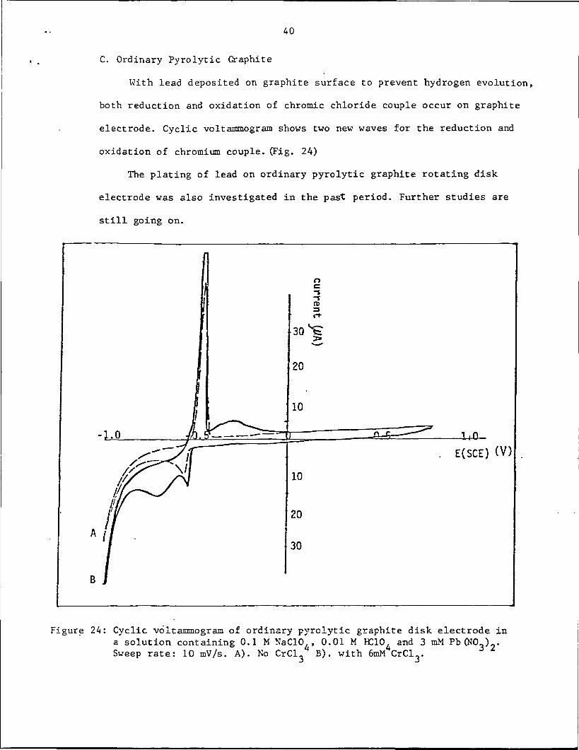
C. Ordinary Pyrolytic Graphite
With lead deposited on graphite surface to prevent hydrogen evolution,
both reduction and oxidation of chromic chloride couple occur on graphite
electrode. Cyclic voltammogram shows two new waves for the reduction and
oxidation of chromium couple. (Fig. 24)
The plating of lead on ordinary pyrolytic graphite rotating disk
electrode was also investigated in the past period. Further studies are
still going on.
E(SCE) (V)
Figure 24: Cyclic voltammogram of ordinary pyrclytic graphite disk electrode ina solution containing 0.1 M NaCIO , 0.01 M IC10, and 3 mM Pb (NO ) .Sweep rate: 10 mV/s. A). No CrCl B). with 6mM CrCl .

41
E(SCE) (V)
rpm
900
1600
2500
3600
4900
2000
1000
25
50
75
100
125
150
175
200
r>-s-jn>
Figure 25: Polarization curve for lead deposition and stripping on ordinary ^pyrolytic graphite rotating disk electrode. Electrode area: 0.2cm .Solution: 0.1 M NaCIO,, 0.01 M HC10 and 3 mM PbO. Sweep rate: lOmV/s.Note: change in ordinate for anodic vs. cathodic curves.

3. Fe(H00)^+/Fe(H-0)f*~ Couple, Gold Ring-Disk Studies in Acid Media2 o 2 o
3+ 2+The kinetics of the Fe(H00),, /Fe(H00), couple were studied on a/ D / O
gold rotating disk electrode in 0.5 M HC10, solution. Without anions
other than the CIO, of the supporting electrolyte, moderate electrode
kinetics have been observed. It was found that the process is very
sensitive to the surface condition; trace concentrations of impurities
made the results unreproducible. The cyclic voltammogram and polariza-
3+ 2+tion curve of Fe(H.O), /Fe(H»0), couple are shown in Figures 26 - 27.
2. O f- O
The resulting Levich plots in which the curves are parallel confirm
that the electron transfer reaction is first order in kinetics. For
first order reaction: ,. .-1 ... v-1 , . JL/2N-1CO = diJ + (B tw )
i,: current for pure kinetic control
1/2BCO ?= i, : diffusion limiting current

43
anode
E (SCE)/ V.
300"
Figure -26 : VoItammetry curves for 6mM Fe(H»0) on gold disk electrode
in 0.5 M H310,. Electrode area: 0.458 cm . Sweep rate:
A: IChnV/s, B: 50mV/s, C: lOOmV/s.

oa
0)•ot-i4Jo0)
CL0)0)
13r-lO00
00
•H4JCO4JOJ-4coco•H4JCJ3
"D0)
CO0)
3O
O•H4-1CON
CO
OIX,
CNJ
oo
CM
O
GOm
ncu
cu13OM4J
U0)
rHw
OiH
a
3i-lO
T30)
•HC O
•H OJO.CO
COcfl
x-x CO<• 0)
O 4J»-l Cfl
co•H4JCO
CUe
CU4Jcfl

45
1 1.5
1.0
0.5
01.0 2.0 3.0
(0»-1/2 102 rpnf1/2
-1 -1/2:igure 28: I vs. GJ plot of data in Fig. 27

46
A. Effect of Hal ides
3+ 2+The electrode reaction of the Fe(H00),. /Fe(H00), couple is stronglyC O C . V
affected by halide anions adsorbed on the electrode surface. In the absence
of halides the shape of the voltammogram with separated cathodic and anodic
waves indicates a relatively slow electrode reaction. However, it was found
that the addition of even a small amount of halides leads to a change in
polarization curves to a shape corresponding to a much more rapid electrode
reaction. The marked increase in the rate of the electrode reaction of3+ 2+Fe(H20)g /Fe(H20)g couple has long been believed due to changing the
electron-transfer process from outer-sphere mechanism to inner-sphere
mechanism with halide as a bridge between electrode and iron complex.
Corresponding cyclic voltammogram and polarization curves of iron(II)/(III)
couple with halides presence in solution are shown in the following figures.

47
E(SCE)(V)
-300
Figure 29: Effect of chloride on the kinetics of iron(II)/(III) couple ongold electrode in acidic media. Solution: 6 mM FeCClO.)., in,,0.5 M HC10,. Electrode: gold disk (Pine) Area: 0.458 J cm.
B). 3 mM NaCl added.•> A • L. i CU Ul l/UC • QO I 0
Sweep rate: 50 mV/s. A). No chloride

48
anode
cathode
E(SCE)/ V.
Figure 30: Voltammetry curves for ferric-ferrous couple on gold disk electrode
in acid media containing chloride. Solution: 6mM Fe (CIO,) in
20.5 M HC10, and 3mM NaCl. Electrode area: 0.458 on (Pine). Sweep
rate: A: lOmV/s, B: 50mV/s, C: lOOmV/s.
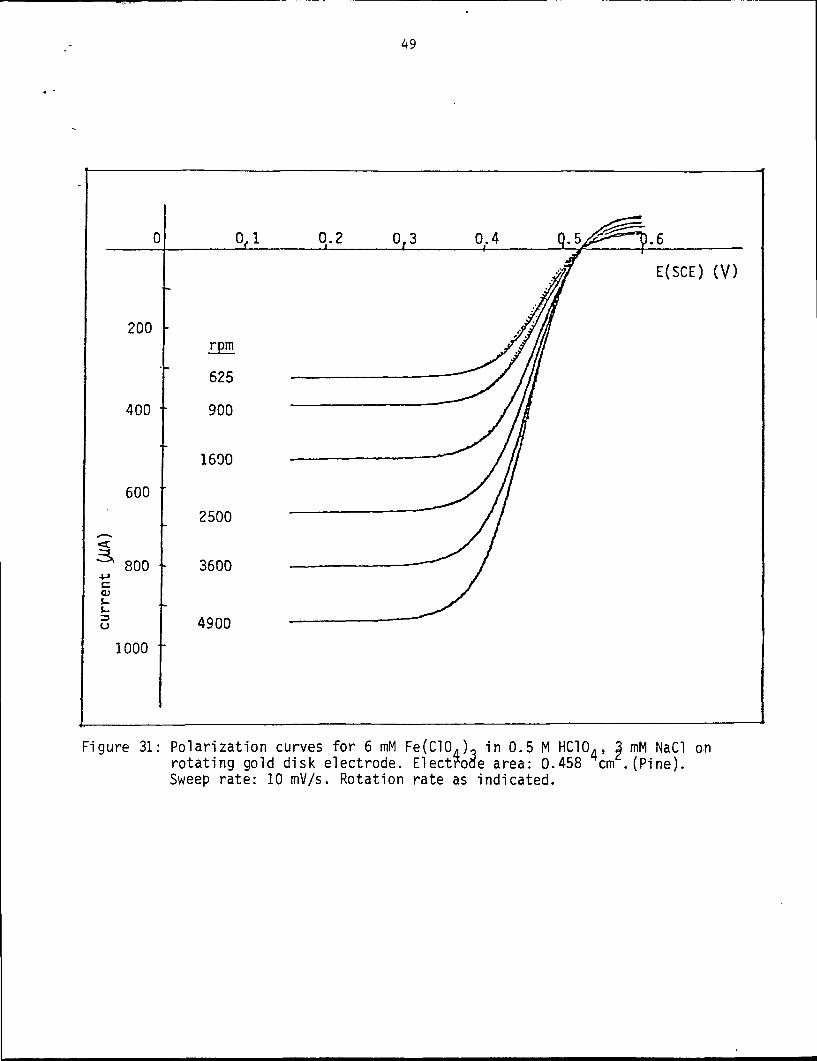
49
Figure 31: Polarization curves for 6 mM Fe(C10j, in 0.5 M HC10., 3 mM NaCl onrotating gold disk electrode. Electrode area: 0.458 cm .(Pine).Sweep rate: 10 mV/s. Rotation rate as indicated.

50
-1/2 ..2 -1/2.O «10 (rpm )
Figure 32: I"1 vs. 6o"1/2 plot of data in figure 31.

51
LUQOtrHCJLLJ_lLU
CO -3""- OQ -I
OQ ^ Q_l LU LUO U_ QID Q
2: hO LU— Qf- .. _< z cel- o oo -- -io: i- DC
o o ooo 2:
zO CO -—• ^^ QH > LUO S HZ5 <Q O OLU i—I —•ce Q
-- z+ LU —•
x-s < COO Qi <£
CM
LU O LULL. 00 I-
<o: - o:OCX]u- s: z
o o111 f—I
> -, I-cx C* <
Oi—i •» ^3I- < O< LU _lM Cf. C_3
—I COo --
COCO
LU
CD
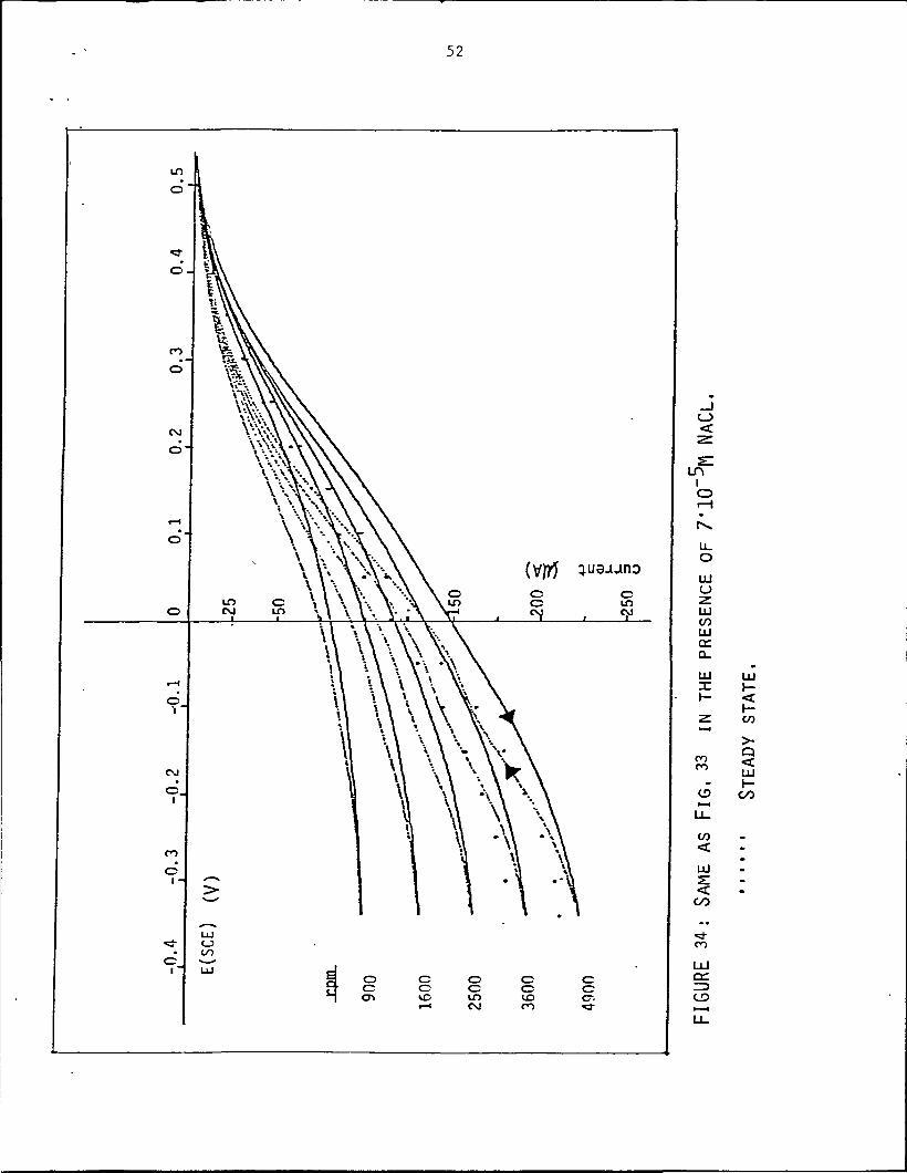
52
C_3I/O
oc01
co
ocIT)CM
CCvoCO
LHIO
oLU
LU
LUo:Q-
LU
COco
CO
LUS
CO
• *
CO
LU\-
co
>-Q<LUI-co

53
IOi—I
CsJ
U_oLU
LUCOLUo:CL
UJX
cooo
CO
UJ
CO
LT>oo
LU01
CD
LU

150
Figure36 : Voltammetry curves for ferric-ferrous couple on
gold disk electrode in acid media containing Br .
Solution: 6mM Fe (CIO,) ' in 0.5M HC10, andf
3mM NaBr and 0.32mM Pb (NO ) . Electrode area:0.458cm'
Sweep rate: A: 10 mv/s, B: 50 mv/s, C: 100 mv/s.

55
w
w
ir
O
CM^
O
mCM\o
oo
oo
oomCN
oo
O O O O O OO O O O O Ot— i CN ro .3- m vo
OO
OOco
01T3O
OOJ
acoco
u3
TJ(U
n
COatgCJ
co
N
CO
o3oo
OllJ C1J
cfl COz
0)c
CN
1
O01
r-l
01f*-i Ci
O
O 4J
OCO
c•H
OJ•O
CU(0(U
PQCO
00
•a-o
coO)
01•ao
u01
oiH
a
oc
o&XI
SCMCO
•O01i-lM-l•HU01D.toCOCO
CO(U
co•H4-1
CO4J
or-<
0)JJcfl

56
B. Effect of the Underpotential Deposition of Bismuth
The plating and stripping of bismuth on gold was studied in perchloric
acid media using a rotating gold disk electrode. The underpotential deposi-
tion of bismuth occurs at potential region between -0.05V and +0.40V vs. SCE.3+ 2+where the Fe(HpO)g /Fe(H20)6 couple undergoes both diffusion and kinetic
controlled reaction. It was found that the underpotential deposition of
bismuth on gold results in a net decrease of the reaction kinetics as compared3+with that on the bare metal for Fe(H20)6 reduction.

57
E (SCE) / V
900 rpm0.6V_ IR.= 0
Figure 38: Voltammetry curves for IPD of bismuth on gold disk electrode.
Voltage window opening experiments. Electrolyte: 0.1M 1C10,,
-5 23.2*10 M Bi203. Electrode area: 0.2 cm . Sweep rate: 10 mv/s.
Rotation rate: 900 rpm

58
A
E(SCE) (V)
SCAN RATE: 10MV/S
fl .5 . 10 . 15 .t(Sec)
B
a,b.c.d.e.f.
0.4 V0.3V0.2 V0. 1 V0.05V0.00V
g.-O.05V
(stepped from 0.8V)
FIGURE 39: UNDERPOTENTIAL DEPOSITION OF Bl ON Au
ROTATING DISK ELECTRODE IN A SOLUTION
0.1M "5, 3,2'10"M Bl203, ELECTRODE
AREA:^0.2CM . ROTATION RATE: 900 RPN.
A, CYCLIC VOLTAKMOGRAM. B, TRANS-IENT EXPERIMENT

59
60
nc
50
40
30
20
10
Bi bulk-1/ 40deposition
E (SCE) / V
Figure 40 : Deposition and Stripping of bismuth on gold disk electrode.
~4Electrolyte: 3.5*10~M Bi^ in 0.1M
10 mv/s. Electrode area: 0.2 cm2.
. Sweep rate:

60
10
15
20
25
t/sec.
a),b).c).d).e).f).g).h).
0.40V0.30V0.20V0.10V0.00V-0.05V-0.10V-0.15V
900 rpm
Figure "1: Current vs. Time curves for gold disk electrode in a solution containing
0.1M IClO and 3.2 10 M Bi 0 upon potential step from 0.8V into indicated
2potential. Rotation rate : 900 rpm. Electrode area: 0.2 cm . I = 0, E =0.8V.
R R

61
Ring(O.SV)
-0.3 -0.2 -0..1 3 0.1 0.2 0.3
f(SCE)/V
-0.3 -0.2 -0.1 0 O.-l 0.2 0.3 0.4 0.5 0.6 0.7 0..8
Disk
FIGURE42 : POLARIZATION CURVE FOR FEt^O)"1" REDUCTIONON ROTATING GOLD RING-DISK ELECTRODE IN
ACIDIC MEDIA, SOLUTION: 3ttM FE(CLO^)^
IN 0.1M HCLO, ROTATION RATE: 900 RPM.
DYNAMIC POLARIZATION . SCAN RATE: lO/W/s,

62
900 rpm
100
80
360
20
-0.4 -0.3 -0.2 -0.1
R i n g ( 0 . 9 V )
0 0.1 0.2 0.3 0.4 0.5 0,6 0.7 n.R n.Q
E(SCE)/ V
-0.4 -0.3 -0.-2 -0.1 0 0.1 0.2 0.3 0.4 0.5 LTo-. 8 ;- 0-9"
E(SCE)/ V
50 Bistripping
n>
900 rpmDisk
FIGURE 43: EFFECT OF Bi. UNDERPOTENTIAL DEPOSITIONON THE REDUCTION OF FECh^O)^" ON GOLD
RING-DISK ELECTRODE, ELECTRODE AREA:
RiNG=DisK^O,2cM2, SOLUTION: 3,2'10~5MBl203, 3.2MM FE(CLO^)3 IN 0.1MROTATION RATE: 900 RPM, RING POTENTIAL: 0, VDYNAMIC POLARIZATION, SCAN RATE: lOMV/s

63
et
3,
TOO
80+jcQJ
b 60
40
20
Ring (0.9V)-0.1,0.0V0.1V
0.4V
0.5V
t/ sec.0 -5 10 15 20 25 30 35 40 45
10 15 20 ?5 3n 35 40 45.t/ sec.
O)
50
100
150
200
250
Disk 900 rpm
0.5V
0.4V-
0.3V
0,2V0.1V
-0.1, 0.0V
Figure 44: Current vs. Time curves for ferric-ferrous couple on gold
ring-disk electrode upon potential step from 0.9V into
indicated potential. Solution: 3.2mM Fe(C10.)3 in 0.1M
HC104. Rotation rate: 900 rpm. Ring potential: 0.9V.2
Electrode area: 0.2 cm .

<3
cuS-3o
80
60
40
20
D.05to-0.3\0.1V
0.2,0.3V
Ring (0.9V), 900 rpm
10 15 20 25 30 35 40 45 t/sec.
t/ sec.
0.3, 0.2V
0.1V0.05V
9o?ifv-0.2, -0.3VJ
Disk , 900 rpm,
Figure 45: Current vs.. Time curves for simultaneous underpotential deposition
of bismuth and Fe(H20)g reduction on gold ring-disk electrode upon
potential step from 0.9V into indicated potential. Solution:3.2mM
Fe(C104)3 , 5MO"5M Bi^ in 0.1M HC104- Rotation rate: 900 rpm.
Ring potential: 0.9V. Electrode area: 0.2 cm2.

65
4. SPECTROSCOPIC STUDIES
A. Time Effects on Solution Composition. (Visible Spectra).
Ultraviolet and visible spectroscopy have been utilized in connection
with the chromium(II)/(III) couple part of NASA's Redox system as a means of
analyzing the solution compositions. These studies have been aimed at deter-
mining the concertration of individual metal complexes at different states
of charge and discharge in an effort to correlate the performance of the
overall electrode with the presence of certain species in solution.
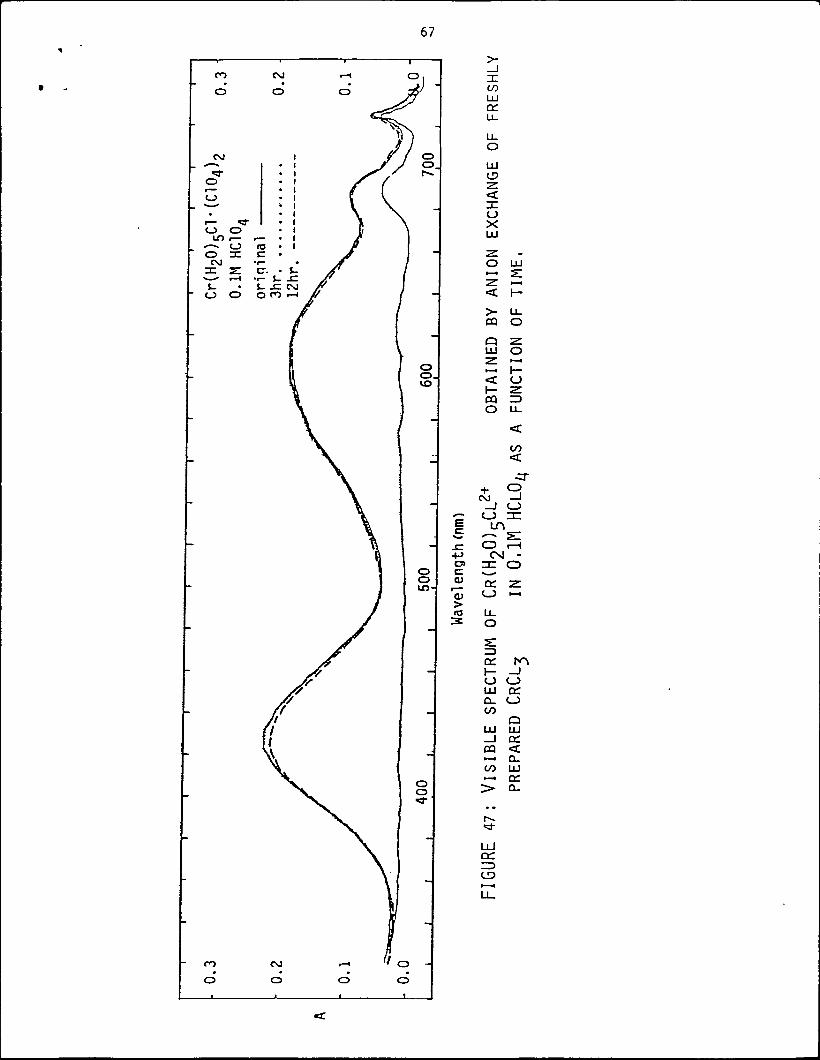
The time dependence of absorption spectra of CrCK solution is shown in
figure 46. It was found that the absorption maximums shift toward shorter2+wavelength with time. However, the spectrum of Cr(H 0) 01 which can be
separated using an ion-exchange column eluting with HC10. does not change
even after 12 hours.(Fig. 47).
B. XPS Measurement on pre-electrolysis Gold Cathode
In order to check out the effects of impurity on the reduction
kinetics of couple, a pre-electrolyzed gold cathode out from the same
supporting electrolyte for the couple is examined by ESCA. No obvious
impurity has been detected, except oxygen and carbon.which exist else
where.(Fig. 48).

66
c c c c c c
'i "i 'i "i 'i 'io o o o o ovo en oo LT> co «—'
.—t i—I .—I CM
CO -O
CDcCD
r—O)
O OCO — •
c_> a.re LU
o:
o u-- o
o
cr --
<_> o< H
21 a:rH 01
- u.C3 LU
ccz>_ UJ
ce
CM
LU
LULL. —•O h-
s: u_ZD ODCH- Z.O OLU —Q_ Hco O
z.LU ra_) u_cq
CO
> <
VO
LU
LU
67
•4JD>CdJ
O)
COLUCC10-
LUO
XOX
O LU
> LUOQ O
Q ZLU O
< u\- -z.O Ll_
<
CO<•3-
+ sCVJ —1
LO
3 ^CSJ -
ce 2
ce Nj- _iO OLU o:o_ <_JCO
QLU LU—I OHCQ <—• O.CO LU—• o:> CL.

68
oCD.CVJ
Lt_O <
CO O—. ZCO •—i>- CO-J !Docc -.\- CO(_> a:uu x_lLU .3-I CM
LUDC 010. O
U.o:LU cI- OU_ _l
Q s:O t— IX O\- - UJ< O Qo o
2 ce
o -dU_ o
uj— IUJ
Q O_J < UJo 2: u
< .— i ceU- Oos: o
UJo:
« Q
f- r>o _Juj oQ- CO
ujQ
CO OQ "Z.UJ <
OOL <H Q:o nUJ H-I <UJ CO
CO
M
0 ujre o 2:a. o =>
o: z> Q —•< >- f-ce x <1 -J
X < Q-
oo<3-
LU