Embed Size (px)
Citation preview


ELECTRO-LEVEL AIR SUSPENSION SYSTEM
GMC MOTORHOMES~
The optional Electro-Level System provides the ability to level the vehicle atcampsite or parking area where the surface is not level. This system can raiseor lower the rear of the vehicle approximately four inches from normal ride
height.
NORMAL OPERATION:
The controls consist of three rocker switches that function to automaticallyor manually level the vehicle. The center rocker switch (TRAVEL) is used foran automatic or hold mode, and the two outer rocker switches (RAISE-LOWER) are
used to raise or lower the vehicle.
DRIVING:
r--
A reminder ligbt in the dash panel is designed to light momentarily any timethe engine is running and the transmission selector lever is moved to "D"(Drive Range). The normal position for the RAISE-LOWER switches should beplaced in the middle position "OFF". The TRAVEL switch should be moved to
"AUTO"
CAMPSITE OR PARKI~Q_AR~:
The two RAISE-LOWER switches may be used as necessary to raise or lower thevehicle. When using Electro-Level at a campsite, the vehicle engine need notbe running to operate the system; however, the ignition switch must be in the
"ON" or "ACCESSORY" position.
"RAISE" -With a rocker switch in this position, the appropriate side of thevehicle will raise to any desired position, up to a maximum of approximatelyfour inches above normal ride height. When desired height is reached, return
rocker switch to "OFF" position.
"LOWER" -With a rocker switch in this position, the appropriate side of thevehicle will lower a maximum of approximately four inches below the normal rideheight. In order to maintain a desired height, return rocker switch to "OFF"
position.
~

It is possible that the air compressor may operate for a shortperiod when a rocker switch is in "LOWER" position.
NOTE:
IMPORTANT: When both sides of the vehicle have been leveled, be sure theTRAVEL switch is moved to "HOLD" and turn ignition switch to"OFF".
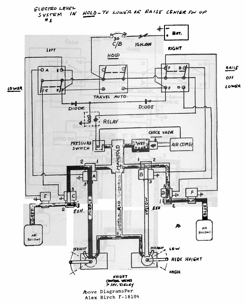
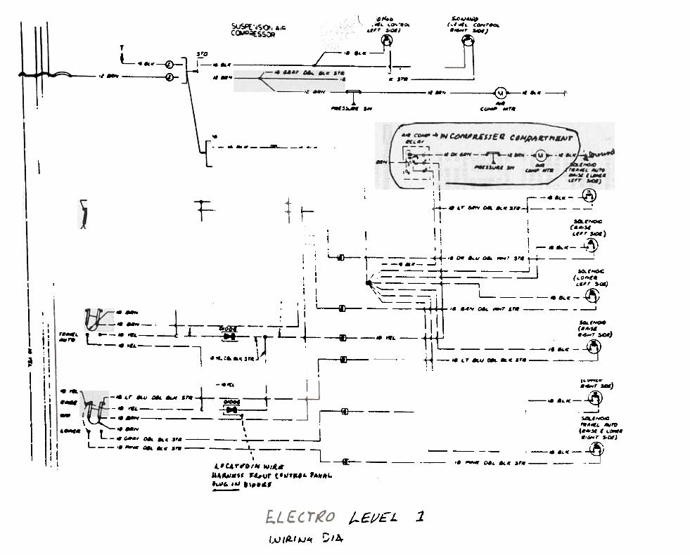
(See Attached Electro-Level Air System Schematic)..Q~ONENTS AND THEIR OPERATION.:
The hardware for the system is basically the same as the former system with theaddition of six electrically actuated air solenoids. These solenoids givepositive air flow or stoppage; whichever is called for. Four of the solenoids(two per side) are three-way and two (one per side) are two-way.
All components except the control panel, air bellows and height control valves,(located as before) are located in the lower cabinet of the closet module. Theassembly consisting of the air compressor, pressure switch, check valve, wettank connecting fittings, and solenoids is referred to as the air control module.
AIR FLOW
The main function of this system is to provide air to the bellows, and maintaina proper height with a minimum possibility of a leak-down. This is accomplishedby the two-way solenoids, "E" and "F". The purpose of these solenoids in anormal operating condition; i.e. while the vehicle is operating and the "TRAVEL"switch is in "HOLD" with the "RAISE-LOWER" switches in the center "OFF" positionis to remain closed, trapping air in the bellows and isolating the bellows fromthe rest of the system. This means the only possible areas of leakage will bethe bellows themselves, the fitting on the bellows, the fittings at the solenoidsor the air line running between. The rest of the system is not in any wayfunctional. This same air flow situation exists when the vehicle is parked andthe key is off.
When the vehicle is operating with the "TRAVEL" switch in "AUTO", solenoids "E"and "F" are open. This allows air to flow from the compressor through the
. f . d " A " " c " d " E"th 1 fthe1ght control valve and urther through soleno1 s , an on e e
side. On the right side, it will flow through solenoids "B", "D" and "F" tothe bellows. Height of the vehicle in the "AUTO" mode will simply be regulatedby the height control valves. The three-way solenoids will allow air to passfrom the No.3 port to the No.2 port. This is the normal air flow of thesevalves when they are not energized.
If a vehicle is put in the "RAISE" position by use of the "RAISE-LOWER" switch,air flow is a little different. System pressure air no longer goes throughvalves "A" or "B" from the No.3 port to the No.2 port. Instead, this passageis closed and air flows from the No. 1 port to the No.2 port. This means theheight control valve is now taken out of the system and air going throughsolenoids "A" or "B" is regulated only by the rocker switch on the dash panel.Air will continue through solenoids "c" and "E" to the left side or "D" and
"F" on the right side.
2

To lower the system, the "RAISE-LOWER" switches on the dash will be set in the"LOWER" position energizing solenoids "c" or "D" which causes the normal passageof air between the No.3 port to the No.2 port to be altered. Instead, thesolenoid opens the passage between the No.2 and No. 1 ports which goes to theatmosphere allowing the vehicle to lower by expelling air.
1"""""'-
OFF-ROAD OPERATION:
In order to gain maximum ground clearance both "RAISE-LOWER" switches should beplaced in the "RAISE" position. It is recommended that a speed of 15 mph shouldnot be exceeded since the air suspension in this position has maximum pressure
supplied.
~~NCY OPERATION :
In the event of total air loss for any reason, the vehicle may be driven at aspeed of 5-15 mph (depending on road surface) with the rear of the vehicle inthe fully "DOWN" position. Care should be exercised since ground clearanceat the rear will be at a minimum. Vehicle should be taken to nearest dealer.
Depending on the type of failure, it may be possible to add air to the rearsuspension at the wet tank (shop air fill valve located on tank) at a localgas station. (DO NOT EXCEED 120 PSI). Be sure the engine is running or theignition switch is turned to "ON" or "ACCESSORY" position, and the outerrocker switches in "RAISE" position until vehicle is leveled. Then move"RAISE-LOWER" switches to "OFF" and "TRAVEL" switch to "HOLD".
~
MAINTENANCE:
No routine maintenance is required on the Electro-Level System other thandraining moisture in the wet tank. Expell moisture into cup or rag.
~
3

IIIIIIL- rIII
EX
HA
US
T
""
HE
IGH
T
CO
NT
RO
l V
AlV
E
ELE
CT
RO
-LEV
EL
AIR
S
YS
TE
M
3A P
RE
SS
UR
E
~
~
l
~
la4 9~z<t
~
~
WE
T
TA
NK
~
-iXH
AU
ST
=l
HE
IGH
T
CO
NT
RO
L V
ALV
E
-IIIIIIIIIIIIIIIII
_J

RAiSER~IS'
-DIF0"
~OW~
4-OW~
Alex Birch F-IB1O4
5
f'L~CTJZO L..E&J£'"I-
S V S "rE'" 1-1 I "
...1.
"'AIS~L()UI£1l 1£Ho/../) -TU--
l.G N'~~ .rJ,..! "p
~- ;..~cia IG111.-
~IGUTtl"
HOtP-
H.-:1~A'5f
-:' rY--.,;;J
- aIt
r'-.,
OFF~ t--~
Lowa~~, DClOW~ G).~
,- ~
-~-1Mvta. .AUTO .
.~- -I~
D~ODE~ .D'O~ ---
JJ -fiLAY -
--
--c;-
.Q' 1
~".~.: .6
I,.CL' ,',..~
~I I" I
I:~U.4,~.i~,
:. I
~:-~.I
pRfSSu¥'WI'C..
I 2,"c_-2_'
.~.
18I~
---1
.Ir
~ 0+,
:1~~ ~r;:-:-: : ---a E X II.
-.-I
t
1.
~
... Ala
."'O~fA~.
~LLO..'
.-~ "_."'A ~ Ow
I" \
..RIO£ HII'HT
l /"~ ...GH
.,'"
~".'GNT
cwr ~ .-.ws
.,.. ",('. 'D'"'~Y
/t)ove DiagramsPer
Alex Birch F-1B1O4
6
CNKK VAl..
i

.-
(;~I{[CTIONPUS~MJLL LAU~l--
joIl(WL~MI. Ellm.".t. .Ir 1_llk.
:. ( lllIlIl"'L. Dlr I&:uk.!. l..k In ..r b~lllIw..l. l~.k lIt .Ir 111~1o IJvlw.'VII
a,ellowl .nd IOlultOId.). leek In 2-w.y lolulluld.
L~LETL UKl'Af<IIAL L(JS~ CI="A"~ WI' H TKAVt:L~WlrL:H IN ~D...
). S.rvlce or repllfCtl IOlenoId.
I. Ellmllllfte Mlr lelfk.
'. EJlmInut~ u/r leak.(:OM-'LI::TL ORU(AUUAL LOSS C»""All( UV[t(NI~T ATLAM)~IGHT WlfHI~I T I(JN ()--f" .
J. Eliminate air leak.
14. Service or repl~c~ solellOId.
1. L8ak .t .Ir bellow..2. L.ak in .Ir Ilr.! u\:tweul!
ml.noid ~ b.llowl.}. L..k .t fittlnq UctWIJ~'1
ml.nold IInd "Ir line orI b.llo- ~ .Ir li,..
4. Defective 2.WMy IUlenoId
, v81ve.
I. ElimInDtt! IIlr 11:1Ik. Note: Vehicle
itX)Uld Uu WC.'rwL~IJ wit Ii travel
Iwitch In
.Air leak in Iyltelrl.ICuM..L£TE UKI)AI(TIAI- l(JSS (yo AII{IIWITH Tt(AV[L SWITCH!:IN "AUTO", I~ITION ,
ON. (CUt.,f>Ht:55Qt{I(~S lUOfK(- I
1UULNrL y). I
:. Service or replace valve.2. DefecllYe ~ight contrul
YBIYe.
1. Compressor nul upL:r..lIIVj.2. D~f~cltv~ cUfIlrul ~wilclt.). Dcf~r:livc I>re:;:.ur~ awllL-h.4. Dl:f~r:livl: dt()lJ~.
~. Defecllve wlrir\(j.
rl(AVlL SWITCH IN
"AU1U". NOTHING
I tl\"I}LN5.
I. Chcck f~l:d Mt IJr~ wire.
2. f{.,~loce switch.,. Hl:pl;jf.e ~wltl:h.4. (;ht.'Ck dlodt:. 1{~I'lace us required.S. Check wirir\9 ..id cleclrlc81 con-
nec:ll(MIS.6. R~pliJce rclity.7. Servicc or rcplMce solenuid vulves.
K. [11",lllule ..Ir leiJk.9. (1Imlr...t~ le:Jk.
6. Check relay.7. ~fective soleItUId v..lvt!s.
B. LeMk Mt Mtr lJ.,lluw~9. LeMk in .or Ii'.'..
i. CJlmInnlt: IIIr It:uk.:. Prupcrly If~lall :;uJerl&Jid vitlwe.1. Lt!ak in air Ilncs.
2. SOIHnoId VMlvH~ jJlUlI,lJ.,diocorrectly. (ItAIS[ ~ltJ-
FVJids.),. faulty Ha-D 5ult!nuld vulvt!~
4. faulty HAISC sul~nold.
LI/ r 01{ /{IGHT~jWII CH IN .~AISL..l'O51110N. VI~HJCLEI)IJ 'iN'f RAI~[.L:U~I{lSSO/{ I{~S.
). f ~Ity L'unlrul SWilo:II.6. Dt:1~tlv&: wlrlfllj lJt:lW.'O:II
control Iwilclo .-td ~1t:'.ultJ
). 5eryice fX" replilc~ YaIYt!s.i. f ollow bench clleck of solenoid.
~"ryice ur reJ'I ~ w. ne=t:~5S..ry.
.,. '(eplace ,witch.6. C'M:ck wlrllMJ ;JIld ~1t:ctrIcMI
COI W\t!C ti OfIS.
Lit r I II( t<IGHT..WI'tIIIN"1(AI~L"I.U~IIIUN. V[HIL:L£UOCSN'T KAISt.:.CUMPt{I::SSOK RLJIoIS
01:1 rUt( KIGHT
'.WI rl.::H IN ~AI5("
IJu~1 fIUN. VlHICLE
IJIJ.- '.1'-1" ~AI5[.(:UI.t-'I<I-S'jOK NOT
U'LI(AIIN(.;.
1. Motor br~hes or commutatorworn ()Ul. K~pliJce motor.
2. Cli!iJ/l cunt4Cts or repl»ce rt:l;}y.J. Pllled COllt¥Ct.. I~eplace pre5~ure
swilch.4. ChiJr9~ ur r~plilce 8UtOlnutIve
blltt~ry.~. RepliJCe dIOlJe.6. Check WIMr\tJ ;JIIl1 i!lectricill
COfVleCtIU/l5.
I. Open circuit In cUII'prL::i:;ur
",utor.2. I)efectlve relilY.}. Open in pre..ure .wllcll.
4. O..ttery IS\dI:rcIIO!rlJl°tJ.
5. Defective diode.6. Detectlvt: wirll'llJo (COIII-
pr~.sor feed O!t IJroulltJ wIrL:
not co~cted.)7. Dp~" circuit lJr~O!kL:r °
7. Cht:rk fl)r ColU:it: I)f open circuit
brt:itker. f{e:;t:t.U. 1{t:IJlacl! switch.
tI. f MUlty cuntrol 5Wilc:/I.
Corr~l:lJy .115l"JI :.ulcno.d VjjJVl!s.1. LOW[H ~1."IUIU I..t::.
lrw::orrectJy plumlJ.'.J.l. UlltJerchifrl}t:U tJ..ll.'ry.}. Qef&tCtIve wlrlf1(j.
4. Op&J1\ circuit tJrt!..k&:r
2. ChurIJt: or r~pl"c~ u..ttt:ry.}. CheCk wIrlncJ and t:JectrlcMJ con-
nectlunS.4. f,ntJ c"u»c for ~t!n cirL:uit ureaker.
Re~t.'J. Serylct: or rt!plilcc solenoId yulyes.
to. Repl"cc swltcll.~. Iklt:cliv~ :o()lIJnuld Villvt':.
6. Dell:cltvt: control SWlt.:",
7
8
fr..m .he dN 01
BASIL BICKEL
~MOTOAHOMES INTEAHATIOHAL
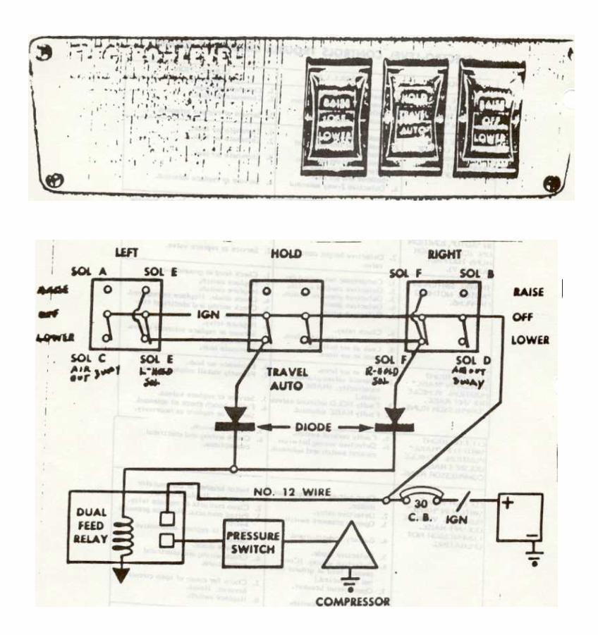
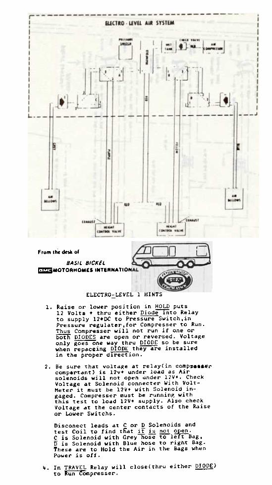
ELECTRO-LEVEL 1 HINTS
1. Raise or lower position in HOLD puts12 Volts + thru either Diode-rnto Relayto supply 12.DC to Pressure-Switch,inPressure regulater,for Compresser to Run.Thus Compresser will not run if one orbOth DIODES are open or rever5ed. Voltageonly goes one way thru DIOD£ so be surewhen repaceing DIODL they-are installedin the proper dIreCtion .
2. Be sure ~hat vol~a~e a~ relay(in compll...li.rcomp&rtant) is 12v+ under load as Airsolenoids will not open under l2V+. CheckVoltage at Solenoid connecter With volt-Meter it must be l2V+ with Solenoid in-gaged. Compresser must be runnin~ withthis test to load 12V+ supply. Also checkVoltage at the center contacts of the Raise
or Lower Switchs.
Disconect leads at Cor D Solenoids andtest Coil to find that it i~ not ~.C is Solenoid with Grey~ose ro-left Bag.D is Solenoid with Blue hose to right Bag.These are to Hold the Air in the Bags wh~n
Power is oft.
~. In TRAVEL Relay will close(thru either DIODE)to Run Compresser. -
9
E ~ 't. .1'
\.-)
... ~
~ ~ ~\ t-.. ~
~
I. -
I I
j.
--r-
4'n
I ~
.
I t
I i
I
-.II-
-.,. If'
'~~
, 'II
i
.,I
: :
Iti
ill
~
I ~ i
~
II. -
_uf~I'
i,.
~-.
~
1I
.t'
~
I~
i! II
I I
r(Ll
.,
I I
I I
-..Ir
I i
I9
I
I; I
I I r
.I 1 I
~ I
, ~ ~ ~ .I
I I, ..
I.,.
,.
~A I
.I --
ii!~
l~
'\ti!
~;~
;I ~
!.t!la
-
~
-I 6 ~
~t
j~i .. l ~ ~ "' - ~ , i ~ ~ ~ "'
I' .., I,
~
I I
. 0
, . ~
-"i
i i
j !
j
~~
t . ~ i .. ~ w .
10..-~
-~.
It.
."
-t
._.
I
~.
.I.
..~
..
t-
-"
.~
1,(
i i,
,
Ilrl~
l..j+
-::
11,1
1 ~
II,
~c
..&&
&
,.-
~i
~~
,.=
t~
'ri5
ii~
~,
I. !
, I
t ~
II'
-j :
~
~ A
~ I
I i
iltt
Ii
II
+1' , I
--iI
,-I
- I I IJ &
I ~
I; I ~
1 ,
.I I
Ji
I I
I I
I. , -
..I
--J
T.-
:I
I..
I, ~
~
, :
~ I
,J I
--~
-J~
--
--. _.-
I ~ I
.~ i I I
t I . -
I~
. i
.~
,
.- ~
" tt . .A , - 1-1
.
.;-t'
:1)
t ~
t
It' ~.. J-
tj i,. ~ I I
j ,
~ J
J ,
I I
II
I
I ~
i
~
rt~
L -"
't !
, _.rL
~.-
+-
JI
I t
f--
f ~
-.
.
j1
I n'n
1JI
~
1111
11;1
:;-
-J;iJ
I ~I
11,1
'
!f-tt.
.=t-
:=:=
--
_1
H~
-t
:.=
---t
:.:
.::--
-=
-J
~
I r-
L-
., t
&
.
Jli
~
I
~
I i
I~
~
I
J~
i
r
Ii
i ir---f
'
It
ill
~
~~
..,
, M
.
J~
M
l".
.~
..~
.~
.L
.
~I
Ii
11-r
ll
(~I
IL
1-
1 ~
~
11'
I
I.I.
.
I.,
I;,
, .I
~~
I~
~
-.
Ii
~';'
~
I ~
!.I
I I,.
,. ~
."
!
it::"
,ti'
l;b
~!~
-~
;~1
I_~
!i'
-~
i~i
~l.~
!
5 _i
~ J
r A t ~ +
~a .. .t ~
~
I \ , i , ! / I , I ,. ~ - I.