Embed Size (px)
Citation preview
Electricity and MagnetismCapacitors and Dielectrics
Lana Sheridan
De Anza College
Oct 20, 2015
Last time
• circuits
• capacitors in series and parallel
Warm Up Question
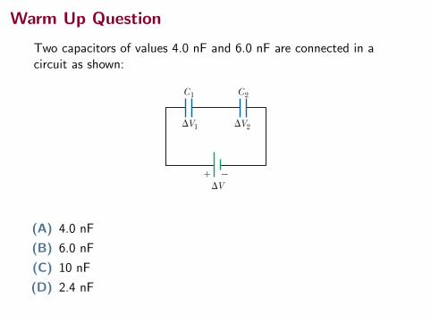
Two capacitors of values 4.0 nF and 6.0 nF are connected in acircuit as shown:
784 Chapter 26 Capacitance and Dielectrics
the individual capacitances. Statement (2) makes sense because we are essentially combining the areas of all the capacitor plates when they are connected with con-ducting wire, and capacitance of parallel plates is proportional to area (Eq. 26.3).
Series CombinationTwo capacitors connected as shown in Figure 26.8a and the equivalent circuit dia-gram in Figure 26.8b are known as a series combination of capacitors. The left plate of capacitor 1 and the right plate of capacitor 2 are connected to the termi-nals of a battery. The other two plates are connected to each other and to nothing else; hence, they form an isolated system that is initially uncharged and must con-tinue to have zero net charge. To analyze this combination, let’s first consider the uncharged capacitors and then follow what happens immediately after a battery is connected to the circuit. When the battery is connected, electrons are transferred out of the left plate of C1 and into the right plate of C 2. As this negative charge accumulates on the right plate of C 2, an equivalent amount of negative charge is forced off the left plate of C 2, and this left plate therefore has an excess positive charge. The negative charge leaving the left plate of C 2 causes negative charges to accumulate on the right plate of C1. As a result, both right plates end up with a charge 2Q and both left plates end up with a charge 1Q . Therefore, the charges on capacitors connected in series are the same:
Q 1 5 Q 2 5 Q
where Q is the charge that moved between a wire and the connected outside plate of one of the capacitors. Figure 26.8a shows the individual voltages DV 1 and DV 2 across the capacitors. These voltages add to give the total voltage DVtot across the combination:
DVtot 5 DV1 1 DV2 5Q 1
C11
Q 2
C 2 (26.9)
In general, the total potential difference across any number of capacitors connected in series is the sum of the potential differences across the individual capacitors. Suppose the equivalent single capacitor in Figure 26.8c has the same effect on the circuit as the series combination when it is connected to the battery. After it is fully charged, the equivalent capacitor must have a charge of 2Q on its right plate and a charge of 1Q on its left plate. Applying the definition of capacitance to the circuit in Figure 26.8c gives
DVtot 5Q
C eq
! "
C2
#V
C1#V1 #V2
#V
C1 C2
#V1 #V2!Q "Q !Q "Q
! "#V
C2Ceq C1 11 1
$ !
! "
A pictorial representation of two capacitors connected in series to a battery
A circuit diagram showing the two capacitors connected in series to a battery
A circuit diagram showing the equivalent capacitance of the capacitors in series
a b c
Figure 26.8 Two capacitors connected in series. All three dia-grams are equivalent.
(A) 4.0 nF
(B) 6.0 nF
(C) 10 nF
(D) 2.4 nF

Warm Up Question
Two capacitors of values 4.0 nF and 6.0 nF are connected in acircuit as shown:
784 Chapter 26 Capacitance and Dielectrics
the individual capacitances. Statement (2) makes sense because we are essentially combining the areas of all the capacitor plates when they are connected with con-ducting wire, and capacitance of parallel plates is proportional to area (Eq. 26.3).
Series CombinationTwo capacitors connected as shown in Figure 26.8a and the equivalent circuit dia-gram in Figure 26.8b are known as a series combination of capacitors. The left plate of capacitor 1 and the right plate of capacitor 2 are connected to the termi-nals of a battery. The other two plates are connected to each other and to nothing else; hence, they form an isolated system that is initially uncharged and must con-tinue to have zero net charge. To analyze this combination, let’s first consider the uncharged capacitors and then follow what happens immediately after a battery is connected to the circuit. When the battery is connected, electrons are transferred out of the left plate of C1 and into the right plate of C 2. As this negative charge accumulates on the right plate of C 2, an equivalent amount of negative charge is forced off the left plate of C 2, and this left plate therefore has an excess positive charge. The negative charge leaving the left plate of C 2 causes negative charges to accumulate on the right plate of C1. As a result, both right plates end up with a charge 2Q and both left plates end up with a charge 1Q . Therefore, the charges on capacitors connected in series are the same:
Q 1 5 Q 2 5 Q
where Q is the charge that moved between a wire and the connected outside plate of one of the capacitors. Figure 26.8a shows the individual voltages DV 1 and DV 2 across the capacitors. These voltages add to give the total voltage DVtot across the combination:
DVtot 5 DV1 1 DV2 5Q 1
C11
Q 2
C 2 (26.9)
In general, the total potential difference across any number of capacitors connected in series is the sum of the potential differences across the individual capacitors. Suppose the equivalent single capacitor in Figure 26.8c has the same effect on the circuit as the series combination when it is connected to the battery. After it is fully charged, the equivalent capacitor must have a charge of 2Q on its right plate and a charge of 1Q on its left plate. Applying the definition of capacitance to the circuit in Figure 26.8c gives
DVtot 5Q
C eq
! "
C2
#V
C1#V1 #V2
#V
C1 C2
#V1 #V2!Q "Q !Q "Q
! "#V
C2Ceq C1 11 1
$ !
! "
A pictorial representation of two capacitors connected in series to a battery
A circuit diagram showing the two capacitors connected in series to a battery
A circuit diagram showing the equivalent capacitance of the capacitors in series
a b c
Figure 26.8 Two capacitors connected in series. All three dia-grams are equivalent.
(A) 4.0 nF
(B) 6.0 nF
(C) 10 nF
(D) 2.4 nF←
Overview
• practice with capacitors in circuits
• energy stored in a capacitor
• dielectrics
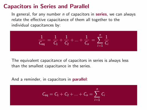
Capacitors in Series and ParallelIn general, for any number n of capacitors in series, we can alwaysrelate the effective capacitance of them all together to theindividual capacitances by:
1
Ceq=
1
C1+
1
C2+ ... +
1
Cn=
n∑i=1
1
Ci
The equivalent capacitance of capacitors in series is always lessthan the smallest capacitance in the series.
And a reminder, in capacitors in parallel:
Ceq = C1 + C2 + ... + Cn =
n∑i=1
Ci
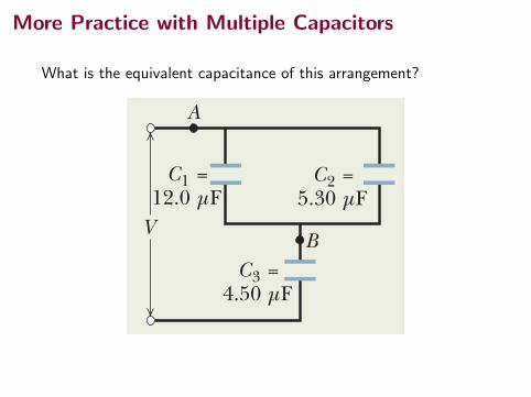
More Practice with Multiple Capacitors
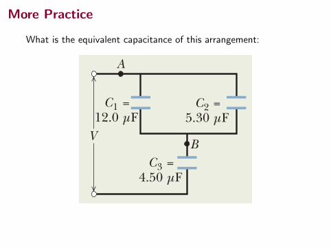
What is the equivalent capacitance of this arrangement?
Sample Problem
charge, capacitor 3 is not in series with capacitor 1 (or ca-pacitor 2).
Are capacitor 1 and capacitor 2 in parallel? Yes.Their top plates are directly wired together and theirbottom plates are directly wired together, and electricpotential is applied between the top-plate pair and thebottom-plate pair. Thus, capacitor 1 and capacitor 2 arein parallel, and Eq. 25-19 tells us that their equivalent ca-pacitance C12 is
C12 ! C1 " C2 ! 12.0 mF " 5.30 mF ! 17.3 mF.
In Fig. 25-10b, we have replaced capacitors 1 and 2 withtheir equivalent capacitor, called capacitor 12 (say “onetwo” and not “twelve”). (The connections at points A and Bare exactly the same in Figs. 25-10a and b.)
Is capacitor 12 in series with capacitor 3? Again apply-ing the test for series capacitances, we see that the chargethat shifts from the top plate of capacitor 3 must entirely goto the bottom plate of capacitor 12. Thus, capacitor 12 andcapacitor 3 are in series, and we can replace them with theirequivalent C123 (“one two three”), as shown in Fig. 25-10c.
Capacitors in parallel and in series
(a) Find the equivalent capacitance for the combination ofcapacitances shown in Fig. 25-10a, across which potentialdifference V is applied.Assume
C1 ! 12.0 mF, C2 ! 5.30 mF, and C3 ! 4.50 mF.
KEY I DEA
(a)
C1 =12.0 µF
C2 =5.30 µF
C12 =17.3 µF
C123 =3.57 µF
C3 =4.50 µF
C3 =4.50 µF
A
BB
A
(b) (c)
V
C12 =17.3 µF
C3 =4.50 µF
q3 =44.6 µC
( f )
12.5 V
VC123 =
3.57 µFV123 =12.5 V
(d)
12.5 VC123 =
3.57 µF
q123 =44.6 µC
q12 =44.6 µC
C12 =17.3 µF
V12 =2.58 V
V3 =9.92 V
C3 =4.50 µF
q3 =44.6 µC
(g)
12.5 V
q12 =44.6 µC
V123 =12.5 V
(e)
12.5 VV
(h)
C1 =12.0 µF
V1 =2.58 V
V2 =2.58 V
V3 =9.92 V
C2 =5.30 µF
C3 =4.50 µF
q3 =44.6 µC12.5 V
(i )
C1 =12.0 µF
q1 =31.0 µC
q2 =13.7 µC
V1 =2.58 V
V2 =2.58 V
V3 =9.92 V
C2 =5.30 µF
C3 =4.50 µF
q3 =44.6 µC12.5 V
We first reduce thecircuit to a singlecapacitor.
Next, we workbackwards to thedesired capacitor.
Series capacitors andtheir equivalent havethe same q (“seri-q”).
Parallel capacitors andtheir equivalent havethe same V (“par-V”).
Applying V = q/C yieldsthe potential difference.
Applying q = CVyields the charge.
Applying q = CVyields the charge.
The equivalent ofparallel capacitorsis larger.
The equivalent ofseries capacitorsis smaller.
66525-4 CAPACITORS I N PARALLE L AN D I N S E R I E SPART 3
HALLIDAY REVISED
Fig. 25-10 (a) – (d) Three capacitors are reduced to one equivalent capacitor. (e) – (i)Working backwards to get the charges.
A
Any capacitors connected in series can be replaced withtheir equivalent capacitor, and any capacitors connected inparallel can be replaced with their equivalent capacitor.Therefore, we should first check whether any of the capaci-tors in Fig. 25-10a are in parallel or series.
Finding equivalent capacitance: Capacitors 1 and 3 areconnected one after the other, but are they in series? No.The potential V that is applied to the capacitors producescharge on the bottom plate of capacitor 3. That chargecauses charge to shift from the top plate of capacitor 3.However, note that the shifting charge can move to thebottom plates of both capacitor 1 and capacitor 2.Because there is more than one route for the shifting
halliday_c25_656-681v2.qxd 23-11-2009 16:32 Page 665
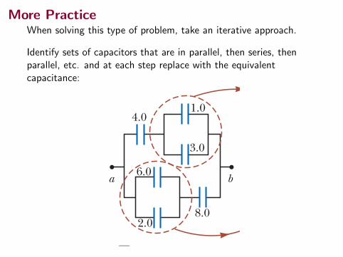
More PracticeWhen solving this type of problem, take an iterative approach.
Identify sets of capacitors that are in parallel, then series, thenparallel, etc. and at each step replace with the equivalentcapacitance:
26.3 Combinations of Capacitors 785
Substituting this result into Equation 26.9, we have
Q
C eq5
Q 1
C 11
Q 2
C 2
Canceling the charges because they are all the same gives
1
C eq5
1C1
11
C 2 1series combination 2
When this analysis is applied to three or more capacitors connected in series, the relationship for the equivalent capacitance is
1
C eq5
1C 1
11
C 21
1C3
1 c 1series combination 2 (26.10)
This expression shows that (1) the inverse of the equivalent capacitance is the alge-braic sum of the inverses of the individual capacitances and (2) the equivalent capacitance of a series combination is always less than any individual capacitance in the combination.
Q uick Quiz 26.3 Two capacitors are identical. They can be connected in series or in parallel. If you want the smallest equivalent capacitance for the combination, how should you connect them? (a) in series (b) in parallel (c) either way because both combinations have the same capacitance
�W Equivalent capacitance for capacitors in series
Example 26.3 Equivalent Capacitance
Find the equivalent capacitance between a and b for the combination of capacitors shown in Figure 26.9a. All capacitances are in microfarads.
Conceptualize Study Figure 26.9a carefully and make sure you understand how the capacitors are connected. Verify that there are only series and parallel connec-tions between capacitors.
Categorize Figure 26.9a shows that the circuit contains both series and parallel connections, so we use the rules for series and parallel combinations discussed in this section.
Analyze Using Equations 26.8 and 26.10, we reduce the combination step by step as indicated in the figure. As you follow along below, notice that in each step we replace the combination of two capacitors in the circuit diagram with a single capacitor having the equivalent capacitance.
S O L U T I O N
4.04.0
8.08.0
ba
4.0
ba
2.0
6.0 ba
4.0
8.0
ba
2.0
6.0
3.0
1.0
a b c d
Figure 26.9 (Example 26.3) To find the equivalent capacitance of the capacitors in (a), we reduce the various combinations in steps as indicated in (b), (c), and (d), using the series and parallel rules described in the text. All capacitances are in microfarads.
The 1.0-mF and 3.0-mF capacitors (upper red-brown circle in Fig. 26.9a) are in parallel. Find the equivalent capacitance from Equation 26.8:
Ceq 5 C1 1 C 2 5 4.0 mF
The 2.0-mF and 6.0-mF capacitors (lower red-brown circle in Fig. 26.9a) are also in parallel:
Ceq 5 C1 1 C 2 5 8.0 mF
The circuit now looks like Figure 26.9b. The two 4.0-mF capacitors (upper green circle in Fig. 26.9b) are in series. Find the equivalent capacitance from Equation 26.10:
1
C eq5
1C 1
11
C 25
14.0 mF
11
4.0 mF5
12.0 mF
C eq 5 2.0 mF
continued
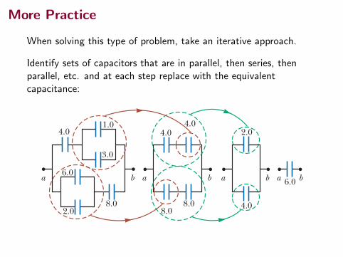
More Practice
When solving this type of problem, take an iterative approach.
Identify sets of capacitors that are in parallel, then series, thenparallel, etc. and at each step replace with the equivalentcapacitance:
26.3 Combinations of Capacitors 785
Substituting this result into Equation 26.9, we have
Q
C eq5
Q 1
C 11
Q 2
C 2
Canceling the charges because they are all the same gives
1
C eq5
1C1
11
C 2 1series combination 2
When this analysis is applied to three or more capacitors connected in series, the relationship for the equivalent capacitance is
1
C eq5
1C 1
11
C 21
1C3
1 c 1series combination 2 (26.10)
This expression shows that (1) the inverse of the equivalent capacitance is the alge-braic sum of the inverses of the individual capacitances and (2) the equivalent capacitance of a series combination is always less than any individual capacitance in the combination.
Q uick Quiz 26.3 Two capacitors are identical. They can be connected in series or in parallel. If you want the smallest equivalent capacitance for the combination, how should you connect them? (a) in series (b) in parallel (c) either way because both combinations have the same capacitance
�W Equivalent capacitance for capacitors in series
Example 26.3 Equivalent Capacitance
Find the equivalent capacitance between a and b for the combination of capacitors shown in Figure 26.9a. All capacitances are in microfarads.
Conceptualize Study Figure 26.9a carefully and make sure you understand how the capacitors are connected. Verify that there are only series and parallel connec-tions between capacitors.
Categorize Figure 26.9a shows that the circuit contains both series and parallel connections, so we use the rules for series and parallel combinations discussed in this section.
Analyze Using Equations 26.8 and 26.10, we reduce the combination step by step as indicated in the figure. As you follow along below, notice that in each step we replace the combination of two capacitors in the circuit diagram with a single capacitor having the equivalent capacitance.
S O L U T I O N
4.04.0
8.08.0
ba
4.0
ba
2.0
6.0 ba
4.0
8.0
ba
2.0
6.0
3.0
1.0
a b c d
Figure 26.9 (Example 26.3) To find the equivalent capacitance of the capacitors in (a), we reduce the various combinations in steps as indicated in (b), (c), and (d), using the series and parallel rules described in the text. All capacitances are in microfarads.
The 1.0-mF and 3.0-mF capacitors (upper red-brown circle in Fig. 26.9a) are in parallel. Find the equivalent capacitance from Equation 26.8:
Ceq 5 C1 1 C 2 5 4.0 mF
The 2.0-mF and 6.0-mF capacitors (lower red-brown circle in Fig. 26.9a) are also in parallel:
Ceq 5 C1 1 C 2 5 8.0 mF
The circuit now looks like Figure 26.9b. The two 4.0-mF capacitors (upper green circle in Fig. 26.9b) are in series. Find the equivalent capacitance from Equation 26.10:
1
C eq5
1C 1
11
C 25
14.0 mF
11
4.0 mF5
12.0 mF
C eq 5 2.0 mF
continued
More Practice
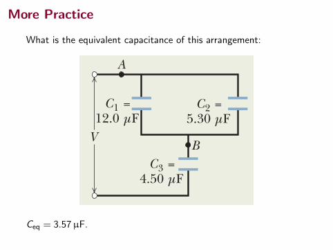
What is the equivalent capacitance of this arrangement:
Sample Problem
charge, capacitor 3 is not in series with capacitor 1 (or ca-pacitor 2).
Are capacitor 1 and capacitor 2 in parallel? Yes.Their top plates are directly wired together and theirbottom plates are directly wired together, and electricpotential is applied between the top-plate pair and thebottom-plate pair. Thus, capacitor 1 and capacitor 2 arein parallel, and Eq. 25-19 tells us that their equivalent ca-pacitance C12 is
C12 ! C1 " C2 ! 12.0 mF " 5.30 mF ! 17.3 mF.
In Fig. 25-10b, we have replaced capacitors 1 and 2 withtheir equivalent capacitor, called capacitor 12 (say “onetwo” and not “twelve”). (The connections at points A and Bare exactly the same in Figs. 25-10a and b.)
Is capacitor 12 in series with capacitor 3? Again apply-ing the test for series capacitances, we see that the chargethat shifts from the top plate of capacitor 3 must entirely goto the bottom plate of capacitor 12. Thus, capacitor 12 andcapacitor 3 are in series, and we can replace them with theirequivalent C123 (“one two three”), as shown in Fig. 25-10c.
Capacitors in parallel and in series
(a) Find the equivalent capacitance for the combination ofcapacitances shown in Fig. 25-10a, across which potentialdifference V is applied.Assume
C1 ! 12.0 mF, C2 ! 5.30 mF, and C3 ! 4.50 mF.
KEY I DEA
(a)
C1 =12.0 µF
C2 =5.30 µF
C12 =17.3 µF
C123 =3.57 µF
C3 =4.50 µF
C3 =4.50 µF
A
BB
A
(b) (c)
V
C12 =17.3 µF
C3 =4.50 µF
q3 =44.6 µC
( f )
12.5 V
VC123 =
3.57 µFV123 =12.5 V
(d)
12.5 VC123 =
3.57 µF
q123 =44.6 µC
q12 =44.6 µC
C12 =17.3 µF
V12 =2.58 V
V3 =9.92 V
C3 =4.50 µF
q3 =44.6 µC
(g)
12.5 V
q12 =44.6 µC
V123 =12.5 V
(e)
12.5 VV
(h)
C1 =12.0 µF
V1 =2.58 V
V2 =2.58 V
V3 =9.92 V
C2 =5.30 µF
C3 =4.50 µF
q3 =44.6 µC12.5 V
(i )
C1 =12.0 µF
q1 =31.0 µC
q2 =13.7 µC
V1 =2.58 V
V2 =2.58 V
V3 =9.92 V
C2 =5.30 µF
C3 =4.50 µF
q3 =44.6 µC12.5 V
We first reduce thecircuit to a singlecapacitor.
Next, we workbackwards to thedesired capacitor.
Series capacitors andtheir equivalent havethe same q (“seri-q”).
Parallel capacitors andtheir equivalent havethe same V (“par-V”).
Applying V = q/C yieldsthe potential difference.
Applying q = CVyields the charge.
Applying q = CVyields the charge.
The equivalent ofparallel capacitorsis larger.
The equivalent ofseries capacitorsis smaller.
66525-4 CAPACITORS I N PARALLE L AN D I N S E R I E SPART 3
HALLIDAY REVISED
Fig. 25-10 (a) – (d) Three capacitors are reduced to one equivalent capacitor. (e) – (i)Working backwards to get the charges.
A
Any capacitors connected in series can be replaced withtheir equivalent capacitor, and any capacitors connected inparallel can be replaced with their equivalent capacitor.Therefore, we should first check whether any of the capaci-tors in Fig. 25-10a are in parallel or series.
Finding equivalent capacitance: Capacitors 1 and 3 areconnected one after the other, but are they in series? No.The potential V that is applied to the capacitors producescharge on the bottom plate of capacitor 3. That chargecauses charge to shift from the top plate of capacitor 3.However, note that the shifting charge can move to thebottom plates of both capacitor 1 and capacitor 2.Because there is more than one route for the shifting
halliday_c25_656-681v2.qxd 23-11-2009 16:32 Page 665
Ceq = 3.57µF.
More Practice
What is the equivalent capacitance of this arrangement:
Sample Problem
charge, capacitor 3 is not in series with capacitor 1 (or ca-pacitor 2).
Are capacitor 1 and capacitor 2 in parallel? Yes.Their top plates are directly wired together and theirbottom plates are directly wired together, and electricpotential is applied between the top-plate pair and thebottom-plate pair. Thus, capacitor 1 and capacitor 2 arein parallel, and Eq. 25-19 tells us that their equivalent ca-pacitance C12 is
C12 ! C1 " C2 ! 12.0 mF " 5.30 mF ! 17.3 mF.
In Fig. 25-10b, we have replaced capacitors 1 and 2 withtheir equivalent capacitor, called capacitor 12 (say “onetwo” and not “twelve”). (The connections at points A and Bare exactly the same in Figs. 25-10a and b.)
Is capacitor 12 in series with capacitor 3? Again apply-ing the test for series capacitances, we see that the chargethat shifts from the top plate of capacitor 3 must entirely goto the bottom plate of capacitor 12. Thus, capacitor 12 andcapacitor 3 are in series, and we can replace them with theirequivalent C123 (“one two three”), as shown in Fig. 25-10c.
Capacitors in parallel and in series
(a) Find the equivalent capacitance for the combination ofcapacitances shown in Fig. 25-10a, across which potentialdifference V is applied.Assume
C1 ! 12.0 mF, C2 ! 5.30 mF, and C3 ! 4.50 mF.
KEY I DEA
(a)
C1 =12.0 µF
C2 =5.30 µF
C12 =17.3 µF
C123 =3.57 µF
C3 =4.50 µF
C3 =4.50 µF
A
BB
A
(b) (c)
V
C12 =17.3 µF
C3 =4.50 µF
q3 =44.6 µC
( f )
12.5 V
VC123 =
3.57 µFV123 =12.5 V
(d)
12.5 VC123 =
3.57 µF
q123 =44.6 µC
q12 =44.6 µC
C12 =17.3 µF
V12 =2.58 V
V3 =9.92 V
C3 =4.50 µF
q3 =44.6 µC
(g)
12.5 V
q12 =44.6 µC
V123 =12.5 V
(e)
12.5 VV
(h)
C1 =12.0 µF
V1 =2.58 V
V2 =2.58 V
V3 =9.92 V
C2 =5.30 µF
C3 =4.50 µF
q3 =44.6 µC12.5 V
(i )
C1 =12.0 µF
q1 =31.0 µC
q2 =13.7 µC
V1 =2.58 V
V2 =2.58 V
V3 =9.92 V
C2 =5.30 µF
C3 =4.50 µF
q3 =44.6 µC12.5 V
We first reduce thecircuit to a singlecapacitor.
Next, we workbackwards to thedesired capacitor.
Series capacitors andtheir equivalent havethe same q (“seri-q”).
Parallel capacitors andtheir equivalent havethe same V (“par-V”).
Applying V = q/C yieldsthe potential difference.
Applying q = CVyields the charge.
Applying q = CVyields the charge.
The equivalent ofparallel capacitorsis larger.
The equivalent ofseries capacitorsis smaller.
66525-4 CAPACITORS I N PARALLE L AN D I N S E R I E SPART 3
HALLIDAY REVISED
Fig. 25-10 (a) – (d) Three capacitors are reduced to one equivalent capacitor. (e) – (i)Working backwards to get the charges.
A
Any capacitors connected in series can be replaced withtheir equivalent capacitor, and any capacitors connected inparallel can be replaced with their equivalent capacitor.Therefore, we should first check whether any of the capaci-tors in Fig. 25-10a are in parallel or series.
Finding equivalent capacitance: Capacitors 1 and 3 areconnected one after the other, but are they in series? No.The potential V that is applied to the capacitors producescharge on the bottom plate of capacitor 3. That chargecauses charge to shift from the top plate of capacitor 3.However, note that the shifting charge can move to thebottom plates of both capacitor 1 and capacitor 2.Because there is more than one route for the shifting
halliday_c25_656-681v2.qxd 23-11-2009 16:32 Page 665
Ceq = 3.57µF.
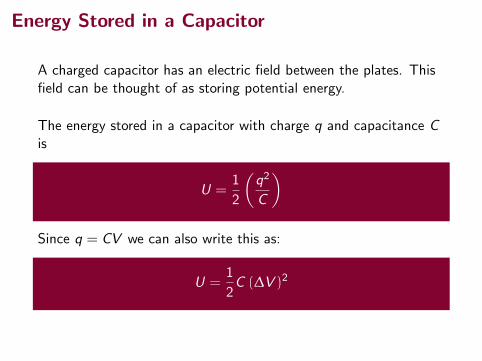
Energy Stored in a Capacitor
A charged capacitor has an electric field between the plates. Thisfield can be thought of as storing potential energy.
The energy stored in a capacitor with charge q and capacitance Cis
U =1
2
(q2
C
)
Since q = CV we can also write this as:
U =1
2C (∆V )2
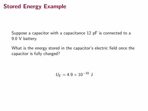
Stored Energy Example
Suppose a capacitor with a capacitance 12 pF is connected to a9.0 V battery.
What is the energy stored in the capacitor’s electric field once thecapacitor is fully charged?
UE = 4.9× 10⁻¹⁰ J
Stored Energy Example
Suppose a capacitor with a capacitance 12 pF is connected to a9.0 V battery.
What is the energy stored in the capacitor’s electric field once thecapacitor is fully charged?
UE = 4.9× 10⁻¹⁰ J
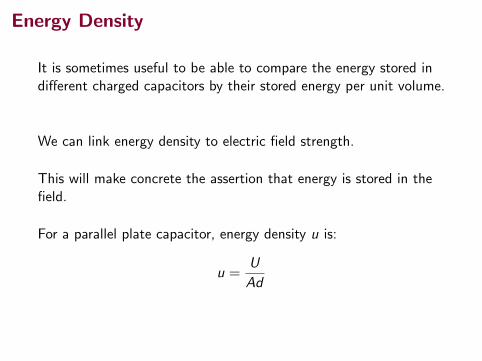
Energy Density
It is sometimes useful to be able to compare the energy stored indifferent charged capacitors by their stored energy per unit volume.
We can link energy density to electric field strength.
This will make concrete the assertion that energy is stored in thefield.
For a parallel plate capacitor, energy density u is:
u =U
Ad
(Ad is the volume between the capacitor plates.)
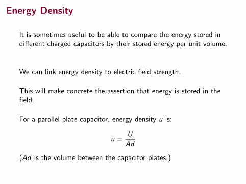
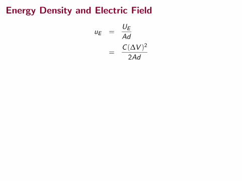
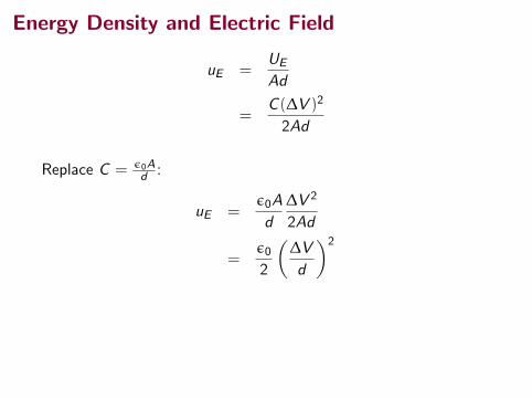
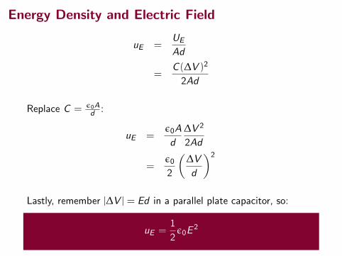
Energy Density and Electric Field
uE =UE
Ad
=C (∆V )2
2Ad
Replace C = ε0Ad :
uE =ε0A
d
∆V 2
2Ad
=ε0
2
(∆V
d
)2
Lastly, remember |∆V | = Ed in a parallel plate capacitor, so:
uE =1
2ε0E
2
Energy Density and Electric Field
uE =UE
Ad
=C (∆V )2
2Ad
Replace C = ε0Ad :
uE =ε0A
d
∆V 2
2Ad
=ε0
2
(∆V
d
)2
Lastly, remember |∆V | = Ed in a parallel plate capacitor, so:
uE =1
2ε0E
2
Energy Density and Electric Field
uE =UE
Ad
=C (∆V )2
2Ad
Replace C = ε0Ad :
uE =ε0A
d
∆V 2
2Ad
=ε0
2
(∆V
d
)2
Lastly, remember |∆V | = Ed in a parallel plate capacitor, so:
uE =1
2ε0E
2

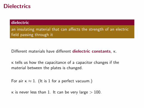
Dielectrics
dielectric
an insulating material that can affects the strength of an electricfield passing through it
Different materials have different dielectric constants, κ.
κ tells us how the capacitance of a capacitor changes if thematerial between the plates is changed.
For air κ ≈ 1. (It is 1 for a perfect vacuum.)
κ is never less than 1. It can be very large > 100.
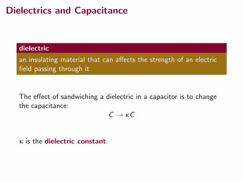
Dielectrics and Capacitance
dielectric
an insulating material that can affects the strength of an electricfield passing through it
The effect of sandwiching a dielectric in a capacitor is to changethe capacitance:
C → κC
κ is the dielectric constant.

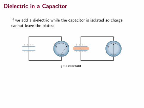
Dielectric in a Capacitor
Capacitance C
670 CHAPTE R 25 CAPACITANCE
HALLIDAY REVISED
increase the capacitance of a capacitor, and some materials, such as strontium ti-tanate, can increase the capacitance by more than two orders of magnitude.
Another effect of the introduction of a dielectric is to limit the potentialdifference that can be applied between the plates to a certain value Vmax, calledthe breakdown potential. If this value is substantially exceeded, the dielectricmaterial will break down and form a conducting path between the plates. Everydielectric material has a characteristic dielectric strength, which is the maximumvalue of the electric field that it can tolerate without breakdown. A few suchvalues are listed in Table 25-1.
As we discussed just after Eq. 25-18, the capacitance of any capacitor can bewritten in the form C ! "0!, (25-26)
in which ! has the dimension of length. For example, ! ! A /d for a parallel-platecapacitor. Faraday’s discovery was that, with a dielectric completely filling thespace between the plates, Eq. 25-26 becomes
C ! k"0! ! kCair, (25-27)where Cair is the value of the capacitance with only air between the plates. For ex-ample, if we fill a capacitor with strontium titanate, with a dielectric constant of310, we multiply the capacitance by 310.
Figure 25-13 provides some insight into Faraday’s experiments. In Fig. 25-13a the battery ensures that the potential difference V between the plateswill remain constant. When a dielectric slab is inserted between the plates, thecharge q on the plates increases by a factor of k; the additional charge is deliveredto the capacitor plates by the battery. In Fig. 25-13b there is no battery, and there-fore the charge q must remain constant when the dielectric slab is inserted; thenthe potential difference V between the plates decreases by a factor of k.Both these observations are consistent (through the relation q ! CV) with theincrease in capacitance caused by the dielectric.
Comparison of Eqs. 25-26 and 25-27 suggests that the effect of a dielectriccan be summed up in more general terms:
In a region completely filled by a dielectric material of dielectric constant k, all electrostatic equations containing the permittivity constant "0 are to be modified by replacing "0 with k"0.
Thus, the magnitude of the electric field produced by a point charge inside adielectric is given by this modified form of Eq. 23-15:
(25-28)
Also, the expression for the electric field just outside an isolated conductorimmersed in a dielectric (see Eq. 23-11) becomes
(25-29)
Because k is always greater than unity, both these equations show that for a fixeddistribution of charges, the effect of a dielectric is to weaken the electric field thatwould otherwise be present.
E !#
$"0.
E !1
4%$"0
qr 2 .
Fig. 25-13 (a) If the potential differencebetween the plates of a capacitor is main-tained, as by battery B, the effect of a dielec-tric is to increase the charge on the plates.(b) If the charge on the capacitor plates ismaintained, as in this case, the effect of a dielectric is to reduce the potential differ-ence between the plates.The scale shown isthat of a potentiometer, a device used to measure potential difference (here, betweenthe plates).A capacitor cannot dischargethrough a potentiometer.
(a)
B B
++++++++κ
V = a constant
(b)
q = a constant
+ ++ +
–––– ––––––––
+ ++ +
––––
+
–
+ ++ +
––––
+
–κ0
VOLTS
0
VOLTS
halliday_c25_656-681v2.qxd 23-11-2009 14:32 Page 670
Capacitance κC
670 CHAPTE R 25 CAPACITANCE
HALLIDAY REVISED
increase the capacitance of a capacitor, and some materials, such as strontium ti-tanate, can increase the capacitance by more than two orders of magnitude.
Another effect of the introduction of a dielectric is to limit the potentialdifference that can be applied between the plates to a certain value Vmax, calledthe breakdown potential. If this value is substantially exceeded, the dielectricmaterial will break down and form a conducting path between the plates. Everydielectric material has a characteristic dielectric strength, which is the maximumvalue of the electric field that it can tolerate without breakdown. A few suchvalues are listed in Table 25-1.
As we discussed just after Eq. 25-18, the capacitance of any capacitor can bewritten in the form C ! "0!, (25-26)
in which ! has the dimension of length. For example, ! ! A /d for a parallel-platecapacitor. Faraday’s discovery was that, with a dielectric completely filling thespace between the plates, Eq. 25-26 becomes
C ! k"0! ! kCair, (25-27)where Cair is the value of the capacitance with only air between the plates. For ex-ample, if we fill a capacitor with strontium titanate, with a dielectric constant of310, we multiply the capacitance by 310.
Figure 25-13 provides some insight into Faraday’s experiments. In Fig. 25-13a the battery ensures that the potential difference V between the plateswill remain constant. When a dielectric slab is inserted between the plates, thecharge q on the plates increases by a factor of k; the additional charge is deliveredto the capacitor plates by the battery. In Fig. 25-13b there is no battery, and there-fore the charge q must remain constant when the dielectric slab is inserted; thenthe potential difference V between the plates decreases by a factor of k.Both these observations are consistent (through the relation q ! CV) with theincrease in capacitance caused by the dielectric.
Comparison of Eqs. 25-26 and 25-27 suggests that the effect of a dielectriccan be summed up in more general terms:
In a region completely filled by a dielectric material of dielectric constant k, all electrostatic equations containing the permittivity constant "0 are to be modified by replacing "0 with k"0.
Thus, the magnitude of the electric field produced by a point charge inside adielectric is given by this modified form of Eq. 23-15:
(25-28)
Also, the expression for the electric field just outside an isolated conductorimmersed in a dielectric (see Eq. 23-11) becomes
(25-29)
Because k is always greater than unity, both these equations show that for a fixeddistribution of charges, the effect of a dielectric is to weaken the electric field thatwould otherwise be present.
E !#
$"0.
E !1
4%$"0
qr 2 .
Fig. 25-13 (a) If the potential differencebetween the plates of a capacitor is main-tained, as by battery B, the effect of a dielec-tric is to increase the charge on the plates.(b) If the charge on the capacitor plates ismaintained, as in this case, the effect of a dielectric is to reduce the potential differ-ence between the plates.The scale shown isthat of a potentiometer, a device used to measure potential difference (here, betweenthe plates).A capacitor cannot dischargethrough a potentiometer.
(a)
B B
++++++++κ
V = a constant
(b)
q = a constant
+ ++ +
–––– ––––––––
+ ++ +
––––
+
–
+ ++ +
––––
+
–κ0
VOLTS
0
VOLTS
halliday_c25_656-681v2.qxd 23-11-2009 14:32 Page 670
Adding a dielectric increases the capacitance.
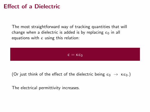
Effect of a Dielectric
The most straightforward way of tracking quantities that willchange when a dielectric is added is by replacing ε0 in allequations with ε using this relation:
ε = κε0
(Or just think of the effect of the dielectric being ε0 → κε0.)
The electrical permittivity increases.
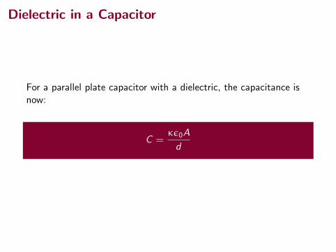
Dielectric in a Capacitor
For a parallel plate capacitor with a dielectric, the capacitance isnow:
C =κε0A
d
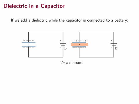
Dielectric in a Capacitor
If we add a dielectric while the capacitor is connected to a battery:670 CHAPTE R 25 CAPACITANCE
HALLIDAY REVISED
increase the capacitance of a capacitor, and some materials, such as strontium ti-tanate, can increase the capacitance by more than two orders of magnitude.
Another effect of the introduction of a dielectric is to limit the potentialdifference that can be applied between the plates to a certain value Vmax, calledthe breakdown potential. If this value is substantially exceeded, the dielectricmaterial will break down and form a conducting path between the plates. Everydielectric material has a characteristic dielectric strength, which is the maximumvalue of the electric field that it can tolerate without breakdown. A few suchvalues are listed in Table 25-1.
As we discussed just after Eq. 25-18, the capacitance of any capacitor can bewritten in the form C ! "0!, (25-26)
in which ! has the dimension of length. For example, ! ! A /d for a parallel-platecapacitor. Faraday’s discovery was that, with a dielectric completely filling thespace between the plates, Eq. 25-26 becomes
C ! k"0! ! kCair, (25-27)where Cair is the value of the capacitance with only air between the plates. For ex-ample, if we fill a capacitor with strontium titanate, with a dielectric constant of310, we multiply the capacitance by 310.
Figure 25-13 provides some insight into Faraday’s experiments. In Fig. 25-13a the battery ensures that the potential difference V between the plateswill remain constant. When a dielectric slab is inserted between the plates, thecharge q on the plates increases by a factor of k; the additional charge is deliveredto the capacitor plates by the battery. In Fig. 25-13b there is no battery, and there-fore the charge q must remain constant when the dielectric slab is inserted; thenthe potential difference V between the plates decreases by a factor of k.Both these observations are consistent (through the relation q ! CV) with theincrease in capacitance caused by the dielectric.
Comparison of Eqs. 25-26 and 25-27 suggests that the effect of a dielectriccan be summed up in more general terms:
In a region completely filled by a dielectric material of dielectric constant k, all electrostatic equations containing the permittivity constant "0 are to be modified by replacing "0 with k"0.
Thus, the magnitude of the electric field produced by a point charge inside adielectric is given by this modified form of Eq. 23-15:
(25-28)
Also, the expression for the electric field just outside an isolated conductorimmersed in a dielectric (see Eq. 23-11) becomes
(25-29)
Because k is always greater than unity, both these equations show that for a fixeddistribution of charges, the effect of a dielectric is to weaken the electric field thatwould otherwise be present.
E !#
$"0.
E !1
4%$"0
qr 2 .
Fig. 25-13 (a) If the potential differencebetween the plates of a capacitor is main-tained, as by battery B, the effect of a dielec-tric is to increase the charge on the plates.(b) If the charge on the capacitor plates ismaintained, as in this case, the effect of a dielectric is to reduce the potential differ-ence between the plates.The scale shown isthat of a potentiometer, a device used to measure potential difference (here, betweenthe plates).A capacitor cannot dischargethrough a potentiometer.
(a)
B B
++++++++κ
V = a constant
(b)
q = a constant
+ ++ +
–––– ––––––––
+ ++ +
––––
+
–
+ ++ +
––––
+
–κ0
VOLTS
0
VOLTS
halliday_c25_656-681v2.qxd 23-11-2009 14:32 Page 670
• q will increase. (q = CV )
• U will increase. (U = 12CV
2)
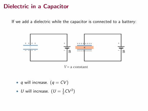
Dielectric in a Capacitor
If we add a dielectric while the capacitor is isolated so chargecannot leave the plates:670 CHAPTE R 25 CAPACITANCE
HALLIDAY REVISED
increase the capacitance of a capacitor, and some materials, such as strontium ti-tanate, can increase the capacitance by more than two orders of magnitude.
Another effect of the introduction of a dielectric is to limit the potentialdifference that can be applied between the plates to a certain value Vmax, calledthe breakdown potential. If this value is substantially exceeded, the dielectricmaterial will break down and form a conducting path between the plates. Everydielectric material has a characteristic dielectric strength, which is the maximumvalue of the electric field that it can tolerate without breakdown. A few suchvalues are listed in Table 25-1.
As we discussed just after Eq. 25-18, the capacitance of any capacitor can bewritten in the form C ! "0!, (25-26)
in which ! has the dimension of length. For example, ! ! A /d for a parallel-platecapacitor. Faraday’s discovery was that, with a dielectric completely filling thespace between the plates, Eq. 25-26 becomes
C ! k"0! ! kCair, (25-27)where Cair is the value of the capacitance with only air between the plates. For ex-ample, if we fill a capacitor with strontium titanate, with a dielectric constant of310, we multiply the capacitance by 310.
Figure 25-13 provides some insight into Faraday’s experiments. In Fig. 25-13a the battery ensures that the potential difference V between the plateswill remain constant. When a dielectric slab is inserted between the plates, thecharge q on the plates increases by a factor of k; the additional charge is deliveredto the capacitor plates by the battery. In Fig. 25-13b there is no battery, and there-fore the charge q must remain constant when the dielectric slab is inserted; thenthe potential difference V between the plates decreases by a factor of k.Both these observations are consistent (through the relation q ! CV) with theincrease in capacitance caused by the dielectric.
Comparison of Eqs. 25-26 and 25-27 suggests that the effect of a dielectriccan be summed up in more general terms:
In a region completely filled by a dielectric material of dielectric constant k, all electrostatic equations containing the permittivity constant "0 are to be modified by replacing "0 with k"0.
Thus, the magnitude of the electric field produced by a point charge inside adielectric is given by this modified form of Eq. 23-15:
(25-28)
Also, the expression for the electric field just outside an isolated conductorimmersed in a dielectric (see Eq. 23-11) becomes
(25-29)
Because k is always greater than unity, both these equations show that for a fixeddistribution of charges, the effect of a dielectric is to weaken the electric field thatwould otherwise be present.
E !#
$"0.
E !1
4%$"0
qr 2 .
Fig. 25-13 (a) If the potential differencebetween the plates of a capacitor is main-tained, as by battery B, the effect of a dielec-tric is to increase the charge on the plates.(b) If the charge on the capacitor plates ismaintained, as in this case, the effect of a dielectric is to reduce the potential differ-ence between the plates.The scale shown isthat of a potentiometer, a device used to measure potential difference (here, betweenthe plates).A capacitor cannot dischargethrough a potentiometer.
(a)
B B
++++++++κ
V = a constant
(b)
q = a constant
+ ++ +
–––– ––––––––
+ ++ +
––––
+
–
+ ++ +
––––
+
–κ0
VOLTS
0
VOLTS
halliday_c25_656-681v2.qxd 23-11-2009 14:32 Page 670
• V will decrease. (V = qC )
• U will decrease. (U = q2
2C )
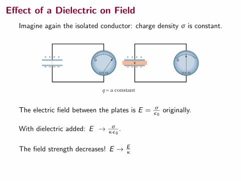
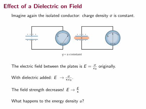
Effect of a Dielectric on Field
Imagine again the isolated conductor: charge density σ is constant.670 CHAPTE R 25 CAPACITANCE
HALLIDAY REVISED
increase the capacitance of a capacitor, and some materials, such as strontium ti-tanate, can increase the capacitance by more than two orders of magnitude.
Another effect of the introduction of a dielectric is to limit the potentialdifference that can be applied between the plates to a certain value Vmax, calledthe breakdown potential. If this value is substantially exceeded, the dielectricmaterial will break down and form a conducting path between the plates. Everydielectric material has a characteristic dielectric strength, which is the maximumvalue of the electric field that it can tolerate without breakdown. A few suchvalues are listed in Table 25-1.
As we discussed just after Eq. 25-18, the capacitance of any capacitor can bewritten in the form C ! "0!, (25-26)
in which ! has the dimension of length. For example, ! ! A /d for a parallel-platecapacitor. Faraday’s discovery was that, with a dielectric completely filling thespace between the plates, Eq. 25-26 becomes
C ! k"0! ! kCair, (25-27)where Cair is the value of the capacitance with only air between the plates. For ex-ample, if we fill a capacitor with strontium titanate, with a dielectric constant of310, we multiply the capacitance by 310.
Figure 25-13 provides some insight into Faraday’s experiments. In Fig. 25-13a the battery ensures that the potential difference V between the plateswill remain constant. When a dielectric slab is inserted between the plates, thecharge q on the plates increases by a factor of k; the additional charge is deliveredto the capacitor plates by the battery. In Fig. 25-13b there is no battery, and there-fore the charge q must remain constant when the dielectric slab is inserted; thenthe potential difference V between the plates decreases by a factor of k.Both these observations are consistent (through the relation q ! CV) with theincrease in capacitance caused by the dielectric.
Comparison of Eqs. 25-26 and 25-27 suggests that the effect of a dielectriccan be summed up in more general terms:
In a region completely filled by a dielectric material of dielectric constant k, all electrostatic equations containing the permittivity constant "0 are to be modified by replacing "0 with k"0.
Thus, the magnitude of the electric field produced by a point charge inside adielectric is given by this modified form of Eq. 23-15:
(25-28)
Also, the expression for the electric field just outside an isolated conductorimmersed in a dielectric (see Eq. 23-11) becomes
(25-29)
Because k is always greater than unity, both these equations show that for a fixeddistribution of charges, the effect of a dielectric is to weaken the electric field thatwould otherwise be present.
E !#
$"0.
E !1
4%$"0
qr 2 .
Fig. 25-13 (a) If the potential differencebetween the plates of a capacitor is main-tained, as by battery B, the effect of a dielec-tric is to increase the charge on the plates.(b) If the charge on the capacitor plates ismaintained, as in this case, the effect of a dielectric is to reduce the potential differ-ence between the plates.The scale shown isthat of a potentiometer, a device used to measure potential difference (here, betweenthe plates).A capacitor cannot dischargethrough a potentiometer.
(a)
B B
++++++++κ
V = a constant
(b)
q = a constant
+ ++ +
–––– ––––––––
+ ++ +
––––
+
–
+ ++ +
––––
+
–κ0
VOLTS
0
VOLTS
halliday_c25_656-681v2.qxd 23-11-2009 14:32 Page 670
The electric field between the plates is E = σε0
originally.
With dielectric added: E → σκε0
.
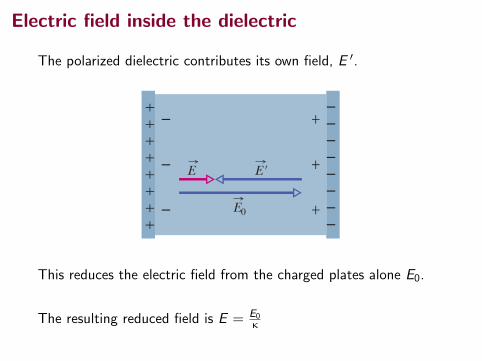
The field strength decreases! E → Eκ
What happens to the energy density u?
Effect of a Dielectric on Field
Imagine again the isolated conductor: charge density σ is constant.670 CHAPTE R 25 CAPACITANCE
HALLIDAY REVISED
increase the capacitance of a capacitor, and some materials, such as strontium ti-tanate, can increase the capacitance by more than two orders of magnitude.
Another effect of the introduction of a dielectric is to limit the potentialdifference that can be applied between the plates to a certain value Vmax, calledthe breakdown potential. If this value is substantially exceeded, the dielectricmaterial will break down and form a conducting path between the plates. Everydielectric material has a characteristic dielectric strength, which is the maximumvalue of the electric field that it can tolerate without breakdown. A few suchvalues are listed in Table 25-1.
As we discussed just after Eq. 25-18, the capacitance of any capacitor can bewritten in the form C ! "0!, (25-26)
in which ! has the dimension of length. For example, ! ! A /d for a parallel-platecapacitor. Faraday’s discovery was that, with a dielectric completely filling thespace between the plates, Eq. 25-26 becomes
C ! k"0! ! kCair, (25-27)where Cair is the value of the capacitance with only air between the plates. For ex-ample, if we fill a capacitor with strontium titanate, with a dielectric constant of310, we multiply the capacitance by 310.
Figure 25-13 provides some insight into Faraday’s experiments. In Fig. 25-13a the battery ensures that the potential difference V between the plateswill remain constant. When a dielectric slab is inserted between the plates, thecharge q on the plates increases by a factor of k; the additional charge is deliveredto the capacitor plates by the battery. In Fig. 25-13b there is no battery, and there-fore the charge q must remain constant when the dielectric slab is inserted; thenthe potential difference V between the plates decreases by a factor of k.Both these observations are consistent (through the relation q ! CV) with theincrease in capacitance caused by the dielectric.
Comparison of Eqs. 25-26 and 25-27 suggests that the effect of a dielectriccan be summed up in more general terms:
In a region completely filled by a dielectric material of dielectric constant k, all electrostatic equations containing the permittivity constant "0 are to be modified by replacing "0 with k"0.
Thus, the magnitude of the electric field produced by a point charge inside adielectric is given by this modified form of Eq. 23-15:
(25-28)
Also, the expression for the electric field just outside an isolated conductorimmersed in a dielectric (see Eq. 23-11) becomes
(25-29)
Because k is always greater than unity, both these equations show that for a fixeddistribution of charges, the effect of a dielectric is to weaken the electric field thatwould otherwise be present.
E !#
$"0.
E !1
4%$"0
qr 2 .
Fig. 25-13 (a) If the potential differencebetween the plates of a capacitor is main-tained, as by battery B, the effect of a dielec-tric is to increase the charge on the plates.(b) If the charge on the capacitor plates ismaintained, as in this case, the effect of a dielectric is to reduce the potential differ-ence between the plates.The scale shown isthat of a potentiometer, a device used to measure potential difference (here, betweenthe plates).A capacitor cannot dischargethrough a potentiometer.
(a)
B B
++++++++κ
V = a constant
(b)
q = a constant
+ ++ +
–––– ––––––––
+ ++ +
––––
+
–
+ ++ +
––––
+
–κ0
VOLTS
0
VOLTS
halliday_c25_656-681v2.qxd 23-11-2009 14:32 Page 670
The electric field between the plates is E = σε0
originally.
With dielectric added: E → σκε0
.
The field strength decreases! E → Eκ
What happens to the energy density u?
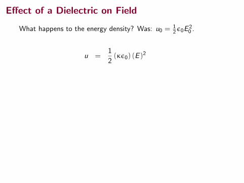
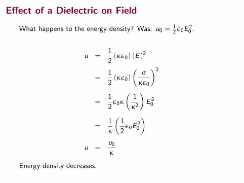
Effect of a Dielectric on Field
What happens to the energy density? Was: u0 =12ε0E
20 .
u =1
2(κε0) (E )
2
=1
2(κε0)
(σ
κε0
)2
=1
2ε0κ
(1
κ2
)E 20
=1
κ
(1
2ε0E
20
)u =
u0κ
Energy density decreases.
Effect of a Dielectric on Field
What happens to the energy density? Was: u0 =12ε0E
20 .
u =1
2(κε0) (E )
2
=1
2(κε0)
(σ
κε0
)2
=1
2ε0κ
(1
κ2
)E 20
=1
κ
(1
2ε0E
20
)u =
u0κ
Energy density decreases.

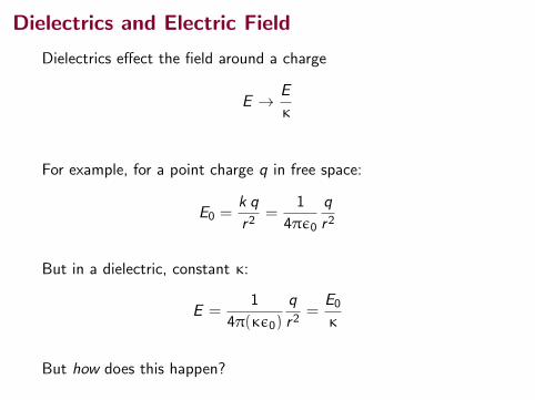
Dielectrics and Electric Field
Dielectrics effect the field around a charge
E → E
κ
For example, for a point charge q in free space:
E0 =k q
r2=
1
4πε0
q
r2
But in a dielectric, constant κ:
E =1
4π(κε0)
q
r2=
E0
κ
But how does this happen?
Dielectrics and Electric Field
Dielectrics effect the field around a charge
E → E
κ
For example, for a point charge q in free space:
E0 =k q
r2=
1
4πε0
q
r2
But in a dielectric, constant κ:
E =1
4π(κε0)
q
r2=
E0
κ
But how does this happen?
Dielectrics and Electric Field
Dielectrics become polarized by the presence of an electric field.
There are two types of dielectrics, the process is a little different ineach:
• polar dielectrics
• nonpolar dielectrics
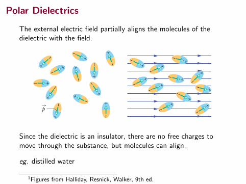
Polar Dielectrics
The external electric field partially aligns the molecules of thedielectric with the field.
67125-7 DI E LECTR ICS: AN ATOM IC VI EWPART 3
HALLIDAY REVISED
25-7 Dielectrics: An Atomic ViewWhat happens, in atomic and molecular terms, when we put a dielectric in anelectric field? There are two possibilities, depending on the type of molecule:
1. Polar dielectrics. The molecules of some dielectrics, like water, have permanentelectric dipole moments. In such materials (called polar dielectrics), the electricdipoles tend to line up with an external electric field as in Fig. 25-14. Because themolecules are continuously jostling each other as a result of their random thermalmotion, this alignment is not complete, but it becomes more complete as the mag-nitude of the applied field is increased (or as the temperature, and thus thejostling, are decreased).The alignment of the electric dipoles produces an electricfield that is directed opposite the applied field and is smaller in magnitude.
Sample Problem
Because the battery has been disconnected, the charge onthe capacitor cannot change when the dielectric is inserted.However, the potential does change.
Calculations: Thus, we must now use Eq. 25-21 to write thefinal potential energy Uf , but now that the slab is within thecapacitor, the capacitance is kC.We then have
(Answer)When the slab is introduced, the potential energy decreasesby a factor of k.
The “missing” energy, in principle, would be apparent tothe person who introduced the slab.The capacitor would ex-ert a tiny tug on the slab and would do work on it, in amount
W ! Ui " Uf ! (1055 " 162) pJ ! 893 pJ.
If the slab were allowed to slide between the plates with norestraint and if there were no friction, the slab would oscillateback and forth between the plates with a (constant) mechani-cal energy of 893 pJ, and this system energy would transferback and forth between kinetic energy of the moving slab andpotential energy stored in the electric field.
! 162 pJ ! 160 pJ.
Uf !q2
2#C!
Ui
#!
1055 pJ6.50
Additional examples, video, and practice available at WileyPLUS
Work and energy when a dielectric is inserted into a capacitor
A parallel-plate capacitor whose capacitance C is 13.5 pF ischarged by a battery to a potential difference V ! 12.5 Vbetween its plates. The charging battery is now discon-nected, and a porcelain slab (k ! 6.50) is slipped betweenthe plates.
(a) What is the potential energy of the capacitor before theslab is inserted?
We can relate the potential energy Ui of the capacitor to thecapacitance C and either the potential V (with Eq. 25-22) orthe charge q (with Eq. 25-21):
Calculation: Because we are given the initial potentialV (! 12.5 V), we use Eq. 25-22 to find the initial storedenergy:
(Answer)
(b) What is the potential energy of the capacitor–slab deviceafter the slab is inserted?
! 1.055 $ 10"9 J ! 1055 pJ ! 1100 pJ.Ui ! 1
2CV 2 ! 12(13.5 $ 10"12 F)(12.5 V)2
Ui ! 12CV2 !
q2
2C.
KEY I DEA
KEY I DEA
Fig. 25-14 (a) Moleculeswith a permanent electric dipolemoment, showing their randomorientation in the absence of anexternal electric field. (b) Anelectric field is applied, produc-ing partial alignment of thedipoles.Thermal agitation pre-vents complete alignment.
+–
+–
+–
+–
+–
+–
+–
+–
+–
+–
+–
+ –
+ –
+ –
+ –
+ –
+ –
+ – + –
+
–
+ –
+ – +
–
(a) (b)
p
halliday_c25_656-681v2.qxd 23-11-2009 16:32 Page 671
Since the dielectric is an insulator, there are no free charges tomove through the substance, but molecules can align.
eg. distilled water
1Figures from Halliday, Resnick, Walker, 9th ed.
Nonpolar Dielectrics
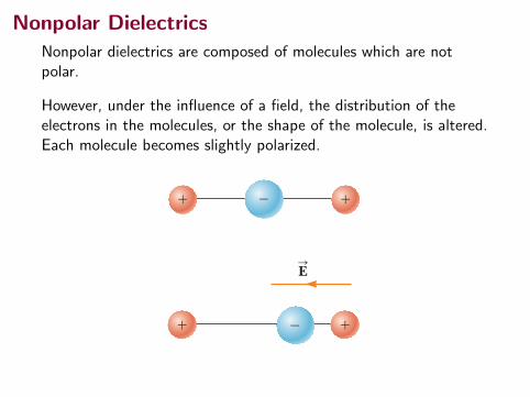
Nonpolar dielectrics are composed of molecules which are notpolar.
However, under the influence of a field, the distribution of theelectrons in the molecules, or the shape of the molecule, is altered.Each molecule becomes slightly polarized.
!"
" "
"
!
ES
a
b
Nonpolar Dielectrics
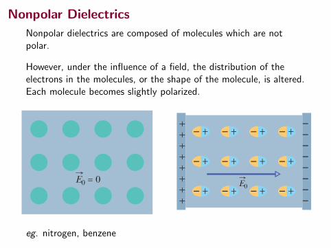
Nonpolar dielectrics are composed of molecules which are notpolar.
However, under the influence of a field, the distribution of theelectrons in the molecules, or the shape of the molecule, is altered.Each molecule becomes slightly polarized.
672 CHAPTE R 25 CAPACITANCE
HALLIDAY REVISED
2. Nonpolar dielectrics. Regardless of whether they have permanent electricdipole moments, molecules acquire dipole moments by induction when placed in an external electric field. In Section 24-8 (see Fig. 24-11), we saw that this occurs because the external field tends to “stretch” the molecules,slightly separating the centers of negative and positive charge.
Figure 25-15a shows a nonpolar dielectric slab with no external electric fieldapplied. In Fig. 25-15b, an electric field is applied via a capacitor, whose platesare charged as shown. The result is a slight separation of the centers of the posi-tive and negative charge distributions within the slab, producing positive chargeon one face of the slab (due to the positive ends of dipoles there) and negativecharge on the opposite face (due to the negative ends of dipoles there). The slabas a whole remains electrically neutral and—within the slab—there is no excesscharge in any volume element.
Figure 25-15c shows that the induced surface charges on the faces produce anelectric field in the direction opposite that of the applied electric field . Theresultant field inside the dielectric (the vector sum of fields and ) has thedirection of but is smaller in magnitude.
Both the field produced by the surface charges in Fig. 25-15c and the electricfield produced by the permanent electric dipoles in Fig. 25-14 act in the same way—they oppose the applied field .Thus, the effect of both polar and nonpolar dielectricsis to weaken any applied field within them,as between the plates of a capacitor.
25-8 Dielectrics and Gauss’ LawIn our discussion of Gauss’ law in Chapter 23, we assumed that the chargesexisted in a vacuum. Here we shall see how to modify and generalize that law ifdielectric materials, such as those listed in Table 25-1, are present. Figure 25-16shows a parallel-plate capacitor of plate area A, both with and without a dielectric. We assume that the charge q on the plates is the same in both situa-tions. Note that the field between the plates induces charges on the faces of thedielectric by one of the methods described in Section 25-7.
For the situation of Fig. 25-16a, without a dielectric, we can find the electricfield between the plates as we did in Fig. 25-5:We enclose the charge !q on thetop plate with a Gaussian surface and then apply Gauss’ law. Letting E0 representthe magnitude of the field, we find
(25-30)
or (25-31)
In Fig. 25-16b, with the dielectric in place, we can find the electric fieldbetween the plates (and within the dielectric) by using the same Gaussian sur-face. However, now the surface encloses two types of charge: It still encloses
E0 "q
#0A.
#0 ! E:
! dA:
" #0EA " q,
E:
0
E:
E:
$E:
0
E:
$E:
0E:
E:
0E:
$
E:
0
Fig. 25-15 (a) A nonpolar dielectricslab.The circles represent the electricallyneutral atoms within the slab. (b) An elec-tric field is applied via charged capacitorplates; the field slightly stretches the atoms,separating the centers of positive and nega-tive charge. (c) The separation producessurface charges on the slab faces.Thesecharges set up a field which opposes theapplied field .The resultant field insidethe dielectric (the vector sum of and )has the same direction as but a smallermagnitude.
E:
0
E:
$E:
0
E:
E:
0
E:
$,
(a)
E0 = 0
The initial electric fieldinside this nonpolardielectric slab is zero.
+–
+–
+–
+–
+–
+–
+–
+–
+–
+–
+–
+–E0
(b)
++
++
++
++
–––––––
–
The applied fieldaligns the atomicdipole moments.
+–
+–
+–
E'
E0
(c)
++
++
++
++
–––––––
–
E
The field of the alignedatoms is opposite theapplied field.
Fig. 25-16A parallel-platecapacitor (a) with-out and (b) with a di-electric slab inserted.The charge q on theplates is assumed tobe the same in bothcases. (b)
–q'
+q'
+ + + + + + + ++ +
– – – – – – – –– –+ + + ++
– – – ––
κ
+q
–q
Gaussian surface
EE0
Gaussian surface
+q
–q
(a)
+ + + + + + + ++ +
– – – – – – – –– –
halliday_c25_656-681v2.qxd 23-11-2009 14:32 Page 672
eg. nitrogen, benzene
Electric field inside the dielectric
The polarized dielectric contributes its own field, E ′.
672 CHAPTE R 25 CAPACITANCE
HALLIDAY REVISED
2. Nonpolar dielectrics. Regardless of whether they have permanent electricdipole moments, molecules acquire dipole moments by induction when placed in an external electric field. In Section 24-8 (see Fig. 24-11), we saw that this occurs because the external field tends to “stretch” the molecules,slightly separating the centers of negative and positive charge.
Figure 25-15a shows a nonpolar dielectric slab with no external electric fieldapplied. In Fig. 25-15b, an electric field is applied via a capacitor, whose platesare charged as shown. The result is a slight separation of the centers of the posi-tive and negative charge distributions within the slab, producing positive chargeon one face of the slab (due to the positive ends of dipoles there) and negativecharge on the opposite face (due to the negative ends of dipoles there). The slabas a whole remains electrically neutral and—within the slab—there is no excesscharge in any volume element.
Figure 25-15c shows that the induced surface charges on the faces produce anelectric field in the direction opposite that of the applied electric field . Theresultant field inside the dielectric (the vector sum of fields and ) has thedirection of but is smaller in magnitude.
Both the field produced by the surface charges in Fig. 25-15c and the electricfield produced by the permanent electric dipoles in Fig. 25-14 act in the same way—they oppose the applied field .Thus, the effect of both polar and nonpolar dielectricsis to weaken any applied field within them,as between the plates of a capacitor.
25-8 Dielectrics and Gauss’ LawIn our discussion of Gauss’ law in Chapter 23, we assumed that the chargesexisted in a vacuum. Here we shall see how to modify and generalize that law ifdielectric materials, such as those listed in Table 25-1, are present. Figure 25-16shows a parallel-plate capacitor of plate area A, both with and without a dielectric. We assume that the charge q on the plates is the same in both situa-tions. Note that the field between the plates induces charges on the faces of thedielectric by one of the methods described in Section 25-7.
For the situation of Fig. 25-16a, without a dielectric, we can find the electricfield between the plates as we did in Fig. 25-5:We enclose the charge !q on thetop plate with a Gaussian surface and then apply Gauss’ law. Letting E0 representthe magnitude of the field, we find
(25-30)
or (25-31)
In Fig. 25-16b, with the dielectric in place, we can find the electric fieldbetween the plates (and within the dielectric) by using the same Gaussian sur-face. However, now the surface encloses two types of charge: It still encloses
E0 "q
#0A.
#0 ! E:
! dA:
" #0EA " q,
E:
0
E:
E:
$E:
0
E:
$E:
0E:
E:
0E:
$
E:
0
Fig. 25-15 (a) A nonpolar dielectricslab.The circles represent the electricallyneutral atoms within the slab. (b) An elec-tric field is applied via charged capacitorplates; the field slightly stretches the atoms,separating the centers of positive and nega-tive charge. (c) The separation producessurface charges on the slab faces.Thesecharges set up a field which opposes theapplied field .The resultant field insidethe dielectric (the vector sum of and )has the same direction as but a smallermagnitude.
E:
0
E:
$E:
0
E:
E:
0
E:
$,
(a)
E0 = 0
The initial electric fieldinside this nonpolardielectric slab is zero.
+–
+–
+–
+–
+–
+–
+–
+–
+–
+–
+–
+–E0
(b)
++
++
++
++
–––––––
–
The applied fieldaligns the atomicdipole moments.
+–
+–
+–
E'
E0
(c)
++
++
++
++
–––––––
–
E
The field of the alignedatoms is opposite theapplied field.
Fig. 25-16A parallel-platecapacitor (a) with-out and (b) with a di-electric slab inserted.The charge q on theplates is assumed tobe the same in bothcases. (b)
–q'
+q'
+ + + + + + + ++ +
– – – – – – – –– –+ + + ++
– – – ––
κ
+q
–q
Gaussian surface
EE0
Gaussian surface
+q
–q
(a)
+ + + + + + + ++ +
– – – – – – – –– –
halliday_c25_656-681v2.qxd 23-11-2009 14:32 Page 672
This reduces the electric field from the charged plates alone E0.
The resulting reduced field is E = E0κ
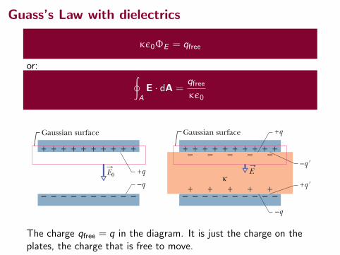
Guass’s Law with dielectrics
κε0ΦE = qfree
or: ∮A
E · dA =qfreeκε0
672 CHAPTE R 25 CAPACITANCE
HALLIDAY REVISED
2. Nonpolar dielectrics. Regardless of whether they have permanent electricdipole moments, molecules acquire dipole moments by induction when placed in an external electric field. In Section 24-8 (see Fig. 24-11), we saw that this occurs because the external field tends to “stretch” the molecules,slightly separating the centers of negative and positive charge.
Figure 25-15a shows a nonpolar dielectric slab with no external electric fieldapplied. In Fig. 25-15b, an electric field is applied via a capacitor, whose platesare charged as shown. The result is a slight separation of the centers of the posi-tive and negative charge distributions within the slab, producing positive chargeon one face of the slab (due to the positive ends of dipoles there) and negativecharge on the opposite face (due to the negative ends of dipoles there). The slabas a whole remains electrically neutral and—within the slab—there is no excesscharge in any volume element.
Figure 25-15c shows that the induced surface charges on the faces produce anelectric field in the direction opposite that of the applied electric field . Theresultant field inside the dielectric (the vector sum of fields and ) has thedirection of but is smaller in magnitude.
Both the field produced by the surface charges in Fig. 25-15c and the electricfield produced by the permanent electric dipoles in Fig. 25-14 act in the same way—they oppose the applied field .Thus, the effect of both polar and nonpolar dielectricsis to weaken any applied field within them,as between the plates of a capacitor.
25-8 Dielectrics and Gauss’ LawIn our discussion of Gauss’ law in Chapter 23, we assumed that the chargesexisted in a vacuum. Here we shall see how to modify and generalize that law ifdielectric materials, such as those listed in Table 25-1, are present. Figure 25-16shows a parallel-plate capacitor of plate area A, both with and without a dielectric. We assume that the charge q on the plates is the same in both situa-tions. Note that the field between the plates induces charges on the faces of thedielectric by one of the methods described in Section 25-7.
For the situation of Fig. 25-16a, without a dielectric, we can find the electricfield between the plates as we did in Fig. 25-5:We enclose the charge !q on thetop plate with a Gaussian surface and then apply Gauss’ law. Letting E0 representthe magnitude of the field, we find
(25-30)
or (25-31)
In Fig. 25-16b, with the dielectric in place, we can find the electric fieldbetween the plates (and within the dielectric) by using the same Gaussian sur-face. However, now the surface encloses two types of charge: It still encloses
E0 "q
#0A.
#0 ! E:
! dA:
" #0EA " q,
E:
0
E:
E:
$E:
0
E:
$E:
0E:
E:
0E:
$
E:
0
Fig. 25-15 (a) A nonpolar dielectricslab.The circles represent the electricallyneutral atoms within the slab. (b) An elec-tric field is applied via charged capacitorplates; the field slightly stretches the atoms,separating the centers of positive and nega-tive charge. (c) The separation producessurface charges on the slab faces.Thesecharges set up a field which opposes theapplied field .The resultant field insidethe dielectric (the vector sum of and )has the same direction as but a smallermagnitude.
E:
0
E:
$E:
0
E:
E:
0
E:
$,
(a)
E0 = 0
The initial electric fieldinside this nonpolardielectric slab is zero.
+–
+–
+–
+–
+–
+–
+–
+–
+–
+–
+–
+–E0
(b)
++
++
++
++
–––––––
–
The applied fieldaligns the atomicdipole moments.
+–
+–
+–
E'
E0
(c)
++
++
++
++
–––––––
–
E
The field of the alignedatoms is opposite theapplied field.
Fig. 25-16A parallel-platecapacitor (a) with-out and (b) with a di-electric slab inserted.The charge q on theplates is assumed tobe the same in bothcases. (b)
–q'
+q'
+ + + + + + + ++ +
– – – – – – – –– –+ + + ++
– – – ––
κ
+q
–q
Gaussian surface
EE0
Gaussian surface
+q
–q
(a)
+ + + + + + + ++ +
– – – – – – – –– –
halliday_c25_656-681v2.qxd 23-11-2009 14:32 Page 672
The charge qfree = q in the diagram. It is just the charge on theplates, the charge that is free to move.
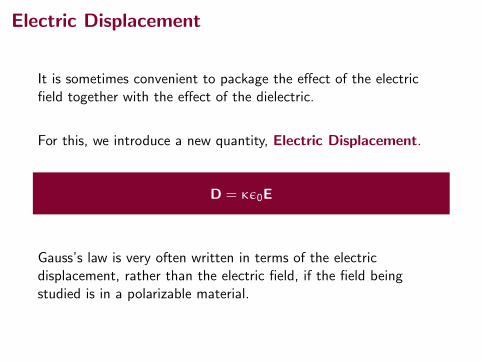
Electric Displacement
It is sometimes convenient to package the effect of the electricfield together with the effect of the dielectric.
For this, we introduce a new quantity, Electric Displacement.
D = κε0E
Gauss’s law is very often written in terms of the electricdisplacement, rather than the electric field, if the field beingstudied is in a polarizable material.
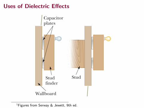
Uses of Dielectric Effects
792 Chapter 26 Capacitance and Dielectrics
Types of CapacitorsMany capacitors are built into integrated circuit chips, but some electrical devices still use stand-alone capacitors. Commercial capacitors are often made from metal-lic foil interlaced with thin sheets of either paraffin-impregnated paper or Mylar as the dielectric material. These alternate layers of metallic foil and dielectric are rolled into a cylinder to form a small package (Fig. 26.14a). High-voltage capacitors commonly consist of a number of interwoven metallic plates immersed in silicone oil (Fig. 26.14b). Small capacitors are often constructed from ceramic materials. Often, an electrolytic capacitor is used to store large amounts of charge at relatively low voltages. This device, shown in Figure 26.14c, consists of a metallic foil in con-tact with an electrolyte, a solution that conducts electricity by virtue of the motion of ions contained in the solution. When a voltage is applied between the foil and the electrolyte, a thin layer of metal oxide (an insulator) is formed on the foil, and this layer serves as the dielectric. Very large values of capacitance can be obtained in an electrolytic capacitor because the dielectric layer is very thin and therefore the plate separation is very small. Electrolytic capacitors are not reversible as are many other capacitors. They have a polarity, which is indicated by positive and negative signs marked on the device. When electrolytic capacitors are used in circuits, the polarity must be cor-rect. If the polarity of the applied voltage is the opposite of what is intended, the oxide layer is removed and the capacitor conducts electricity instead of storing charge. Variable capacitors (typically 10 to 500 pF) usually consist of two interwoven sets of metallic plates, one fixed and the other movable, and contain air as the dielec-tric (Fig. 26.15). These types of capacitors are often used in radio tuning circuits.
Q uick Quiz 26.5 If you have ever tried to hang a picture or a mirror, you know it can be difficult to locate a wooden stud in which to anchor your nail or screw. A carpenter’s stud finder is a capacitor with its plates arranged side by side instead of facing each other as shown in Figure 26.16. When the device is moved over a stud, does the capacitance (a) increase or (b) decrease?
Plates
ElectrolyteCase
Metallic foil ! oxide layer
Contacts
Metal foil
Paper
An electrolytic capacitor
Oil
a b c
A tubular capacitor whose plates are separated by paper and then rolled into a cylinder
A high-voltage capacitor consisting of many parallel plates separated by insulating oil
Figure 26.14 Three commercial capacitor designs.
When one set of metal plates is rotated so as to lie between a fixed set of plates, the capacitance of the device changes.
Figure 26.15 A variable capacitor.
. C
enga
ge L
earn
ing/
Geor
ge S
empl
e
Capacitorplates
Stud finder
Wallboard
Stud
a b
The materials between the plates of the capacitor are the wallboard and air.
When the capacitor moves across a stud in the wall, the materials between the plates are the wallboard and the wood stud. The change in the dielectric constant causes a signal light to illuminate.
Figure 26.16 (Quick Quiz 26.5) A stud finder.
Example 26.5 Energy Stored Before and After
A parallel-plate capacitor is charged with a battery to a charge Q 0. The battery is then removed, and a slab of material that has a dielectric constant k is inserted between the plates. Identify the system as the capacitor and the dielectric. Find the energy stored in the system before and after the dielectric is inserted.
AM
1Figures from Serway & Jewett, 9th ed.
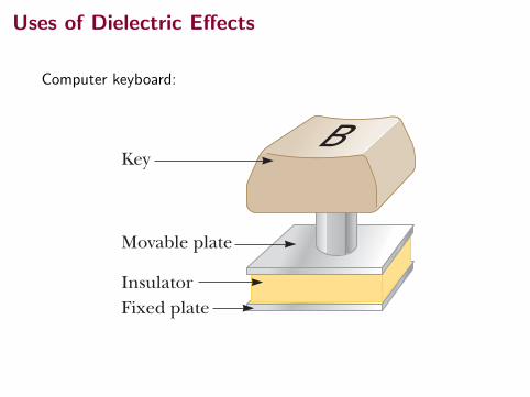
Uses of Dielectric Effects
Computer keyboard:
780 Chapter 26 Capacitance and Dielectrics
Example 26.1 The Cylindrical Capacitor
A solid cylindrical conductor of radius a and charge Q is coaxial with a cylindrical shell of negligible thick-ness, radius b . a, and charge 2Q (Fig. 26.4a). Find the capacitance of this cylindrical capacitor if its length is ,.
Conceptualize Recall that any pair of conductors qualifies as a capacitor, so the system described in this example therefore qualifies. Figure 26.4b helps visual-ize the electric field between the conductors. We expect the capacitance to depend only on geometric factors, which, in this case, are a, b, and ,.
Categorize Because of the cylindrical symmetry of the system, we can use results from previous studies of cylin-drical systems to find the capacitance.
S O L U T I O N
Substituting this result into Equation 26.1, we find that the capacitance is
C 5Q
DV5
QQd/P0A
C 5P0Ad
(26.3)
That is, the capacitance of a parallel-plate capacitor is proportional to the area of its plates and inversely proportional to the plate separation. Let’s consider how the geometry of these conductors influences the capacity of the pair of plates to store charge. As a capacitor is being charged by a battery, elec-trons flow into the negative plate and out of the positive plate. If the capacitor plates are large, the accumulated charges are able to distribute themselves over a substantial area and the amount of charge that can be stored on a plate for a given potential difference increases as the plate area is increased. Therefore, it is reason-able that the capacitance is proportional to the plate area A as in Equation 26.3. Now consider the region that separates the plates. Imagine moving the plates closer together. Consider the situation before any charges have had a chance to move in response to this change. Because no charges have moved, the electric field between the plates has the same value but extends over a shorter distance. There-fore, the magnitude of the potential difference between the plates DV 5 Ed (Eq. 25.6) is smaller. The difference between this new capacitor voltage and the terminal voltage of the battery appears as a potential difference across the wires connecting the battery to the capacitor, resulting in an electric field in the wires that drives more charge onto the plates and increases the potential difference between the plates. When the potential difference between the plates again matches that of the battery, the flow of charge stops. Therefore, moving the plates closer together causes the charge on the capacitor to increase. If d is increased, the charge decreases. As a result, the inverse relationship between C and d in Equation 26.3 is reasonable.
Q uick Quiz 26.2 Many computer keyboard buttons are constructed of capacitors as shown in Figure 26.3. When a key is pushed down, the soft insulator between the movable plate and the fixed plate is compressed. When the key is pressed, what happens to the capacitance? (a) It increases. (b) It decreases. (c) It changes in a way you cannot determine because the electric circuit connected to the key-board button may cause a change in DV.
Capacitance of parallel plates X
KeyB
Movable plate
InsulatorFixed plate
Figure 26.3 (Quick Quiz 26.2) One type of computer keyboard button.
ba
!
Gaussiansurface
!Q
!Q
aQ
Q
b
r
a b
Figure 26.4 (Example 26.1) (a) A cylindrical capacitor consists of a solid cylindrical conductor of radius a and length , sur-rounded by a coaxial cylindrical shell of radius b. (b) End view. The electric field lines are radial. The dashed line represents the end of a cylindrical gaussian surface of radius r and length ,.
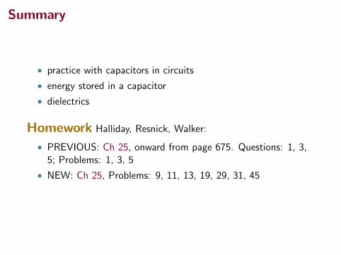
Summary
• practice with capacitors in circuits
• energy stored in a capacitor
• dielectrics
Homework Halliday, Resnick, Walker:
• PREVIOUS: Ch 25, onward from page 675. Questions: 1, 3,5; Problems: 1, 3, 5
• NEW: Ch 25, Problems: 9, 11, 13, 19, 29, 31, 45