Embed Size (px)
Citation preview
Electrical Storage for Low Voltage
Distribution NetworksEnrico Tironi
Dipartimento di Elettronica, Informazione e Bioingegneria
Politecnico di Milano
Sesto Val Pusteria, June 30th 2016

Enrico Tironi [email protected]
ApplicationsPeak Shaving – Time Shift
• Storage can contribute to shift and/or level the electric
energy demand, making it somehow asynchronous with
respect to production
• There are two kinds of applications:
• Power applications
• Energy applications
• The benefits of (power) peak shaving are the reduction of
the components’ cost (sizing, lowest used power) and the
increase of the load factor of the used power.
Example: switching loads
• The (energy) time shift enables optimal use of the
renewable energy sources
2

Enrico Tironi [email protected]
Electrical StorageParameters and Features
Basic parameters:
• specific energy and
energy density
• specific power and
power density
• efficiency (round-trip
efficiency)
• lifespan (in terms of
number of cycles and
of the discharge depth)
• Maximum depth of
discharge
3
Enrico Tironi [email protected]
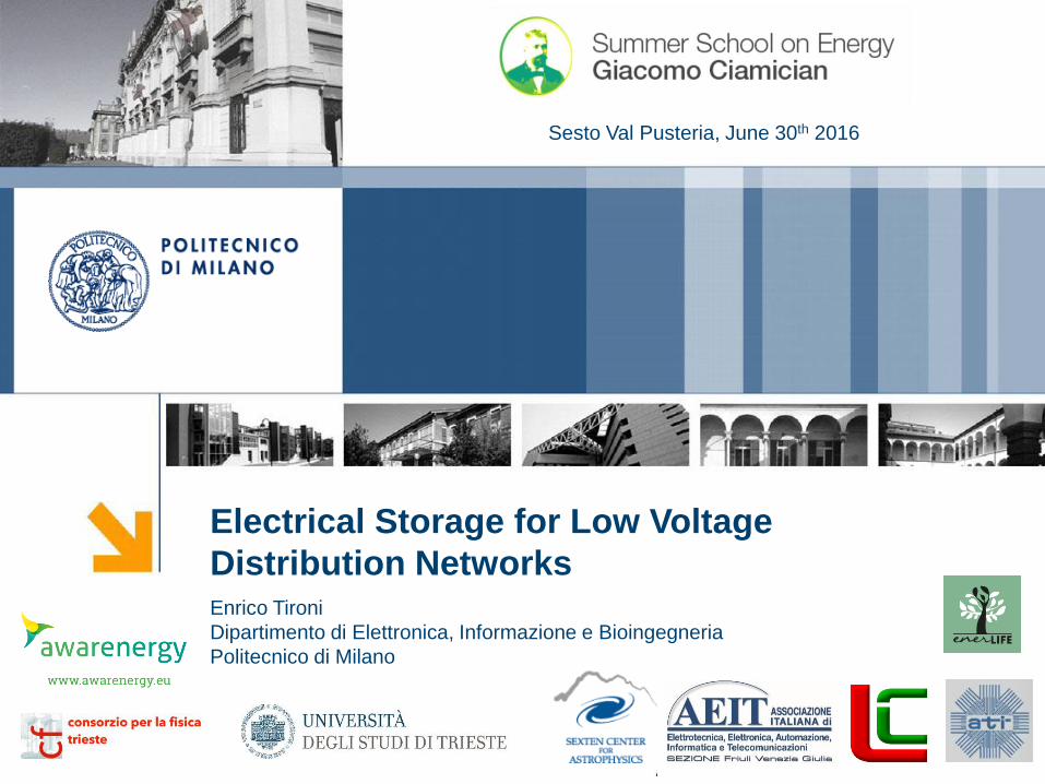
Lead acid batteries Lithium-ion batteries Supercapacitors Flywheels
Specific Energy [Wh/kg]
30 -50 90 - 190 2 - 5 10 - 50
Specific Power [W/kg]
10 -100 200 - 800 100 – 4,000 500 – 3,000
Life Cycles 200 -300 500 - 2,000 1,000,000 20 years
4
Electrical StorageParameters and Characteristics
A combination of different technologies
may be considered
Enrico Tironi [email protected]
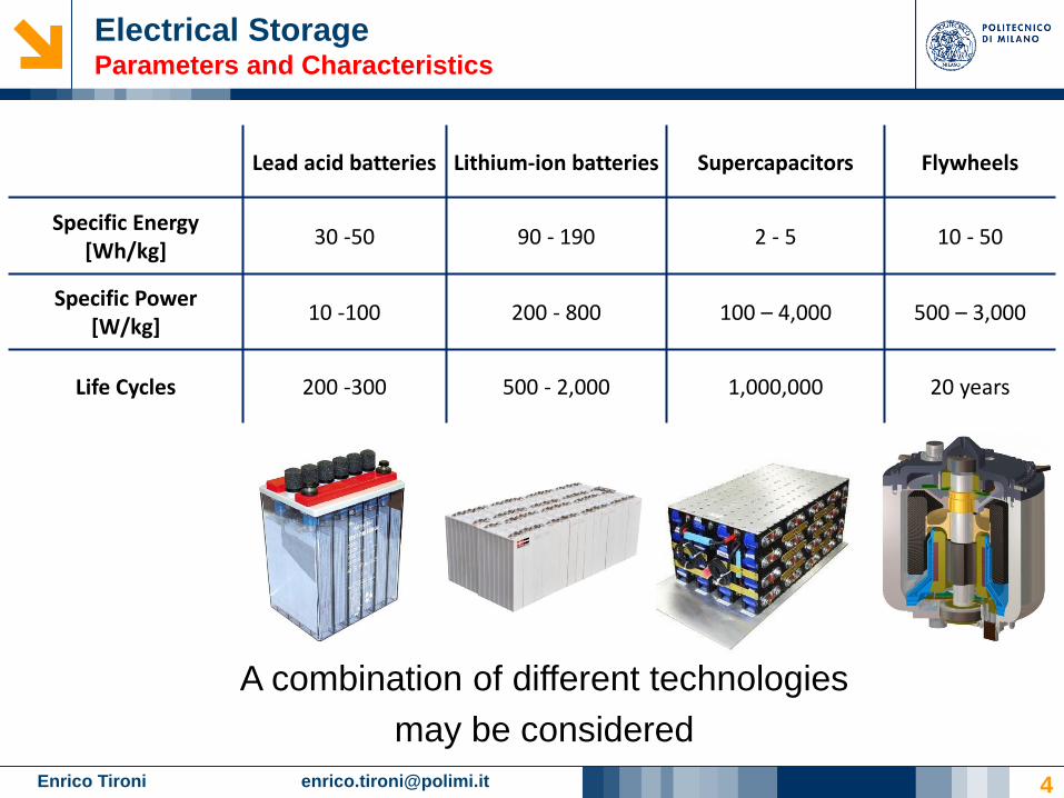
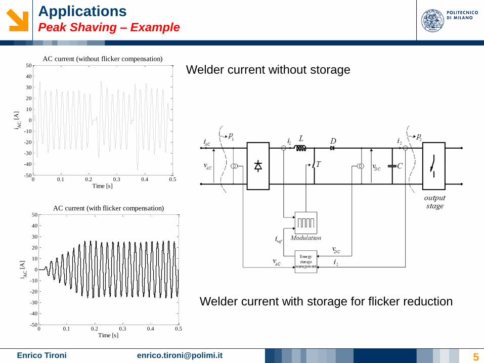
ApplicationsPeak Shaving – Example
0 0.1 0.2 0.3 0.4 0.5-50
-40
-30
-20
-10
0
10
20
30
40
50
i AC
[A
]
Time [s]
AC current (without flicker compensation)
5
0 0.1 0.2 0.3 0.4 0.5-50
-40
-30
-20
-10
0
10
20
30
40
50
i AC
[A
]
Time [s]
AC current (with flicker compensation)
Welder current without storage
Welder current with storage for flicker reduction

Enrico Tironi [email protected]
ApplicationsTime Shift – Example
6
Grid connection power: 3kW
Average consumption: 2,700kWh
Investment lifespan: 25 years
Net metering
Tax deduction: 50%
Overnight capital cost (without storage): 1,900€/kWp
Photovoltaic plant nominal power: 3kWp
Yield
Location Energy [kWh]
North 3,900
Center 4,200
South 4,500
Residential Photovoltaic plant (1/3)Parameters

Enrico Tironi [email protected]
ApplicationsTime Shift – Example
7
Residential Photovoltaic plant (2/3)Economic results – without storage
0
5.000
10.000
15.000
NorthCenter
South
NPV [€]
+ 0 %
+ 2 %
+ 4 %
6
7
8
NorthCenter
South
PBT [years]
+ 0 %
+ 2 %
+ 4 %
Self-consumption: 30%
Enrico Tironi [email protected]
ApplicationsTime Shift – Example
8
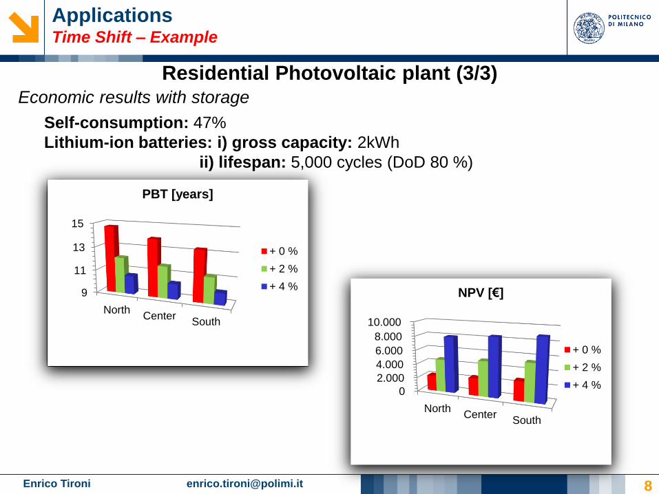
Economic results with storage
Self-consumption: 47%
Lithium-ion batteries: i) gross capacity: 2kWh
ii) lifespan: 5,000 cycles (DoD 80 %)
9
11
13
15
NorthCenter
South
PBT [years]
+ 0 %
+ 2 %
+ 4 %
0
2.000
4.000
6.000
8.000
10.000
NorthCenter
South
NPV [€]
+ 0 %
+ 2 %
+ 4 %
Residential Photovoltaic plant (3/3)

Enrico Tironi [email protected]
Average consumption: 250,060kWh
Investment lifespan: 25 years
Net metering
Overnight capital cost (without storage): 2,000€/kWp
Photovoltaic plant nominal power: 120kWp
Location: Rome
Yield: 184,796kWh
ApplicationsTime Shift – Example
9
Commercial photovoltaic plant (school rooftop) with swimming
pool (1/3)
Parameters

Enrico Tironi [email protected]
ApplicationsTime Shift – Example
10
Commercial photovoltaic plant (school rooftop) with
swimming pool (2/3)
Economic results – without storage
Self-consumption: 68 %
8
8,5
9
9,5
10
+ 0 %+ 2 %
+ 4 %
PBT [years]
0
150.000
300.000
450.000
+ 0 %+ 2 %
+ 4 %
NPV [€]
Enrico Tironi [email protected]
ApplicationsTime Shift – Example
11
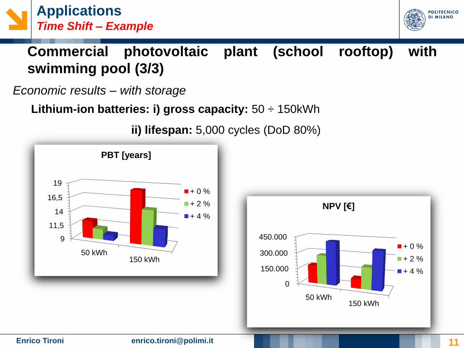
Lithium-ion batteries: i) gross capacity: 50 ÷ 150kWh
ii) lifespan: 5,000 cycles (DoD 80%)
Commercial photovoltaic plant (school rooftop) with
swimming pool (3/3)
Economic results – with storage
9
11,5
14
16,5
19
50 kWh150 kWh
PBT [years]
+ 0 %
+ 2 %
+ 4 %
0
150.000
300.000
450.000
50 kWh150 kWh
NPV [€]
+ 0 %
+ 2 %
+ 4 %

Enrico Tironi [email protected]
ApplicationsTime Shift – Example
12
Results and remarks
• The case studies presented above show that the self-consumption rate
increases when storage systems are used. Nevertheless, it is not
economically convenient
• The results obtained for the two case studies can be generalized for most
applications
• However, the use of storage brings benefits to the distribution network:
o The energy produced can be stored when the sun is shining and released
in the evening, thus bringing benefits to thermoelectric power production
o Levels the network power fluxes, thus reducing losses and enhancing
voltage regulation
• The storage systems could also enhance power quality in the active users’
network
Enrico Tironi [email protected]
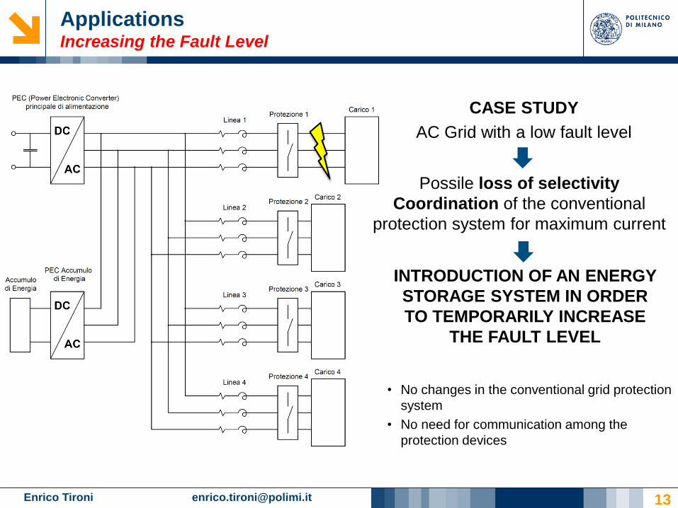
CASE STUDY
AC Grid with a low fault level
INTRODUCTION OF AN ENERGY
STORAGE SYSTEM IN ORDER
TO TEMPORARILY INCREASE
THE FAULT LEVEL
• No changes in the conventional grid protection
system
• No need for communication among the
protection devices
13
ApplicationsIncreasing the Fault Level
Possile loss of selectivity
Coordination of the conventional
protection system for maximum current
Enrico Tironi [email protected]
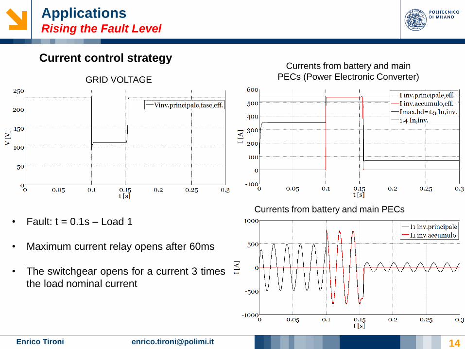
Current control strategy
GRID VOLTAGE
Currents from battery and main
PECs (Power Electronic Converter)
Currents from battery and main PECs
• Fault: t = 0.1s – Load 1
• Maximum current relay opens after 60ms
• The switchgear opens for a current 3 times
the load nominal current
14
ApplicationsRising the Fault Level

Enrico Tironi [email protected]
Different solutions
DC
AC
DC
AC
DC
AC
DC
AC
DC
AC
DC
AC
DC
AC
ESS
Load 1 Load 2 Load 3 Load n
PEC 1 PEC 2 PEC 3 PEC n
1 2 3 4
5
Multiple parallel-connected PECs with
storage systemOversizing the main PEC
• Small storage system
• The storage PEC is not necessary
• Better balance between PECs and loads
(high efficiencies)
DC
AC
Load 1 Load 2 Load 3 Load n
main PEC
• Main PEC oversized
• PEC’s operating point corresponds to
non optimal efficiency
• The network must withstand the
potential increase of the shortcircuit
power during a fault on a load
15
ApplicationsIncreasing the Fault Level
Enrico Tironi [email protected]
ApplicationsEnergy Efficiency
• Storage systems may contribute to enhance the
efficiency of systems with electrical drives
• There are two advantages:
• Design advantages
• Energy advantages
• Chance of modulation
• Energy recovery in electrical drives
16

Enrico Tironi [email protected]
Electrical DrivesEnergy Efficiency – Regenerative Brake – Design
17
Parallel-connected
Electrical drives

Enrico Tironi [email protected] 18
Storage systems for naval applicationsShip’s parameters
• Diesel generators
• 2 machines: 15.75 MVA
• 2 machines: 10.5 MVA
• Total thrusters power = 6.3 MW
• 2 thrusters: 2.2 MW
• 1 thruster: 1.9 MW

Enrico Tironi [email protected] 19
Storage systems for naval applicationsDiesel generators support during thrusters load step
0 20 40 60 80 100 120 140 160 1800
20
40
60
80
100
t [s]
P [
%]
Andamento della presa di carico dei gruppi diesel
Curva normale
Curva di emergenza
CASE STUDY
Need of a quick thrusters load
step when entering the port
Storage systems
enhances faster
thrusters load step
Diesel generators have
limited ΔP/ Δt
Diesel load step

Enrico Tironi [email protected] 20
Storage systems for naval applicationsDiesel generators support during thrusters load step
0 5 10 15 20 25 300
1
2
3
4
5
6
7Profili potenze
t [s]
Po
ten
za [
MW
]
50% of
generators
power
Load step limited by
the generators
Needed load
step
Thrusters load step
Enrico Tironi [email protected] 21
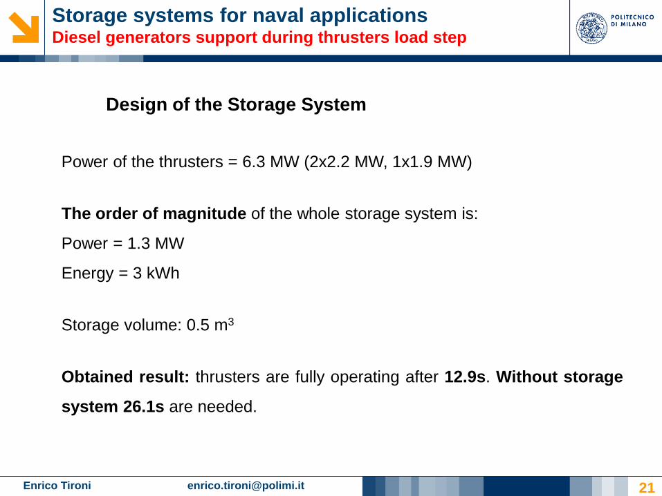
Storage systems for naval applicationsDiesel generators support during thrusters load step
Power of the thrusters = 6.3 MW (2x2.2 MW, 1x1.9 MW)
The order of magnitude of the whole storage system is:
Power = 1.3 MW
Energy = 3 kWh
Storage volume: 0.5 m3
Obtained result: thrusters are fully operating after 12.9s. Without storage
system 26.1s are needed.
Design of the Storage System

Enrico Tironi [email protected] 22
Storage systems for naval applicationsGrid support after a generation loss
CASE STUDY
Loss of one or more
generators
The energy storage system is introduced to
compensate the imbalance between the power
generated and the power requested to the grid
during the period of load reconfiguration.

Enrico Tironi [email protected] 23
Storage systems for naval applicationsGrid support after a generation loss
CASE STUDY
Loss of one or more
generators
The energy storage system is introduced to
compensate the imbalance between the power
generated and the power requested to the grid
during the period of load reconfiguration.
Order of magnitude of the storage
system
• Loss of a diesel generator with a
nominal power of 15.75MVA
• Load reconfiguration time 120ms
Power = 7 MW
Energy = 0,23 kWh
Storage volume 1 m3
Power
Performance
Enrico Tironi [email protected]
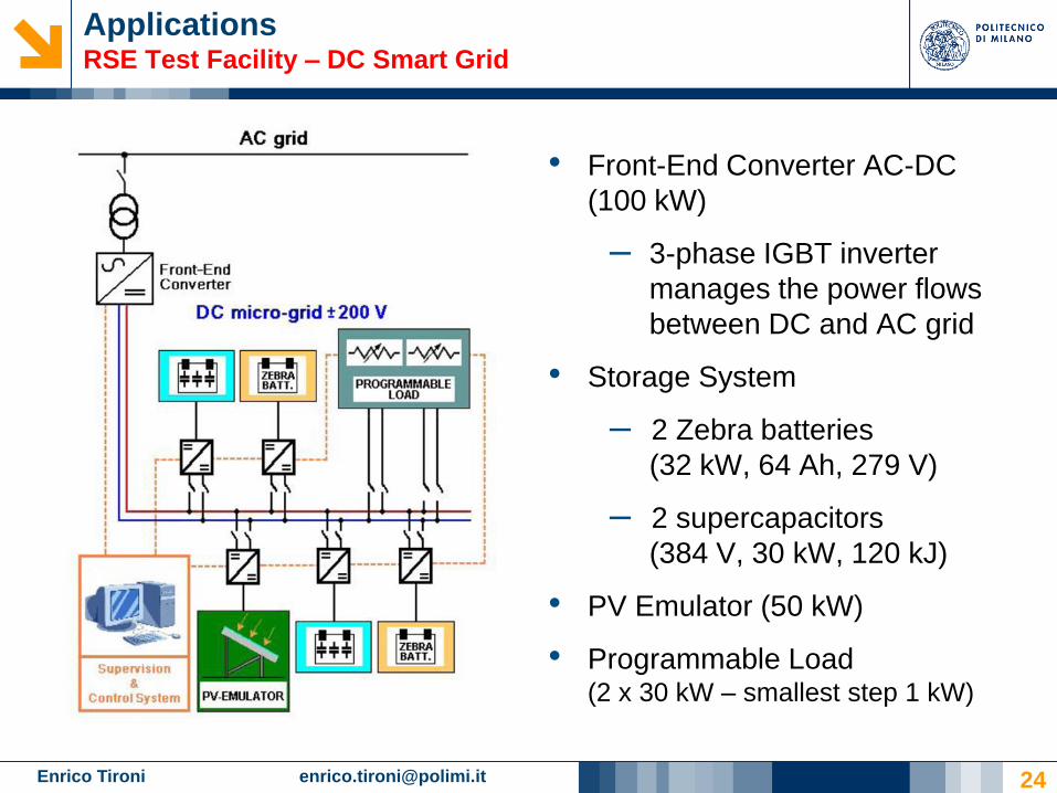
ApplicationsRSE Test Facility – DC Smart Grid
• Front-End Converter AC-DC
(100 kW)
– 3-phase IGBT inverter
manages the power flows
between DC and AC grid
• Storage System
– 2 Zebra batteries
(32 kW, 64 Ah, 279 V)
– 2 supercapacitors
(384 V, 30 kW, 120 kJ)
• PV Emulator (50 kW)
• Programmable Load(2 x 30 kW – smallest step 1 kW)
24

Enrico Tironi [email protected] 25
ApplicazioniRSE Test Facility – DC Smart Grid (power quality)
Interruption of the main
supply with variable load :
behavior of the hybrid
storage system
High quality of the Voltage
Enrico Tironi [email protected] 26
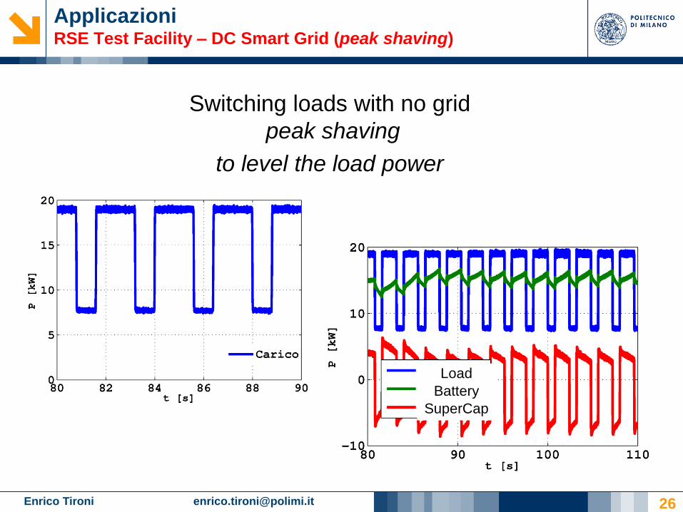
Switching loads with no grid
peak shaving
to level the load power
ApplicazioniRSE Test Facility – DC Smart Grid (peak shaving)
Load
Battery
SuperCap
Enrico Tironi [email protected] 27
Italian Regulation
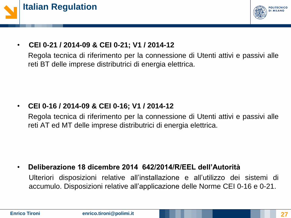
• CEI 0-21 / 2014-09 & CEI 0-21; V1 / 2014-12
Regola tecnica di riferimento per la connessione di Utenti attivi e passivi alle
reti BT delle imprese distributrici di energia elettrica.
• CEI 0-16 / 2014-09 & CEI 0-16; V1 / 2014-12
Regola tecnica di riferimento per la connessione di Utenti attivi e passivi alle
reti AT ed MT delle imprese distributrici di energia elettrica.
• Deliberazione 18 dicembre 2014 642/2014/R/EEL dell’Autorità
Ulteriori disposizioni relative all’installazione e all’utilizzo dei sistemi di
accumulo. Disposizioni relative all’applicazione delle Norme CEI 0-16 e 0-21.
Enrico Tironi [email protected] 28
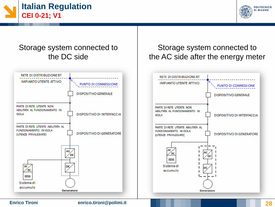
Italian RegulationCEI 0-21; V1
Storage system connected to
the DC side
Storage system connected to
the AC side after the energy meter
Enrico Tironi [email protected]
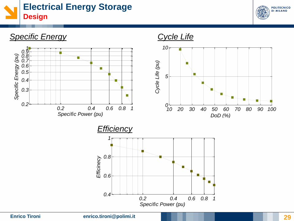
Electrical Energy StorageDesign
29
Specific Energy
Efficiency
0.2 0.4 0.6 0.8 10.4
0.6
0.8
1
Specific Power (pu)
Effic
ine
cy
Cycle Life
10 20 30 40 50 60 70 80 90 1000
5
10
DoD (%)
Cycle
Life (
pu)
0.2 0.4 0.6 0.8 10.2
0.3
0.4
0.5
0.60.70.80.9
1
Specific Power (pu)
Spe
cific
En
erg
y (
pu
)

Enrico Tironi [email protected]
jr
jr
l
j
n
klk
r
lkr
d
cCostEnergy
d
cstStorage CoCostStorageTot
plantr
storage
storage
1
1
1
1
1
00
Energy Storage SystemsCost Analysis
30
Interface Converter
External System
Storage Device
Storage System
nr replacementsLifespan (years)
Size of the storage system
Lifespan
O&M Costs
Exchanged Energy
System Efficiency
Number of Cycles
cr e dr are the inflation and the cost of
capital respectively
lstorage: Life of the storage system
Extra Costs
• Management and Monitoring Systems
• Interface Converter
• Maintenance
Electrical Storage for Low Voltage
Distribution Networks
THANK YOU!