Embed Size (px)
Citation preview
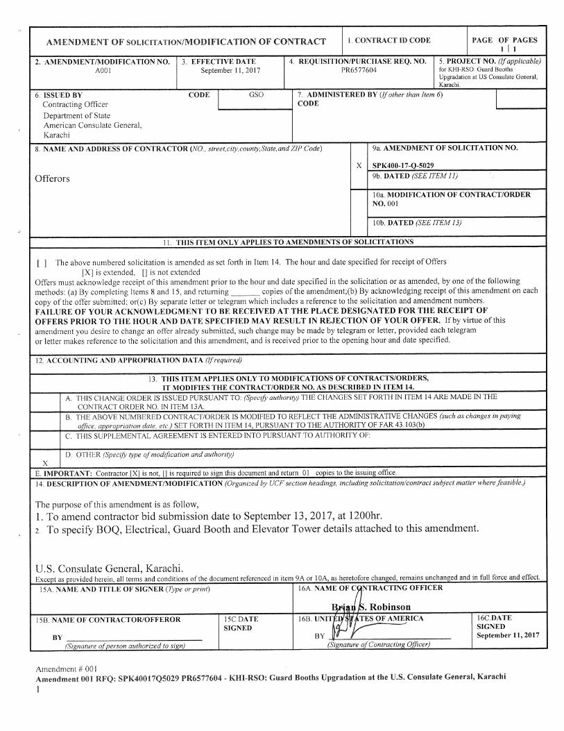

Electrical SOW:
1. All panels and subpanels to be 16 SWG and complying to IP65 protection.
2. For Elevated Towers Panels will be installed beneath the tower and for Guard booths these will
be installed adjacent to the post.
3. All Elevated towers and Guard Booths (post) to be provided with separate subpanels. Please
follow details and illustrations provided in Appendix “A”.
4. All subpanels as mentioned in para 1 will be connected to the main panels designated by
Security Gates. A Total of six main panels are required to supply power to elevated towers and
guard booth subpanels. Please follow Appendix “A” for details.
5. All Power distribution from main to the subpanels and inside the posts shall be in water tight
fitting.
6. All underground conduits to be good quality UPVC Schedule 40. G.I conduits will be used for
road crossing and concrete areas. These UPVC and G.I Conduits to buried at a minimum depth of
1feet below finished grade.
7. Where possible conduits will be run on the wall to avoid road cutting, however anything conduit
or other accessories above the ground to the G.I type with proper support.
8. All conduits to be sized in such a way that about 50% space is left after the required cable has
been pulled.
9. Install pull wires in empty raceways. Use polypropylene or monofilament plastic line with not
less than 90-kg tensile strength. Leave at least 300 mm of slack at each end of pull wire.
10. All towers and booths to be provided with lightning protection and ground pits. Follow drawing
QE-USK-14-AB-GTE16-Model for grounding and lighting protection details.
11. For Electrical lights and other accessories requirement follow drawing 23.
12. Power distribution inside each post will be through 1” G.I conduit and switches/receptacles will
be installed on metallic junction boxes. The power distribution as a whole will be bonded up to
the main panel. Junction boxes will be properly grounded. All receptacles to be three pin type.
For Phase, neutral and ground.
13. Install wire and cable with sufficient slack and flexible connections to allow for vibration of piping and equipment. Conductors at each outlet should have at least 200 mm of slack.
14. Locate pull /floor boxes at every 100 feet intervals and other 90-degree bend. All pull/ floor boxes to be water tight to prevent rain water entering into it.
15. Perform the following field tests and inspections and prepare test reports: After installing wiring devices and after electrical circuitry has been energized, test for Proper polarity and ground continuity. Test and verify GFCI operation. Measure all cables insulation resistance.
16. Remove malfunctioning units, replace with new units, and retest as specified above.
APPENDIX “A”
US CONSULATE KARACHI, PAKISTAN
BILL OF MATERIAL & DESIGN
ELECTRICAL POWER DISTRIBUTION PANEL
FOR NCC KARACHI ELEVATED TOWERS AND GUARD BOOTHS
Note: All illustrations, breakers quantities and sizes provided in this Appendix are the minimum requirement and provided
for basic understanding of the Required Power Distribution System. It is responsibility of the contractor to thoroughly
check all the required material for this job and add any component which can increase safety and security of our system.

S U M M A R Y
Total Panels
Main Panel
Sub Panels
Description Quantity
Total Quantity of Main Distribution panel 06
Total Quantity of Sub panels for Elevated posts & Guard Booths 23
Total Quantity of electrical power distribution panels 29
Description Quantity
Main power distribution panel for SCAC O1
Main power distribution panel for MCAC O1
Main power distribution panel for CCAC O1
Main power distribution panel for RCAC O1
Main power distribution panel for Courier gate O1
Main power distribution panel for Utility-2 O1
Total Quantity 06
Description Quantity
Sub panels for Guard Booths 18
Sub panel for Elevated posts 05
Total Quantity 23

PANEL SPECFICATIONS AND DETAILS
MAIN POWER DISTRIBUTION PANEL FOR S CAC
MAIN POWER DISTRIBUTION PANEL FOR M CAC
S. No. Description Size Qty Make
1 MCCB 3pole 60 Amps 01 Terasaki or Equivalent
2 MCCB 3pole 20 Amps 07 Terasaki or Equivalent
3 MCB 1pole 20Amps 02 Schneider electric or Equivalent
4 Neutral strip (Copper) 60 Amps 12 Hole Local
5 Ground strip (Copper) 60 Amps 12 Hole Local
6 Panel gauge 16 SWG As per size 01 Local
7 Bus bar Copper (As per Panel load.) - 03 Local
8 Acrylic sheet 5mm 01 Local
S. No. Description Size Qty Make
1 MCCB 3pole 60 Amps 01 Terasaki or Equivalent
2 MCCB 3pole 20 Amps 10 Terasaki or Equivalent
3 MCB 1pole 20Amps 01 Schneider electric or Equivalent
4 Neutral strip (Copper) 60 Amps 12 Hole Local
5 Ground strip (Copper) 60 Amps 12 Hole Local
6 Panel gauge 16 SWG As per size 01 Local
7 Bus bar Copper (As per Panel load.) - 03 Local
8 Acrylic sheet 5mm 01 Local

MAIN POWER DISTRIBUTION PANEL FOR C CAC
MAIN POWER DISTRIBUTION PANEL FOR R CAC
S. No. Description Size Qty Make
1 MCCB 3pole 60 Amps 01 Terasaki or Equivalent
2 MCCB 3pole 20 Amps 03 Terasaki or Equivalent
3 MCB 1pole 20Amps 01 Schneider electric or Equivalent
4 Neutral strip (Copper) 60 Amps 12 Hole Local
5 Ground strip (Copper) 60 Amps 12 Hole Local
6 Panel gauge 16 SWG As per size 01 Local
7 Bus bar Copper (As per Panel load.) - 03 Local
8 Acrylic sheet 5mm 01 Local
S. No. Description Size Qty Make
1 MCCB 3pole 60 Amps 01 Terasaki or Equivalent
2 MCCB 3pole 20 Amps 05 Terasaki or Equivalent
3 MCB 1pole 20Amps 01 Schneider electric or Equivalent
4 Neutral strip (Copper) 60 Amps 12 Hole Local
5 Ground strip (Copper) 60 Amps 12 Hole Local
6 Panel gauge 16 SWG As per size 01 Local
7 Bus bar Copper (As per Panel load.) - 03 Local
8 Acrylic sheet 5mm 01 Local
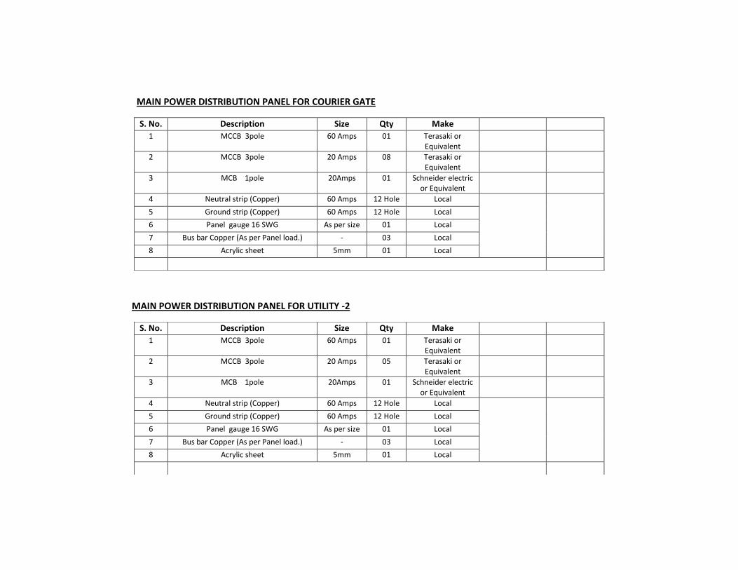
MAIN POWER DISTRIBUTION PANEL FOR COURIER GATE
MAIN POWER DISTRIBUTION PANEL FOR UTILITY -2
S. No. Description Size Qty Make
1 MCCB 3pole 60 Amps 01 Terasaki or Equivalent
2 MCCB 3pole 20 Amps 08 Terasaki or Equivalent
3 MCB 1pole 20Amps 01 Schneider electric or Equivalent
4 Neutral strip (Copper) 60 Amps 12 Hole Local
5 Ground strip (Copper) 60 Amps 12 Hole Local
6 Panel gauge 16 SWG As per size 01 Local
7 Bus bar Copper (As per Panel load.) - 03 Local
8 Acrylic sheet 5mm 01 Local
S. No. Description Size Qty Make
1 MCCB 3pole 60 Amps 01 Terasaki or Equivalent
2 MCCB 3pole 20 Amps 05 Terasaki or Equivalent
3 MCB 1pole 20Amps 01 Schneider electric or Equivalent
4 Neutral strip (Copper) 60 Amps 12 Hole Local
5 Ground strip (Copper) 60 Amps 12 Hole Local
6 Panel gauge 16 SWG As per size 01 Local
7 Bus bar Copper (As per Panel load.) - 03 Local
8 Acrylic sheet 5mm 01 Local

SUB PANEL FOR ELEVATED TOWERS
SUB PANEL FOR GUARD BOOTHS
S. No. Description Size Qty Make
1 MCB 3pole 20 Amps 01 Schneider electric or Equivalent
2 MCB 1pole 10 Amps 02 Schneider electric or Equivalent
3 MCB 1pole 20 Amps 01 Schneider electric or Equivalent
4 GFCI/ RCCB 20 Amps 01 Schneider electric or Equivalent
5 Neutral strip (Copper) 20 Amps 06 Hole Local
6 Ground strip (Coper) 20 Amps 06 Hole Local
7 Panel gauge 16 SWG 24”x 18” 01 Local
8 Bus bar Copper (As per Amp. Rating) - 03 Local
9 Acrylic sheet 5mm 01 Local
S. No. Description Size Qty Make
1 MCB 3pole 20 Amps 01 Schneider electric or Equivalent
2 MCB 1pole 10 Amps 04 Schneider electric or Equivalent
3 MCB 1pole 20 Amps 01 Schneider electric or Equivalent
4 GFCI/ RCCB 20 Amps 02 Schneider electric or Equivalent
5 Neutral strip (Copper) 30 Amps 10 Hole Local
6 Ground strip (Coper) 30 Amps 10 Hole Local
7 Panel gauge 16 SWG 24”x 18” 01 Local
8 Bus bar Copper (As per Amp. Rating) - 03 Local
9 Acrylic sheet 5mm 01 Local
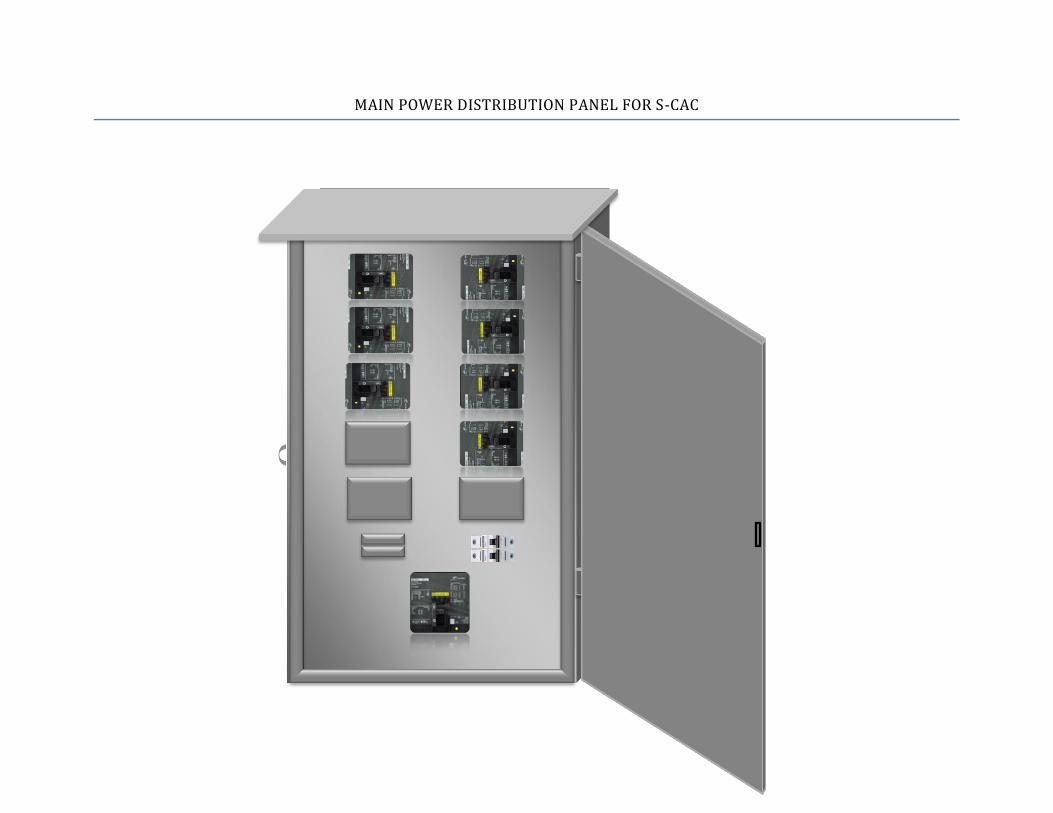
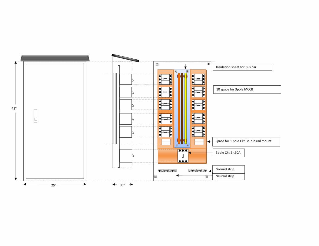
MAIN POWER DISTRIBUTION PANEL FOR S-CAC

MAIN POWER DISTRIBUTION PANEL FOR S-CAC (INTERNAL VIEW)
a
3pole Ckt.Br.60A
10 space for 3pole MCCB
Insulation sheet for Bus bar
Neutral strip
Ground strip
25”
42”
‘”
06”
Space for 1 pole Ckt.Br. din rail mount

MAIN POWER DISTRIBUTION PANEL FOR M-CAC
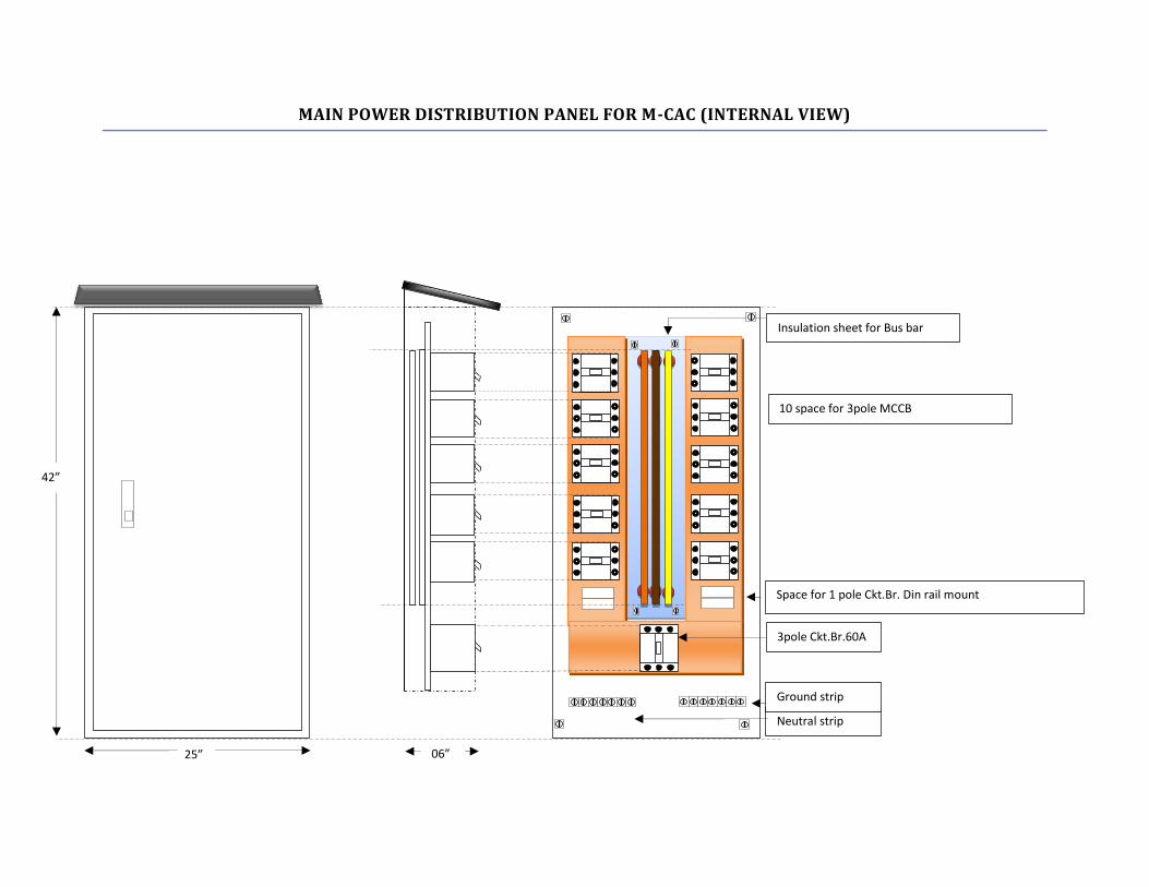
MAIN POWER DISTRIBUTION PANEL FOR M-CAC (INTERNAL VIEW)
a
3pole Ckt.Br.60A
10 space for 3pole MCCB
Insulation sheet for Bus bar
Neutral strip
Ground strip
25”
42”
‘”
06”
Space for 1 pole Ckt.Br. Din rail mount

MAIN POWER DISTRIBUTION PANEL FOR C-CAC
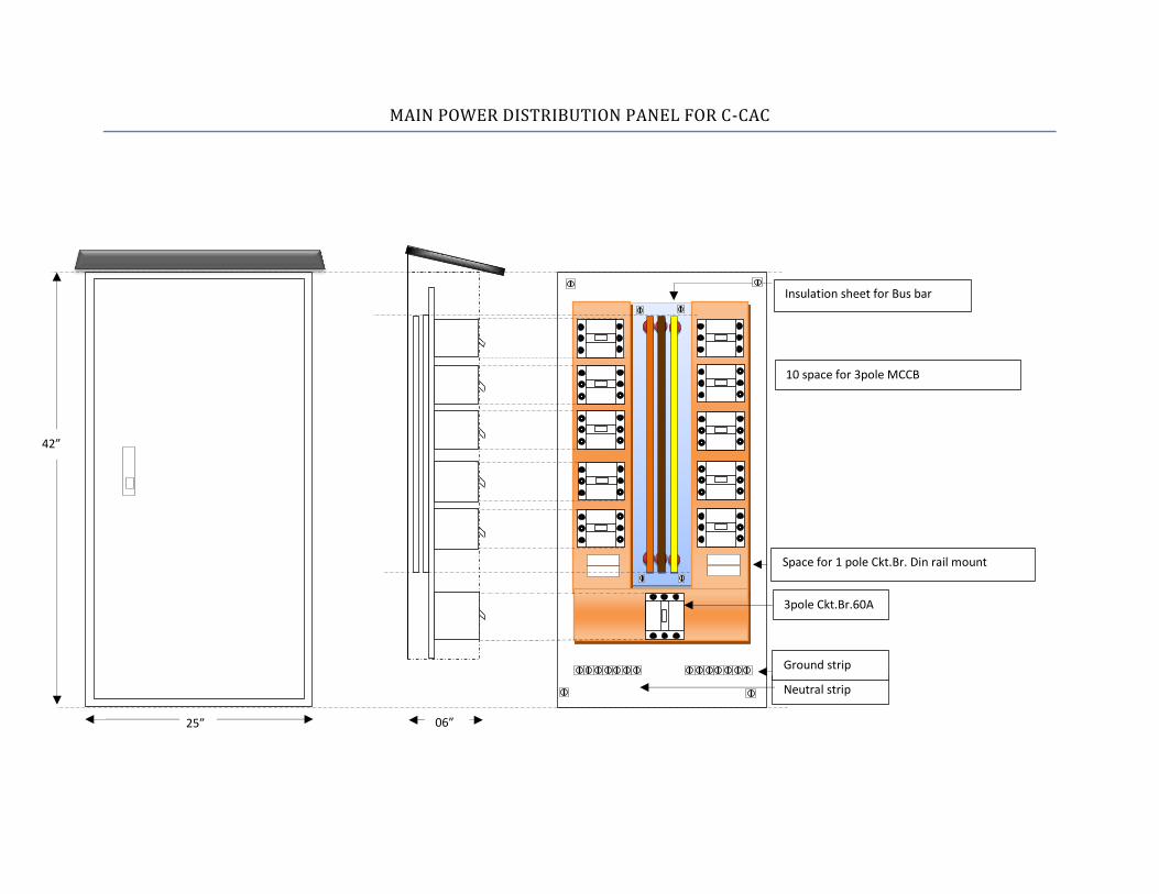
MAIN POWER DISTRIBUTION PANEL FOR C-CAC
a
3pole Ckt.Br.60A
10 space for 3pole MCCB
Insulation sheet for Bus bar
Neutral strip
Ground strip
25”
42”
‘”
06”
Space for 1 pole Ckt.Br. Din rail mount

MAIN POWER DISTRIBUTION PANEL FOR R-CAC

MAIN POWER DISTRIBUTION PANEL FOR R-CAC
a
3pole Ckt.Br.60A
10 space for 3pole MCCB
Insulation sheet for Bus bar
crylic sheet Bus bar protection
Neutral strip
Ground strip
25”
42”
‘”
06”
Space for 1 pole Ckt.Br. din rail mount

MAIN POWER DISTRIBUTION PANEL FOR COURIER GATE

a
3pole Ckt.Br.60A
10 space for 3pole MCCB
Insulation sheet for Bus bar
Neutral strip
Ground strip
25”
42”
‘”
06”
Space for 1 pole Ckt.Br. din rail mount

MAIN POWER DISTRIBUTION PANEL FOR UTILITY-2
a
3pole Ckt.Br.60A
10 space for 3pole MCCB
Insulation sheet for Bus bar
Neutral strip
Ground strip
25”
42”
‘”
06”
Space for 1 pole Ckt.Br. din rail mount

SUB PANEL FOR ELEVATED TOWERS
Rubber seal for IP 65
Collar for water drain
Blank space
LOTO

SUB PANEL FOR ELEVATED TOWERS
S. pole GFCI/ RCCB
3P.blank space
Neutral strip.30A
Bus Bar
3pole Mcb.20A
Ground strip.30A
Insulation sheet
Bus bar Isolator
24”
18”
RCCB 20A RCCB 20A 10A 10A 10A 10A 20A
Ground strip.30A
Blank space

SUB PANEL FOR GUARD BOOTHS
Rubber seal for IP 65
Collar for water drain
Blank space
LOTO

SUB PANEL FOR GUARD BOOTHS
S. pole GFCI/ RCCB
3P.blank space
Neutral strip.20A
Bus Bar 50 Amps
3pole Mcb.20A
Ground strip.30A
Insulation sheet
5mm
Bus bar Isolator
24”
18”
RCCB 20A 20A 10A 10A
Ground strip.30A
Blank space
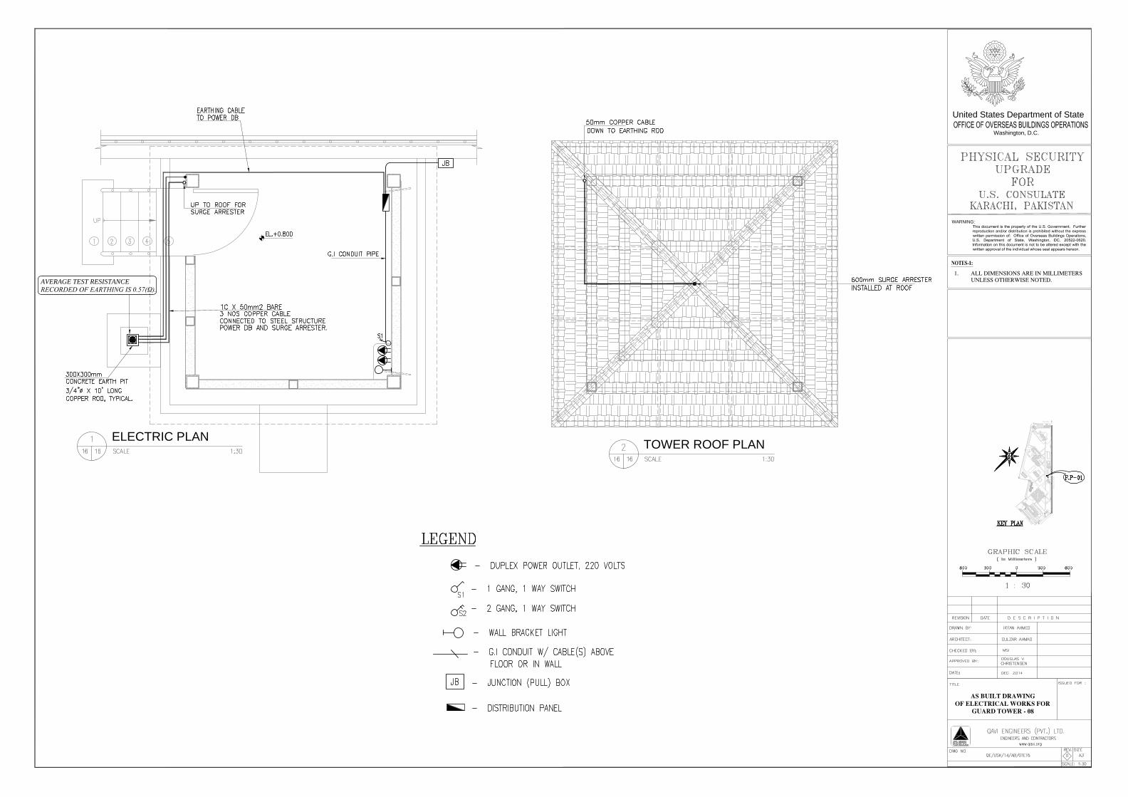
ELECTRIC PLAN
Washington, D.C.
United States Department of State
WARNING:
TOWER ROOF PLAN
AVERAGE TEST RESISTANCERECORDED OF EARTHING IS 0.57(Ω).

S.No Post Name Sub panel to Post Interior Wire Size Remarks1 Elevated Tower 200 ft 8 AWG/ 10 sqmm 12 AWG/ 4 sqmm
2 Guard Booth 300 ft 8 AWG/ 10 sqmm 12 AWG/ 4 sqmm
3 Guard Booth 115 ft 8 AWG/ 10 sqmm 12 AWG/ 4 sqmm
4 Guard Booth 150 ft 8 AWG/ 10 sqmm 12 AWG/ 4 sqmm
S.No Post Name Sub panel to Post Interior Wire Size Remarks
1 Elevated Tower80 ft
8 AWG/ 10 sqmm 12 AWG/ 4 sqmm
2 Elevated Tower100 ft
8 AWG/ 10 sqmm 12 AWG/ 4 sqmm
3 Guard Booth150 ft
8 AWG/ 10 sqmm 12 AWG/ 4 sqmm
4 Guard Booth230 ft
8 AWG/10 sqmm 12 AWG/ 4 sqmm
5 Guard Booth 190 ft
8 AWG/ 10 sqmm 12 AWG/ 4 sqmm
6 Guard Booth120 ft
8 AWG/ 10 sqmm 12 AWG/ 4 sqmm
7 Guard Booth280 ft
8 AWG/ 10 sqmm 12 AWG/ 4 sqmm
8 Guard Booth130 ft
8 AWG/ 10 sqmm 12 AWG/ 4 sqmm
9 Guard Booth330 ft
8 AWG/ 10 sqmm 12 AWG/ 4 sqmm
10 Guard Booth 130 ft 8 AWG/ 10 sqmm 12 AWG/ 4 sqmm
S.No Post Name Sub panel to Post Interior Wire Size Remarks1 Elevated Tower 145 ft 8 AWG/ 10 sqmm 12 AWG/ 4 sqmm
Note: All cable lengths provided here are an approximation. Contractor is responsible
to properly verify and quantify exact cable lengths for this project
S.No Post Name Sub panel to Post Interior Wire Size Remarks1 Elevated Tower 150 ft 8 AWG/ 10 sqmm 12 AWG/ 4 sqmm
Main panel to Post Sub Panel Length With Wire Size
Courier Gate Area Security Posts
Main Source to main panel distance : 70 feet
Cable Size : 6 AWG x 5 nos
Main panel to Post Sub Panel Length With Wire Size
C-CAC Area Security Posts
Main Source to main panel distance : 70 feet
Cable Size : 6 AWG x 5 nos
Main panel to Post Sub Panel Length With Wire Size
S-CAC Area Security Posts
Main Source to main panel distance : 60 feet
Cable Size : 6 AWG x 5 nos
M-CAC Area Security Posts
Main Source to main panel distance : 30 feet
Cable Size : 6 AWG x 5 nos
Main panel to Post Sub Panel Length With Wire Size
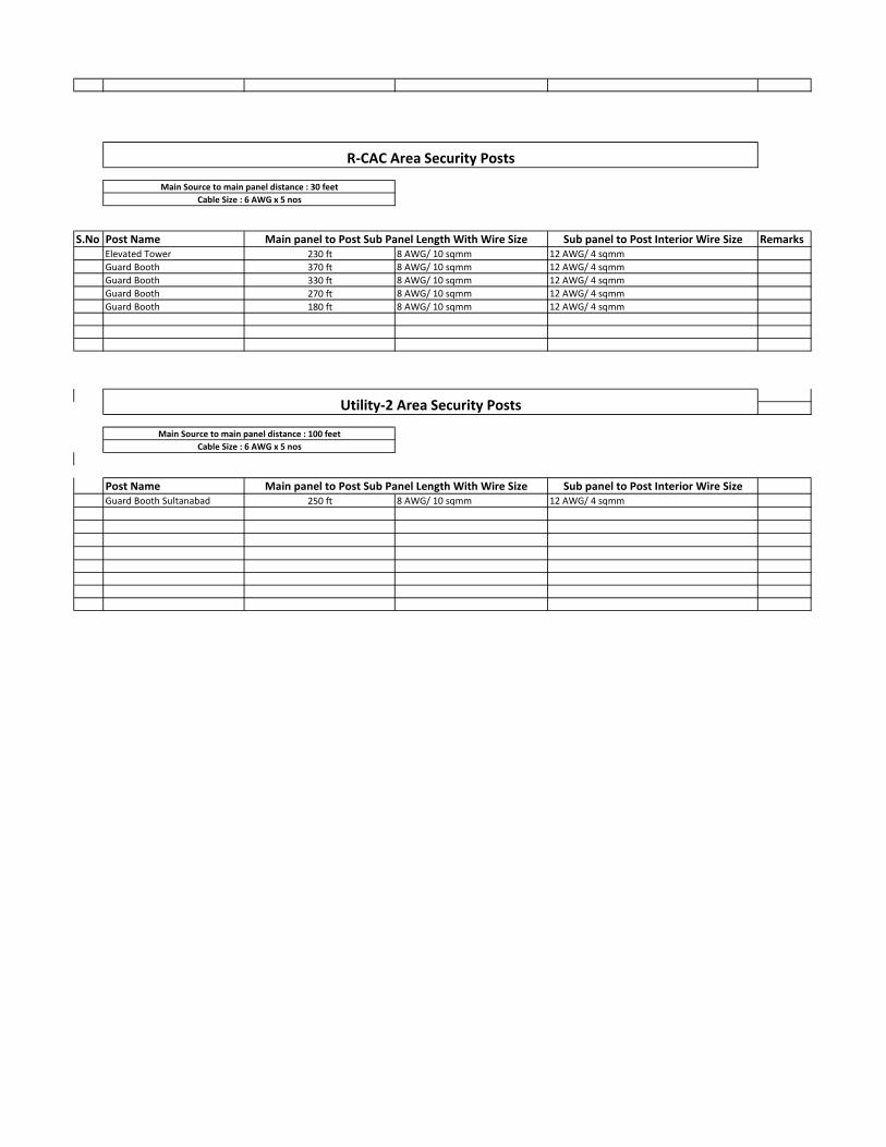
S.No Post Name Sub panel to Post Interior Wire Size RemarksElevated Tower 230 ft 8 AWG/ 10 sqmm 12 AWG/ 4 sqmm
Guard Booth 370 ft 8 AWG/ 10 sqmm 12 AWG/ 4 sqmm
Guard Booth 330 ft 8 AWG/ 10 sqmm 12 AWG/ 4 sqmm
Guard Booth 270 ft 8 AWG/ 10 sqmm 12 AWG/ 4 sqmm
Guard Booth 180 ft 8 AWG/ 10 sqmm 12 AWG/ 4 sqmm
Post Name Sub panel to Post Interior Wire SizeGuard Booth Sultanabad 250 ft 8 AWG/ 10 sqmm 12 AWG/ 4 sqmm
Utility-2 Area Security Posts
Main Source to main panel distance : 100 feet
Cable Size : 6 AWG x 5 nos
Main panel to Post Sub Panel Length With Wire Size
Cable Size : 6 AWG x 5 nos
Main panel to Post Sub Panel Length With Wire Size
R-CAC Area Security Posts
Main Source to main panel distance : 30 feet

SITE LOCATION PLAN
Washington, D.C.
United States Department of State
WARNING:
CHANCERY
S
T
A
F
F
H
O
U
S
I
N
G
CCAC
SCAC
RCAC
MCAC
M
S
G
Q
R
E
S
I
D
E
N
C
E
U
T
I
L
I
T
Y
B
U
I
L
D
I
N
G
G
S
O
W
O
R
K
S
H
O
P
&
W
A
R
E
H
O
U
S
E
MAI KOLACHI ROAD
NLC
S
ID
E
M
.
T
.
K
H
A
N
S
I
D
E
RANGERS
BUILDING
MCAC
C
C
A
C
OP-6 OP-5
7
2
.
8
1
3
.
3
1
3
5
.
5
9
.
1
5
9
.1
2
9
5
.2
2
0
.
7
9
6
.7
1
9
.0
1
9
.0
87.4
1
1
.
1
499.1
7
1
.
6
8
.
8
1
6
0
.0
1
2
8
.3
2
0
.
9
1
1
3
.
9
27.649.9148.895.632.537.637.448.2 21.3
7
.0
M
O
S
Q
U
E
Elevated
Tower
Demolish
existing
Guard
Booths
x 4
Guard
Booths
x 4
Elevated
Tower
Semi-permanent
Guard
Booth
x 4
Elevated
Tower
x 2
Guard
Booth
x 4
Elevated
Tower
Guard
Booth
x 2
at
sultanabad
side

Washington, D.C.
United States Department of State
WARNING:
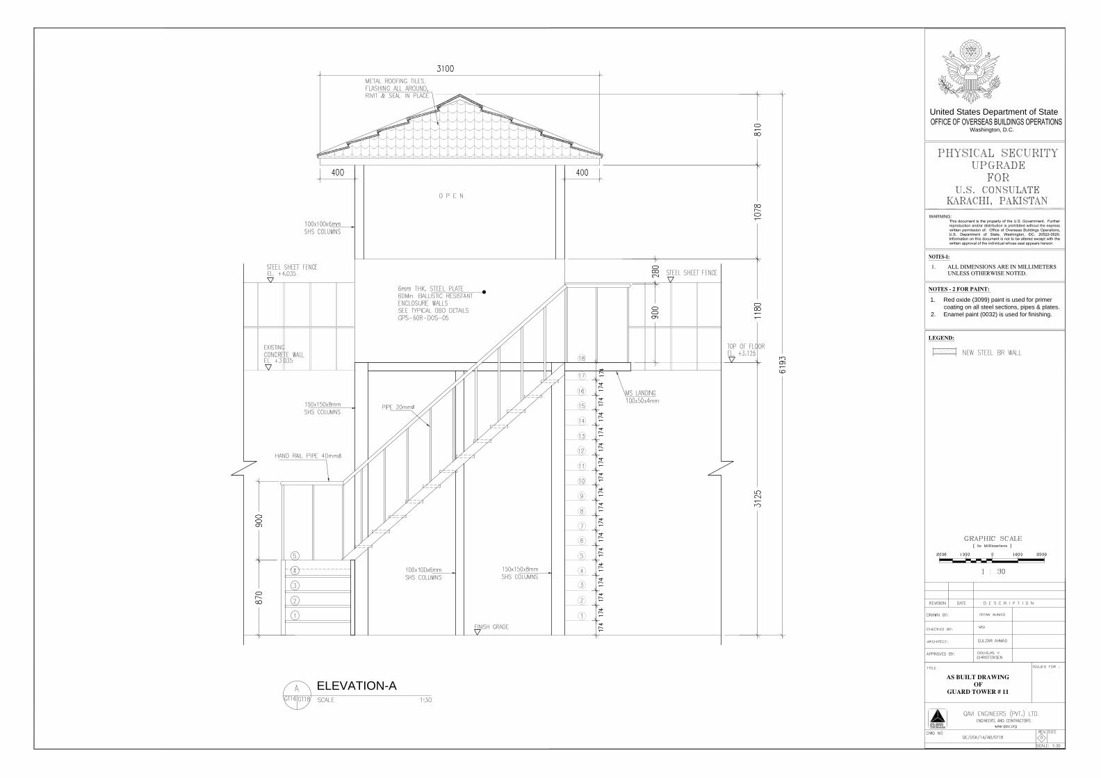
1. Red oxide (3099) paint is used for primer
coating on all steel sections, pipes & plates.
2. Enamel paint (0032) is used for finishing.
BASE FLOOR PLAN GUARD TOWER FLOOR PLAN

TOWER ROOF PLAN
Washington, D.C.
United States Department of State
WARNING:
1. Red oxide (3099) paint is used for primer
coating on all steel sections, pipes & plates.
2. Enamel paint (0032) is used for finishing.
STEP DETAIL
MS LANDING DETAIL
STAIR DETAIL
Washington, D.C.
United States Department of State
WARNING:
1. Red oxide (3099) paint is used for primer
coating on all steel sections, pipes & plates.
2. Enamel paint (0032) is used for finishing.
ELEVATION-A
Washington, D.C.
United States Department of State
WARNING:
1. Red oxide (3099) paint is used for primer
coating on all steel sections, pipes & plates.
2. Enamel paint (0032) is used for finishing.
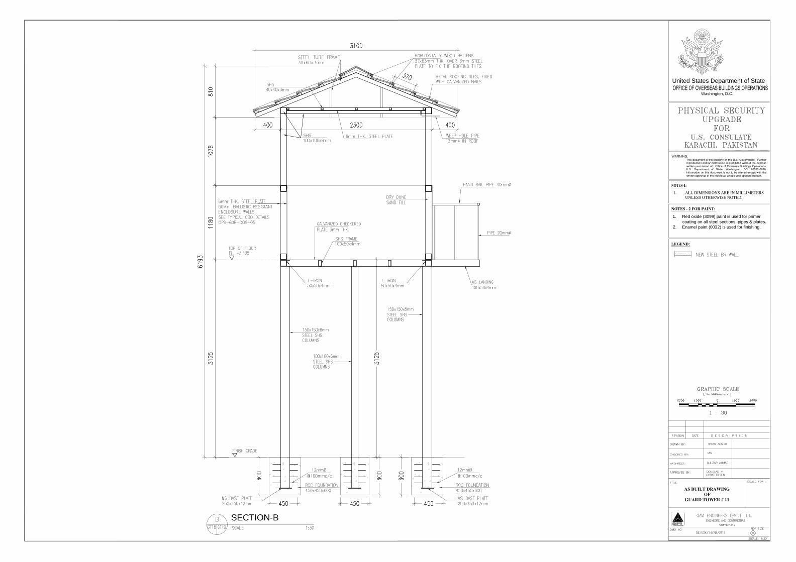
SECTION-B

TOWER FLOOR PLAN
Washington, D.C.
United States Department of State
WARNING:
1. Red oxide (3099) paint is used for primer
coating on all steel sections, pipes & plates.
2. Enamel paint (0032) is used for finishing.
TOWER ROOF PLAN
STEP DETAIL
STAIR DETAIL

FRONT ELEVATION SECTION
Washington, D.C.
United States Department of State
WARNING:
1. Red oxide (3099) paint is used for primer
coating on all steel sections, pipes & plates.
2. Enamel paint (0032) is used for finishing.