Embed Size (px)
Citation preview

Electrical Resistivity
Measurements,
Midway and Kure AtollsGEOLOGICAL SURVEY PROFESSIONAL PAPER 680-D

Electrical Resistivity
Measurements,
Midway and Kure AtollsBy GEORGE V. KELLER
GEOLOGY OF THE MIDWAY AREA, HAWAIIAN ISLANDS
GEOLOGICAL SURVEY PROFESSIONAL PAPER 680-D
Electrical resistivity measurements are used
to estimate porosity of reef sediments at
various depths
UNITED STATES GOVERNMENT PRINTING OFFICE, WASHINGTON : 1969

UNITED STATES DEPARTMENT OF THE INTERIOR
WALTER J. HICKEL, Secretary
GEOLOGICAL SURVEY
William T. Pecora, Director
For sale by the Superintendent of Documents, U.S. Government Printing Office Washington, D.C. 20402 - Price 25 cents (paper cover)

CONTENTS
Page Abstract--.-.-.---_________________________________________________________ D1Introduction and acknowledgments___________________._______________________ 1Sample measurements_______________________________________________________ 1Well-logging measurements in place.__________________________________________ 4Resistivity soundings______________________________________________________ 6Summary. _________________________________________________________________ 7References cited.___________________________________________________________ 8
ILLUSTRATIONS
PageFIGURE 1. Lithologic, apparent porosity, and formation-resistivity-factor logs from the Sand Island hole cores and a resis
tivity log from the same drill hole___._---_-_--____________-_-___-___________-___--_--_-_--____---_- D22. Lithologic, apparent porosity, and formation-resistivity-factor logs from the Reef hole cores.___________________ 33. Scatter-plot showing correlation between formation resistivity factor and apparent porosity for carbonate samples
from Reef and Sand Island holes..________________________________________________________________ 44. Histograms showing distributions of computed values for apparent porosity, wet-bulk density, and apparent grain
density for carbonate samples resaturated with brine-_----____-__-______-_-___--_---_-_-_------------- 55. Graph showing average relations between porosity and electrical resistivity_________________________________ 56. Graph showing resistivity sounding data from Sand, Eastern, and Green Islands___-_______---_-_-__---_---- 6
in


GEOLOGY OF THE MIDWAY AREA, HAWAIIAN ISLANDS
ELECTRICAL RESISTIVITY MEASUREMENTS, MIDWAY AND KURE ATOLLS
By GEORGE V.
ABSTRACT
Electrical resistivity measurements made on recovered core samples, by drill-hole logging, and by surface sounding have been used to estimate the porosity of carbonate sediments com posing Midway and Kure atolls in the western part of the Hawaiian Islands. The porosities within the first few tens of feet of the surface generally exceed 50 percent by volume but decrease by a factor of two or three at a depth of 500-1,000 feet. The use of resistivity measurements seems to provide a better estimate of porosity than porosity measurements made directly on recovered core samples because of difficulties in collecting an unbiased sample of high-porosity materials.
INTRODUCTION AND ACKNOWLEDGMENTS
The drilling of two holes through reef sediments into underlying basalt on Midway atoll, Hawaii, has been described by Ladd, Tracey, and Gross (1967). In addi tion to the other scientific studies carried out in conjunc tion with this drilling project, electrical resistivity measurements were made of the carbonate sediments. Some measurements were made on the sediments in place using surface-based and drill-hole measurement techniques, and other measurements were made oil the samples recovered from the drill holes. The purpose was to provide information on the possible applicability of electrical resistivity surveys to the study of reef sedimentation.
The electrical properties of limestones, and in partic ular of reef limestones, have been the subject of several studies related to petroleum exploration. Archie (1952) indicated that the relation between electrical resistivity and water-filled porosity in carbonate rocks is essen tially the same as that in sandstones, except that the complex pore structures in carbonates cause a greater variability in the resistivity. McCrossan (1961) studied resistivities from electric logs made in calcareous inter- reef deposits in Alberta and found that resistivity val ues seemed to be related to the proximity to reef struc tures. Pirson (1963) pointed out that the variety of pore structures in carbonate rocks should have some effect on the behavior of electrical properties. He indi-
1 Colorado School of Mines, Golden, Colo.
cated that it is important to distinguish between matrix porosity and structural porosity. All the work reported in the literature, however, has dealt with ancient car bonates, where it is reasonable to expect that recrystalli- zation and diastrophism may have modified the original pore structures markedly. The drilling at Midway atoll offered the opportunity to study electrical properties of reef rocks having a minimum of such modifications.
I am indebted to Harry S. Ladd, U.S. Geological Sur vey, for making these studies possible, and to the Hawaii Institute of Geophysics, University of Hawaii, under whose auspices the program in the Midway area was carried out. The work was supported by the Na tional Science Foundation (grant No. GP4728) in coop eration with the U.S. Geological Survey and the U.S. Office of Naval Research.
SAMPLE MEASUREMENTS
Two holes were drilled on Midway atoll: one on Sand Island, which reached basalt at a depth of 516 feet, and the other just inside the reef on the north side of the lagoon, which reached basalt at a depth of 1,261 feet (Ladd and others, 1967). Cores were cut with a diamond drill with a rubber-sleeve core barrel, which preserved even the friable material for recovery at the surface. Most cores were 3 inches in diameter. A sea-water base drilling mud was used.
Approximately 160 small samples were selected from the 1,700 feet of carbonate core material for studies of electrical properties. The samples were air dried and cut to regular shapes for electrical properties studies. Samples were resaturated with a 0.5 normal solution of sodium chloride by vacuum boiling; that is, the samples were immersed in the saturating solution and placed in a vacuum for 12 hours. The vacuum chamber was then opened to atmospheric pressure so that the saturating solution would enter the pore structures of the samples.
After saturation, the samples were stored in the 0.5 normal solution of sodium chloride for 2 months to permit the extra salts remaining in the pore structure from the original water content to redistribute by diffu-
351-472 6Dl

D2 GEOLOGY OF THE MIDWAY AREA, HAWAIIAN ISLANDS
sion. The wet samples were then weighed, and their volumes were determined by their loss in weight on sus pension in water. The electrical resistance between op posite faces of the samples was measured by using a two-terminal method: the roughly cylindrical samples were placed between two metal plates which provided the current. The contact between the plates and the rock was made through felt saturated with salt water. Kesist- ance measurements were made at a frequency of 1,000 cycles per second to avoid electrode polarization problems.
After the resistance measurements were made, the water content of the samples was determined by measur ing the loss in weight on drying at a temperature of
Electrical resistivity was determined from the resist ance measurements and from the dimensions of the samples by using the usual formula :
(1)where R is the measured resistance, A is the cross-sec tional area through which current flows, L is the thick ness of the core sample in the direction of current flow,
Ww is the weight of the sample when water saturated, and Ws is the weight of the same sample suspended in water. The ratio of volume to length was used as the cross-sectional area of a sample because the samples were irregular in outline and the cross-sectional area could not be determined directly.
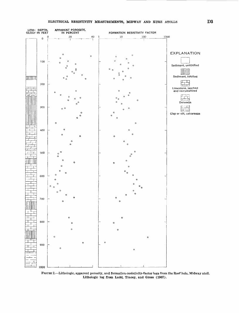
The results of these measurements are given in figures 1 and 2. The resistivity measurements are expressed in terms of a formation resistivity factor, which is the ratio of measured rock resistivity to the resistivity of the saturating water. Lithologic logs are from Ladd, Tracey, and Gross (1967). As can be seen, there is no obvious correlation between values for the formation resistivity factor and the lithology.
Both the formation resistivity factor and the ap parent porosity (the volume fraction of water absorbed by the samples on resaturation) vary widely. Calculated apparent porosities range from about 4 percent to about 60 percent, and the formation resistivity factor corre spondingly ranges from 1.7 to 150. The correlation between the formation resistivity factor and the apparent porosity (water content) for carbonate sam ples is given in figure 3.
LITH- DEPTH, APPARENT POROSITY. OLOGY IN FEET IN PERCENT
0 20 40
IIIIIIIIIJ
,,^Ini u
^i--1_. . _
1L 100
200
1
300
- 400
Knn
1 ' 1 ' o
0
o
o °_n
0
0
°
° 0
0
° 0-°° 0
o
° o o o 0 ° °0
_ o
g ° o0
0 0
° ' 0 0 -.
\° 8°°<* 0
°o o
0
, 0 1 , 1 ,
FORMATION RESISTIVITY FACTOR10 100 1000 0
RESISTIVITY. IN OHM-METERS 2468
FIGURE 1. Lithologic, apparent porosity, formation-resistivity-factor logs, and a resistivity log from the Sand Island hole, Midway atoll. Lithologic log from Ladd, Tracey, and Gross (1967). See figure 2 for explanation of lithologic symbols;
ELECTRICAL RESISTIVITY MEASUREMENTS, MIDWAY AND KTJRE ATOLLS D3
LITH- DEPTH. APPARENT POROSITY, OLOGY IN FEET IN PERCENT FORMATION RESISTIVITY FACTOR
0 20 40 1 10 100 1000
lllllllll
irtT rfTT
//
' //
T^-
-V
Ziir
i
100
IE200
T
300
i
400
Tj_z_7~
500
1
600
700
800
900
_
~ innr>
1 ' 1
o o
o- O0
o
° 8o o
0
o
0
o : o o
o
o o
o o
o
o
_ o
0
0
0
o0
0
o o
o
0o
o
o
o0 0
o o
o o
o
0
o
o
o
o
o
1 , 1
o o
o_ 0 _
o0 0
°» 0 "0
° 0
0 °
o o
0 °°°o
o
0 °
o o
o
o
o
o0
o o
oo
o
o o
o
0 0
o _
o
o o
oo
0 °
o
o
o
o
0
o
o
1
EXPLANATION
Sediment, unl thified
Sediment, lithified
1X1Limestone, leached and recrystallized
/ i1 Ii /
Dolomite
_ L. __ .
Clay or silt, calcareous
FIGUEK 2. Lithologic, apparent porosity, and formation-resistivity-factor logs from the Reef hole, Midway atoll, lithologic log from Ladd, Tracey, and Gross (1967).

D4 GEOLOGY OF THE MIDWAY AREA, HAWAIIAN ISLANDS
i.o
o o00 °
§0.1I-"
Z Ld h- Z OoCC Ld h-
o oo
OO O o O° O
. ^°o° o
0.0110 100
FORMATION RESISTIVITY FACTOR
FIGURE 3.- -Scatter-plot showing correlation between formation resistivity factor and apparent porosity (water content) for carbonate samples from, the Sand Island and Reef holes.
The low porosities and associated high resistivities measured on samples are probably not representative of rocks in place. This can be seen by considering the average density of the sample volumes not saturated by water. An apparent grain density, o-G , for the samples was determined from the formula
Wd-Ws
I Ww-Wd WW-WS
(2)
where Wa is the weight of the dried sample. The com puted values for apparent grain density, wet-bulk dens ity, and apparent porosity are given as histograms in figure 4. Most of the grain densities are significantly less than the density for calcite (« 2.7), indicating that
the non-water-saturated volumes of the samples must contain appreciable void space. In some samples, the dry void space may amount to one-third of the non- saturated volume. Presumably, this void space is in the form of micropores which were not permeable to resat- uration with the technique used.
WELL-LOGGING MEASUREMENTS IN PLACE
Electrical-resistivity logging surveys were run four times in the Sand Island hole. In all surveys meaure- ments were made with a standard 16-inch normal elec trode array lowered in the drill hole. Mud resistivities were measured each time borehole surveys were run; the mud resistivity ranged from 0.25 to 0.31 ohm-meter. A composite electric log is shown in figure 1, along with the sample measurement logs.

ELECTRICAL RESISTIVITY MEASUREMENTS, MIDWAY AND KURE ATOLLS D5
30
20
10
01 1.4 1.8 2.2 2.6
APPARENT GRAIN DENSITY
J 3.0
30 r
Iu
LJ 20 en
10
1.4
30 f
1.8 2.2 2.6 WET-BULK DENSITY
3.0
20
10
20 40 60 APPARENT POROSITY. IN PERCENT
80
FIGURE 4. Distributions of computed values for apparent poros ity, wet-bulk density, and apparent grain (framework) den sity for carbonate samples resaturated with brine.
Several features of the log deserve consideration. The resistivity is approximately 2.0 ohm-meters in the upper part of the hole and decreases abruptly to 1.1 ohm- meters at a depth of 76 feet. This upper zone of high resistivity may represent a lense in which sea water has been diluted by rain water. In the rest of the section, the electric log shows marked variations in resistivity over short depth intervals, superimposed on a trend of increasing resistivity with increasing depth. The log can be divided into three sections within which the resistivity is nearly uniform:
Depth (feet) Ohm-meters 90-180 __________ - 0. 7
180-330 __________ I- 2 330-505 _______ 3. 8
The rocks at these depths are probably saturated with sea water of the same salinity throughout, and, thus, the variations hi resistivity reflect changes in the water con tent (or porosity) and texture of the rock. If average resistivity for a depth interval is divided by the resistivity of sea water (0.25 ohm-meter), the average resistivity-porosity relations shown hi figure 5 may be used to estimate the porosity:
Depth (feet)
90-180. 180-330. 330-505.
Porosity derived from log (percent)
513617
Average porosity for
cores (percent)
362316
1.0
0.1
0.01 I I I I I I10
I I I 100
FORMATION RESISTIVITY FACTOR
FIGURE 5._Average relations between porosity and electrical resistivity, based on the measurements summarized in figure 3. Number of measurements in parentheses.

D6 GEOLOGY OF THE MIDWAY AKEA, HAWAIIAN ISLANDS
Note that the porosity value derived from the electric log comes progressively closer to the average porosity value determined from core samples at greater depths, where porosities are lower. This reflects the fact that it is more difficult to obtain representative samples of high-porosity material than of low-porosity material. It may also reflect the possibility that the unsaturable porosity noted in the measurements on core samples is the porosity which disappears first on reduction of porosity.
RESISTIVITY SOUNDINGS
Resistivity soundings were made at four localities two on Sand Island, one on Eastern Island of Mid way atoll, and one on Green Island of Kure atoll using surface-based techniques. A modified single-pole elec trode array was used in making these soundings; current to the ground was provided at two fixed electrodes, about 1,000 feet apart, and the electric field was measured with a second pair of electrodes, which was moved out along a traverse extending from one end of the current pair.
In all soundings, the current electrodes were placed on the beach, a few feet seaward from the low-water line. This provided a contact resistance low enough that a single automotive storage battery was sufficient to pro vide a current of 10 amperes to the ground. Most of the electric-field measurements were also made along the beach but about 20 feet inshore from the wave line to avoid electrical noise generated by wave action on the beach. Attempts to measure voltages farther away from the beach were not successful. With the equipment used in these surveys, the high contact resistances met in the dry sand soil inland led to unreasonably high noise interference.
It might be expected that the presence of sea water laterally away from the sounding lines would have some effect on the results. The depth of sea water within a distance equal to the maximum electrode separations ('as much as 2,000 ft), however, was no more than sev eral tens of feet, and the resistivity (0.25-0.30 ohm- meter) was lower than that of the rocks forming the islands by a factor of no more than three or four.
1 10 100 1000ELECTRODE SPACING. JN FEET
FIGUEE 6. Resistivity sounding data from Sand, Eastern, and Green Islands. A» north shore of Sand Island, near the Sand Island drill hole; X, northeast peninsula of Sand Island, Midway; , northwest shore of Eastern Island, Midway; O, north shore of Green Island, Kure.

ELECTRICAL RESISTIVITY MEASUREMENTS, MIDWAY AND KURE ATOLLS D7
As a result, one might expect the sea water to have some effect on the measurements made at spacings of less than 100 feet.
The resistivity sounding data are presented in fig ure 6; apparent resistivity values computed from the measurements are plotted as a function of the distance from the end of the current electrode pair to the mid point of the receiving electrode pair using a biloga- rithmic graph. Because the short-spacing parts of the sounding curves may be affected by conduction through the sea, and because very few theoretical curves are available for interpreting data obtained with the non- standard array used in this study, the sounding curves cannot be interpreted in as much detail as is usual for resistivity surveys.
The first sounding (A in fig. 6) was made along the north shore of Sand Island about one-fourth mile from the Sand Island drill hole. The data indicate a surface layer 24 feet thick which has a resistivity of 0.71 ohm- meter. This layer overlies a second layer extending to a depth of approximately 660 feet which has a resistiv ity of 0.97-1.15 ohm-meters. The resistivity for the zone below 660 feet is at least 9 ohm-meters. The more re sistant rock below 660 feet may be volcanic rock like that found at a somewhat shallower depth in the Sand Island drill hole.
The second sounding (X in fig. 6) was made along the northeast extension of Sand Island which was built up from fill material. The near-surface interpretation is very nearly the same as that at the first location; the surface layer is 27 feet thick and has a resistivity of 0.75 ohm-meter. This is underlain by a second layer which has a resistivity of 1.30 ohm-meters. The marked decrease in apparent resistivity at larger spacings is probably caused by a metal sea wall crossed by the traverse line, rather than by changes in resistivity at depth.
The third sounding ( in fig. 6) was made along the northwest shore of Eastern Island. Here, the surface layer is 42 feet thick and has a resistivity of 0.90 ohm- meter, which is slightly higher than that of the surface layer at the Sand Island survey locations. This surface layer is underlain by a layer which has a resistivity of 1.6 ohm-meters and extends to a depth of 320 feet. The third layer has a resistivity of at least 4 ohm-meters. This third layer may be denser coral rock like that in Sand Island drill hole or it may be volcanic rock.
The fourth sounding (Q in fig. 6) was made along the lagoonside beach at Green Island, Kure. The data
are considerably different from those obtained at Mid way. The surface layer has a very low resistivity, 0.43 ohm-meter, and extends to a depth of 42 feet. The sur face layer is underlain by moderately resistant rock which has a resistivity of 2.3 ohm-meters.
These resistivity values combined with the correla tion between resistivity and porosity shown in figure 5 may provide the best estimate of the actual porosity, averaged on a large scale, for the rocks forming the islands, if it can be assumed that all the rocks are sat urated with normal sea water. On this basis, the poros ities inferred from the resistivity sounding data are:
Depth Resistivity InferredSounding locality
Sand Island _ _ _ ___.North shore ___ _.
Northeast penin-sula__ __ _ ___-
Eastern Island. ___ _ .
Green Island. __ ___.
(ft)
0-24
24-660
0-2727-?0-42
42-320>3200-42
>42
(ohm-meters)
0.71. 97-1. 15
.751. 30.90
1.64.43
2.3
porosity
0.51. 37-. 40
.49
.34
.44
.30
.17
.65
.24
At the sounding locality near the Sand Island drill hole, the porosities inferred from the resistivity sound ings are in excellent agreement with the values inferred from the electric log measurements. This agreement supports the theory that the averages determined from core studies are not significant.
SUMMARY
Resistivity studies on samples and on rocks in place using conventional well-logging and surface techniques may be effective in determining the porosity of the rocks forming coral atolls. Porosities measured on sam ples are not as reliable as those determined in place through resistivity measurements, because of (1) the difficulties involved in sampling high-porosity mate rials without bias toward the low-porosity components, and (2) the blind porosity contained in some of the coral samples.
The porosity of the material in the first few tens of feet is surprisingly high, greater than 50 percent of the rock volume in three of the four localities considered. This porosity is almost certainly of two forms inter- granular and intragranular. The near-surface material in the survey areas is largely detrital and is composed

D8 GEOLOGY OF THE MIDWAY AREA, HAWAIIAN ISLANDS
of highly angular fragments, so that considerable inter- granular porosity exists. Intragranular porosity also exists in the clastic material forming these sediments, because the material is not old enough for this porosity to have been significantly reduced. As a result of the combination of the two porosities, a rock with some competence may have a porosity in excess of 50 percent.
The porosity decreases with depth by a factor of two or three within the first 500-1,000 feet.
Porosity differs among the areas where these meas urements were made, but no information is available about the possible meaning of these differences.
REFERENCES CITED
Archie, G. E., 1952, Classification of carbonate reservoir rocks and petrophysical considerations: Am. Assoc. Petroleum Geologists Bull., v. 36, no. 2, p. 278-298.
Ladd, H. S., Tracey, J. I., Jr., and Gross, M. G., 1967, Drilling on Midway atoll, Hawaii: Science, v. 156, no. 3778, p. 1088-1094.
McCrossan, R. G., 1961, Resistivity mapping and petrophysical study of Upper Devonian inter-reef calcareous shales of central Alberta, Canada: Am. Assoc. Petroleum Geologists Bull., v. 45, no. 4, p. 441-470.
Pirson, S. J., 1963, Handbook of well log analysis for oil and gas formation evaluation: Englewood Cliffs, N. J., Prentice- Hall, Inc., 326 p.
U.S. GOVERNMENT PRINTING OFFICE: 1969


![Poultry production in the atolls [typescript]](https://img.dokumen.tips/doc/110x75/568bd8db1a28ab2034a4e7ef/poultry-production-in-the-atolls-typescript.jpg)