Embed Size (px)
Citation preview

ELECTRICAL REQUIREMENTS FOR PARK & FACILITY EMBELLISHMENTS version 07 (THIS DOCUMENT REPLACES STANDARD DRAWING 98A & 98B)
ELECTRICAL REQUIREMENTS FOR
PARK & FACILITY EMBELLISHMENTS

ELECTRICAL REQUIREMENTS FOR PARK & FACILITY EMBELLISHMENTS version 07 (THIS DOCUMENT REPLACES STANDARD DRAWING 98A & 98B)
TABLE OF CONTENTS 1. Purpose Page 1. 2. Scope Page 1. 3. General Requirements Page 1. 4. Supply and Metering Page 4. 5. Cables and Cable Supports Page 5. 6. Underground infrastructure Page 7. 7. Circuit design Page 8. 8. Earthing Page 9. 9. Accessories, Appliances & Direct connections Page 10. 10. Lights & Poles Page 10. 11. Switchboards Page 11. Appendix. Photos & Drawings Page 13. 1. PURPOSE 1.1 General To enable a standard approach to the Electrical installations on Ipswich City Council assets. 2. SCOPE 2.1 General These electrical requirements are for use throughout Ipswich City Council Parks and Facilities. These requirements shall be read in conjunction with all other available Electrical standards and Drawings for Ipswich City Council. 3. GENERAL REQUIREMENTS 3.1 General This section outlines general requirements which are applicable to all sections of this specification and the works. 3.2 Standards and Regulations Conform to the latest editions of all standards and regulations. The following standards and regulations are always applicable: State Workplace/Occupational Health and Safety Legislation NCC/BCA National Construction Code/Building Code of Australia – latest issue before commencement of the building design AS/NZS3000 Wiring Rules CCM Communication Cabling Manual for Telecommunications Systems AS3008.1 Electrical Cables AS/NZS61439 Low-voltage Switchgear and Control gear Assemblies AS3012 Construction and Demolition Sites AS60529 Degrees of Protection of Enclosures AS/NZS3017 Testing for Safety of Low Voltage Electrical Systems State Workplace/Occupational Health and Safety Legislation Electrical Safety Act and Regulations All other relevant Acts and Regulations, Local Authority Requirements, Australian Standards and Codes having jurisdiction. 3.3 Quality of Materials and Workmanship All materials shall be new, of the best quality and of the class most suitable for the purpose specified. All equipment shall have a verified history of successful use in the commercial environment. No prototype equipment will be accepted. The entire electrical installation shall be executed by licensed, experienced tradesmen, and shall be completed in a neat and first-class tradesman-like manner to the satisfaction of the Ipswich City Council representative. All materials and equipment shall be installed in accordance with the manufacturer’s recommendations.
1

ELECTRICAL REQUIREMENTS FOR PARK & FACILITY EMBELLISHMENTS version 07 (THIS DOCUMENT REPLACES STANDARD DRAWING 98A & 98B)
3.4 Uniformity All fittings, accessories and equipment of the same type shall be of the same manufacture and catalogue number to each specific site. 3.5 Manufacturer’s Warranty Provide manufacturer’s warranty agreements where applicable. Complete all necessary documentation on the Owner’s behalf. Include copies of warranties in the maintenance manuals. 3.6 Submissions 3.6.1 General Submit all drawings, samples, technical data or other details. Allow sufficient time for checking and return of submissions. 3.6.2 Drawings Provide hard copies as follows:
• A1 size or larger – three (3) sets • A3 size – one (1) set • Electronic – PDF
3.6.3 Samples Provide samples labelled to indicate type, part or catalogue number. 3.6.4 Technical Data Provide manufacturers technical specifications, type test report, performance data, installation details etc. as required. 3.7 Certification Certify that the works have been installed to the requirements of all applicable rules and regulations. 3.8 Electromagnetic Compatibility Ensure that the entire installation covered by this specification meets the Electromagnetic Compatibility requirements of the Australian Communications and Media Authority. 3.9 Installation Install equipment and services square and in line with the building elements, plumb and at consistent mounting heights. Organise services neatly and with applicable segregation. Provide separate cable support systems for each reticulated service and support all cables over their entire route length. 3.10 Maintenance Access Locate all relevant equipment to ensure adequate maintenance access in accordance with Workplace Health and Safety regulations. All cabling joints shall be readily accessible for testing and visual inspections. 3.11 Corrosion Protection All metallic materials and components shall be suitably protected against corrosion. Bolts, screws, rivets, nails, etc. for external use shall be non-ferrous or stainless steel, or where approved galvanised steel. Brackets, plinths, rods, saddles, etc. shall be hot dip galvanised after fabrication. All steel sheets shall be corrosion protected by means of degreasing, priming and painting as a minimum. Where the application is in a highly corrosive environment, provide suitable grade stainless steel or non-ferrous metallic components. If during the installation process items get scratched, scuffed or damaged, advice shall be sought from the Ipswich City Council representative whether the item needs replacing for new or can be repaired. If approval is given to repair, it shall be done in accordance with the manufacturers approved method. 3.12 Finishes All equipment shall be painted unless the equipment material is chromium, anodised aluminium, plastics, stainless steel or other non-ferrous metals. Paint and paint application shall comply with AS/NZS 2311 and AS/NZS 2312. Carry out all powder coating to AS3715. 3.13 Adhesives Provide adhesives and sealants capable of transmitting imposed loads, sufficient to ensure the rigidity of the assembly or the integrity of the joint and which will not cause discolouration or lack of adhesion of finished surfaces.
2

ELECTRICAL REQUIREMENTS FOR PARK & FACILITY EMBELLISHMENTS version 07 (THIS DOCUMENT REPLACES STANDARD DRAWING 98A & 98B)
3.14 Fasteners Provide masonry anchors, bolts, nuts, washers, screws, nails and plugs as required for installation of electrical services. Fastener materials, finishes and physical sizes shall be as appropriate for the loads, the types of materials in contact with the fastener and the environment. Cable ties to be of a stainless steel type. PVC cable ties only to be used inside switchboard enclosures to tidy up wiring. 3.15 Metals Provide metal sections and sheet as required for the electrical services. Finish invisible joints by welding, brazing, soldering, grinding and buffing prior to application of finishes such as galvanising or painting. 3.16 Labelling Provide labels to equipment as required for identification, operation and warnings. Labels shall be non-ferrous metal, multi-coloured laminated plastic, “traffolyte” or lasered. (The type of label shall be fit for purpose.) Labels shall be of proven longevity without significant deterioration. Externally mounted labels shall be weather and corrosion resistant. Fix labels using nuts and bolts, rivets or self-adhesive material for plastic labels. Externally mounted fixings shall be corrosion resistant. Minimum letter height shall be 3mm. Warning labels shall be white lettering on red background with minimum 10mm high lettering. 3.17 Operation and Maintenance Manuals Provide Operation and Maintenance Manuals for all systems and components. Include As-Installed documentation for the entire installation. Provide two (2) copies of manuals and drawings neatly bound into A4 size hard cover ring binders which are permanently labelled with the Project Name, Contract Description and Contractor’s Name. Include the following in each set of manuals:
• Index • Copies of all test results, certificates and approvals. • Copies of all calculations in regards to Maximum demand, Voltage drop, Current carrying capacity and
Cable sizing. • Manufacturer's operating instructions and details of model numbers, serial numbers, operating
instructions, and manufacturer's guarantee certificate for equipment and appliances. • Shop drawings. (E.g. Switchboards, light poles, rag bolt setup, etc.) • Data sheets of electrical components. • Brief description of the Electrical installation and distribution network etc. • A recommended maintenance programme for all equipment installed. • A recommended list of spare parts.
Paper prints of all As-Installed Drawings as follows: • As Constructed drawings. • System schematic diagrams and schedules. • The title block of each drawing to include the Contractor's name and contact details, Contractor's
drawing number and date of issue. A USB memory device containing electronic copies of all As-Installed drawings in AutoCAD.dwg and “PDF” format. Provide a draft hard copy set of the Operation and Maintenance Manuals to the Ipswich City Council representative not less than two (2) weeks before the date of practical completion, for the purpose of review and comments. Submit final sets of the Operation and Maintenance Manuals to the Ipswich City Council representative not more than two (2) weeks after the receipt of comments on the draft from the Ipswich City Council representative Final contract payment will not be approved until satisfactory Operation and Maintenance Manuals have been received. 3.18 Clean Up At completion, clean all electrical equipment to as-new condition. Work site to be cleaned up and all rubbish and spoil to be removed from site.
3

ELECTRICAL REQUIREMENTS FOR PARK & FACILITY EMBELLISHMENTS version 07 (THIS DOCUMENT REPLACES STANDARD DRAWING 98A & 98B)
3.19 Testing and Commissioning Fully test and commission the complete electrical installation prior to practical completion. Provide project specific Inspection, Testing and Commissioning Plans for all electrical systems. Only suitably qualified personnel shall carry out testing and commissioning. Provide evidence of qualifications when requested. Record all test results and submit for inspection prior to practical completion. 3.20 Practical Completion Practical Completion will be granted after the following is provided:
• Finalisation of all testing and commissioning • Certification that the installation complies with the specified requirements and all applicable Statutes
and Standards • Authorities approval obtained as required • Preliminary instruction on safe plant operation has been provided • Critical defects have been rectified • Operation and Maintenance Manuals and As-Installed drawings have been provided
3.21 Test Instrument Calibration All test instruments shall have current calibration certificates. Certificate currency shall be 12 months maximum. 3.22 Inspection at Practical Completion Arrange for a Practical Completion Inspection by the Ipswich City Council representative. A minimum of 10 working days’ notice shall be given. Ensure that the installation is fully operable and practically completed before requesting an inspection. 3.23 Instructions and Training Provide skilled operators to instruct such persons as may be nominated by the Ipswich City Council representative in the effective operation of all of the electrical systems in the installation. Instructions shall not be given until completion of all tests and adjustments. Conduct training at agreed times and locations and for durations appropriate with the complexity of the systems. 3.24 Load Balancing Ensure that the whole of the electrical installation is balanced over the three phases of the supply. Rebalance the system on all available distribution switchboards after operational commissioning has been completed. 3.25 Maintenance and Warranty during Defects Liability Period Carry out preventative maintenance on a regular schedule for electrical items as per maintenance plan. Promptly rectify all defects during the defects liability period and provide reports in regarding. Attend site within one (1) working day of notification of defect. 4. SUPPLY AND METERING 4.1 General Supply will be taken at low voltage from the existing local distribution system. 4.2 Supply Supply will be to Network Standards, 3 phase, 230/400V, 50Hz, 4 wire, MEN earth system with a minimum rating of 63Amps per phase. A single phase supply with a minimum rating of 63 Amps will be acceptable if the maximum demand of the installation shall be less than 50A and if the equipment shall need no multiphase supply to operate correctly. 4.3 Supply Authority The Supply Authority (network service provider) is Energy Queensland. 4.4 Standards Comply with all regulations, standards and requirements of the Supply Authority, local council and BCA. 4.5 Supply Authority Coordination It is the Electrical Contractor’s responsibility to coordinate all stages of the work with the Supply Authority as required. This includes organizing and attending all necessary meetings with representatives of the Supply Authority (including Pre-start meetings).
4

ELECTRICAL REQUIREMENTS FOR PARK & FACILITY EMBELLISHMENTS version 07 (THIS DOCUMENT REPLACES STANDARD DRAWING 98A & 98B)
4.6 Metering Supply and install all equipment and enclosures as required for the provision of electricity metering. Carry out all works to Supply Authority requirements. The Supply Authority will install and energise meters. It is the Electrical Contractor’s responsibility to provide the Supply Authority with the necessary forms to reseal metering, links, CT-compartments, etc. where required. A copy of these forms shall be forwarded to the Council representative and kept until the reseal has been finalised. 4.7 Applications Complete all necessary forms as required by the Supply Authority. Ensure that the Customer (Owner) has completed all forms and paid all contributions to enable completion of the supply and metering works. 4.8 Consumers Mains Supply and install consumer’s mains from the point of supply to the Main Switchboard. Provide all necessary lugs, glands and terminations for connections at both ends. 4.9 Phase Rotation Check phase rotation with the Supply Authority and provide uniform phase rotation in the project cabling system. 4.10 Supply Shutdowns Co-ordinate all shutdowns of supply with the Customer (Owner) and Supply Authority. Arrange all shutdowns in advance (a minimum of five (5) working days) so that alternative operational arrangements can be made. Keep supply shutdowns to a minimum. Pay all costs associated with shutdown of supply. 5. CABLES AND CABLE SUPPORTS 5.1 General All cabling to be double insulated except switchboard wiring. 5.2 Products 5.2.1 Power Cables Cables shall be multi-stranded copper conductor with PVC insulation and sheath. Cables shall be 0.6/1kV, V75 rated as a minimum standard. Cables shall be colour coded as detailed in AS/NZS 3000. Minimum cables sizes shall be:
• Lighting sub-circuits: 1.5mm2 • Power sub-circuits: 2.5mm2 • Barbeque sub-circuits: 4mm2 • Sub-mains: 6mm2
Select cable sizes to comply with voltage drop, short circuit and earth fault/touch voltage requirements of AS/NZS 3000. Cable lugs shall be of the correct size and material for the conductor. Cables used in underground conduit systems shall be of a double insulated circular orange or XLPE type and shall have a spare cable loop applied in each pit of a minimum of two (2) meters. Underground joints in cabling shall not be permitted without Council approval, but if joints cannot be avoided due to insufficient cable length or if cabling needs to be joined after repairs, waterproof canisters shall be used. (Unnecessary cabling joints or repairs in a new project are unacceptable) 5.2.2 Conduits Conduits shall generally be rigid non-metallic (UPVC or PVC), minimum 20mm diameter. Conduits for underground low voltage cabling shall be heavy duty rigid PVC to AS 2053. Non-metallic conduits and fittings shall be grey or orange PVC as appropriate. Metallic conduits and fittings shall be galvanised steel with screwed or other acceptable connections. Provide flexible conduit only as required for connection of cables to equipment which is subject to movement or vibration. Flexible conduit that is exposed to the UV sunlight shall be of a vermin proof UV stabilised HD nylon type. Conduit fittings shall be of the same material and finish as the conduit. 5.2.3 Catenary Systems Catenary wires shall be multi-stranded galvanised steel type. Fittings such as hooks, eyes and turnbuckles shall be galvanised steel.
5

ELECTRICAL REQUIREMENTS FOR PARK & FACILITY EMBELLISHMENTS version 07 (THIS DOCUMENT REPLACES STANDARD DRAWING 98A & 98B)
5.3 Installation 5.3.1 Cables and Cable Supports Generally Install low voltage cables in accordance with AS/NZS 3000 and in particular all of Section 3 “Selection and Installation of Wiring Systems”. Install all cabling concealed throughout unless noted otherwise or in mechanical plant spaces or rooms. Where it is proposed to run exposed wiring systems obtain approval from Ipswich City Council representative for the route and method before proceeding. All wiring shall be fully supported along the entire route length. Cables run underground shall be installed in a conduit and pit system. Cables and wiring for separate systems shall be run separately and on separate cable support systems or in segregated sections of the same support system. All cables shall be installed in a manner which enables easy removal and rewiring. Wiring in chases shall be run in concealed conduit. Ensure minimum bending radius requirements for all cable types are maintained at all times. For cables run in conduit use draw wires to pull in cable groups from point to point. Run all wiring systems grouped, tied or enclosed, square and parallel to the building structure. Do not use adhesive fixing for cable support systems. Run cables in external cavity walls in a manner which does not compromise the weather protective wall construction. Support vertical cable runs to avoid damage due to cable mass. Install cables in a manner that does not damage the cable during installation.5.3.2 Mains and Sub-mains Mains and Sub-mains shall be double insulated PVC sheathed XLPE cables with stranded conductors. Run in conduits or on cable support systems such as cable ladder or tray. Terminate using cable lugs and crimping tool. Use suitable glands when entering equipment or assemblies. Identify cables at both ends using stamped tags or equivalent. Labels shall include cable size, length and origin or destination. 5.3.3 Conduits Install in straight, parallel runs, set at changes of direction, with maximum 90 degree bends, free of burrs and foreign materials. Provide draw-in boxes, expansion joints and saddles to ensure a conduit system free of visible sags and able to have cables pulled in after conduit installation. Draw in boxes shall not be located in inaccessible positions. Conduit shall not be run against or in insulation. Conduits run in reinforced concrete shall be run in the centre of the concrete slab or wall. Parallel runs of conduits shall have a minimum of 50mm separation. Conduits cast into concrete shall be adequately secured to avoid movement of damage during pouring. Conduit ends shall be secured and capped to avoid damage and ingress of foreign material. PVC conduits and fittings shall be joined using the recommended jointing adhesive. Provide polypropylene draw cords or stranded and insulated draw cable (2.5 mm2) for all unused conduits. For steel conduits paint ends and threads with zinc rich primer. Use flexible conduit for connection to equipment subject to vibration. All associated fittings shall be of the same material and colour as the conduit. All external conduits fixed to structures or power poles shall be protected with a steel conduit guard from ground level up to two (2) meter in height to prevent damage from vandalism and mowing activities. Conduits above ground shall be of MD type. All conduits and steel conduit guards on painted structures shall be painted in the same colour on new projects. For telecommunications conduits: All bends shall be large radius type to ensure minimum bending radius conditions of cables are met. 5.4 Completion Carry out all tests as detailed in AS/NZS 3000. Record all test results and include in Maintenance manuals.
6
ELECTRICAL REQUIREMENTS FOR PARK & FACILITY EMBELLISHMENTS version 07 (THIS DOCUMENT REPLACES STANDARD DRAWING 98A & 98B)
6. UNDERGROUND INFRASTRUCTURE 6.1 General All underground infrastructure shall be surveyed by the contractor when installed and “As-Constructed” drawings shall be provided. Cable markers shall be installed at the start and at every change of direction of electrical underground services. All underground pits shall be installed with a 200mm wide and 400mm deep concrete collar including reinforcement steel. The top of the pits in garden beds shall be installed 100mm above finished dirt level. This will allow for mulching up against the concrete collar. All tops of other pits shall be level with finished ground level. Underground conduits installed in to pit systems shall protrude in to the pit by 50mm. Where necessary the conduit shall be sealed in to the pit with expending foam to prevent water ingress in to the pit. All trenches and around pits shall be backfilled with stabilised fill in such a manner that it will prevent sinkholes in future and finished with turf. The underground infrastructure shall be designed and installed in such way that conduits will not drain water in to electrical equipment/appliances and within structures. 6.2 Provisions for future electrical or plumbing under pathways A length of 100mm diameter HD electrical conduit shall be installed at intervals of 25 meters to accommodate future electrical/water needs in park. Top of conduit to buried at a depth of 500mm. The location of each conduit shall be permanently marked on either side of the concrete footpath. (The marking shall be done on the concrete footpath.) 6.3 Provision to feed electrical equipment on concrete slabs An 80mm diameter HD conduit shall be installed for each piece of electrical equipment located on a concrete slab. A permanent marker on top of the concrete slab shall indicate its position. 6.4 Provision to feed sport light poles An 80mm diameter HD conduit shall be installed to the centre of each sport light pole. A minimum of two (2) spare 80mm conduits shall be installed between the main board and each pit that feeds the sport light poles. 6.5 Provision to access switchboards An electrical pit with a minimum size of “P7” shall be installed within one (1) meter of every switchboard. All external underground circuits including the circuit that feeds the switchboard shall pass through this pit. For larger switchboards a minimum of two (2) spare 80mm conduits shall be installed from the switchboard to the pit. For smaller switchboards a minimum of two (2) spare 50mm conduits shall be installed from the switchboard to the pit. Used conduits in switchboards shall be sealed off from vermin and moisture entry with a layer of silicon or equivalent not thicker than 10mm so that it can be easily removed for future usage. 6.6 Provision to access electrical equipment An underground pit with a minimum size of “P5” shall be installed within two (2) meters of every structure, barbeque or light pole. 6.7 Change of direction in underground conduit An underground pit with a minimum size of “P5” shall be installed where the underground conduit changes direction. 6.8 Spare conduits and spare capacity in conduit All used underground conduit shall have a spare capacity of 40% at the time of project completion. A minimum of one spare 80mm conduit shall be run in between pits. All non-used underground conduits shall be left with a “pull through” rope and shall be capped off with appropriate conduit caps clearly marked with origin. 6.9 Irrigation systems Irrigation cabling shall never be incorporated within the electrical underground conduit and pit system. Neither shall it be run through the communication underground infrastructure. If a switchboard has an integrated compartment for irrigation control, a separate conduit with a minimum size of 50mm shall be run from the irrigation section, underground to the nearest suitable pit/connection box.
7

ELECTRICAL REQUIREMENTS FOR PARK & FACILITY EMBELLISHMENTS version 07 (THIS DOCUMENT REPLACES STANDARD DRAWING 98A & 98B)
6.10 Communication infrastructure 6.10.1 Installations in sport venues Parallel to the electrical pit and underground system, a Communication system shall be run with its own designated communication pits of minimal size “P5” near the main switchboard, each sport light pole and wherever the underground changes direction. (The underground communication infrastructure shall provide future possibilities for PA or Camera system.) A minimum of two (2) communication underground conduits with a minimum size of 50mm shall be run in between the pits. A single communication underground conduit with a minimum size of 80mm shall provide access from each sport light pole to its nearest communication pit. This shall also be installed from the switchboard pit to the nearest communication pit to allow for power supply to the PA or camera system. 6.10.2 Installations in larger parks For installation in larger size parks (E.g. Robelle Domain, Queens Park and Colleges Crossing) a separate Communication underground and pit system shall be installed for CCTV monitoring. Please seek advice from the Ipswich City Council representative in regards the extent of this installation. 7. CIRCUIT DESIGN 7.1 General All RCD protected circuits to use Residual Current Circuit Breakers with Overcurrent protection (RCBO). RCD devices shall not be used as a main switch. All circuit breakers shall have a fault current rating of no less than 6kA. 7.2 Lighting circuits 7.2.1 Car park and Pathway lighting Light circuits for car park- and footpath like installations with more than five (5) lights shall either be designed with multiple single phase circuits or with 3-phase circuits. Light poles located near each other will be fed by either a different single phase circuit or by a different phase if a 3-phase design is applied. (When a 3-phase design is applied, lights shall be fed with an A-phase, B-phase, C-phase, A-phase etc. principle.) This way, during a phase outage a minimum light loss can be warranted. If a multi-phase approach is taken then waterproof canisters shall be used in each underground pit where a phase splits off in to each light pole. Each light pole should be installed with a circuit breaker behind the inspection hatch section as a point of disconnection. Ensure circuit breaker discrimination with the main circuit protection. Lights that are operating via a Photo Electric cell shall have a manual by-pass switch installed within the switchboard they are fed from. If time clocks need to be installed, they shall be of a battery backup type. 7.2.2 Sport field lighting Each of these circuits shall include 3 phases and Neutral and shall be switched by contactors or other acceptable devices within the bottom of each pole and shall have an operating voltage of 230V. A 3-phase type circuit breaker/isolation switch shall be installed inside the bottom of steel poles. (For isolation purpose) If concrete or timber poles are used and components need to be installed on the outside of a sport light pole, than the minimum height to the bottom of the components shall be no less than three (3) meters. (to prevent vandalism). Each field, oval, court or running track shall have the option to be switched separately to the different light outputs e.g. On-Off-Practice level-Competition level, etc. The selector switches shall be positioned in a stainless steel enclosure with pad lockable handle mounted on the side of the switchboard or on the side of the clubhouse or other structure. Advice on location should be sought from the Ipswich City Council representative. It shall be noted that at the time of writing this document, Ipswich City Council are trialling new LED and software controlled technology for Sport field lighting. Advice should be sought from Council in regard to preferred circuit design, installation methods and equipment prior to commencement of any works. 7.2.3 Office lighting For fluorescent lighting circuits where the luminaires incorporate electronic ballast, no more than 15 ballasts shall be fed from the one circuit to prevent nuisance tripping. 8

ELECTRICAL REQUIREMENTS FOR PARK & FACILITY EMBELLISHMENTS version 07 (THIS DOCUMENT REPLACES STANDARD DRAWING 98A & 98B)
7.3 Power circuits 7.3.1 Power circuits in kitchens The circuit setup in kitchens for socket outlets shall be in such a way that overloading of the circuit shall be prevented at all cost. Any kind of heating device e.g. hot water system, cooktop/stove, deep fryer, bain-marie and the like shall be installed on its own circuit. Depending on the current draw and amount of appliances, a minimum of two (2) power circuits shall be installed. (The hot water device circuit shall not be included in this minimum.)7.3.2 Power circuits in an office environment. No more than eight (8) single or four (4) double socket outlets shall be installed on the one circuit. 7.4 Barbeque circuits Each Barbeque shall be fed by an individual circuit from the switchboard. 8. EARTHING 8.1 General Supply and install Protective and Functional earth systems to ensure safe operation of the electrical installation. 8.2 Main earthing Install earth electrodes in locations which ensure effective contact with moist soil and are separated from conductive enclosures of other buried services such as water, gas and telecommunications. If the main earth electrode is to be installed adjacent to a free standing concrete slab mounted switch board, a piece of 100mm diameter PVC conduit shall be incorporated within the concrete slab to warrant the effective contact with moist soil. Main earth to be connected to earth stake by split bolt clamp. Earth electrodes shall never be installed inside underground pits. Main earth electrode shall be installed in a position where it can be easily visually inspected without the need of taking off covering panels. 8.3 Equipotential bonding The design for equipotential bonding in pools, water features and low/zero level water parks should be submitted to Ipswich City Council for approval prior the start of any construction work. Provide equipotential bonding as required for other systems or equipment as noted in AS/NZS 3000 and related standards for the particular systems. Ensure continuity of earthing connections to all earthed systems and structures. 8.4 Products Provide earthing system components manufactured from copper, brass or copper clad steel for earthing electrodes. Provide equipment as required for the protective earth system, functional earths, telecommunications system connection to earthing system and equipotential bonding. Provide guards, covers, and enclosures as required to ensure mechanical protection of the complete earthing system. Provide labels for earthing components as required. 8.5 Installation Protect the complete earthing system from mechanical and environmental damage. Ensure all earthing system components are sized to resist the electrical forces (fault currents). 8.6 Completion Inspect and test the earthing system in accordance with AS/NZS 3000 including all applicable mandatory tests, continuity of the earthing system and earth fault loop impedance.
9

ELECTRICAL REQUIREMENTS FOR PARK & FACILITY EMBELLISHMENTS version 07 (THIS DOCUMENT REPLACES STANDARD DRAWING 98A & 98B)
9. ACCESSORIES, APPLIANCES & DIRECT CONNECTIONS 9.1 General Supply and install all accessories and appliances including all switched socket outlets, isolators and switches. 9.2 UPS protected socket outlets Only UPS protected socket outlets shall be green in colour. 9.3 Damp situations All equipment including power outlets, light switches, isolation switches, motors, and the like located within damp situations as defined by Wiring Rules AS/NZS 3000, shall have the correct degree of protection for the location in which they are installed in accordance with AS1939.9.4 Installation 9.4.1 Barbeque installations Each Barbeque shall be fed with a single 20A outlet mounted within a Clipsal “255” type weather protective box with clear lid underneath the Barbeque enclosure as a point of isolation. The Barbeque itself will plug in to the socket outlet via a 3-flat pin plug and flexible lead. All cable entries to be bushed and sealed from vermin/pest entry. 9.4.2 Other Appliances and Direct Connected Equipment Provide a suitably rated and labelled isolator adjacent to each directly connected appliance or item of electrical equipment. 9.4.3 Labelling All accessories, including socket outlets, switches, isolators and direct connections shall be clearly permanently labelled. The label shall reflect the name of the Distribution Board and Circuit Breaker number. 10. LIGHTS AND POLES 10.1 General LED light fittings are now the preferred technology and conventional systems shall no longer be accepted in new installations or refurbishments. If it is the opinion that LED would not be suitable, than advice/approval from Ipswich City Council needs to be sought prior the start of any works. All slip base and base mount type poles shall be finished with mortar between the bottom of the pole and rag bolt foundation setup. A weep hole with a diameter between twelve (12) and sixteen (16) millimetre shall be installed to drain any moisture from within the pole. The base plate, grout and weephole must be installed above ground line. When installed in a garden bed type location, the base plate, grout and weephole must be installed one hundred (100) millimetre above ground line to allow for mulching. Adequate provision shall be made for the vertically installed cabling within the light poles as per Clause 3.9.5 of the AS/NZS3000 Wiring Rules. 10.2 Car park and Pathway lighting All light fittings on car park- and footpath like installations shall be of a spigot mount type. (Pole and light combinations where the light fitting cannot be directly replaced for a spigot mount type are not acceptable.) A hinged pole type shall be used for locations where an Elevated Work Platform cannot directly access the location from directly underneath the light fitting from a solid surface or the location itself cannot be directly accessed. Each light pole shall be labelled with an identification number. Use existing numbering convention if one is already in place and continue onwards with numbers. Use Energy Queensland like numbers on concrete, steel and timber poles. Where different lights are fed from more than the one switchboard on site, than pole numbering should include DB and circuit number. The proposed LED luminaires must be optioned to include the NEMA 7-pin plug receptacle base. All proposed LED luminaires must be approved on the NEM (National Electricity Market) load table. It shall be noted that at the time of writing this document, Ipswich City Council are trialling new LED and software controlled technology for Car park and Pathway lighting. Advice should be sought from Council prior to commencement of any works.
10

ELECTRICAL REQUIREMENTS FOR PARK & FACILITY EMBELLISHMENTS version 07 (THIS DOCUMENT REPLACES STANDARD DRAWING 98A & 98B)
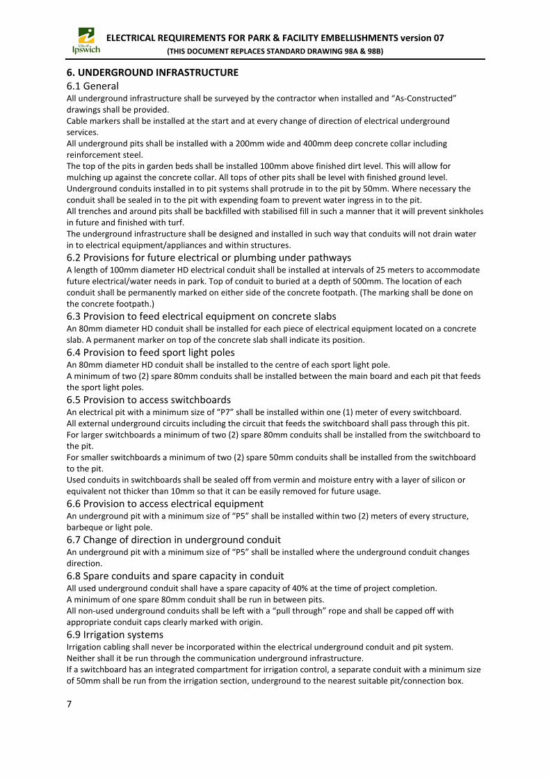
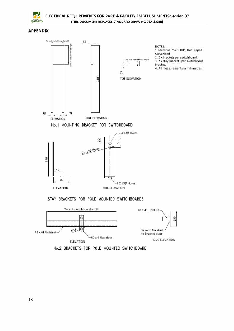
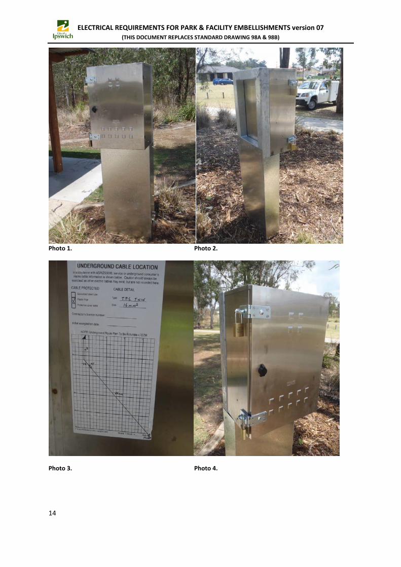
10.3 Sport lighting Cabling on top of the light poles shall be protected by “Flexicon” corrugated conduit with matching conduit fittings. LED luminaires and pole cross arms shall be installed with bird spikes in strategic locations to further prevent damage by birds and keeping the cooling elements of the luminaires clean of bird droppings and nests. Brand and type of bird spikes will need to be approved by Ipswich City Council. 10.3.1 Sport lighting type Sport lights shall have a low sail area and low glare design. Proposed light fitting (make, model, voltage system, etc.) will need to be approved by Ipswich City Council in writing. LED light fittings are now the preferred technology and conventional systems shall no longer be accepted in new installations or refurbishments. In existing conventional luminaire systems, the capacitors mounted on lighting control gear shall be facing up or down. This to ensure that if the top of the capacitor explodes the force is up/down the pole instead of towards the access hatch. 10.3.2 Sport lighting design LED lighting designs will need to be done to the appropriate standard. Lighting designs shall be signed off by RPEQ or full members of the Illuminating Engineering Society (MIES). All design drawings will need to be approved in writing by Ipswich City Council prior commencing of any work. It shall be noted that at the time of writing this document, Ipswich City Council are trialling new LED and software controlled technology for Sport field lighting. Advice should be sought from Council in regard to preferred circuit design, installation methods and equipment prior to commencement of any works. 10.3.3 Tree locations Trees that need planting in between light poles and the side of the sport field shall be given consideration in regards to their position and their physical size to prevent shade lines on the field during night usage. They shall also have appropriate distance from the light poles to prevent rubbing of branches against the light poles at the time of project delivery and years to follow after. Tree locations, species, sizes and general construction around tree zones shall be approved by the appropriate departments’ Council representative prior commencement of the project. 11. SWITCHBOARDS 11.1 General Long term growth planning for each site should be considered in regards to electrical load design for the switchboard(s). A spare physical capacity of at least 40% shall be kept at time of project delivery. This should prevent upgrading or replacing the switchboard in future. Switchboard designs shall be approved by the Council representative before start of any works. 11.2 Location of the switchboard Consideration should be given to the location of the switchboard. E.g. a switchboard feeding sport complex lighting should be located near the side of the field and closest to the main entry likely to be taken from the car park to the field. A switchboard feeding a barbeque, some park lights and a shelter should be located near the shelter where the sub circuits are likely to be of a shorter distance. If the switchboard is part of a project that includes the construction of a site building (e.g. clubhouse) then the switchboard should be located behind a lockable door that is part of the building structure. 11.3 Locking systems All locks shall be to Ipswich City Council standards. 11.4 Options As the size of electrical demand differs between projects, Ipswich City Council has a few options to be chosen from. 11.4.1 Option 1 (small installations) Switchboard shall be of stainless steel construction and mounted on mounting bracket as per Appendix drawing No.1 or No.2. (Depending on installation method) and installed as per Appendix photo No. 1, 2 and 3. Switchboard shall have two heavy duty hasp and staples fitted to the door mounted on the side of the board, top and bottom. As per Appendix photo 4.
11

ELECTRICAL REQUIREMENTS FOR PARK & FACILITY EMBELLISHMENTS version 07 (THIS DOCUMENT REPLACES STANDARD DRAWING 98A & 98B)
Switchboard shall have at least one 15 Amp din-rail mount socket outlet within the enclosure. The equipotential bonding of the switchboard shall not rely on earth bar/switchboard contact. As per Appendix photo 5. If the switchboard needs to be integrated with a Photo Electric cell, then it shall be mounted on the bottom of the switchboard. The PE cell shall be made by Royce Thompson model P12HE. Irrigation controllers shall have their own enclosure i.e. not to be located in distribution or metering areas of the switchboard. 11.4.2 Option 2 (larger installations) This switchboard shall be a free standing type, mounted on a low profile hot dip galvanise steel plinth on top of a concrete slab. (Concrete slab to suit weight loading and soil conditions) It shall be manufactured from heavy duty marine grade aluminium with a thickness no less than 3mm or 316 grade stainless steel with a thickness no less than 2mm. All compartments on the switchboard shall be installed with hinged doors with pad lockable handles. All escutcheon covers inside the board shall be steel and hinged type. If the switchboard should accommodate an irrigation section than it shall be designed in such a way that irrigation personnel shall never be exposed to live wiring. Please refer to Appendix photo 6 as an example. 11.4.2.1 Slab design The concrete slab shall surpass the outer measurements of the board by a minimum of 500mm. The concrete slab to surpass the front of the board by a minimum of 1500mm to provide a safe work environment for electricians working on the board in future. At the back of the board an electrical pit with a minimum size “P7” shall be integrated within the concrete slab. Minimum distance between the back of the board and the pit shall be 300mm. The top of the pit shall be level with the top of the concrete slab, pit lid included. This pit shall be installed in such a way that future access via extra underground conduits to this pit is guaranteed. The concrete slab shall surpass the outer side of the pit by a minimum of 300mm. No pit for irrigation shall be incorporated within the switchboard slab. For integration of the main earth electrode within the concrete slab, please refer the earthing section of this document. All necessary care shall be taken in stabilizing the soil prior installing the slab to guarantee prevention of slab sinkage. 11.5 Lighting over main switchboard If the main switchboard is externally mounted and fed via overhead cabling than the last power pole should be fitted with an outrigger and streetlight like fitting of a minimum of 35W LED that will illuminate over the top of the switchboard. The Mains feeding conduit on the pole shall not be combined with any other cabling of the installation. This light fitting shall be fed via a Photo Electric cell made by Royce Thompson model P12HE. The Photo Electric cell shall have a manual by-pass switch installed within the switchboard. Consideration should be given to the position of the PE cell so that no artificial light source shall influence the switching of the PE cell. No holes should be drilled through the timber pole for rear access for any light fittings. 11.6 Switchboard colours When a switchboard or control board is installed externally and exposed to the weather, generally the preferred colours shall be either: Stainless Steel, Aluminium, Crème or Mist Green. Any proposed colour, included the once mentioned above will need to be approved in writing by the Ipswich City Council representative. Darker colours should generally be avoided due to the absorbance of heat that may cause nuisance tripping of protective devices and overheating of electronic equipment within the board.
12
ELECTRICAL REQUIREMENTS FOR PARK & FACILITY EMBELLISHMENTS version 07 (THIS DOCUMENT REPLACES STANDARD DRAWING 98A & 98B)
APPENDIX
13
ELECTRICAL REQUIREMENTS FOR PARK & FACILITY EMBELLISHMENTS version 07 (THIS DOCUMENT REPLACES STANDARD DRAWING 98A & 98B)
Photo 1. Photo 2.
Photo 3. Photo 4.
14

ELECTRICAL REQUIREMENTS FOR PARK & FACILITY EMBELLISHMENTS version 07 (THIS DOCUMENT REPLACES STANDARD DRAWING 98A & 98B)
Photo 5. Photo 6.
15

ELECTRICAL REQUIREMENTS FOR PARK & FACILITY EMBELLISHMENTS version 07 (THIS DOCUMENT REPLACES STANDARD DRAWING 98A & 98B)
This page has been left intentionally blank.
16