Embed Size (px)
Citation preview

Electrical Performance of Fiberglass Crossarm in
Distribution and Transmission Lines
S. Grzybowski and T. Disyadej
High Voltage LaboratoryDepartment of Electrical and Computer Engineering
Mississippi State University
2008 IEEE PES T&D April 22, 2008, Chicago
2
Introduction• The materials used for crossarms in distribution and
transmission lines are steel, wood, and fiberglass.• Steel is always a conductor in any condition, so it does
not have an insulation resistance.• Wood has low electrical strength at AC especially under
wet condition, and also low mechanical strength per unit weight.
• Fiberglass has superior properties under dry condition compared to other materials.
• Its properties in non-conductivity and high mechanical strength-to-weight ratio make fiberglass crossarm supersede steel crossarm and wood crossarm.

3
Fiberglass Crossarms Installed on the Transmission Steel Tower
4
Electrical Strength of Three Different Types of Crossarms
Crossarm
Electrical Strength
AC Voltage CFO Voltage
Dry Wet Dry Wet
Steel Conduction Conduction Conduction Conduction
Wood Insulation Conduction Insulation Insulation
Fiberglass Insulation Conduction Insulation Insulation
5
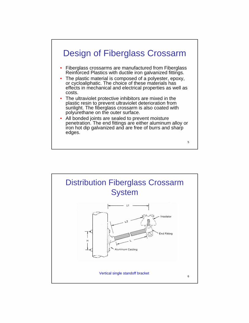
Design of Fiberglass Crossarm• Fiberglass crossarms are manufactured from Fiberglass
Reinforced Plastics with ductile iron galvanized fittings.• The plastic material is composed of a polyester, epoxy,
or cycloaliphatic. The choice of these materials has effects in mechanical and electrical properties as well as costs.
• The ultraviolet protective inhibitors are mixed in the plastic resin to prevent ultraviolet deterioration from sunlight. The fiberglass crossarm is also coated with polyurethane on the outer surface.
• All bonded joints are sealed to prevent moisture penetration. The end fittings are either aluminum alloy or iron hot dip galvanized and are free of burrs and sharp edges.
6
Distribution Fiberglass Crossarm System
Vertical single standoff bracket
7
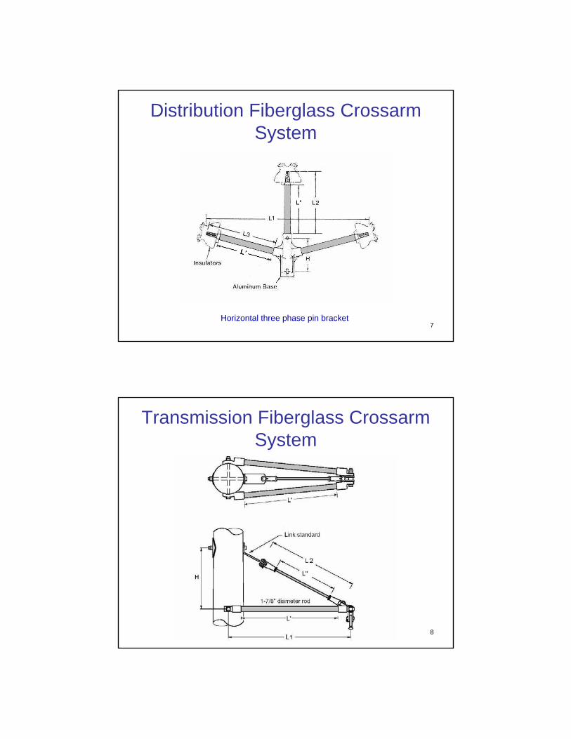
Distribution Fiberglass Crossarm System
Horizontal three phase pin bracket
8
Transmission Fiberglass Crossarm System

9
Damaged Surface of Fiberglass Crossarm after 20 Years in Service
10
Expected Lightning Impulse CFO and AC Flashover Voltages versusLengths for Fiberglass Crossarm
0
300
600
900
1200
1500
1800
0 1 2 3 4 5 6 7 8L [ft]
V[kV] Neg CFO, Dry
Pos CFO, Dry
AC, Dry
AC, Wet
11
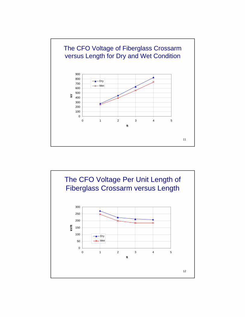
The CFO Voltage of Fiberglass Crossarm versus Length for Dry and Wet Condition
0100200300400500600700800900
0 1 2 3 4 5
ft
kV
Dry
Wet
12
The CFO Voltage Per Unit Length of Fiberglass Crossarm versus Length
0
50
100
150
200
250
300
0 1 2 3 4 5
ft
kV/ft
Dry
Wet

13
Flashover Arc on a Fiberglass Crossarm with Three Insulators
Lightning Impulse under Wet Condition
14
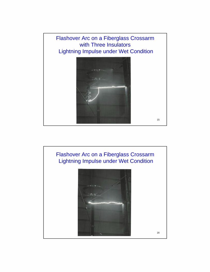
Flashover Arc on a Fiberglass Crossarm with Three Insulators
Lightning Impulse under Wet Condition
Flashover Arc on a Fiberglass Crossarm with Three Insulators
Lightning Impulse under Wet Condition
15
Flashover Arc on a Fiberglass Crossarm Lightning Impulse under Wet Condition
16

Flashover Arc on a Fiberglass Crossarm with Three Insulators
AC Voltage under Wet Condition
17
18
Flashover Arc on a Fiberglass Crossarm with Three Insulators
AC Voltage under Wet Condition

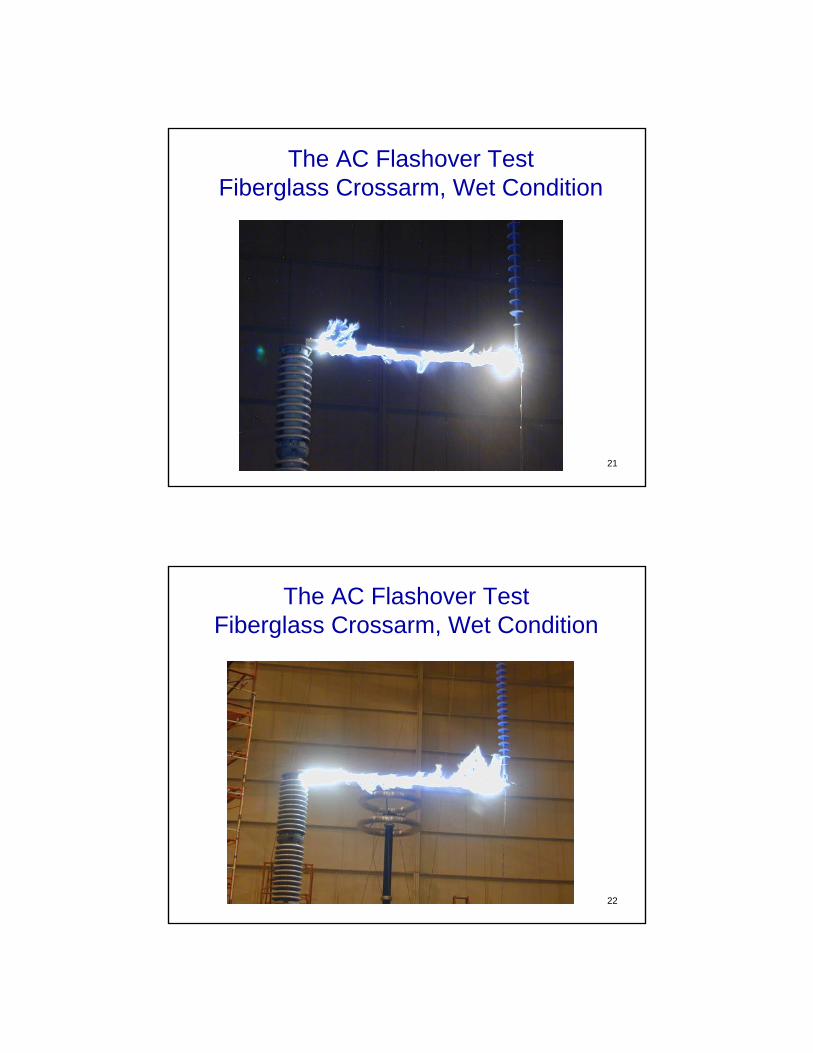
The AC Flashover Test Fiberglass Crossarm, Wet Condition
19
The AC Flashover Test Fiberglass Crossarm, Wet Condition
20
21
The AC Flashover Test Fiberglass Crossarm, Wet Condition
The AC Flashover Test Fiberglass Crossarm, Wet Condition
22

23
Fiberglass Crossarm Ends Damaged after AC Wet Test
If the leakage current level is high and time duration of applied voltage is long,
it could create extensive heat that would cause damage to the fiberglass crossarm surface.
240
300
600
900
1200
1500
1800
0 1 2 3 4 5 6 7 8L [ft]
V [kV]
Neg CFO, Dry
Pos CFO, Dry
AC, Dry
AC, Wet
Meas. Neg CFO, Dry
Meas. Pos CFO, Dry
Meas. AC, Dry
Meas. AC, Wet
Measured Lightning Impulse CFO AC Flashover Voltages versus
Lengths of Fiberglass Crossarm
25
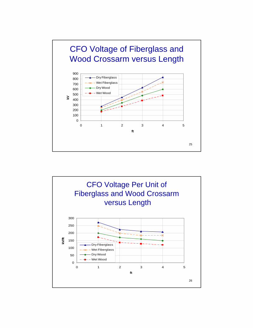
CFO Voltage of Fiberglass and Wood Crossarm versus Length
0100200300400500600700800900
0 1 2 3 4 5
ft
kV
Dry Fiberglass
Wet Fiberglass
Dry Wood
Wet Wood
26
CFO Voltage Per Unit of Fiberglass and Wood Crossarm
versus Length
0
50
100
150
200
250
300
0 1 2 3 4 5
ft
kV/ft
Dry Fiberglass
Wet FiberglassDry Wood
Wet Wood
27
Conclusions
• Taking all parameters into the account, especially the electrical performance, fiberglass crossarm can be used in place of other conventional crossarms.
• The fiberglass crossarm cannot be used as the only insulation component. It must be used as a secondary insulation component of the multiple-insulation with insulator as a primary insulation component.
28
Conclusions• For fiberglass crossarm with porcelain insulators,
CFO voltage is not much different under dry and wet condition.
• The AC flashover voltage under wet condition is approximately 50-60% lower than under dry condition.
• The CFO voltages of fiberglass crossarms are 30-40% higher than wood crossarms under dry condition and 40-50% higher under wet condition.
• As the length increases, the CFO voltage per unit length of the fiberglass crossarm and the wood crossarm tend to decrease.