Embed Size (px)
Citation preview

CougarTech Team 2228 Electrical Handbook
Revision V160401 Page 1 of 29
Electrical Handbook

CougarTech Team 2228 Electrical Handbook
Revision V160401 Page 2 of 29
Table of Contents
1 INTRODUCTION ................................................................................................................................ 6
1.1 Purpose ....................................................................................................................................... 6
1.2 Scope .......................................................................................................................................... 6
1.3 Audience ..................................................................................................................................... 6
1.4 References .................................................................................................................................. 6
1.5 Definitions ................................................................................................................................... 7
2 OVERVIEW ......................................................................................................................................... 7
2.1 Description .................................................................................................................................. 7
2.2 Electrical Modules ....................................................................................................................... 8
2.3 Electrical System Block Diagram................................................................................................ 9
2.4 FIRST Electrical Schematic ...................................................................................................... 10
3 ROBOT ELECTRICAL DETAILED DESIGN .................................................................................... 10
3.1 Overall Robot Design Process Steps ....................................................................................... 10
3.2 Robot Strategy .......................................................................................................................... 11
3.2.1 Team Development of Game Strategy ............................................................................... 11
3.3 Robot Design ............................................................................................................................ 11
3.3.1 Technical Team Robot Module Requirements ................................................................... 11
3.3.2 Technical Team Robot Concept Development .................................................................. 11
3.3.2.1 Control Interface Document(CID) ................................................................................ 11
3.4 Design Information Cascade .................................................................................................... 12
3.5 Electrical Robot Build Schedule ............................................................................................... 12
3.5.1 Week 1: ............................................................................................................................... 12
3.5.2 Week 2: ............................................................................................................................... 13
3.5.3 Week 3: ............................................................................................................................... 13
3.5.4 Week 4: ............................................................................................................................... 13
3.5.5 Week 5: ............................................................................................................................... 13
3.5.6 Week 6: ............................................................................................................................... 13
3.6 Concept and Preliminary Design .............................................................................................. 13
3.7 Detailed Electrical Design ......................................................................................................... 13
3.7.1 Electrical Design Documentation........................................................................................ 13
3.7.2 Schematic Diagrams ........................................................................................................... 15

CougarTech Team 2228 Electrical Handbook
Revision V160401 Page 3 of 29
3.7.2.1 Schematic Drawing Conventions ................................................................................ 15
3.7.2.2 I/O Schematic Diagram Example ................................................................................ 17
3.7.2.3 Electrical Schematic Program ..................................................................................... 17
3.7.2.4 Robot Schematics – Robot Wiring Sequence ............................................................. 18
3.8 Electrical Layout Best Practice ................................................................................................. 19
3.8.1 Typical Layout ..................................................................................................................... 19
3.8.2 Battery ................................................................................................................................. 19
3.8.2.1 Care of Batteries .......................................................................................................... 20
3.8.3 Main Breaker ....................................................................................................................... 20
3.8.4 Motor Drivers....................................................................................................................... 20
3.8.4.1 General Jaguar Precautions........................................................................................ 20
3.8.5 Wiring Layout ...................................................................................................................... 21
3.9 Robust Electrical Design- ......................................................................................................... 21
4 ELECTRICAL CRIMPING-TAPING-WIRING ................................................................................... 21
4.1 Crimping .................................................................................................................................... 21
4.2 Taping ....................................................................................................................................... 21
4.3 Wiring ........................................................................................................................................ 22
4.4 Electrical Assembly ................................................................................................................... 22
5 FRC TYPICAL WIRING RULES ....................................................................................................... 22
5.1 Wire Color Code ....................................................................................................................... 22
5.2 Power Wiring ............................................................................................................................. 22
5.3 Components .............................................................................................................................. 23
5.4 Fuses......................................................................................................................................... 23
5.5 Fuse Loads ............................................................................................................................... 23
6 ELECTRICAL TESTING - DEBUG ................................................................................................... 23
6.1 Electrical Testing Levels ........................................................................................................... 23
6.2 Safety: Power Up Verbal Verification Process: ........................................................................ 23
6.3 After Power Is Turned On ......................................................................................................... 24
6.4 Working On Electrical Equipment With Power On ................................................................... 24
7 TROUBLESHOOTING ...................................................................................................................... 24
7.1 Troubleshooting Process .......................................................................................................... 24
7.2 Device Troubleshooting Lights ................................................................................................. 24
7.3 Jaguar Motor Controller ............................................................................................................ 24
7.3.1 The LED status is as follows (not all conditions recreated here..) ..................................... 24
8 ROBOT ELECTRICAL TRAINING ................................................................................................... 25

CougarTech Team 2228 Electrical Handbook
Revision V160401 Page 4 of 29
8.1 Elect1 - Electrical Processes and Tools ................................................................................... 25
8.2 Elect1 - Electricity - Magnetics - Wire ....................................................................................... 25
8.3 Elect2 - FRC Control System Components .............................................................................. 25
8.4 Elect2 - Electrical Design - Layout - Wiring .............................................................................. 25
8.5 Elect2 - Troubleshooting ........................................................................................................... 25
8.6 Elect2 - Electronics - Drivers - Sensors .................................................................................... 26
8.7 Elect3- Motor Sizing .................................................................................................................. 26
8.8 Elect3- Electrical Magnetics(Solenoid/Motor/Motor Control) ................................................... 26
8.9 Elect3 - Printed Circuit Design(PCB) ........................................................................................ 26
8.10 Electrical Cross Training ........................................................................................................... 26
9 Appendix A: Electrical Pre-Assembly Checklist ............................................................................... 27
10 Appendix B: Electrical Assembly Test Checklist .............................................................................. 28
10.1 Visual Checks ........................................................................................................................... 28
10.2 Electrical Tests .......................................................................................................................... 28
11 Appendix C: Power UP Check List ................................................................................................... 29
11.1 Before Power is Applied – Visual inspection ............................................................................ 29
11.2 Before Power is Applied – Electrical Test ................................................................................ 29
11.3 Safety: Power Up Verbal Verification Process: ........................................................................ 29
11.4 After Power is Applied .............................................................................................................. 29

CougarTech Team 2228 Electrical Handbook
Revision V160401 Page 5 of 29
REVISION HISTORY
DATE DESCRIPTION OF CHANGE
V160401 RJV, revised with 2015-2016 Lessons learned
V151223 RJV, revised detail design process, add ICD document
V151107 RJV, updated information flow, TOC, web based schematic programs, design process
V150406 RJV, updated design process
V150302 Original

CougarTech Team 2228 Electrical Handbook
Revision V160401 Page 6 of 29
1 INTRODUCTION
1.1 Purpose The purpose of this handbook is to provide electrical best practices in design, fabrication, testing, and troubleshooting. The handbook also provides index to electrical documentation, electrical training, electrical tips and reference material.
1.2 Scope The scope of this document is to provide a best practice handbook for the electrical sub-team.
1.3 Audience The audience for this document is the CougarTech Robotics technical team.
1.4 References Information in this handbook and in the training were leveraged from the experience of FIRST Teams and general electrical theory. First 2007 Guidelines,Tips, & Good Practices 2005CON Electrical Design Team111 2006CON Electrical Design Team2018,Team71 2009 Advanced robot electrical design and technique team111 Team358 electrical workshop 2010 Introductory Circuit Analysis Robert L. Boylestad : Chapter 4 – Ohm’s Law, Power and Energy CPO Science Foundations of Physics unit7 chapter 19 Electrical Systems 101 Team 2377 Electronics Workshop Team604 Mentor workshop - Electrical sub-system Team358 FIRST Wiring the FRC 2015 Control System Electronic Best Practices Team2641 RoboJackets: Session5: Robot Electronics Team995 - Electric Team Certification Team 358 Hauppauge High School Electrical Workshop 2010

CougarTech Team 2228 Electrical Handbook
Revision V160401 Page 7 of 29
Team148 2015 Control System Beta 10-18-14
1.5 Definitions BOM Bill Of Materials CAN Controller Area Network CID Control Interface Document ESC Electronic Speed Control PCM Pneumatics Control Module PDP Power Distribution Panel PPD Pulse Position Modulation PWM Pulse Width Modulation SPI Serial Peripheral Interface USB Universal Serial Bus VRM Voltage Regulator Module
2 OVERVIEW
2.1 Description FIRST constrains the design of the electrical system by specifying the electrical components that FIRST teams can use. This puts all teams on the same level of control. This handbook provides a best practice reference for the electrical design process and use of electrical components.

CougarTech Team 2228 Electrical Handbook
Revision V160401 Page 8 of 29
2.2 Electrical Modules
Power System
(Battery/Power Switch/Power Distribution Panel(PDP)/Volt Reg Modue(VRM)/Pneumatics Cntrl
Module(CPM))
Controller
(RoboRio)
Sensors
(Optical/Magnetic/Switch/
Potentiometer)
Actuators
(Motor Drive/Solenoids)
Input
(Analog/Digital)
Output
(Digital/PWM)
Communications
(Ethernet/USB/SPI/CAN)
Devices
(Camera/Gyro/
Motor Drive/Pneumatics Control
Module(PCM))
There are three electrical module levels to the robot:
1) Power System: Battery, Power switch, power distribution, and voltage regulation 2) Controller: RoboRio 3) I/O: sensors, actuators and devices

CougarTech Team 2228 Electrical Handbook
Revision V160401 Page 9 of 29
2.3 Electrical System Block Diagram
PCM
(Pneumatics Control
Module)
Motor Drivers
(Jaguar/Talon/SP/SRX)
PDP
(Power Distribution Panel)
VRM
(Voltage Regulator
Module)
Battery
/Pwr Switch
Power Management
Supervisory Control
(Software-JAVA)
Input/Output[I/O]
(Analog/Digital)
Speed Control
(PWM)
Communications
(Ethernet/CAN/USB/SPI)
RoboRio
CAN
Ethernet
Modem
“Bridge”
CAN
+5V +12V
USBSwitch
ESC
[Electronic Speed Controller]
There are three main sections in the design of the robot electrical System;
1. Power Management: This includes the Battery/Main Robot power switch, Power Distribution Panel(PDP) and the Voltage Regular Module(VRM)
2. Pneumatics Control: This includes the Pneumatics Control Module(PCM) 3. Robot Controller: This includes the RoboRio and RF Modem(Bridge)

CougarTech Team 2228 Electrical Handbook
Revision V160401 Page 10 of 29
2.4 FIRST Electrical Schematic
3 ROBOT ELECTRICAL DETAILED DESIGN
3.1 Overall Robot Design Process Steps
Game
Description
Game
Analysis
Functional
Requirements
Concept /
Prototype
Detailed
Design
Fabrication /
Assembly / Test
Robot
Competition
Robot Strategy Robot Design Robot Build Robot Eval
Prototype Evaluation / Improvement

CougarTech Team 2228 Electrical Handbook
Revision V160401 Page 11 of 29
3.2 Robot Strategy
3.2.1 Team Development of Game Strategy After the kickoff video and READING the game manual, the team will develop the following:
1. A game strategy that includes how the robot will move on the playing field and what
actions the robot has to do to play the game.
2. The team will also define the constraints of the robot from the Game Manual.
3.3 Robot Design
3.3.1 Technical Team Robot Module Requirements The technical team(Mechanical/Electrical/Software) will group the robot actions developed by the team with respect to the basic robot module model shown below. The robot constraints listed by the team will also be grouped with respect to the robot model.
3.3.2 Technical Team Robot Concept Development During the robot concept development the electrical team is responsible for developing the sensor input and actuator output list for the robot mechanism concepts.
3.3.2.1 Control Interface Document(CID) The control devices are documented in the Control Interface Document(CID). The CID is typically an Excel table that has the following columns:
1) Item Number 2) Module Name: (e.g. lift) 3) I/O device name (e.g. lift Motor) 4) I/O device type: (e.g. switch, motor, solenoid, encoder, ultrasonic, optical switch) 5) Device ID: (e.g. M1, SW3, ENC1, US1, SOL1) 6) Controller ID: (e.g. PWM0, K3, 7) Cable ID: From Tag - To Tag: (e.g. PWM1 - M3)
The software team is responsible for understanding how the robot will function.

CougarTech Team 2228 Electrical Handbook
Revision V160401 Page 12 of 29
3.4 Design Information Cascade The general flow of a robot design has a cascade effect on when technical disciplines engage in the design and fabrication process. The cascade effect is shown in the following diagram.
Robot Functions Definition
Robot FIRST Constraints Definition
Mechanical Concept:
1) Robot Specification
a) Module definition
b) Module constraints
c) Module functionality definition
Electrical Prelim Design (Analysis):
1) Prelim module control system concept: sketches
2) Control Interface Document(CID): Module Sensors/Actuators definition
3) Prelim BOM: Basic control system, sensors, actuators
4) Order Parts: Review Team electrical inventory, order components that are
not on hand
FRC Standards: Power System,
Control components, Pneumatic &
Communications Design
Electrical Detailed Design:
1) Electrical Schematics:
a) Power schematic
b) Network/CAN schematic
c) RoboRio schematic: I/O wiring
c) Pneumatic schematic
2) Electrical Layout Diagram
3) Electrical Wiring Routing Diagram
4) Final Electrical BOM, electrical component weight
Robot Strategy
Software
1)Class Model: Class definitions, Class methods
2) RoboMap.java I/O definition from CID document
Electrical Fabricate / Assemble
1) Fabricate electrical panels
2) Assemble control system
Electrical Test / Debug
1) Power up check / Power up
2) Software I/O check
Team 2228 Standards:
Electrical Handbook
3.5 Electrical Robot Build Schedule
3.5.1 Week 1: 1. Support concept and prototype development

CougarTech Team 2228 Electrical Handbook
Revision V160401 Page 13 of 29
2. Develop first cut of CID document: Robot mechanical modules, control components(sensors, motors, etc)
3. Develop first cut electrical layout 4. Develop power schematic and start the electrical BOM
3.5.2 Week 2: 1. Develop electrical architecture – matching I/O to control components 2. Develop electrical layout 3. Develop first cut electrical I/O schematics and update electrical BOM 4. Order parts needed
3.5.3 Week 3: 1. Complete schematics and BOM 2. Complete panel layout 3. Kit control system parts 4. Test functionality of parts where possible 5. Image RoboRio, update firmware on motor controllers, set CAN addresses 6. Update CID document with firmware version, CAN addresses 7. Complete pre assembly checklist
3.5.4 Week 4: 1. Build electrical control panels.
3.5.5 Week 5: 1. Install electrical panels 2. Wire sensors and motors 3. Complete assembly check list 4. Complete power up check list
3.5.6 Week 6: 1. Support robot during driver testing and robot evaluation
3.6 Concept and Preliminary Design During the Concept and Preliminary Design process The following items should be considered:
1. The electrical system should be considered early in the design. It should not be an afterthought that there will be the correct space for the electrical system.
2. The electrical sub-team needs to work with the mechanical and software sub-teams to understand the robot functions and control concepts to develop the electrical system.
3. By the end of the concept and preliminary design phase of the robot design, a preliminary layout, electrical schematic, and BOM should be developed. New parts should be ordered.
3.7 Detailed Electrical Design
3.7.1 Electrical Design Documentation In designing the electrical system the following documentation should be developed:
1) Electrical schematics should be developed.
2) Electrical layout drawings. This would include electrical panel layout, cable/cable tag
layout between I/O devices and control modules(noting control module ID’s)
3) Electrical “Control Interface Document” (CID)

CougarTech Team 2228 Electrical Handbook
Revision V160401 Page 14 of 29
a. The CID document is typically a spread sheet that names all the sensors and
motors by module with names agreed on by the team.
b. The CID should be formatted as a table for sorting purposes
c. Device naming convention: Module-Module function-electrical device name
(e.g. Shooter-Elevator-Motor; [software will have a corresponding name e.g.
shooterElevatorMotor)
d. Example of a CID document:
4) Team BOM (Bill of materials) is an spread sheet which includes the following items:
a. Quantity
b. Component name
c. Component description
d. Component part number
e. Supplier
f. Supplier part number
g. Web address of supplier
h. Weight
i. Cost.
5) Robot BOM – BOM for robot competition which includes the following items:
a. Item: supplier part number
b. Description: description of electrical component
c. Material: (Not used)
d. Source: Name of supplier
MODULE
DEVICE NAME
(Directory Style:
Module-Function-DeviceClass) DEVICE CLASS DEVICE ID
CAN
ID
DEVICE
NAME
GEAR
STYLE
GEAR
RATIO
ENCODER
STYLE
ENCODER
CNTS/REV
RoboRio
CONNECTION
PDP
CONNECTION
PDP
FUSE VALUE REMARKS2
Controls Cntrl-RoboRio Controls CNTRL1 RoboRio RoboRio 10A
Controls PwrDist(PDP) Controls PDP 00 PDP
Controls VltReg(VRM) Controls VRM VRM VRM 20A
Controls Communication Bridge Controls BRDG BRIDGE Pwr from VRM
Controls Battery Battery BAT BAT
Controls Power Switch Switch PWRSW PWR SWITCH
Controls Drive Team Camera Camera CAM1 USB Camera Pwr from VRM
Drive Train DrvTrn-Left motor1 Motor DTLM1 CIM
Drive Train DrvTrn-Left MC1 Motor Controller DTLMC1 01 Talon SRX Channel 0 40A Ch0-3, 12-15: 40A
Drive Train DrvTrn-Left motor2 Motor DTLM2 CIM
Drive Train DrvTrn-Left-MC2 Motor Controller DTLMC2 02 Talon SRX Channel 1 40A
Drive Train DrvTrn-Left-Encoder Encoder DTLENC CIMCoder Mag Encoder 20
Drive Train DrvTrn-Lft-Gear box Gear Box DTLGB Spur 11:1
Drive Train DrvTrn-Rgt-motor1 Motor DTRM1 CIM
Drive Train DrvTrn-Rgt-MC1 Motor Controller DTRMC2 03 Talon SRX Channel 2 40A
Drive Train DrvTrn-Rgt-Motor2 Motor DTRM2 CIM
Drive Train DrvTrn-Rgt-MC2 Motor Controller DTRMC2 04 Talon SRX Channel 3 40A
Drive Train DrvTrn-Rgt-Gear box Gear Box DTRGB Spur 11:1
Drive Train DrvTrn-Rgt-Encoder Encoder DTRENC CIMCoder Mag Encoder 20
Gatherer Gatherer-Spinner-Motor Motor-Gear GTSPM RS-550 Planetary 16:1
Gatherer Gatherer-Spinner-MC Motor Controller GTSPMC Talon SP Channel 4 30A
Gatherer Gatherer-Lifter-Motor Motor-Gear-Enc GTLFTENC RS-550 Planetary 17:1 CTR Mag Enc 1024
Gatherer Gatherer-Lifter-MC Motor Controller GTLFTMC 05 Talon SRX Channel 5 30A
Gatherer Gatherer-Lifter-Dwn Lim Switch GTLFTDWNLS Limit Switch
Shooter shooter-Left Wheel-Motor Motor-Gear-Enc SHLWHLM RS-550 Planetary 5.4:1 CTR Mag Enc 1024
Shooter Shooter-Left Wheel-MC Motor Controller SHLWHLMC 06 Talon SRX Channel 8 30A
Shooter Shooter-Right-Wheel Motor-Gear-Enc SHRWHLM RS-550 Planetary 5.4:1 CTR Mag Enc 1024
Shooter Shooter-Right Wheel-MC Motor Controller SHRWHLMC 07 Talon SRX Channel 9 30A
Shooter Shooter-Elevator-Motor Motor-Gear-Enc SHELVM RS-550 Planetary 171:1 CTR Mag Enc 1024
Shooter Shooter-Elevator-MC Motor Controller SHELVMC 08 Talon SRX Channel 10 30A
Shooter Shooter-Elv Dwn-Lim Switch Switch SHELVDWNLS Limit Switch
Shooter Shooter-Bld Present-Sensor Sensor SHBLDSEN PhotoElectric Digital0
Shooter Shooter-Bld Advance-Servo Motor SHBLDADVM Servo PWM0
CougarTech Team 2228 Electrical Handbook
Revision V160401 Page 15 of 29
e. Quantity: how many
f. Measure: “Piece”
g. Unit Price: in dollars
Note: A core BOM that has the basic control components should be available before
build season.
3.7.2 Schematic Diagrams A schematic diagram is a documentation on how the electrical system is wired. There are three types of schematics:
1) Wiring - A diagram showing how electrical sub-system components are wired. Electrical sub-system components are typically shown as boxes.
2) Electronic - A wiring diagram of electronic components on a printed circuit board. There are a variety of symbols depicting electronic components.
3) Electrical Layout and cable routing - A diagram showing the physical placement of electrical sub-system components and how wiring will be routed. This can be done in CAD to check for mechanical inferences.
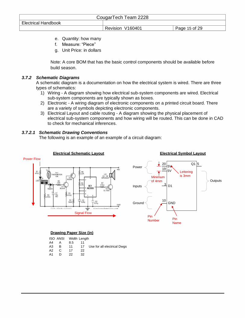
3.7.2.1 Schematic Drawing Conventions The following is an example of an example of a circuit diagram:
Power Flow
Signal Flow
Electrical Schematic Layout Electrical Symbol Layout
Outputs
Power
Inputs
Ground
Q15V
5
5V
GND
20
10
19
Pin
Number Pin
Name
Drawing Paper Size (in)
ISO ANSI Width Length
A4 A 8.5 11
A3 B 11 17 Use for all electrical Dwgs
A2 C 17 22
A1 D 22 32
Lettering
is 3mmMinimum
of 4mm
D13

CougarTech Team 2228 Electrical Handbook
Revision V160401 Page 16 of 29
The following is an example of an electrical ladder diagram. This circuit layout is typically used for relay circuits and for I/O interface diagrams:
Sequence Flow
Electrical Ladder Diagram Layout
Power Flow, Signal Flow, Input-to-Output Flow
Ladder rungs
Typical circuit diagram conventions are as follows:
1) Logic flow should be from left to right 2) Inputs to sub-system components should be shown on the left side of the box 3) Output of sub-system components should be shown on the left side of the box 4) Power should be shown on the top of the box or top of the left side and common or
ground should be shown on the bottom of the box or the bottom of the left side. 5) Controller nomenclature: PDP, RoboRio, PCM, VRM 6) Controller I/O nomenclature: PWM(0-9), Relay(0-3), DIO(0-9), AI(0-1); PDP(0-15);
PCM(0-7) 7) I/O Device nomenclature: Relay[Spike](K), Solenoid(SOL), Encoder(ENC), Ultrasonic
sensor(US), limit switch(SW), optical sensor(PE), motors[DC/Servo](M), Resistors(R), Camera(CAM)
8) Cable Labeling is as following: tag wire ties should be attached at each end of a cable. The tag should be labeled noting what device the wires came from.

CougarTech Team 2228 Electrical Handbook
Revision V160401 Page 17 of 29
3.7.2.2 I/O Schematic Diagram Example Typical motor controller schematic layout and wiring with a Talon SRX motor controller:
>
>
MC2
M2
wht
Grn
M2 MC2
Blk
Red
Talon SRXPDP0
H
HL
L
H
HL
L
GrnYel
GrnYel
RioCAN
Yel
Yel
Grn
Grn
TB1
TB2
MC3<<
<<Lim Fwd
<<
<<Lim Rev
<<+
<<S
<<G
Analog
>>
<<B
<<+
<<A
<<Index
<<G
Encoder
TSUB2
NCFL2TSUB2FL2
NC
RL2
TSUB2RL2
ENC2
ENC2TSUB2
Cable Tags
Signal Flow; Input-to-output
Pinsocket
Normally: Power is on Sockets
Add wire color
“Symbol layout
looks like part
layout”
Where wires
came from
Power Flow; Sequence Flow
1024 CPR
Add tech info
CIM
Signal (Wht or other color)
Gnd (Blk)Power (Red)
Std 3 pin wiringPin 1 mark on
connector
Plug in PCB board
3.7.2.3 Electrical Schematic Program TinyCAD will be used as the electrical schematic / wiring layout drawing CAD package. TinyCAD is on the school computers. Set the options up to measure in mm and the paper size should be A3. When printed on 8.5x11 paper the diagram is still readable. To make a new symbol:

CougarTech Team 2228 Electrical Handbook
Revision V160401 Page 18 of 29
1. Click on the Open the Libraries button 2. Select Team2228 library and then select edit library 3. Right click on library and select new symbol
The text in symbols are 3mm high. Thus the minimum distance for pins should be 4mm.
3.7.2.4 Robot Schematics – Robot Wiring Sequence There should be Five Electrical Schematic diagrams for a robot.
1. Electrical Panel Layout with ID tags noted 2. Electrical Wiring Layout showing all I/O devices and cable tags 3. Power Wiring Diagram – this schematic details how power is wired on the robot. 4. Input / Output wiring diagram – this schematic details how all the robot electrical input –
output devices are wired 5. Communications Wiring Diagram – this schematic details how to wire all communications
connections (e.g Ethernet, CAN, USB, SPI, SP).
To reduce wiring errors, the robot should be wired in the same sequence noted (e.g. Power, I/O, Communications).

CougarTech Team 2228 Electrical Handbook
Revision V160401 Page 19 of 29
3.8 Electrical Layout Best Practice The following items should be considered in the layout of the electrical system:
3.8.1 Typical Layout This is a typical layout(From Team148). The important items to note are the layout of the power components(i.e. The power switch, power distribution, and the motor speed controllers). The goal is to mount components in practical locations for short wire runs and easy access.
3.8.2 Battery 1. Secure the battery so it doesn't fall out 2. Main battery, low and near the center of robot or as counter weight for another robot
system.

CougarTech Team 2228 Electrical Handbook
Revision V160401 Page 20 of 29
3. Mount so that it will not move when the robot is struck 4. Mount so that it will not contact metal parts when installed or removed 5. Use a removable belt, strap or clamp to fix in place 6. Battery should be mounted securely and is readily removable(During competition, there is
often very little time between matches).
3.8.2.1 Care of Batteries 1. Don't drop batteries 2. Don't pick up batteries by terminals or attached wires 3. Store away from heat 4. Periodically top off charge during the offseason 5. Make sure to always have extra batteries charged 6. A fully charged battery should be used in each match
3.8.3 Main Breaker The following items should be considered in the layout of the electrical system:
1. Position the breaker so it is easy to get at from outside the robot 2. Mount breaker on a flat surface so that the body of the breaker cannot be stressed or
cracked. 3. Mount where the breaker will complete the shortest run from battery disconnect to first
distribution block. 4. Mount so that mechanical systems cannot move against the terminals and other robots
cannot push the reset button
3.8.4 Motor Drivers 1. The design of the electrical panels should be design such that they can be accessed for
repair or testing.
2. The motor power leads should be short(close to the PDP)
3. The panels should be assembled with electrical components and fitted on the robot to test
for any interferences.
4. The wiring should not be a rats nest. Control wiring(low voltage) should be routed together
separate from motor wiring. (This is done to prevent electrical noise from coupling into low
level sensor circuits.)
5. All cables should be labeled.
6. The CAN communications wires should be twisted pair wires. (This is done to prevent
electrical noise from coupling into low level sensor circuits.)
7. Color code should be consistent throughout the robot
3.8.4.1 General Jaguar Precautions
1. Mount the Jaguar module so that the vents in the top and sides of the unit are not
restricted in any way. Maintain a clearance of at least ½ inch between modules.
2. Do not exceed the absolute maximum supply. Doing so causes permanent damage to the module
3. Protect Jaguar from all situations where debris could enter through ventilation slots
or connector openings.

CougarTech Team 2228 Electrical Handbook
Revision V160401 Page 21 of 29
3.8.5 Wiring Layout 1. All wiring should be laid out in a logical, orderly manner between circuit devices 2. KEEP WIRING NEAT: Wires should be routed and extra length wrapped in a loop and wire
tied in two places. 3. Keep wiring out of the way of moving components 4. Use wire ties to tie down wiring. 5. Make sure to label all wiring so that if components need to be replaced 6. Use labeling system to associate wires with functions. 7. Reduce wiring - Make sure to use as little as needed. Inspectors can readily see what you
have, and will be able to check things much faster 8. Choose a safe and protected pathway inboard the main robot frame for the
harness to ensure the robustness and reliability of the electrical system 9. Whenever possible, harnesses should be sorted and separated into “power” and “Signal”
cable groups. Ideally they should be run in different pathways to their destinations. If signal wires have to cross over power wires, the signal wires should be perpendicular to the power wires.
3.9 Robust Electrical Design- The following items should be considered in the design of a robust electrical design:
1. Metal Filings – are bad, bad, bad for electronics; remove or cover all electronics before any filing, drilling, sawing, etc
2. Liquids – keep these away, don’t tempt fate 3. Allow for airflow (cooling) 4. Vibration – mount electronics so they don't get mechanically shocked, vibrated, shaken
to death, crushed, collided, or otherwise mutilated 5. Location of the Terminal Blocks to minimize wire length and allow easy connection of 40
amp returns 6. Control System status lights and buttons visible and accessible 7. Keep ports on robot controller clear 8. Neatness counts – tie-up cable runs 9. Access to all components for test and replacement 10. Reduce resistance in the electrical design. This is accomplished by short power wire
runs, good crimps(high current should be soldered)
4 ELECTRICAL CRIMPING-TAPING-WIRING
4.1 Crimping 1. Be sure of crimp on connectors by using a ratchet style crimper. Use the proper terminal
size and proper length of stripped area. 2. Solder terminals when you doubt the effectiveness of the crimp 3. Solder critical terminals (like the 6 AWG battery lugs) 4. Insulate exposed electrical terminations
4.2 Taping 1. To make taping easy to remove, the following process should be used:
a. After you cut a piece of tape, bend over both end of the tape to form two end tabs b. Wrap the tape around the components being taped c. To remove the tape, pull on the outside tab to separate the tape

CougarTech Team 2228 Electrical Handbook
Revision V160401 Page 22 of 29
4.3 Wiring 1. Use appropriate gauge wire. Inspectors will be checking this closely 2. Leave some slack in wire to allow for swapping of parts 3. Wires leaving devices should be grouped and bound together with plastic ties and chassis
anchors to form wire harnesses 4. Consider weight of wire - short wire runs 5. Secure wire so a hit from another robot doesn't stretch, pull or break the wiring from robot
devices 6. Run wiring through frame members such that mechanicals don't drill into it 7. Make sure all connections are insulated. Use insulated connectors, electrical tape, or
adequate heat shrink for all connections.
4.4 Electrical Assembly 1. Before assembling any electrical subsystem all parts should be gathered into a kit 2. The pre-assembly check list should be completed 3. After assembly the assembly check list should be completed 4. Before power up the power up check list should be completed
5 FRC TYPICAL WIRING RULES
Every year the Robot manual should be reviewed for electrical requirements by FIRST. Also the Inspection sheet should be reviewed(2015 - CTElect-.First 2015-FRC-Inspection-Checklist)
5.1 Wire Color Code Power:
RED: +12 volts RED/BROWN: +5 BLACK: +12 Volt Power return line BLACK/BLUE: +5 Volt Return
CAN wires:
YELLOW, GREEN twisted Signal wires:
WHITE: Signal line BLACK/GREEN: Signal return line
5.2 Power Wiring 1. Keep wire runs short, especially those that share currents 2. Use #6 wire or larger for primary loop 3. Crimp and solder heavy ring terminals for screw terminations Consists of #6 wiring, 50 amp
Anderson connector, Main breaker, Power Distribution Panel and battery 4. Use lock washers between the battery terminals and the wire terminals to prevent terminals
from twisting and causing loose hardware 5. Frame must be electrically isolated from battery(>10k Ohm between either PD battery post
and chassis) 6. #10 for high current loads(i.e. main motors)

CougarTech Team 2228 Electrical Handbook
Revision V160401 Page 23 of 29
5.3 Components 1. Spike must have 20 amp fuse installed 2. Only one motor or load may be attached to each Spike, Jaguar Talon SRX 3. (however two pneumatic valves may be driven by a single Spike). 4. Motor/Actuator Power –CIM and FP motors must be fed by speed controllers 5. Motors can only be driven directly by PWM signals from a RoboRIO or by CAN bus 6. Only one wire per weldmuller connection
5.4 Fuses 1. Only 20, 30 and 40 Amp Snap-Action breakers may be installed in the PDP 2. Wire / Fuse conventions:
a. 40 amp breakers have min #12 AWG b. 30 amp breakers have min #14 AWG c. 20 amp breakers have min #18 AWG
5.5 Fuse Loads 1. Each speed controller must be
6 ELECTRICAL TESTING - DEBUG
STOP-STOP-STOP-STOP-STOP-STOP- STOP-STOP-STOP-STOP-STOP-STOP
6.1 Electrical Testing Levels There are four levels of electrical testing:
1. Pre-assembly testing; see pre-assembly check list in appendix 2. Assembly testing; see assembly check list in appendix 3. Power up testing; see power up check list in appendix 4. Debugging
6.2 Safety: Power Up Verbal Verification Process: 1. A safety observer shall be assigned. 2. The person on the “Power Switch” Shall proclaims “Power ON” 3. Only the safety observer after assessing the situation responses “All Clear”

CougarTech Team 2228 Electrical Handbook
Revision V160401 Page 24 of 29
4. The person on the “Power Switch” final response should be “Power Active” (This response is a verification of the safety observer.)
6.3 After Power Is Turned On 1. After power is turned on check the status of all troubleshooting LED's 2. With the RoboRio powered up and the driver station powered up, use the I/O test screen
to check all I/O
6.4 Working On Electrical Equipment With Power On 1. Shut the Power OFF before working on electrical circuits or exchanging components. Also
vent the pneumatic system. 2. Following electrical service work always inspect potential short circuits before applying
power
7 TROUBLESHOOTING
7.1 Troubleshooting Process When troubleshooting the following items should be checked:
1. Is everything plugged in? 2. Is there power? 3. Are all connections secured? 4. Are there any loose or broken wires? 5. Is there any debris shorting something out? 6. What do the troubleshooting lights say? 7. If the system was working, what has changed?
Remember people skills are important, everyone has a suggestion on how to fix the problem or who is to blame. You may have to "fix the customer" before you fix the equipment. Here is where Gracious Professionalism comes into play.
7.2 Device Troubleshooting Lights See CTElect-FIRST Status LED Troubleshooting. This document covers:
o Robot Signal Light o RoboRIO o Power Distribution Panel o Voltage Regulator Module o Pneumatics Control Module o Jaguar speed Controller o Talon-SPX speed Controller o Spike Relay
7.3 Jaguar Motor Controller
7.3.1 The LED status is as follows (not all conditions recreated here..)
1. Fast flashing yellow means you're NOT getting a valid signal on the wire. If you've got this, check your code or your wiring.
2. Solid yellow means you're getting a valid signal on the wire and that it is in the
neutral range, and should produce 0 V on the output.
CougarTech Team 2228 Electrical Handbook
Revision V160401 Page 25 of 29
3. Fast flashing green means that you are going forward, and should produce between 0
V and 12 V.
4. Solid green means that you're at full forward, and should produce 12 V on the output. 5. Fast flashing red means that you are going reverse, and should produce between 0
V and -12 V.
6. Solid red means that you're at full reverse, and should produce -12 V on the output. 7. Output voltage measured across M+ and M- (white terminal to green). 8. Also, check your limit switch jumpers are both installed
8 ROBOT ELECTRICAL TRAINING
8.1 Elect1 - Electrical Processes and Tools Topics:
1. How to crimp a terminal 2. How to solder 3. How to splice an inline wire 4. How to solder a component to a printed circuit board 5. How to de-solder a component from a printed circuit board
8.2 Elect1 - Electricity - Magnetics - Wire Topics:
1. Electricity - Mechanical Analogy 2. Basic components: Battery, Resistance 3. Electrical relationships(E=IR...) 4. Wire Characteristics 5. Magnetics in action(Relay, Solenoid, Motor)
8.3 Elect2 - FRC Control System Components Topics:
1. 2015-2019 Control System Components 2. Sensor overview
8.4 Elect2 - Electrical Design - Layout - Wiring Topics:
1. FRC Wiring Architecture 2. Electrical Schematics / BOM 3. Electrical Layout 4. Wiring Control System Components 5. Wire routing 6. Competition Electrical Inspection 7. Fail Safe Wiring 8. Robust electrical design
8.5 Elect2 - Troubleshooting Topics:
1. Electrical Power up process 2. Component LED status lights 3. Driver Station I/O checkout

CougarTech Team 2228 Electrical Handbook
Revision V160401 Page 26 of 29
4. Electrical Measurements
8.6 Elect2 - Electronics - Drivers - Sensors Topics:
1. Signals: analog / Digital 2. Transistors - Integrated circuits 3. Drivers: Output Driver, Solenoid driver, motor driver 4. Sensors: Switches, Encoders, Ultrasonic's, Optical, LIDAR, accelerometers, gyro, Vision
8.7 Elect3- Motor Sizing Topics:
1. Motor equations 2. Motor curves 3. Mechanical advantage: gears 4. Motor sizing
8.8 Elect3- Electrical Magnetics(Solenoid/Motor/Motor Control) Topics:
1. Magnetics(Magnetics at work: solenoid, motor) 2. Motor control components - architecture 3. Motor operational theory 4. Motor driver theory(PPM, PWM, H-Bridge) 5. Motor Feedback: analog - Digital(encoder)
8.9 Elect3 - Printed Circuit Design(PCB) Topics:
1. Bread Board Design 2. Schematic Capture 3. PCB CAD tools 4. PCB Etching
8.10 Electrical Cross Training It is the expectation that the electrical sub-team members have cross training in mechanical and software topics. See Technical Director handbook on training matrix.

CougarTech Team 2228 Electrical Handbook
Revision V160401 Page 27 of 29
9 Appendix A: Electrical Pre-Assembly Checklist
Are the Electrical schematics completed?
Are signal levels between devices correct?
Is the Electrical Bill of Materials completed?
Has the electrical system weight been determined?
Has the control system kit of parts completed?
Has the RoboRio been imaged?
Have the Motor controllers configured and firmware updated?
Have the motor controllers been configured with CAN bus addresses?
Has the CID documented updated with motor controller firmware version?
Have motors been evaluated? (i.e. Motor resistance and quick 12volt operational test)
Have sensors been tested for operation?
Are all components labeled with ID tags with respect to CID?
Are component cables labeled with ID tags with respect to CID?

CougarTech Team 2228 Electrical Handbook
Revision V160401 Page 28 of 29
10 Appendix B: Electrical Assembly Test Checklist
10.1 Visual Checks
Open the Main Circuit Breaker with the RESET button and/or unplug the battery
Check all connections. Check for any wires that may be shorted or frayed wires
Check for broken wires
Check that there is no debris shorting something out
Inspect battery for cracked, or damaged battery cases, or any evidence of electrolyte leakage
Check for polarity wiring on all modules, speed controllers (Talon SRX, Jaguar)
Check CAN wiring. Is the PDP the last module in the network chain?
10.2 Electrical Tests
With a multi-meter measure the resistance on the circuit side of the power switch that there are no shorts.
Check CAN resistance: Measure with an ohm meter across the GREEN and YELLOW wire. The meter should be about 60 ohms. (The bus has two 120 ohm terminating resistors, one at each end)
With electrical test box test the cabling, function of all sensors, and encoders.
Mark off on CID document sensors and motors tested.

CougarTech Team 2228 Electrical Handbook
Revision V160401 Page 29 of 29
11 Appendix C: Power UP Check List
11.1 Before Power is Applied – Visual inspection
Open the Main Circuit Breaker with the RESET button and/or unplug the battery
Check all connections. Check for any wires that may be shorted.
Check for broken wires
Check that there is no debris shorting something out
Inspect battery for cracked, or damaged battery cases, or any evidence of electrolyte leakage
11.2 Before Power is Applied – Electrical Test
With a multi-meter measure the resistance on the circuit side of the power switch that there are no shorts.
11.3 Safety: Power Up Verbal Verification Process:
1. A safety observer shall be assigned. 2. The person on the “Power Switch” Shall proclaims “Power ON” 3. Only the safety observer after assessing the situation responses “All
Clear” 4. The person on the “Power Switch” final response should be “Power
Active” (This response is a verification of the safety observer.)
11.4 After Power is Applied
Check the status of all troubleshooting LED's o Robot Signal Light o RoboRIO o Power Distribution Panel o Voltage Regulator Module o Pneumatics Control Module o Jaguar speed Controller o Talon-SPX speed Controller o Spike Relay
With the RoboRio powered up and the driver station powered up, use the I/O test screen to check all I/O


![[] Electrical Protection Handbook(Bookos.org)](https://img.dokumen.tips/doc/110x75/55cf9d56550346d033ad2db9/-electrical-protection-handbookbookosorg.jpg)