Embed Size (px)
Citation preview

meltric.com
ELECTRICAL CONNECTION SOLUTIONSFOR HAZARDOUS LOCATIONSMELTRIC Plugs and Receptacles, Multipin Connectors, and Enclosures

of the Food and Beverage Industry
2
MELTRIC SIMPLIFIESPower and Control Connections
COMMON INDUSTRIES• Oil Extraction and Refining
• Pharmaceuticals and Nutraceuticals
• Wastewater Treatment
• Chemical Production
• Grain, Sugar, and Feed Processing
• Power Generation
• Powdered Metal Processing
• Power Generation
• Brewing, Distilling, Malting
• Fuel Depots
of the Food and Beverage Industry
3
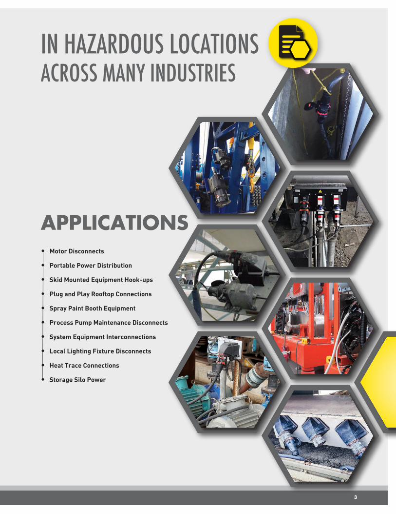
APPLICATIONS• Motor Disconnects
• Portable Power Distribution
• Skid Mounted Equipment Hook-ups
• Plug and Play Rooftop Connections
• Spray Paint Booth Equipment
• Process Pump Maintenance Disconnects
• System Equipment Interconnections
• Local Lighting Fixture Disconnects
• Heat Trace Connections
• Storage Silo Power
IN HAZARDOUS LOCATIONS ACROSS MANY INDUSTRIES

CONNECTION RELIABLITY
Spring-Assisted Terminals
• The spring assist on MELTRIC Terminals (20 A-250 A devices) compensates for the effects of vibration, strand settlement and temperature cycling, keeping the conductor securely connected and eliminating overheating failures due to loosened connections.
• Loosening of the terminal screws is a common cause of failure on other types of plugs and receptacles, but not with MELTRIC.
Spring-Loaded Silver-Nickel Butt Contacts
• Spring-loading maintains optimal contact force and eliminates overheating.
• Unlike brass, Silver-Nickel maintains high conductivity after oxidation in harsh environments.
• End-to-end mating eliminates the harmful effects of wear inherent with sliding contacts.
Spring
ReceptacleContact
Plug/InletContact
Flexible Braid
The split terminal causes the spring ring to deform from a circle to an ellipse as the terminal screw is tightened.
The spring ring, trying to return to its original circle shape, pushes the conductor and terminal screw tightly together. CONDUCTOR
Automatic Watertightness
• All MELTRIC hazardous location devices, except the PNCX, achieve their rated water and dust tightness simply by connecting the plug and receptacle.
• There are no additional twist or thread on rings that need to be engaged like most other types of plugs and receptacles.
• This eliminates the failures from users forgetting to engage the rings.
MELTRIC Advantages...
CONNECTION RELIABLITY
4
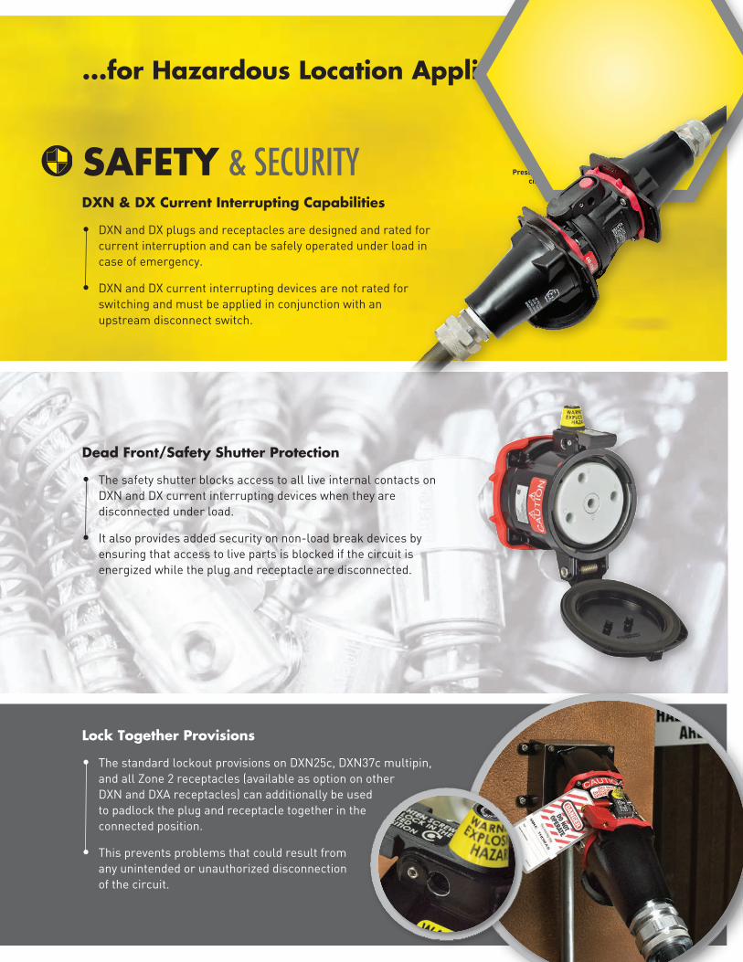
...for Hazardous Location Applications
DXN & DX Current Interrupting Capabilities
• DXN and DX plugs and receptacles are designed and rated for current interruption and can be safely operated under load in case of emergency.
• DXN and DX current interrupting devices are not rated for switching and must be applied in conjunction with an upstream disconnect switch.
SAFETY & SECURITY
Dead Front/Safety Shutter Protection
• The safety shutter blocks access to all live internal contacts on DXN and DX current interrupting devices when they are disconnected under load.
• It also provides added security on non-load break devices by ensuring that access to live parts is blocked if the circuit is energized while the plug and receptacle are disconnected.
Lock Together Provisions
• The standard lockout provisions on DXN25c, DXN37c multipin, and all Zone 2 receptacles (available as option on other DXN and DXA receptacles) can additionally be used to padlock the plug and receptacle together in the connected position.
• This prevents problems that could result from any unintended or unauthorized disconnection of the circuit.
Press to interrupt circuit
5

Simplify Lockout-Tagout
MELTRIC Advantages...
Convenient Disconnects Wherever They Are Needed
• DXN and DXA1 devices are horsepower and current interrupting rated making them perfect for use as emergency load break motor disconnects.
• Zone 2 DS and DSN devices are non-load break horsepower rated for use as convenient disconnects in motor circuits.
• Configuration flexibility allows placement near the equipment.
Power and Control in One Connection
• Models from 20 A to 250 A are available with optional auxiliary contacts allowing power, control, and signal circuits to all be connected through one device.
• Larger devices are available with up to 6 auxiliary contacts.
• The auxiliary contacts make last and break first.
OPERATIONAL EFFICIENCY
6
• Lockout provisions are standard on all 20 A to 250 A plugs/inlets, except the DX series, and allow them to be locked out with just a lock and tag.
• Receptacle lockout provisions are standard on some devices and available as a low-cost option on some others. They allow the receptacles to be locked out with the lid closed using either a 5/16” shank lock or an optional locking pin that accepts various sized locks. Locking the lid closed makes it impossible to insert a plug.

...for Hazardous Location Applications
Box or Panel Mount – Standard or ‘Reverse’ Service
• A variety of boxes and angles are available to facilitate wall or panel mounted applications.
• Reverse service is accomplished simply by mounting a standard inlet on the box or panel and mounting the standard receptacle on a handle at the end of the power cord.
Inline and Direct Mounted Configurations
• Inline cord-to-cord configurations are available for applications where portability is required.
• Threaded handles facilitate direct mounting to motors, threaded pipe conduit or other equipment or fittings to help provide convenient placement.
APPLICATION FLEXIBILITY
7
Suitable for Flexible Conduits
• Threaded handles accommodate liquidtight conduit fittings, simplifying wiring of multipin or power and control applications.
• Standard grounding provisions in metal handles facilitate the use of Teck or other armored cables.
8
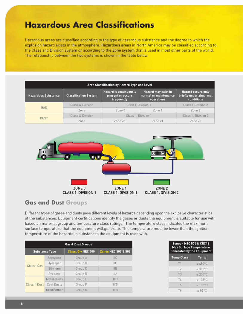
Hazardous Area Classifications
Hazardous areas are classified according to the type of hazardous substance and the degree to which the explosion hazard exists in the atmosphere. Hazardous areas in North America may be classified according to the Class and Division system or according to the Zone system that is used in most other parts of the world. The relationship between the two systems is shown in the table below.
Area Classification by Hazard Type and Level
Hazardous Substance Classification SystemHazard is continuously
present or occurs frequently
Hazard may exist in normal or maintenance
operations
Hazard occurs only briefly under abnormal
conditions
GASClass & Division Class I, Division 1 Class I, Division 2
Zone Zone 0 Zone 1 Zone 2
DUSTClass & Division Class II, Division 1 Class II, Division 2
Zone Zone 20 Zone 21 Zone 22
Gas and Dust Groups
Different types of gases and dusts pose different levels of hazards depending upon the explosive characteristics of the substances. Equipment certifications identify the gases or dusts the equipment is suitable for use with based on material group and temperature class ratings. The temperature class indicates the maximum surface temperature that the equipment will generate. This temperature must be lower than the ignition temperature of the hazardous substances the equipment is used with.
Gas & Dust Groups
Substance Type Class, Div NEC 500 Zones NEC 505 & 506
Class I Gas
Acetylene Group A IIC
Hydrogen Group B IIC
Ethylene Group C IIB
Propane Group D IIA
Class II Dust
Metal Dusts Group E IIIC
Coal Dusts Group F IIIB
Grain/Other Group G IIIB
Zones - NEC 505 & CEC18Max Surface Temperature
Generated by the Equipment
Temp Class Temp
T1 ≤ 450°C
T2 ≤ 300°C
T3 ≤ 200°C
T4 ≤ 135°C
T5 ≤ 100°C
T6 ≤ 85°C

9
DIVISIONMELTRIC Products for Hazardous Areas
ZONE
Electrical equipment used in hazardous areas must be rated for the type of environment it is used in or it can be rated for a more hazardous environment. For example, Zone 2 or Division 2 rated equipment may only be used in Zone 2 or Division 2 classified areas, while Zone 1 rated equipment may be used in either Zone 1 or Zone 2 classified areas and Division 1 rated equipment may be used in Division 1 or Division 2 classified areas.
Product Series Hazardous Substance Certification Allowed Usage Areas are highlighted in Yellow
DXN and DXACurrent Interrupting
Class 1/GASCSA Division 1 Division 2
CSA, ATEX, IECEx Zone 0 Zone 1 Zone 2
Class 2/DUSTCSA Division 2 Division 2
CSA, ATEX, IECEx Zone 20 Zone 21 Zone 22See pg 10
Zone 2Non-Current Interrupting Class 1/GAS
CSA Division 1 Division 2
CSA Zone 0 Zone 1 Zone 2See pg 12
SPeXSingle Pole
Class 1/GASCSA Division 1 Division 2
CSA, ATEX, IECEx Zone 0 Zone 1 Zone 2
Class 2/DUSTCSA Division 1 Division 2
CSA, ATEX, IECEx Zone 20 Zone 21 Zone 22See pg 14
PXN and DXNMultipin
GAS ATEX, IECEx Zone 0 Zone 1 Zone 2
DUST ATEX, IECEx Zone 20 Zone 21 Zone 22See pg 16
DXCurrent Interrupting
GAS ATEX, IECEx Zone 0 Zone 1 Zone 2
DUST ATEX, IECEx Zone 20 Zone 21 Zone 22See pg 18
PNCXNon-Current Interrupting
GAS ATEX, IECEx Zone 0 Zone 1 Zone 2
DUST ATEX, IECEx Zone 20 Zone 21 Zone 22See pg 20
SBEnclosures
Class 1/GASUL Division 1 Division 2
ATEX, IECEx Zone 0 Zone 1 Zone 2
Class 2/DUSTUL Division 1 Division 2
ATEX, IECEx Zone 20 Zone 21 Zone 22See pg 22

• Larger Aluminum Casing
• 20 A
• Up to 7.5 hp, 600 VAC
• Current Interrupting
• Dual Pawl Latching
• IP66/IP67
• -67˚F to 140˚F
• Compact Poly Casing
• 20, 30, and 60 A Models
• Up to 20 hp, 600 VAC
• Current Interrupting
• Push Button Release
• IP66/IP67
• -40˚F to 140˚F
• Available with Auxiliary Contacts up to 550 VAC
Inline Configuration
Current Interruption Rating - What does it Mean to Users?
DXN and DXA devices are rated for current interrupting and thus can safely be connected and disconnected under load, up to their rated amperage and horsepower. They provide a convenient disconnection means for motors and other equipment in hazardous areas and assure user safety in the event of emergency, accidental or occasional disconnection under load. They are not rated for regular switching duty, so there must be a safety switch installed upstream in the circuit.
DXN & DXA Zone 1/21
cCSAus Listed for use in the Following Areas
GAS Zone 1 Zone 2 Class I Division 2
DUST Zone 21 Zone 22 Class II Division 2
DXN DXA
Current Interrupting Plugs and Receptacles – 20 A to 60 A
10
cCSAus Amperage & Horsepower Ratings
Model/Amp DXN2020 A
DXN3030 A
DXN6060 A
DXA120 A
120V 1Ø 0.75 hp 1 hp 2 hp .75hp
208V 1Ø 1 hp 2 hp 3hp 1 hp
240V 1Ø 2 hp 3 hp 3 hp 2 hp
277V 1Ø 2 hp 3 hp 5 hp 2 hp
480V 1Ø 3 hp 5 hp 7.5 hp 3 hp
600V 1Ø 3 hp 7.5 hp 10 hp 3 hp
208V 3Ø 3 hp 5 hp 7.5 hp 3 hp
240V 3Ø 3 hp 5 hp 7.5 hp 3 hp
480V 3Ø 7.5 hp 10 hp 20 hp 7.5 hp
600V 3Ø 7.5 hp 15 hp 20 hp 7.5 hp
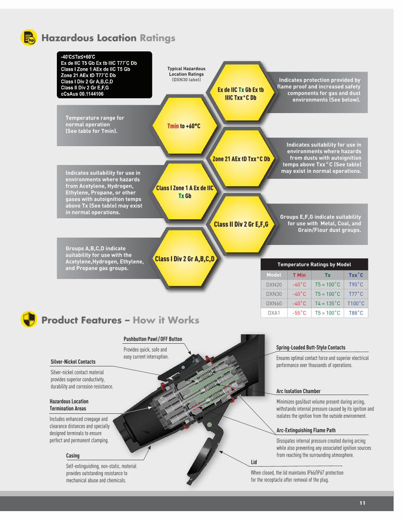
Tmin to +60°C
Class I Zone 1 A Ex de IICTx Gb
Groups A,B,C,D indicate suitability for use with the Acetylene,Hydrogen, Ethylene, and Propane gas groups.
Hazardous Location Ratings
Zone 21 AEx tD Txx˚C Db
Class II Div 2 Gr E,F,G
Temperature range for normal operation(See table for Tmin).
Indicates suitability for use in environments where hazards from Acetylene, Hydrogen, Ethylene, Propane, or other gases with autoignition temps above Tx (See table) may exist in normal operations.
Indicates protection provided by flame proof and increased safety
components for gas and dust environments (See below).
Ex de IIC Tx Gb Ex tb IIIC Txx˚C Db
Indicates suitability for use in environments where hazards
from dusts with autoignition temps above Txx˚C (See table)
may exist in normal operations.
Groups E,F,G indicate suitability for use with Metal, Coal, and
Grain/Flour dust groups.
Temperature Ratings by Model
Model T Min Tx Txx˚C
DXN20 -40˚C T5 = 100˚C T90˚C
DXN30 -40˚C T5 = 100˚C T77˚C
DXN60 -40˚C T4 = 135˚C T100˚C
DXA1 -55˚C T5 = 100˚C T88˚C
Product Features – How it Works
Silver-Nickel Contacts
Silver-nickel contact material provides superior conductivity, durability and corrosion resistance.
Casing
Self-extinguishing, non-static, material provides outstanding resistance to mechanical abuse and chemicals.
Pushbutton Pawl / OFF Button
Provides quick, safe and easy current interruption.
Spring-Loaded Butt-Style Contacts
Ensures optimal contact force and superior electrical performance over thousands of operations.
Hazardous Location Termination Areas
Includes enhanced creepage and clearance distances and specially designed terminals to ensure perfect and permanent clamping.
Arc Isolation Chamber
Minimizes gas/dust volume present during arcing, withstands internal pressure caused by its ignition and isolates the ignition from the outside environment.
Arc-Extinguishing Flame Path
Dissipates internal pressure created during arcing while also preventing any associated ignition sources from reaching the surrounding atmosphere.
Lid
When closed, the lid maintains IP66/IP67 protection for the receptacle after removal of the plug.
Class I Div 2 Gr A,B,C,D
Typical HazardousLocation Ratings
(DXN30 label)
11
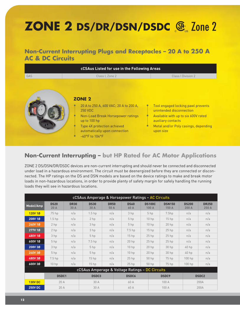
Non-Current Interrupting – but HP Rated for AC Motor Applications
ZONE 2 DS/DSN/DR/DSDC devices are non-current interrupting and should never be connected and disconnected under load in a hazardous environment. The circuit must be deenergized before they are connected or discon-nected. The HP ratings on the DS and DSN models are based on the device ratings to make and break motor loads in non-hazardous locations, in order to provide plenty of safety margin for safely handling the running loads they will see in hazardous locations.
ZONE 2 • 20 A to 250 A, 600 VAC; 20 A to 200 A,
250 VDC
• Non-Load Break Horsepower ratings up to 100 hp
• Type 4X protection achieved automatically upon connection
• -40°F to 104°F
• Tool engaged locking pawl prevents unintended disconnection
• Available with up to six 600V rated auxiliary contacts
• Metal and/or Poly casings, depending upon size
cCSAus Listed for use in the Following Areas
GAS Class I, Zone 2 Class I Division 2
Non-Current Interrupting Plugs and Receptacles – 20 A to 250 AAC & DC Circuits
Zone 2ZONE 2 DS/DR/DSN/DSDC
cCSAus Amperage & Horsepower Ratings – AC Circuits
Model/Amp DS2020 A
DR3030 A
DS3030 A
DR5050 A
DS6060 A
DS100C 100 A
DSN150 150 A
DS200 200 A
DR250250 A
120V 1Ø .75 hp n/a 1.5 hp n/a 3 hp 5 hp 7.5hp n/a n/a
208V 1Ø 1.5 hp n/a 2 hp n/a 5 hp 10 hp 15 hp n/a n/a
240V 1Ø 2 hp n/a 3 hp n/a 5 hp 10 hp 20 hp n/a n/a
277V 1Ø 2 hp n/a 3 hp n/a 7.5 hp 15 hp 25 hp n/a n/a
480V 1Ø 3 hp n/a 5 hp n/a 15 hp 25 hp 25 hp n/a n/a
600V 1Ø 5 hp n/a 7.5 hp n/a 20 hp 25 hp 25 hp n/a n/a
208V 3Ø 3 hp n/a 5 hp n/a 10 hp 20 hp 30 hp 40 hp n/a
240V 3Ø 5 hp n/a 5 hp n/a 10 hp 20 hp 30 hp 40 hp n/a
480V 3Ø 7.5 hp n/a 15 hp n/a 25 hp 50 hp 75 hp 100 hp n/a
600V 3Ø 10 hp n/a 15 hp n/a 25 hp 50 hp 75 hp 100 hp n/a
12
cCSAus Amperage & Voltage Ratings – DC CircuitsDSDC1 DSDC3 DSDC6 DSDC9 DSDC2
130V DC 20 A 30 A 60 A 100 A 200A
250V DC 20 A 30 A 60 A 100 A 200A

Class I,Division 2
Class I, Zone 2
Hazardous Location Ratings
T6
IIC
Suitable for environments where explosive gas may appear briefly under abnormal conditions.
Suitable for environments where explosive gas may appear briefly under abnormal conditions.
Suitable for Propane, Ethylene, Hydrogen, and Acetylene gases.Groups ABCD
The product can be used around substances with autoignition
temperatures as low as 85°C.
Suitable for Propane, Ethylene, Hydrogen, and Acetylene gases.
Typical Device Label. All Zone 2 products in this section have similar Hazardous Location Ratings.
13
Product Features – How it Works
Locking Pawl
The hazardous location ratings of these products are based on the use of the screw-type locking pawl.
• After connection, the screw lock must be engaged to prevent unintended disconnection.
• The lock must be unscrewed with the tool before the device can be disconnected.
For added security, a lockout hole in the pawl allows the device to additionally be padlocked in the connected position. It also allows the receptacle lid to be padlocked in the closed position to prevent the unintended connection of a plug.
Contact Technology
• Spring-Loaded Silver-Nickel Butt Contacts ensure a safe connection over thousands of operations and in harsh environments.
Auxiliary Contacts
• Optional auxiliary contacts allow power, control, and monitoring circuits to all be connected through one device.
Screw-Type Locking Pawl
Tool required for
disconnectionPadlock for extra security
Silver-Nickel
AuxiliaryContacts
Spring-Loaded

14
The pilot circuit must be wired and used to control the power to the device.
• When the pilot circuit is open the power is off, the latch is unlocked, and the device may be safely connected and disconnected.
• Once a plug is inserted, twisting the interlock ring clockwise to the ON position locks the latch, preventing removal of the plug, and closes the pilot circuit allowing power to flow.
• Returning the interlock ring to the OFF position opens the pilot circuit, causes the power to be switched off, and unlocks the latch allowing the plug to be removed.
Mechanical Interlocked Pilot Circuit - Prevents Operation Under Load
cCSAus Listed for use in the Following Areas
GAS Zone 1 Zone 2 – Class I Division 2
DUST Zone 21 Zone 22 Class II Division 1 Class II Division 2
Single Pole Plug and Receptacle – 600 A for AC Circuits
SPeX Zone 1/21
Pilot Circuit is closed, Power is ON
Latch is locked.Plug cannot be removed.
Rotate Ring back to Turn OFF
Latch unlocks.Plug may be removed.
Pilot Circuit is open, power is OFF
Latch is unlocked. Plug can be inserted.
Rotate clockwise to Turn Power ON
Latch locks the plug and receptacle together.
• CSA up to 600 A, 600 VAC
• ATEX to 1000 VAC, 1500 VDC
• Mechanical/Electrical Interlock
• Wire Capacity 2/0 AWG to 750 MCM
• Phases are keyed, color-coded and
labeled
• IP65/IP66
• -20°C to +40°C or +60°C, based on Environment
• Pilot wire capacity of 14 - 12 AWG
Pilot Connections
Integral pilot circuit for controlling the power circuit.
Mechanical/Electrical Interlock
Twist ring closes/ opens the pilot circuit and locks / unlocks the latching mechanism which works with a breaker to prevent connection or disconnection under load.
Silver Contact Material
Enables maximum performance and durability – withstands at least 2000 operations.
Protective Caps
Protect contacts when disconnected.
Latch Release Button
Enables disconnection of the plug from the receptacle.

15
Class II Division 1 Groups E, F, G
Hazardous Location Ratings
-20°C ≤ Ta ≥ Tmax Tx Txx (see Table)
Includes Metal, Coal, and Grain/Flour dust groups in environments where the hazard is continuously present.
Covers Acetylene, Hydrogen, Ethylene & Propane gas groups in
environments where the hazard may occur in normal conditions.Safe for gases with autoignition
temps above Tx (See table).
Class I Zone 1 AEx e IIC T5 (or T6 see table)
Temperature range for normal operation (see Table for Tmax).Safe for gases with autoignition
temps above Tx (see table). Safe for dusts with autoignition temps above Txx°C (See table).
Temperature Ratings by Model
T Max Tx Txx˚C
+60˚C T5 = 100˚C T76˚C
+40˚C T6 = 85˚C T56˚C
Other Product Features
Phase Identification Drawbar Mechanism
Makes Connection Easy
Wiring Capacity
I.D. Flex Course
min .43 in 1/0 AWG 2/0 AWG
max 1.15 in 777 MCM 800 MCM
(Bolt Included)
Bolt-On Threaded
Lugs
Color-Coded
Color-Coded
Receptacle on Angle PlugPlugs are available with 4 different handle cord grip sizes, accommodating cable diameters of 0.70 - 1.89 inches.
Available Configurations
Labeled
Labeled
Keyed
Keyed

16
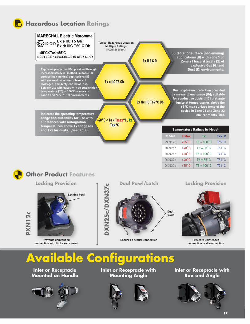
DXN & PXN Zone 1/21
Multipin Plugs and Receptacles – 10 A for AC & DC CircuitsNot for Current Interrupting
ATEX & IECEx Listed for use in the Following Areas
GAS Zone 1 Zone 2
DUST Zone 21 Zone 22
PXN12c• 10 A, 220 VAC or VDC
• 12 Contacts
• IP65/IP66
• -40˚C to +55˚C
• Metal Casings
• Crimp/Solder Terminals
• Locking provision preventsunintended disconnection
DXN25c/DXN37c• 10 A, 440 VAC or VDC (DXN25c)
• 10 A, 230 VAC or VDC (DXN37c)
• 25 or 37 Contacts
• IP66/IP67
• -40˚C to +55˚C or 60°C
• Metal Casings
• Crimp/Solder Terminals
• Locking provision prevents unintended disconnection
Simplified Contact Termination, Assembly, and Disassembly
Conductor Terminations
• The contacts accept wire sizes of 16 to 14 AWG or 1.0 - 2.5 mm2.
• The conductors may be terminated by crimping or by solderingthem into the contacts.
• Ferrules are provided to help contain loose strands and heat shrinktubing is provided to ensure effective insulation of the terminationand between contacts.
Conductor Terminations Conductor Terminations
Once the terminations are complete, the contacts can be assembled into the device by pushing the contact into the appropriate contact hole (from the backside of the device) until they are firmly seated in the insulator.
A special tool is provided for contact removal. Push the hollow end of the tool around the o.d. of the contact until it stops. The contact will then be released. A contact may be inserted/removed 3 times.
Cable Insulation sleeve
Ferrule Female contact silver
plated
17
Locking Provision
Prevents unintended connection with lid locked closed
Ex e IIC T5 Gb
-40°C < Ta > Tmax°C, Tx Txx°C
Hazardous Location Ratings
Ex tb IIIC T69°C Db
Explosion protection (Ex) provided through increased safety (e) method, suitable for surface (non-mining) applications (II) with gas explosion hazard levels of Hydrogen, and Acetylene (C) or less. Safe for use with gases with an autoignition temperature (T5) of 100°C or more in Zone 1 and Zone 2 (Gb) environments.
Indicates the operating temperature range and suitability for use with substances with autoignition temperatures above Tx for gases and Txx for dusts. (See table).
Suitable for surface (non-mining) applications (II) with Zone 1 or
Zone 21 hazard levels (2) of explosive Gas (G) and
Dust (D) environments.
Ex II 2 G D
Dust explosion protection provided by means of enclosure (tb); suitable for conductive dusts (IIIC) that auto
ignite at temperatures above the 69°C max surface temp of the device in Zone 21 and Zone 22
environments (Db).
Temperature Ratings by Model
Model T Max Tx Txx˚C
PXN12c +55˚C T5 = 100˚C T69˚C
DXN25c +40˚C T6 = 85˚C T51˚C
DXN25c +60˚C T5 = 100˚C T71˚C
DXN37c +40˚C T6 = 85˚C T56˚C
DXN37c +55˚C T5 = 100˚C T76˚C
Other Product Features
Typical Hazardous Location Multipin Ratings (PXN12c label)
Dual Pawl/Latch
Ensures a secure connection
Locking Provision
Prevents unintended connection or disconnection
Inlet or Receptacle Mounted on Handle
Inlet or Receptacle with Mounting Angle
Inlet or Receptacle with Box and Angle
Available Configurations
Dual Pawls
PXN
12
c
DX
N25
c/D
XN
37
c
Locking Pawl

Current Interrupting Plugs and Receptacles – 20 A to 125 A
Zone 1/21DX
Heavy-Duty Aluminum Casing
All components are enclosed in rugged copper free aluminum housings for maximum durability and protection.
Arc Isolation Chamber
Minimizes gas/dust volume present during arcing, withstands internal pressure caused by its ignition of it and isolates the ignition from the outside environment.
Silver-Nickel Butt Contacts
Contact design provides a superior connection, with maximum conductivity, the ability to withstand arcing and oxidation, excellent wear resistance, and a long operating life. A wiping motion during operation also provides a self-cleaning action.
Spring Operated Switching Mechanism
An integral switching mechanism ensures quick-make, quick-break operation, independent of the motion of the user.
Dead Front
The ‘dead’ load-side switching contacts block access to the receptacle and are locked in the open position until an appropriate mating plug is fully inserted. This prevents unintended access to live parts and ensures user safety.
Load Break Switching Mechanism
DX devices are equipped with a quick-make quick-break internal switching mechanism, which essentially functions like a rotary switch. The plug can only be inserted into the receptacle when the receptacle contacts are in the OFF position. The power remains off until the plug is rotated clockwise to the ON position, which trips the switch causing the receptacle contacts, the plug contact and downstream load to be energized. The plug cannot be removed while it is in the ON position.
ATEX/IECEx Amperage
Model/Amp DX120 A
DX332 A
DX663 A
DX9125 A
VAC max 750 750 750 750
All models are available in US and International voltage configurations
ATEX & IECEx Listed for use in the Following Areas
GAS Zone 1 Zone 2
DUST Zone 21 Zone 22
• Integrated Load break Switch
• Rated up to 750 VAC
• Heavy Duty Aluminum Casing
• -25°C to +60°C or -40°C to +60°C
• IP65/IP66 Water and Dust Protection
• IK10 Impact protection
Plug inserts to OFF position remains
deenergized
Plug connects and disconnects
only from the OFF position
18
Rotation to ON position energizes
the receptacle contacts and plug

b
a
Ex de IIC
Tmin ≤ Ta ≥ +60°C Tx Txx°C (see Table)
Hazardous Location Ratings
tD A21
Explosion protection (Ex) provided thru flameproof (d) and increased safety (e) methods, suitable for surface (non-mining) applications (II) with gas explosion hazard levels of Hydrogen and Acetylene (C) or less.
Temperature range for normal operation (See table for Tmin).
Safe for gases with autoignition temps above Tx (See table).
Safe for dusts with autoignition temps above Txx°C (See table).
Suitable for explosive Gas and Dust (G/D) environments in
surface (non-mining) applications (II) with Zone 1 or Zone 21
hazard levels (2)
II 2 G/D
Dust explosion protection provided by means of Housing
(tD) with a leak tightness suitable for Zone 21 (A21)
Temperature Ratings by Model
Model T Min Tx Txx˚C
DX1 -25°C T5 = 100°C T84°C
DX3 -25°C T5 = 100°C T84°C
DX6 -40°C T5 = 100°C T90°C
DX9 -40°C T5 = 100°C T90°C
Alternative T6 = 85°C rating reduces Tmax to +50°C and reduces Txx by 10°C
19
Inlet or Receptacle Mounted on Handle
Inlet or Receptacle Mounted on Box
Receptacle
Available Configurations
Receptacle with Plug Disconnected
Live power contact (a) is isolated from the dead receptacle contact (b)
Insertion of Plug
Connected plug and receptacle contact are dead and isolated
from the power contact
Rotation of plug to ON position
Rotation winds then releases the operating spring to achieve
a quick-make connection
Rotation of plug back to OFF position
Rotation back releases the remaining spring energy for a quick-break of the connection
Product Features – How it Works
Typical DX Hazardous Location Ratings
(DX30 label)

20
PNCX
• Spring-loaded silver-nickel contacts maintain high conductivity in harsh environments
• Suitable for low power 4 - 20mA control signals
• Device locks, connecting and engaging water/dust protection by the simple 40° rotation of a locking ring
• Panel mounting requires drilling only a single 1” hole
• Screw terminals simplify wiring
Small Footprint for Low Power and Control Circuits
PNCX devices provide convenient and reliable hazardous location connections for control signal and low amperage power circuits. Their small size helps keep panel or enclosure dimensions to a minimum and installation is quick and easy.
Zone 1/21
Compact Non-Current Interrupting Plugs and Receptacles – 5A
• 5 A, 250V non-current interrupting
• IP66/IP67/IP69 Water and Dust Protection
• Contact configuration 3P + N + G
• -25°C to +70°C
• Cable Range: 0.4 - 0.55”, 10 - 14mm
• Wire Capacity: 20 - 14AWG, .75 mm to 2.5 mm
• Thermoplastic Casing
• Screw Terminals
ATEX & IECEx Listed for use in the Following Areas
GAS Zone 1 Zone 2
DUST Zone 21 Zone 22
Panel Mount Receptacle Dimensions Use of standard caps maintains IP ratings when disconnected
.99”
2.28”
1.78”
Requires 1.0” Panel Mounting Hole
1.0”
PNCX

21
Ex e IIC T6 Gb
Key Hazardous Location Ratings
Ex tb IIIC T72˚C Db
Explosion protection (Ex) provided through increased safety (e) method, suitable for surface (non-mining) applications (II) with gas explosion hazard levels of Hydrogen and Acetylene (C) or less. Safe for use with gases with an autoignition temperature (T6) of 85°C or more in Zone 1 and Zone 2 (Gb) environments.
Suitable for surface (non-mining) applications (II) with Zone 1 or
Zone 21 hazard levels (2) of explosive Gas(G) and Dust (D)
environments.
Ex II 2 G D
Dust explosion protection provided by means of enclosure (tb); suitable
for combustible metal dusts (IIIC) that auto ignite at temperatures
above the 72°C max surface temp of the device in Zone 21
& Zone 22 environments (Db).
Product Features – How it Works
Align keying rib on plug with slot on receptacle
Insert plug into receptacle Rotate ring 40° to lock device together and engage water and dust ingress protection
Inlet or Receptacle(with Retention Nut for Panel Mounting)
Plug or Power Connector (Inlet or Receptacle with a Handle)
Available Configurations
21
Connector and Plug Disconnected
Insertion of Plug Rotation of ring

22
SB Enclosures
Available as Empty Enclosures or Custom Assembled Panels
• Hinged doors or bolt on covers
• Available with or without side gland plates
• Entry sizes from .75” to 3.125”
• Max number of entries based on box size, see table
• Viewing windows, internal DIN rail, mounting plates, ground studs, and breather drains can be added
Class I, Division 2
Stainless Steel Enclosures
Certification UL ATEX and IECEx
GAS Class I, Division 2* Zone 1 Zone 2
DUST n/a Zone 21 Zone 22
* Based on UL508A and Type 4X certification plus NEC code allowances.
• Stainless Steel - AISI 316L - 1.5MM thick
• Silicone Rubber Gaskets
• Type 4X & 12, IP66/IP67 Environmental ratings
• Standard sizes up to 19.5” x 19.5” x 6.25”
• Custom sizes up to 35.75” x 44.75” x 19.5”
• Available empty or as assembled panels
• Maximum entry size of 3.125”
Terminal Boxes
E-Stops
Multi-Function Panels
Push Buttons
Selector Switches
Distribution Boxes

23
II 2 G Ex e IIC Gb
Key Hazardous Location Ratings
II 2 D Ex tb IIIC Db
Suitable for surface (non-mining) applications (II) with Zone 1 or Zone 21 hazard levels (2) of explosive Gas (G) environments. Explosion protection (Ex) provided through increased safety (e) method, suitable for gas explosion hazard levels equivalent to Hydrogen, Acetylene (IIC) or less in Zone 1 and Zone 2 (Gb) environments.
UL 508A, Type 4X
Suitable for surface (non-mining) applications (II) with Zone 1 or Zone 21 hazard levels
(2) of explosive dust (D) environments. Explosion protection (Ex) provided by means of enclosure (tb); suitable for
conductive dusts (IIIC) in Zone 21 and Zone 22 environments (Db).
Standard Enclosure Dimensions and Entry and Terminal Capacities
PART
NUMBER
DIMENSIONS (mm)*MAXIMUM
CABLE ENTRIES W/O GLAND PLATE
MAXIMUMCABLE ENTRIES W/GLAND PLATE
MAX NUMBER OF TERMINALS WEIGHT
(KG)A B C D E SIDE A SIDE B SIDE A SIDE B 2,5 MM2 4 MM2
SB-101210** 100 120 100 150 – 4 4 – – 7 6 1.5
SB-151510** 150 150 100 180 – 6 6 – – 13 11 2.5
SB-202010 200 200 100 230 160 9 9 – – 22 19 3
SB-142013 140 200 130 170 160 6 10 4 4 11 9 4
SB-202713 200 270 130 230 230 10 14 6 6 36 30 7
SB-273513 270 350 130 300 310 14 18 8 8 72 60 9.5
SB-302016 300 200 160 330 160 21 15 12 8 44 38 5
SB-353516 350 350 160 380 310 27 27 16 16 102 86 5.6
SB-355016 350 500 160 380 460 27 39 16 24 160 134 13
SB-505016 500 500 160 530 460 39 39 24 24 240 201 14.5
SB-384516 380 450 160 410 410 30 36 18 20 171 144 10.7
SB-577620 570 760 200 600 720 73 98 54 74 558 468 21.7
SB-769520 760 950 200 790 910 98 125 74 94 990 834 32.9
* Upon request, any dimension between 100x120x100 mm and 910x1140x500 mm can be manufactured.** The enclosure is only available without hinges.
Gas T6 T5 T4
Dust T85°C T100°C T135°C
As permitted by Article 500.8 (B)(3) and other related sections of the
NEC, equipment in general purpose enclosures may be used in Class I,
Div 2 environments provided it does not constitute a source of ignition
under normal operating conditions.
A
B
D
EC
A
B
D
EC
A
B
DE
C
EnclosureUL: 508A, Type 4XAtex/IECEx: II 2 G Ex e IIC GbAtex/IECEx: II 2 D Ex tb IIIC Db
Temperature RatingsUL: -40°C to + 40°C Atex: -50°C to +60°CIECEx: -50°C to + 95°C

Plug into SAFETY and RELIABILITY with MELTRIC
meltric.com4765 W. Oakwood Park Drive • Franklin, WI 53132414-433-2700 • Fax 414-433-2701©2021 MELTRIC Corporation. All rights reserved. HAZLOC_A
DIVISION
ZONE
Our friendly engineering and customer service teams are available Monday - Friday, 7 a.m. - 5 p.m. (Central Time)
Phone: 414-433-2700Email: [email protected]
Need it quickly? Most orders ship within 2 days.
MELTRIC Connection Solutions for Hazardous Locations
Multipin
• Up to 37 Contacts
• Crimp or Solder Terminals
PNCX• Compact Size for Low
Power (5 Contacts)• Quick-Make Quick-Break
• Current Interruption
DX
SPeX
• Single Pole with Mechanical Interlock - 600 A
• Stainless Steel Enclosures
• Available Empty or as Custom Assemblies
SBDXN
• Current Interrupting up to 60 A or 25 hp
Zone 2
• 20 A-250 A with up to 6 Auxiliary Contacts
Please note, Hazardous Location products are non-returnable.

Understanding North American Ratings Understanding Atex IECEx Ratings and MarkingsClass and Division (NEC Section 500) Zones (NEC Section 505 & 506)
Class I Division 2 Groups A B C D Class I Zone 1 AEx de IIC T5 Gb
Class II Division 2 Groups E F G Class II Zone 21 AEx tD IIIC T77˚C Db
Hazard Class - See Table 1
Area Classification - See Table 1
Hazardous Material Grouping - See Table 2
Indicates Approval to American Standards
Method of Protection - Table 6
Temperature Class - See Table 3
Typical Markings - DXN30 is shown Equipment Protection Level - See Table 1
Table 2 - Material Groups
Hazardous Substance
Class & Division Group
Flammability Properties* Zone Group Example Materials
Gases
A Acetylene IIC Acetylene
B MESG ≤ .45 MIC ≤ .40 IIC Hydrogen
C .45 < MESG ≤ .75 .40 < MIC ≤ .80 IIB Ethylene
D MESG > .75 MIC > .80 IIA Propane, Methane, Ammonia
Dusts
E Combustible Metal Powder IIIC Aluminum, Magnesium
F Combustible Carbonaceous Dusts IIIB Coal, Coke, Carbon Black, Charcoal
G Other Combustible Dusts IIIB Flour, Grain, Wood, Polymer, Chemical
Fibers - Ignitable Fibers and Flying IIIA Cotton, Rayon, Cocoa, Jute, Hemp
* MESG and MIC listed based on NEC 500. NEC 505 values vary slightly. The MESG (maximum experimental safety gap) is the maximum gap between two flat surfaces that prevents an ignition of a gas/air mixture from propagating thru a 25mm long pathway. The smaller the MESG, the higher the explosion hazard of the substance. The MIC (minimum ignition current) ratio is the minimum current required to ignite a gas or vapor compared to the minimum current to ignite methane. The lower the MIC ratio, the more explosive the substance is.
Table 3 - Temperature Class
GasTemperature Class T1 T2 T3 T4 T5 T6
Maximum Allowed Surface Temperature
450˚C 300˚C 200˚C 135˚C 100˚C 85˚C
DustActual Maximum Surface Temperature Generated
Txxx˚C, where xxx is the actual maximum surface temperature the product generates
The purpose of the temperature class is to prevent the use of products that will generate a surface temperature that is hot enough to ignite the gas or dust substances in the atmosphere that it comes in contact with. See table 5 for some gas autoignition temperatures.
Table 4 - Classification and Ratings Requirements of Hazardous Locations
Explosive Atmosphere
Frequency of Explosive Atmosphere Occurrence
Classification of Hazardous Location
Product Classification Equipment Protection Level
(EPL)Product Group
Equipment Category
Gases, Mists
or Vapors
Continuously or for long periods Zone 0 II
1G GaLikely to occur in
Normal ConditionsZone 1 II
2G GbInfrequently and only
for short periodsZone 2 II 3G Gc
Dusts
Continuously or for long periods Zone 20 II
1D DaLikely to occur in
Normal ConditionsZone 21 II
2D DbInfrequently and only
for short periodsZone 22 II 3D Dc
Product Group II indicates ratings for surface (non-underground mining) applications. The 1G (and/or Ga) rating indicates suitability for Zone 0, 1 and 2 gas environments, while the 2G (and/or Gb) rating is suitable for Zones 1 and 2, and 3G (and/or Gc) is suitable only for Zone 2. Similarly, the 1D (and/or Da) rating indicates suitability for Zone 0, 1 and 2 dust environments, while the 2D (and/or Db) rating is suitable for Zones 1 and 2, and 3D (and/or Dc) is suitable only for Zone 2.
Table 5 - Gas Explosion Groups & Temperature Classes
Gas Explosion Group
Autoignition Temps of Some Group IIA, IIB & IIC Gases and Temp Class Tx required for use with them
IIC
IIB
IIA
>450°C >300°C >200°C >135°C >100°C >85°C
Ammonia Methane Propane
Ethanol n-butane
Gasoline Kerosine
Ethylene Di-ethyl ether
Hydrogen AcetyleneCarbon
disulfide
The Temp Class, Tx,
indicates the max surface temp of the
product
T1 <450°C
T2 <300°C
T3 <200°C
T4 <135°C
T5 <100°C
T6 <85°C
The required equipment rating, Tx, depends on the gases in the environment. For example, carbon disulfide, which is very explosive and has a low 90°C autoignition temperature, requires the highest group IIC and temperature class T6 protection ratings. Propane, which poses a lower explosion hazard and has a high autoignition temperature, requires only the lowest IIA and T1 ratings.
Table 6 - Common Protection Method Markings for Zone Locations ATEX/IECEx and North American (Red specific to the US)
Protection Method Rating CodeUsable in Zones
Protection Method Rating CodeUsable in Zones
Gas Dust Gas Dust
Contains explosion within the enclosure
Flameproof Enclosure Ex d AEx d
da 0, 1, 2 Positive pressure prevents gas or
dust entryPurged & pressurized Ex p AEx p
pxb 1, 2 21, 22
db 1, 2 pyb 1, 2 21, 22
dc 2 pzc 2 22
Prevents sparks & high temperatures
Increased Safety Ex e AEx eeb 1, 2 Isolation from Ex
atmosphereOil Immersion Ex o AEx o
ob 1, 2
ec 2 oc 2
Low current, voltage and temperature
Intrinsic Safety Ex i AEx i
ia 0, 1, 2 20, 21, 22Quench the flame
within the enclosurePowder Filling Ex q AEx q qb 1, 2ib 1, 2 21, 22
ic 2 22
External barrier prevents gas or dust entry
Encapsulation Ex m AEex m
ma 0, 1, 2 20, 21, 22Dust explosion
proofProtection by Enclosure Ex t AEx t
ta 20, 21, 22
mb 1, 2 21, 22 tbtD
21, 22
mc 2 22 tc 22
LEG
END
LEG
END
Sample ATEX IECEx Gas Rating Sample ATEX IECEx Dust Rating Sample ATEX IECex Gas Rating Sample ATEX IECex Dust Rating
Ex Approval mark for EU certification IIC/IIIC Explosion GroupIIA = Propane
IIB = Ethylene (+ IIA gases) IIC = Hydrogen (+ IIA & IIB gases)
IIIA = Combustible Dust IIIB = Non-conductive Dust (+IIIA)
IIIC = Conductive Dust (+IIIA & IIIB)
II Equipment Group: I - Underground MiningII = Surface Applications
(All other than underground Mining)Gb/Db
Equipment Protection Level: (See Table 4)
Ga = (Gas) Zone 0 (+Zones 1 & 2) Gb = (Gas) Zone 1 (+Zone 2)
Gc = (Gas) Zone 2
Da = (Dust) Zone 20 (+Zone 21&22) Db = (Dust) Zone 21 (+Zone 22)
Dc = (Dust) Zone 22
2G/2DEquipment Group:
(See Table 4)
1G = (Gas) Zone 0 (+Zones 1 & 2) 2G = (Gas) Zone 1 (+Zone 2)
3G = (Gas) Zone 2
1D = (Dust) Zone 20 (+Zone 21&22) 2D = (Dust) Zone 21 (+Zone 22)
3D = (Dust) Zone 22
T6/T51˚C
Temperature Class: (See Table 5)The max surface temperature of the
product is coded by a T1, T2, T3, T4, T5 or T6 marking. (See Table 2)
The max surface temperature the product generates is indicated directly in the rating, such as T51°C.
EX e/Ex tb Explosion Protection provided by means of: d, e, l, p, m, o, q, or t (See table 6)
meltric.com
Table 1 - Class, Division and Zone Location Classifications
Hazardous Substance Frequency of Explosive Atmosphere Occurrence Hazardous Location Classification Equipment Protection Level
Gases, Mists or Vapors
Continuously or for long periods
Class IDivision 1
Zone 0 Ga
Likely to occur in Normal Conditions Zone 1 Gb
Infrequently and only for short periods Division 2 Zone 2 Gc
Dusts
Continuously or for long periods
Class IIDivision 1
Zone 20 Da
Likely to occur in Normal Conditions Zone 21 Db
Infrequently and only for short periods Division 2 Zone 22 Dc
Fibers & Flyings
Continuously or for long periods
Class IIIDivision 1
Zone 20* Da*
Likely to occur in Normal Conditions Zone 21* Db*
Infrequently and only for short periods Division 2 Zone 22* Dc*
* requires temperature ratings ≤ T165°C for equipment that will not be overloaded or ≤ T120°C for equipment that will.
HAZRATINGPSTR_A