Embed Size (px)
Citation preview
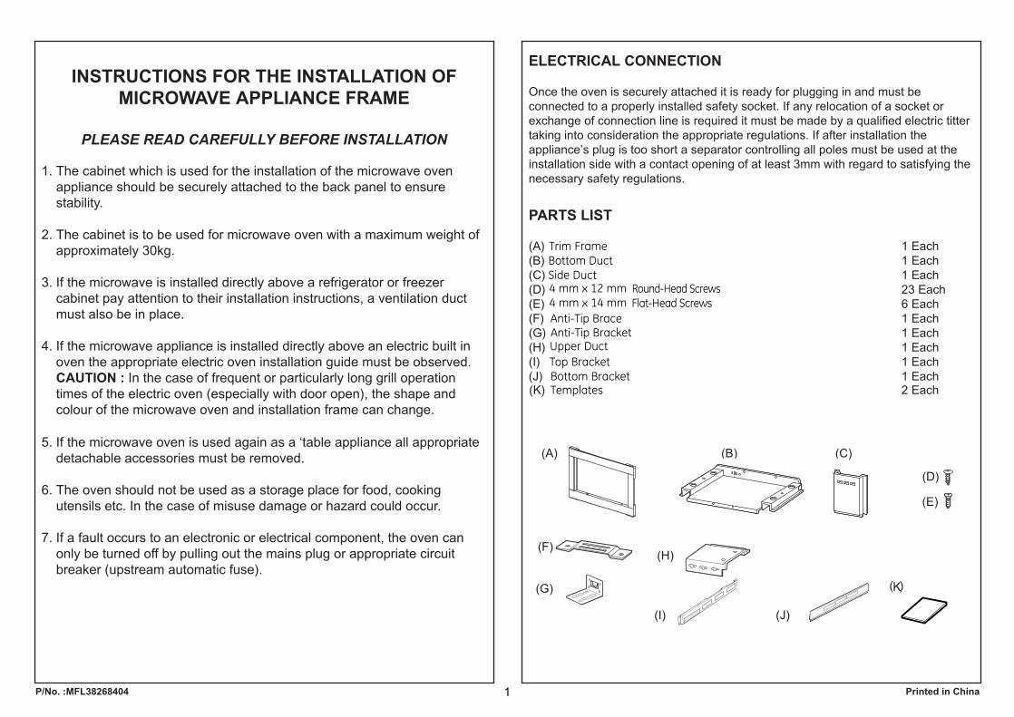
INSTRUCTIONS FOR THE INSTALLATION OF MICROWAVE APPLIANCE FRAME
PLEASE READ CAREFULLY BEFORE INSTALLATION
1. The cabinet which is used for the installation of the microwave ovenappliance should be securely attached to the back panel to ensurestability.
2. The cabinet is to be used for microwave oven with a maximum weight ofapproximately 30kg.
3. If the microwave is installed directly above a refrigerator or freezercabinet pay attention to their installation instructions, a ventilation ductmust also be in place.
4. If the microwave appliance is installed directly above an electric built inoven the appropriate electric oven installation guide must be observed.CAUTION : In the case of frequent or particularly long grill operationtimes of the electric oven (especially with door open), the shape andcolour of the microwave oven and installation frame can change.
5. If the microwave oven is used again as a ‘table appliance all appropriatedetachable accessories must be removed.
6. The oven should not be used as a storage place for food, cookingutensils etc. In the case of misuse damage or hazard could occur.
7. If a fault occurs to an electronic or electrical component, the oven canonly be turned off by pulling out the mains plug or appropriate circuitbreaker (upstream automatic fuse).
ELECTRICAL CONNECTION
Once the oven is securely attached it is ready for plugging in and must beconnected to a properly installed safety socket. If any relocation of a socket orexchange of connection line is required it must be made by a qualified electric tittertaking into consideration the appropriate regulations. If after installation theappliance’s plug is too short a separator controlling all poles must be used at theinstallation side with a contact opening of at least 3mm with regard to satisfying thenecessary safety regulations.
PARTS LIST
(A) 1 Each(B) 1 Each(C) 1 Each(D) 23 Each(E) 6 Each(F) 1 Each(G) 1 Each(H) 1 Each(I) 1 Each(J) 1 Each
P/No. :MFL38268404 Printed in China
Trim FrameBottom DuctSide Duct4 mm x 12 mm Round-Head Screws4 mm x 14 mm Flat-Head Screws
Anti-Tip BracketAnti-Tip Brace
Upper Duct Top BracketBottom Bracket
(K) 2 EachTemplates
1/2 ″down the face of
K
1
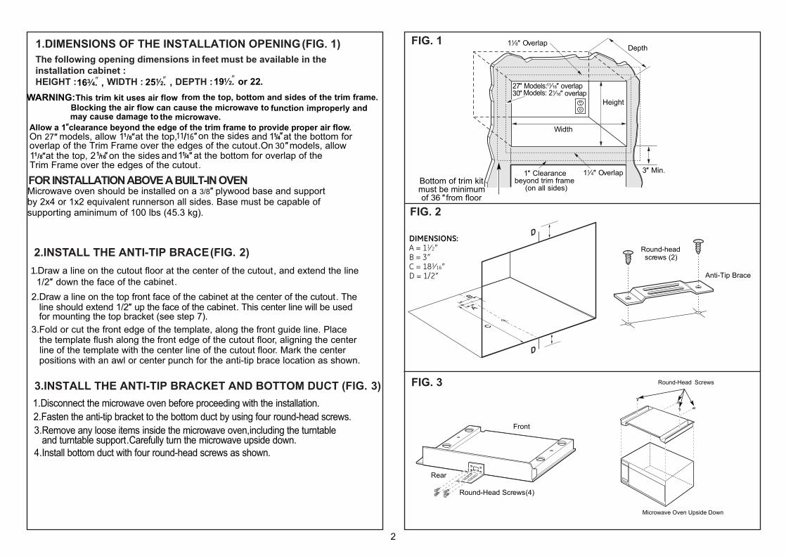
1.Disconnect the microwave oven before proceeding with the installation.2.Fasten the anti-tip bracket to the bottom duct by using four round-head screws.3.Remove any loose items inside the microwave oven,including the turntable and turntable support.Carefully turn the microwave upside down.4.Install bottom duct with four round-head screws as shown.
3.INSTALL THE ANTI-TIP BRACKET AND BOTTOM DUCT (FIG. 3)
(FIG. 2)
(FIG. 1) FIG. 1
FIG. 2
FIG. 3
2.INSTALL THE ANTI-TIP BRACE
FOR INSTALLATION ABOVE A BUILT-IN OVEN
1.DIMENSIONS OF THE INSTALLATION OPENING The following opening dimensions in feet must be available in theinstallation cabinet :HEIGHT : 163⁄ WIDTH : 1 4. , 25 ⁄ 12. , DEPTH :19 ⁄2. or 22.
(FIG 2)
1.Draw a line on the cutout floor at the center of the cutout, and extend the line 1/2 ″ down the face of the cabinet. 2.Draw a line on the top front face of the cabinet at the center of the cutout. The line should extend 1/2″ up the face of the cabinet. This center line will be used
for mounting the top bracket (see step 7). 3.Fold or cut the front edge of the template, along the front guide line. Place the template flush along the front edge of the cutout floor, aligning the center line of the template with the center line of the cutout floor. Mark the center positions with an awl or center punch for the anti-tip brace location as shown.
Depth
Height
11⁄4″ Overlap
Width
11⁄8″ Overlap
1″ Clearancebeyond trim frame
(on all sides)
3″ Min.
27″ Models: 11⁄16″ overlap30″ Models: 21⁄16″ overlap
Bottom of trim kit must be minimum of 36 ″from floor
D
D
Round-head screws (2)
Round-Head Screws
Microwave Oven Upside Down
Anti-Tip Brace
Front
Rear
Round-Head Screws (4)
DIMENSIONS:A = 11⁄ 2″B = 3″C = 183⁄ 16″D = 1/2″
WARNING: This trim kit uses air flow from the top, bottom and sides of the trim frame. Blocking the air flow can cause the microwave to function improperly and may cause damage to the microwave.Allow a 1 clearance beyond the edge of the trim frame to provide proper air flow.On 27 models, allow 11/8 at the top,11 16/ on the sides and 11/4 at the bottom foroverlap of the Trim Frame over the edges of the cutout.On 30″models, allow at the top, 21/16″on the sides and at the bottom for overlap of the Trim Frame over the edges of the cutout.
Microwave oven should be installed on a 3/8″ plywood base and supportby 2x4 or 1x2 equivalent runnerson all sides. Base must be capable of supporting aminimum of 100 lbs (45.3 kg).
″
″ ″ ″
2
″ ″ ″ ″
11/4″11/8″
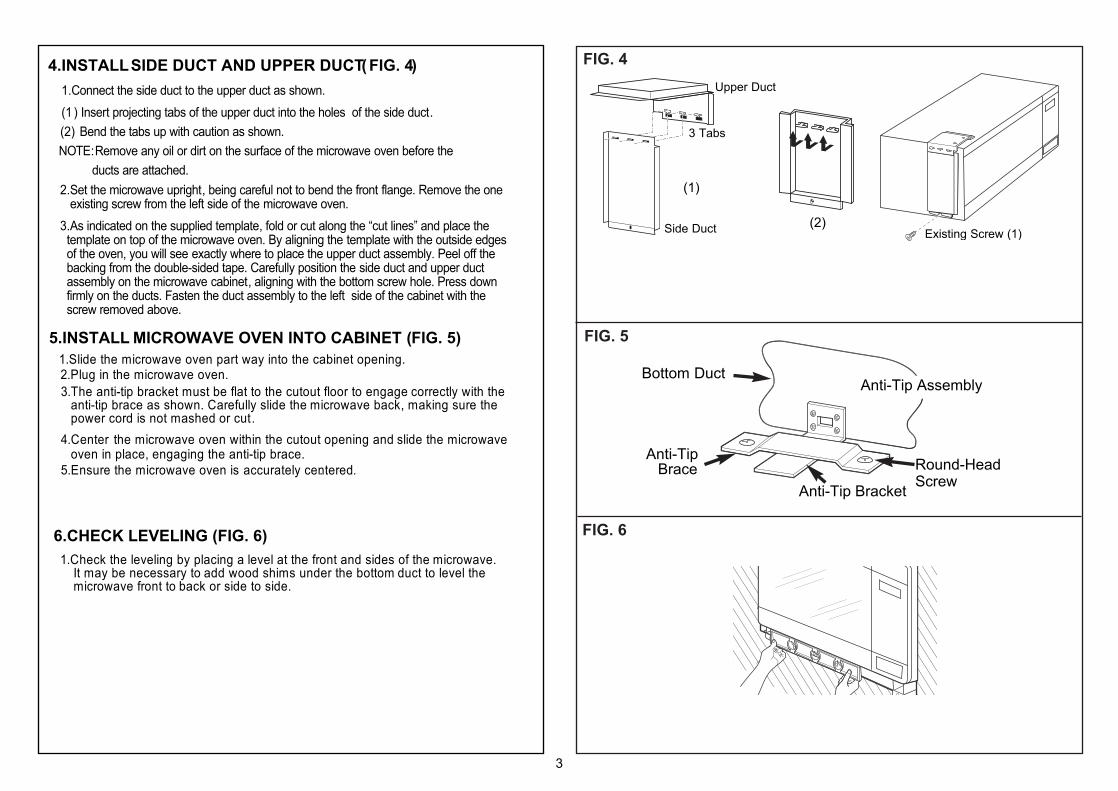
4.INSTALL SIDE DUCT AND UPPER DUCT(FIG. 4)
(FIG. 5)
(FIG. 6)
FIG. 4
FIG. 5
FIG. 6
5.INSTALL MICROWAVE OVEN INTO CABINET
6.CHECK LEVELING Ensure that Top Bracket is Level
Align CenterLines onCabinet andTop Bracket
Mark ScrewHole Locations (also on leftside ofbracket)
Round-HeadScrews
CutoutOpening
Existing Screw (1)(2)
(1)
Upper Duct
Side Duct
3 Tabs
2.Set the microwave upright, being careful not to bend the front flange. Remove the one existing screw from the left side of the microwave oven.3.As indicated on the supplied template, fold or cut along the “cut lines” and place the template on top of the microwave oven. By aligning the template with the outside edges of the oven, you will see exactly where to place the upper duct assembly. Peel off the backing from the double-sided tape. Carefully position the side duct and upper duct assembly on the microwave cabinet, aligning with the bottom screw hole. Press down firmly on the ducts. Fasten the duct assembly to the left side of the cabinet with the screw removed above.
1.Connect the side duct to the upper duct as shown.(1 ) Insert projecting tabs of the upper duct into the holes of the side duct.
(2) Bend the tabs up with caution as shown. NOTE: Remove any oil or dirt on the surface of the microwave oven before the ducts are attached.
1.Slide the microwave oven part way into the cabinet opening.2.Plug in the microwave oven.3.The anti-tip bracket must be flat to the cutout floor to engage correctly with the anti-tip brace as shown. Carefully slide the microwave back, making sure the power cord is not mashed or cut.4.Center the microwave oven within the cutout opening and slide the microwave oven in place, engaging the anti-tip brace.5.Ensure the microwave oven is accurately centered..
1.Check the leveling by placing a level at the front and sides of the microwave. It may be necessary to add wood shims under the bottom duct to level the microwave front to back or side to side.
Anti-Tip AssemblyBottom Duct
Round-HeadScrewAnti-Tip Bracket
Anti-TipBrace
3
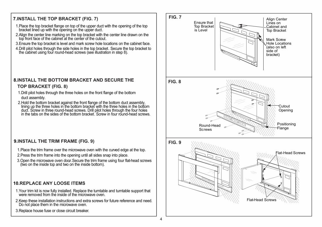
7.INSTALL THE TOP BRACKET (FIG. 7)
(FIG. 8)
(FIG. 9)
FIG. 7
FIG. 8
FIG. 9
Ensure that Top Bracket is Level
Align CenterLines onCabinet andTop Bracket
Mark ScrewHole Locations (also on leftside ofbracket)
Round-HeadScrews
CutoutOpening
Round-HeadScrews
CutoutOpening
PositioningFlange
Flat -Head Screws
Ensure that Top Bracket is Level
Align CenterLines onCabinet andTop Bracket
Mark ScrewHole Locations (also on leftside ofbracket)
1.Place the top bracket flange on top of the upper duct with the opening of the top bracket lined up with the opening on the upper duct.2.Align the center line marking on the top bracket with the center line drawn on the top front face of the cabinet at the center of the cutout.3.Ensure the top bracket is level and mark screw hole locations on the cabinet face.4.Drill pilot holes through the side holes in the top bracket. Secure the top bracket to the cabinet using four round-head screws (see illustration in step 8).
8.INSTALL THE BOTTOM BRACKET AND SECURE THE TOP BRACKET
1.Drill pilot holes through the three holes on the front flange of the bottom duct assembly.2.Hold the bottom bracket against the front flange of the bottom duct assembly, lining up the three holes in the bottom bracket with the three holes in the bottom duct. Screw in three round-head screws. Drill pilot holes through the four holes in the tabs on the sides of the bottom bracket. Screw in four round-head screws.
9.INSTALL THE TRIM FRAME
Place the trim frame over the microwave oven with thecurved edge at the top.Press the trim frame into the opening until all sides snap into place.Open the microwave oven door. Secure the trim frame usingfour flat-head screws (two on the inside top and two on theinside bottom).
1.Place the trim frame over the microwave oven with the curved edge at the top..2.Press the trim frame into the opening until all sides snap into place.3.Open the microwave oven door. .Secure the trim frame using four flat-head screws (two on the inside top and two on the inside bottom).
10.REPLACE ANY LOOSE ITEMS 1.Your trim kit is now fully installed. Replace the turntable and turntable support that were removed from the inside of the microwave oven.2.Keep these installation instructions and extra screws for future reference and need. Do not place them in the microwave oven.3.Replace house fuse or close circuit breaker.
4
Flat -Head Screws
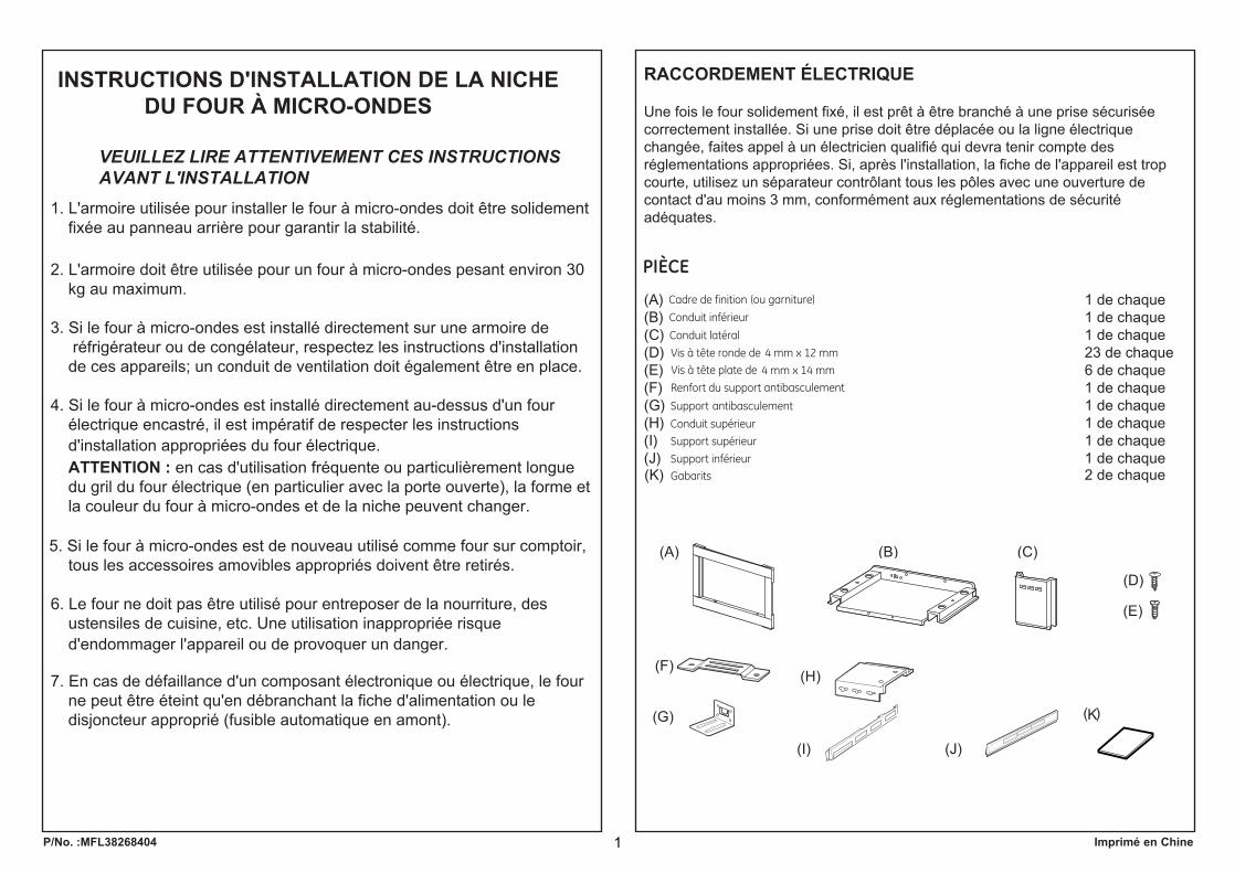
INSTRUCTIONS D'INSTALLATION DE LA NICHE DU FOUR À MICRO-ONDES
VEUILLEZ LIRE ATTENTIVEMENT CES INSTRUCTIONSAVANT L'INSTALLATION
1. L'armoire utilisée pour installer le four à micro-ondes doit être solidement fixée au panneau arrière pour garantir la stabilité.
2. L'armoire doit être utilisée pour un four à micro-ondes pesant environ 30 kg au maximum.
3. Si le four à micro-ondes est installé directement sur une armoire de réfrigérateur ou de congélateur, respectez les instructions d'installation de ces appareils; un conduit de ventilation doit également être en place.
4. Si le four à micro-ondes est installé directement au-dessus d'un four électrique encastré, il est impératif de respecter les instructions d'installation appropriées du four électrique.ATTENTION : en cas d'utilisation fréquente ou particulièrement longue du gril du four électrique (en particulier avec la porte ouverte), la forme et la couleur du four à micro-ondes et de la niche peuvent changer.
5. Si le four à micro-ondes est de nouveau utilisé comme four sur comptoir, tous les accessoires amovibles appropriés doivent être retirés.
6. Le four ne doit pas être utilisé pour entreposer de la nourriture, des ustensiles de cuisine, etc. Une utilisation inappropriée risque d'endommager l'appareil ou de provoquer un danger.
7. En cas de défaillance d'un composant électronique ou électrique, le four ne peut être éteint qu'en débranchant la fiche d'alimentation ou le disjoncteur approprié (fusible automatique en amont).
RACCORDEMENT ÉLECTRIQUE
Une fois le four solidement fixé, il est prêt à être branché à une prise sécurisée correctement installée. Si une prise doit être déplacée ou la ligne électrique changée, faites appel à un électricien qualifié qui devra tenir compte des réglementations appropriées. Si, après l'installation, la fiche de l'appareil est trop courte, utilisez un séparateur contrôlant tous les pôles avec une ouverture de contact d'au moins 3 mm, conformément aux réglementations de sécurité adéquates.
(A) 1 de chaque1 de chaque1 de chaque23 de chaque6 de chaque1 de chaque1 de chaque1 de chaque1 de chaque1 de chaque2 de chaque
(B) (C)(D) (E) (F) (G) (H) (I)(J)
P/No. :MFL38268404 Imprimé en Chine
(K)
1/2 ″down the face of
K
1
Cadre de finition (ou garniture)
Conduit inférieur
Conduit latéral
Vis à tête ronde de 4 mm x 12 mm
Vis à tête plate de 4 mm x 14 mm
Renfort du support antibasculement
Support antibasculement
Conduit supérieur
Support supérieur
Support inférieur
Gabarits
PIÈCE

1. Tracez une ligne sur la surface inférieure e de l’ouverture, au centre de celle-ci et enprolongeant la ligne de 1/2 po sur la partie frontale de l’armoire.
2. Tracez une ligne sur la partie frontale supérieure de l’armoire au centre de l’ouverture. La ligne doit se prolonger de 1/2 po vers le haut sur la partie avant de l’armoire. Cette ligne centrale sera utilisée pour installer le support supérieur (reportez-vous à l’étape 7).
3. Pliez ou découpez le bord avant du gabarit, le long de la ligne de guidage avant. ed erueiréfni ecafrus al ed tnava drob el ceva tnangila’l ne tirabag el zecalP
l’ouverture et en alignant la ligne centrale du gabarit avec la ligne centrale de cette surface inférieure. Marquez les positions centrales de l’emplacement du renfort du support antibasculement avec une alène ou un poinçon comme le montrel’illustration.
2. MONTAGE DU RENFORT DU SUPPORT ANTIBASCULEMENT (FIG. 2)
1. Débranchez le four à micro-ondes avant de passer à l’installation.2. Fixez le support antibasculement au conduit inférieur au moyen de quatre vis à tête
ronde.
3. MONTAGE DU SUPPORT ANTIBASCULEMENT ET DU CONDUIT INFÉRIEUR (FIG. 3)
1. DIMENSIONS DE L'OUVERTURE DE LA NICHE (FIG. 1)L'ouverture doit présenter les dimensions suivantes en pouces dans la niche :HAUTEUR : 16 3/4 po, LARGEUR : 25 1/2 po, PROFONDEUR : 19 1/2 po ou 22.
AVERTISSEMENT:Ce cadre de finition permet à l’air de circuler à partir du haut, du bas et des côtés. Une obstruction de la circulation de l’air peutentraîner un mauvais fonctionnement du four à micro-ondes et l’endommager.
Laissez un espace de 1 po au-delà du bord du cadre de finition pour permettre à l’air de circuler.Sur les modèles de 27 po, laissez 1 po dans la partie supérieure, 11/16 po sur les côtés et 1 1/4 po dans la partie inférieure pour permettre le chevauchement du cadrede finition sur les bords de l’ouverture. Sur les modèles de 30 po, laissez 1 1/8 po dans la partie supérieure, 2 1/16 po sur les côtés et 1 1/4 po dans la partie inférieure pour permettre le chevauchement du cadre de finition sur les bords de l’ouverture.
INSTALLATION AU-DESSUS D’UN FOUR ENCASTRÉ :Le four à micro-ondes doit être installé sur une base en contreplaqué de 3/8 po et être soutenu par des coulisseaux de 2 x 4 po ou des coulisseaux équivalents de 1 x 2 po sur tous les côtés. La base doit pouvoir soutenir une charge minimale de 100 lb (45,3 kg).
1 /8
D
D
Vis à tête ronde
Four micro-ondes tourné à l'envers
Avant
Arrière
Vis à tête ronde (4)
FIG. 1
FIG. 2
FIG. 3
2
Chevauchement de 11/8 po Profondeur
Modèles de 27 po : Chevauch. 11/16 po Modèles de 30 po : Chevauch. 2 1/16 po
Hauteur
Largeur
3 po Espace de 1 po au-delà Chevauchementmin.du cadre de finition (sur de 11/4 po
tous les côtés)La partie inférieure du
cadre de finition doit êtreà au moins 36 po du sol
DIMENSIONS :A = 1 1⁄2 poB = 3 poC =18 3⁄16 poD = 1⁄2 po
Vis à tête ronde (2)
Renfort du supportantibasculement
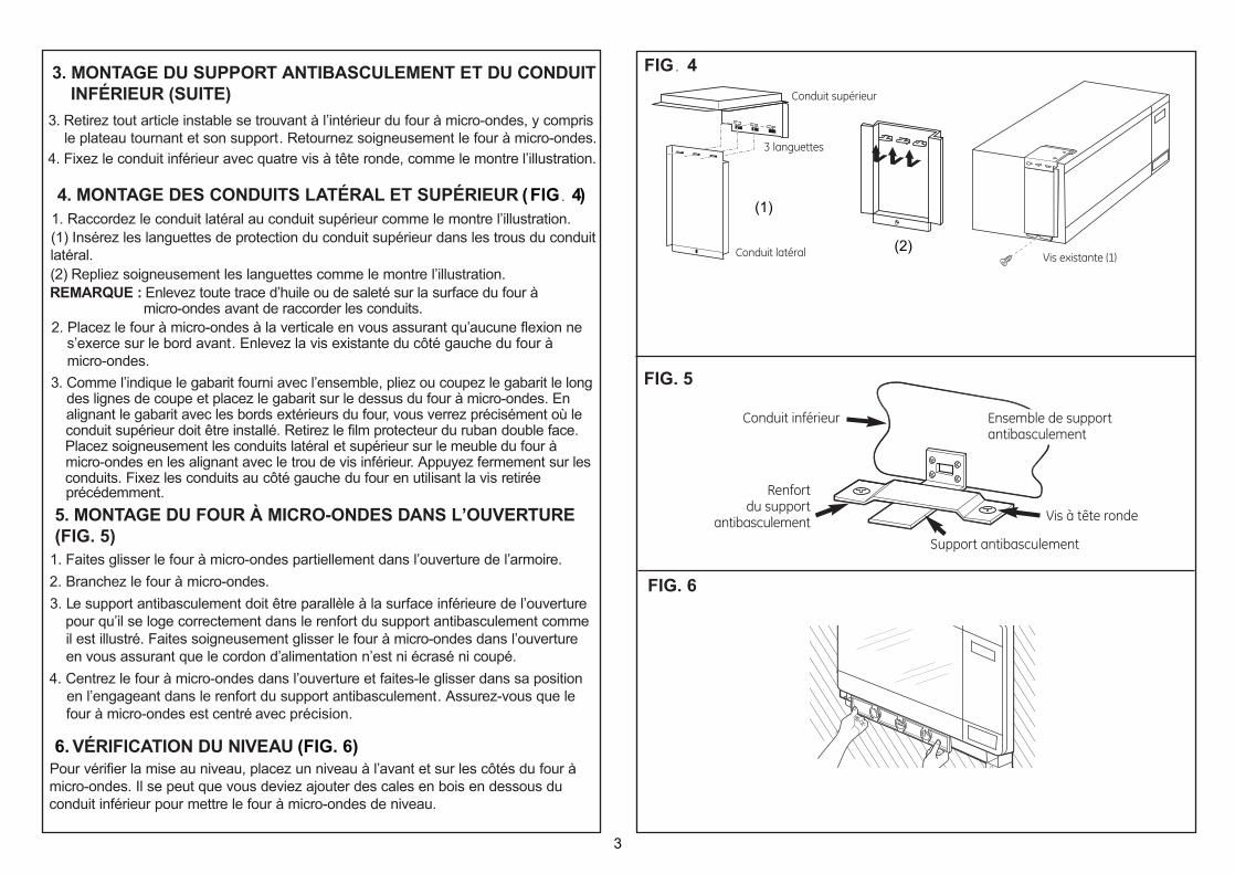
1. Raccordez le conduit latéral au conduit supérieur comme le montre l’illustration.(1) Insérez les languettes de protection du conduit supérieur dans les trous du conduit latéral.(2) Repliez soigneusement les languettes comme le montre l’illustration.REMARQUE : Enlevez toute trace d’huile ou de saleté sur la surface du four à
micro-ondes avant de raccorder les conduits.
4. MONTAGE DES CONDUITS LATÉRAL ET SUPÉRIEUR (FIG 4)
2. Placez le four à micro-ondes à la verticale en vous assurant qu’aucune flexion nes’exerce sur le bord avant. Enlevez la vis existante du côté gauche du four àmicro-ondes.
3. Comme l’indique le gabarit fourni avec l’ensemble, pliez ou coupez le gabarit le long des lignes de coupe et placez le gabarit sur le dessus du four à micro-ondes. En alignant le gabarit avec les bords extérieurs du four, vous verrez précisément où le conduit supérieur doit être installé. Retirez le film protecteur du ruban double face.Placez soigneusement les conduits latéral et supérieur sur le meuble du four à micro-ondes en les alignant avec le trou de vis inférieur. Appuyez fermement sur les conduits. Fixez les conduits au côté gauche du four en utilisant la vis retirée précédemment.
6. VÉRIFICATION DU NIVEAU (FIG. 6)Pour vérifier la mise au niveau, placez un niveau à l’avant et sur les côtés du four à micro-ondes. Il se peut que vous deviez ajouter des cales en bois en dessous du conduit inférieur pour mettre le four à micro-ondes de niveau.
1. Faites glisser le four à micro-ondes partiellement dans l’ouverture de l’armoire.2. Branchez le four à micro-ondes.3. Le support antibasculement doit être parallèle à la surface inférieure de l’ouverture
pour qu’il se loge correctement dans le renfort du support antibasculement comme il est illustré. Faites soigneusement glisser le four à micro-ondes dans l’ouverture en vous assurant que le cordon d’alimentation n’est ni écrasé ni coupé.
4. Centrez le four à micro-ondes dans l’ouverture et faites-le glisser dans sa position en l’engageant dans le renfort du support antibasculement. Assurez-vous que le
précision. cevaértnec tse sedno-orcim à ruof
5. MONTAGE DU FOUR À MICRO-ONDES DANS L’OUVERTURE(FIG. 5)
3. Retirez tout article instable se trouvant à l’intérieur du four à micro-ondes, y comprisle plateau tournant et son support. Retournez soigneusement le four à micro-ondes.
4. Fixez le conduit inférieur avec quatre vis à tête ronde, comme le montre l’illustration.
3. MONTAGE DU SUPPORT ANTIBASCULEMENT ET DU CONDUIT INFÉRIEUR (SUITE)
Ensure that Top Bracket is Level
Align CenterLines onCabinet andTop Bracket
Mark ScrewHole Locations (also on leftside ofbracket)
Round-HeadScrews
CutoutOpening
(2)
(1)
FIG. 4
FIG. 5
FIG. 6
3
Conduit supérieur
Conduit latéral
3 languettes
Vis existante (1)
Conduit inférieur Ensemble de supportantibasculement
Renfort du support
Vis à tête rondeantibasculement
Support antibasculement
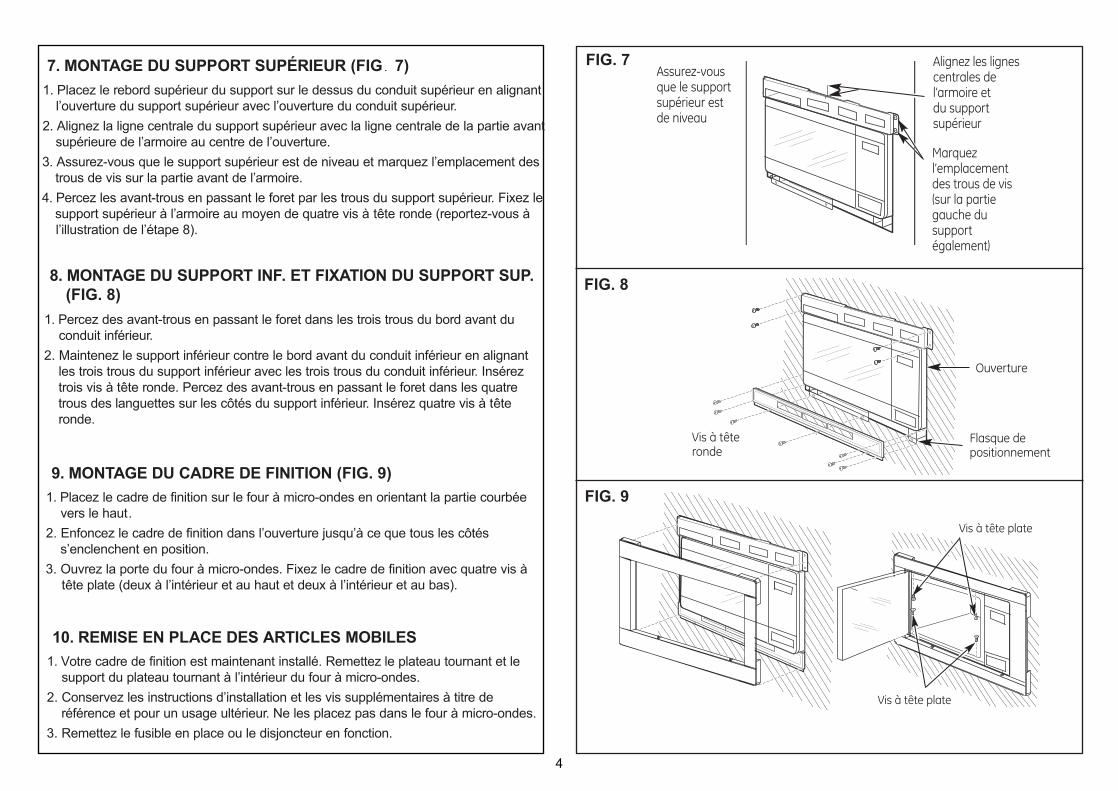
1. Placez le rebord supérieur du support sur le dessus du conduit supérieur en alignantl’ouverture du support supérieur avec l’ouverture du conduit supérieur.
2. Alignez la ligne centrale du support supérieur avec la ligne centrale de la partie avant supérieure de l’armoire au centre de l’ouverture.
3. Assurez-vous que le support supérieur est de niveau et marquez l’emplacement des trous de vis sur la partie avant de l’armoire.
4. Percez les avant-trous en passant le foret par les trous du support supérieur. Fixez le support supérieur à l’armoire au moyen de quatre vis à tête ronde (reportez-vous à l’illustration de l’étape 8).
7. MONTAGE DU SUPPORT SUPÉRIEUR (FIG. 7)
1. Percez des avant-trous en passant le foret dans les trois trous du bord avant duconduit inférieur.
2. Maintenez le support inférieur contre le bord avant du conduit inférieur en alignant les trois trous du support inférieur avec les trois trous du conduit inférieur. Insérez trois vis à tête ronde. Percez des avant-trous en passant le foret dans les quatre trous des languettes sur les côtés du support inférieur. Insérez quatre vis à tête ronde.
8. MONTAGE DU SUPPORT INF. ET FIXATION DU SUPPORT SUP. (FIG. 8)
1. Placez le cadre de finition sur le four à micro-ondes en orientant la partie courbée vers le haut.
2. Enfoncez le cadre de finition dans l’ouverture jusqu’à ce que tous les côtés s’enclenchent en position.
3. Ouvrez la porte du four à micro-ondes. Fixez le cadre de finition avec quatre vis à tête plate (deux à l’intérieur et au haut et deux à l’intérieur et au bas).
9. MONTAGE DU CADRE DE FINITION (FIG. 9)
1. Votre cadre de finition est maintenant installé. Remettez le plateau tournant et le support du plateau tournant à l’intérieur du four à micro-ondes.
2. Conservez les instructions d’installation et les vis supplémentaires à titre de référence et pour un usage ultérieur. Ne les placez pas dans le four à micro-ondes.
3. Remettez le fusible en place ou le disjoncteur en fonction.
10. REMISE EN PLACE DES ARTICLES MOBILES
Ensure that Top Bracket is Level
Align CenterLines onCabinet andTop Bracket
Mark ScrewHole Locations (also on leftside ofbracket)
Round-HeadScrews
CutoutOpening
Place the trim frame over the microwave oven with thecurved edge at the top.Press the trim frame into the opening until all sides snap into place.Open the microwave oven door. Secure the trim frame usingfour flat-head screws (two on the inside top and two on theinside bottom).
FIG. 7
FIG. 8
FIG. 9
4
Assurez-vousque le supportsupérieur estde niveau
Alignez les lignescentrales del’armoire et du supportsupérieur
Marquezl’emplacement des trous de vis(sur la partiegauche dusupportégalement)
Ouverture
Flasque depositionnement
Vis à têteronde
Vis à tête plate
Vis à tête plate