Embed Size (px)
Citation preview
2012BEST PRACTICES
GUIDELINE MANUAL
Revised November, 2011
• INTRODUCTION
• BODY
• CHASSIS
• ELECTRICAL
• PAINT & SEALING
Introduction – Best Practices – 2012
IntroductIon – Best PractIces iPAG
E
A. Objectives ........................................................................................................................................................................................... 1
B. Important: A Word About This Guide ................................................................................................................................................ 1
C. Defining the Guideline Manual ............................................................................................................................................................ 1
D. Upfitter Integration Expectations ........................................................................................................................................................ 2
E. Continuous Improvement .................................................................................................................................................................... 2
F. Key Product Characteristics ............................................................................................................................................................... 2
G. Reference Materials ............................................................................................................................................................................ 3
H. Vehicle Weight ..................................................................................................................................................................................... 3
I. Serviceability ....................................................................................................................................................................................... 4
J. Torque Specifications .......................................................................................................................................................................... 4
K. Special Vehicle Manufacturer's Body ................................................................................................................................................. 4
L. Body Sealing ....................................................................................................................................................................................... 5
M. SVM Responsibility ............................................................................................................................................................................. 5
N. Responsibility for Complete Vehicle Document ................................................................................................................................. 5
O. Incomplete Vehicle Document ............................................................................................................................................................ 6
P. Characteristics of a Compliance Control System .............................................................................................................................. 6
Q. Noise Emission Standards for Transportation Equipment: Medium and Heavy Trucks – 40 CFR Part 205 ............................................................................................................................ 7
R. Federal Regulations – Tires................................................................................................................................................................. 8
S. Personnel and Process Controls ........................................................................................................................................................ 8
T. General Information............................................................................................................................................................................. 9
Index

Introduction – Best Practices – 2012
IntroductIon – Best PractIces 1PAG
E
A. ObjectivesThe objective of the UPFITTER INTEGRATION GROUP is to provide assistance to the Special Vehicle Manufacturer (SVM) to assure that converted, upfitted and modified vehicle quality, reliability and durability meet or exceed the expectations of our mutual customers resulting in total customer satisfaction.
B. Important: A Word About This GuideThis guide is intended for use by RV truck and commercial upfitters with expertise in their field. It, and periodically other support, is offered to assist RV and commercial truck upfitters in converting/completing RV and Commercial Truck vehicles; however, it is not intended to be a complete “how-to” authority, or a substitute for sound engineering and other judgment. The conversion and modification of vehicles requires skills and knowledge not covered in this guide. Neither General Motors, nor their representatives, assume any responsibility for the RV and commercial truck upfitters’ work, including their design, materials, and workmanship.
Please direct technical questions or problems not covered in this manual to the Upfitters Integration Group Hotline (800) 875-4742.
Introduction
C. Defining The Guideline ManualThis Upfitter Integration Best Practices Guideline Manual provides engineering recommendations and guidelines to assist the Special Vehicle Manufacturer (SVM) for all areas of the vehicle affected in the conversion process. The intent is to assure that the finished vehicle meets or exceeds Original Equipment Manufacturer (OEM) quality.
CAUTION
WARNING
The primary focus of the Guideline Manual is the G Van, and C/K Truck. However, most recommendations are generic and can be applied to all GM models that are modified.
The recommendations and guidelines in this manual are based on documented engineering principles and a philosophy of continuous improvement. However, they also take into consideration the other factors that SVMs face, such as, cost, timing, and resource pressure.
The Upfitter Integration group recommends that all SVMs become familiar with this manual and the reference publications listed herein before starting the process. These guidelines stress vehicle safety, quality, reliability and durability. However, each SVM also has the responsibility to:
•Makesurethatvehiclemodificationsdonotreduce the vehicle’s integrity.
•ComplywithallFederal,Stateandlocalregulations.
•Verifythatvehiclesafetyismaintained.
• Meetorexceedtherequirementsandexpectations of the customer.
To simplify the appearance of this manual and make it easier to use, special symbols were created to draw your attention to important information: Please take special note of this information.
Failure to comply may cause damage to the vehicle.
Failure to comply may result in human injury.
This procedure is not recommended.
(continued on next page)

Introduction – Best Practices – 2012
IntroductIon – Best PractIces 2PAG
E
Introduction (cont'd) General Motors Corporation requires confidentiality in the exchange of information with Special Vehicle Manufacturers. General Motors will honor all requests for confidentiality from the SVMs and expects, in return, that all General Motors product information will be treated as confidential material.
(continued on next page)
D. Upfitter Integration ExpectationsThe success of the Upfitter Integration group depends on an atmosphere of communication, cooperation and trust between SVMs and General Motors. Therefore, SVMs are expected to use the Upfitter Integration resources available to them (i.e., telephone hotline, quality surveys, guideline manuals and Upfitter Integration engineering expertise). SVMs are expected to have documented processes which are understood and accepted by all. Documented processes should be in place at work stations, followed explicitly and monitored for effectiveness.
E. Continuous Improvement The Upfitter Integration group expects all SVMs to
establish a company-wide continuous improvement process to focus on achieving and maintaining total customer satisfaction.
A continuous improvement plan should describe the processes SVMs use to implement continuous improvement and the methods used to monitor and evaluate the effectiveness of all processes. Continuous improvement is an ongoing customer-driven process. It enables all personnel in an organization to contribute to achieving the primary business goals of optimizing quality, cost, and delivery while eliminating organizational waste
F. Key Product Characteristics Key product characteristics are the features of a vehicle or system that have the greatest impact on total customer satisfaction. Significant variation in these areas could adversely affect safety, quality, vehicle performance, etc. Typically, key product characteristics can be seen, touched, and felt by customers.
It is the SVM’s responsibility to identify all pertinent key product characteristics.
General Motors encourages all SVMs to use documented processes for guaranteeing that all key product characteristics are maintained on a consistent basis. The process should identify measurable specifications for acceptance/rejection to maintain in-process quality control.Therefore, the SVM should develop processes that both identify and control key product characteristics and also assure vehicle safety, quality, reliability, and durability.
Introduction – Best Practices – 2012
IntroductIon – Best PractIces 3PAG
E
(continued on next page)
Introduction (cont'd)
G. Reference MaterialsThroughout this manual you will see references to the following publications: • FederalMotorVehicleSafetyStandards(FMVSS) and Canada Motor Vehicle Standards (CMVSS) •SocietyofAutomotiveEngineers(SAE) recommended procedures •GeneralMotorsServiceManuals •GeneralMotorsTruckBodyBuildersManual •GeneralMotorsIncompleteVehicleDocument • IndustrialFastenersInstituteStandards (Metric and English) •RVIAHandbook •NTEAPublications •DelphiPackardElectricConnectionSystemsCatalog •DelphiPackardElectricManuals — Product Engineering Handbook — Wire Routing Design Quality Guidelines
H. Vehicle WeightGeneral Motors vehicles are designed to perform effectively within specific total weight and weight distribution ranges. The SVMs must not add weight to the vehicle which would cause the vehicle to exceed GVWR or GAWR.
• GVWR — Gross Vehicle Weight Rating is the total weight of a loaded truck. GVW is found by adding the payload weight to the curb weight of a vehicle. GVWR is the maximum allowable GVW for an individual chassis and body type.
• GAWR — Gross Axle Weight Rating is the maximum allowable GAW for either the front or rear axle.
Modifications resulting in weights which exceed theGVWR or GAWR are not approved by General Motorsand may violate federal certification. If this condition occurs, the SVMs will be required to recertify complianceto all applicable federal regulations. An overweight condition would also have an adverse effect on over-all vehicle performance and customer satisfaction.
Significant variations in vehicle weight and/or distribution could affect the following areas:
Performance to FMVSS/CMVSS requirements
•Occupantsafety
•Centerofgravitylocation
•Brakeperformance
•Frontandrearaxleloads
•Frontandrearspringloads
•Tireloads
•Vehiclehandlingandsteering
One acceptable way to verify compliance to vehicle weight specifications is to weigh each vehicle model before it leaves the SVM’s facility.For more detailed information about weight, refer to the General Motors Truck Body Builders Manual.
WARNING
Introduction – Best Practices – 2012
IntroductIon – Best PractIces 4PAG
E
(continued on next page)
Introduction (cont'd)
I. ServiceabilityServiceability is important to total customer satisfaction.
Ease of serviceability is most important in areas that require regularly scheduled maintenance and will reduce overall warranty expense.
The SVMs can contribute to ease of serviceability in the following ways:
•Payspecialattentiontoregularmaintenanceitems.
•Makesurethatmaintenancecanbeperformedwith common shop tools.
•Keepcriticaladjustmentstoaminimum.
•Provideadequatetoolaccess.
•Provideasimplemethodtodeterminecauseoffailure with a minimum of test equipment.
•Specifyreusablefastenerswherepossible.
•Usecomponentsthatcanberebuilttooriginaldesign specifications.
•Providealigningholes,dimples,orcutoutsonmating flanges for ease of reassembly.
• Includeallrelevantservicedocumentationinthe vehicle’s Owners Manual.
J. Torque Specifications It is the SVM’s responsibility to identify all critical
fasteners and torque specifications. Assemblers should have proper tools and equipment to assure that torque specifications are met. A schedule for tool torque calibration is recommended.
CAUTION
Critical fasteners are defined as those fasteners where loss of function would affect (but not be limited to) the following areas:
•Allregulatoryconformance(Federal, State, local)
•Occupantsafety
• Lossofvehiclecontrol
The SVMs should use a documented quality control process to monitor vehicle assembly. Assembly tools and equipment must be maintained to calibrated specifications. For more information, refer to Appendix II in the Body section of this manual (General Fastener) and the Industrial Fasteners Institute Standards.
K. Special Vehicle Manufacturer's Body •Assure that all required labels that warn, instruct or inform are located on the vehicle where they can be read easily or as required by government regulation.
•Provide the customer with a method of direct contact such as a toll free line.
•Use a customer survey process to measure customer satisfaction.
•Consult legal counsel and FMVSS/CMVSS to determine SVMs’ responsibilities with respect to labeling.
Introduction – Best Practices – 2012
IntroductIon – Best PractIces 5PAG
E
(continued on next page)
Introduction (cont'd)
L. Body Sealing All holes or cutouts in the body must be thoroughly
sealed. Self-sealing fasteners, pumpable sealers or any other approved sealing system should be used to assure that there is no water or carbon monoxide intrusion into the vehicle. See the Upfitter Integration Paint and Sealing Guideline Manual.
M. SVM Responsibility Compliance or implementation of recommendations
in this manual are not to be construed as a substitute for verifying compliance to any federal, state or local regulations. Compliance to all standards remains the responsibility of the SVM as the final stage manufacturer.
General Motors does not take responsibility for the quality of components, methods, materials or workmanship of the SVMs, or against incidents that may result from the conversion of General Motors vehicles.The federal government has established motor vehicle safety standards for various categories of motor vehicles and motor vehicle equipment under the provision of the National Traffic and Motor Vehicle Safety Act of 1966. The Act identifies important legal responsibilities of manufacturers, dealers, body builders, and others engaged in the manufacturing and marketing of motor vehicles and motor vehicle equipment. Questions dealing with the specific application of the Act or the Standards to your own business should be discussed with your legal counsel. This is especially important because standards and other requirements/interpretations are subject to change by the government agency in charge: the National Highway Traffic Safety Administration (NHTSA).
New standards and amendments issued by the National Highway Traffic Safety Administration will appear in the Federal Register from time to time. You may obtain the Federal Register through the Superintendent of Documents, U.S. Government Printing Office, Washington, DC 20402.
It is also the responsibility of the SVM to:
• Assurethatallrequired labels that warn, instruct or inform are located on the vehicle where they can be easily read. Consult legal counsel and the FMVSS/CMVSS to determine SVM responsibility with respect to labeling.
• Providethecustomerwithamethodofdirectcontactsuch as a toll free line.
• Useacustomersurveyprocesstomeasurecustomersatisfaction.
• Maintainacleanandwell-organizedmanufacturingfacility.
• Roadtestvehiclestoexposediscrepanciesinthedesignand build processes.
N. Responsibility For Complete Vehicle PerformanceGeneral Motors performs extensive testing on all vehicles described in this manual. Major changes to a complete vehicle or the installation of a body by an upfitter on an incomplete vehicle chassis will affect vehicle performance. It is the responsibility of the Special Vehicle Manufacturer to validate final completed vehicle performance. Total
vehicle system performance tests may be required. The test schedule must reflect the type of vehicle system conditions to which the completed vehicle will be subjected to and must also include consideration of all aspects of performance, such as durability, ride and handling.
Introduction – Best Practices – 2012
IntroductIon – Best PractIces 6PAG
E
(continued on next page)
Introduction (cont'd)
O. Incomplete Vehicle Document An Incomplete Vehicle Document is supplied with each incomplete vehicle. It provides instructions for intermediate and final stage manufacturers to use in determining conformity to applicable Federal Motor Vehicle Safety Standards (FMVSS). This document also includes instructions which must be followed to assure that EPA and California emission certification requirements are met.In addition, General Motors provides a GM Body BuildersManual for the Special Vehicle Manufacturer to use in the completion of the vehicle. In no case should any SVM alterations affect the function, physical or mechanical properties,environment or vital space clearance of the components,assemblies, or systems of the incomplete vehicle.
The Incomplete Vehicle Document also specifies that the center of gravity location be within certain limits for proper brake balance, and may be more restrictive than the data mentioned above. The SVM must use all appropriate data.
For further assistance, contact General Motors by calling the Upfitter Integration Hotline at 1-800-875-4742 or visit the upfitter web site: www.gmupfitter.com.
P. Characteristics Of A Compliance Control System The following recommendations are suggested as
guidelines for developing a compliance control system: • Assignadesignatedpersontoberesponsibleforthe
interpretation and compliance to FMVSS, CMVSS and other government regulations.
• Useadocumentedprocesstoassurecompliancewith FMVSS and CMVSS regulations. Include a formal analysis in writing with appropriate document signoff.
•KeeponfileintheEngineeringDepartmentaformal engineering change control system, which documents product and process changes.
Perform a design and process PFMEA (Potential Failure Mode Effects and Analysis) on any design modifications made to the OEM cab/chassis to assure reliability and build consistent with all OEM specifications and guidelines.
Perform a weight and balance analysis on each model vehicle to assure compliance to OEM specifications. Never exceed OEM GVWR or GAWR specifications. Refer to the “Incomplete Vehicle Document” section for additional data. The significant elements for weight and balance analysis are:
— OEM base vehicle
— SVM conversion (including all permanently attached equipment)
— All fluids (at full levels) required to operate the vehicle
— Occupant (driver and all other belted positions weights
— Maximum cargo capacity
• Providemanufacturingandassemblypersonnelwith engineering drawings and assembly procedures.
WARNING
Introduction – Best Practices – 2012
IntroductIon – Best PractIces 7PAG
E
• Use a final inspection process and include the documented results with the vehicle records. The results should have clear accept/reject criteria, and should include the following systems:
— Engine cooling
— Engine and transmission performance, including downshiftandPRNDLindexing
— High idle RPM setting and full throttle pedal travel
— Fuel system leaks
— Exhaust shielding and leaks
— Body/cab leaks
— Electrical performance
— Brake performance
— Parking brake performance
— Ride/handling/steering
— Vehicle vibrations and noise
— Heater/air conditioning function and leak test
— A/C recharge capacity labels
— Paint code
(continued on next page)
Introduction (cont'd)
P. Characteristics Of A Compliance Control System (continued)
Q. Noise Emission Standards For Transportation Equipment: Medium and Heavy Trucks – 40CFR Part 205
The U.S. Environmental Protection Agency (EPA) has established noise emission standards applicable to vehicles manufactured after January 1, 1978, under the provisions of the Noise Control Act of 1972 (in general, vehicles in excess of 10,000 pounds GVWR capable of transportation of property on a street or highway). The standard providesthat vehicles manufactured after January 1, 1988, must conform to a maximum 80 dBA level.
The Act and the standards impose legal obligations on vehicle manufacturers and subsequent manufacturers. Questions about the standard’s definition of a “vehicle” or the specific application of the Act or its standards to your own business should be discussed with your legal counsel. This is especially important because of the EPA’s broad definitionof a “vehicle”.
Standards or interpretations of such standards are subject to change by the EPA. New standards or amendments issued by the Environmental Protection Agency appear in the Federal Register from time to time. You may obtain the Federal Register through the Superintendent of Documents, U.S.Government Printing Office, Washington, DC 20402.
Introduction – Best Practices – 2012
IntroductIon – Best PractIces 8PAG
E
(continued on next page)
Introduction (cont'd)
R. Federal Regulations – TiresThe National Highway Traffic Safety Administration has issued regulations dealing with tire identification and record keeping which became effective May 22, 1971. Under these regulations important legal responsibilities are imposed upontire manufacturers, brand name owners, retreaders,distributors and dealers, and motor vehicle manufacturers and dealers, to maintain and/or report certain information concerning tires. This information will be used to facilitate interest of safety. If you have any questions concerning theapplication of these regulations to your business, we suggest you consult with your legal counsel.
In order for General Motors to meet its responsibility under these tire regulations we have a record of the tires on each vehicle we shipped to you. If you do not change a tire on a General Motors vehicle, it is important that you make sure that it is reshipped with the same tires that were on it whenthe vehicle was received by you. This means that any tire which you remove from a vehicle during the course of your work should be put back on the same vehicle.
If you replace a tire on a General Motors vehicle, you are responsible for maintaining records of the vehicle identification number (VIN) and the vehicle owner to allow notification, through your records, if tire problems are found.
In case you should receive a defect notification from a tire manufacturer concerning tires which you installed on a vehicle returned to us, you may forward it to us so that we can send it to the vehicle owner whose name will appear on our records.
S. Personnel And Process ControlsThe General Motors vehicle systems are highly complex in their operation and componentry, and extremely sensitive to SVM alterations and/or additions. Therefore, to assure vehicle system quality in every vehicle, a climate of constant and careful attention to processing details must be established.Doing so will aid in the production of problem free vehicles, the promotion of customer satisfaction and reduction of warranty expense.
General Motors recommends that all personnel involved in the design, installation and testing of the vehicle systems thoroughly understand the information contained in this manual. Additionally, it is suggested that the SVM adopt the practices and procedures described in this manual andappoint a qualified individual to coordinate all activities related to the processing of the vehicle systems.
Ideally, the SVM’s vehicle coordinator would have a combination of technical, communication and administrative skills that would enable him/her to perform several important functions. These functions would include implementing, monitoring and controlling all vehicle processes includingassembly, installation, repair, maintenance, quality control and evaluation; identifying problems and recommending solutions; coordinating activities between departments and groups; gathering, interpreting and disseminating necessary technical and administrative data and other information.
Introduction – Best Practices – 2012
IntroductIon – Best PractIces 9PAG
E
T. General Information In the event the reader should conclude that the General
Motors recommendations in this manual conflict with the ANSI/RVIA standards or with any recommendations
and/or directions furnished with any components that the SVM installs, the SVM should contact the General Motors Upfitter Integration group for clarification and/or guidance. (1-800-875-4742).
No recommendations in this manual knowingly conflict with any FMVSS, CMVSS, state and/or local regulations. In the event it is deemed there may be a conflict, the federal, state and/or local regulations shall take precedence.
The guidelines and information in this manual are not intended to supplant any standards, instructions, requirements, directions, etc., that are included in the following General Motors documents and/or manuals: • Incomplete Vehicle Document • GM Body Builders Manual(s) •Service Manual(s) •Driveability, Emissions and Electrical Diagnosis Manual(s)
In the event the reader should conclude that there is a conflict, the information contained in the above documents shall take precedence.
It is the SVM’s responsibility to maintain the structural integrity of the OEM vehicle body. To assure this, SVMs should conduct appropriate testing and engineering analyses when modifying any structure of the vehicle’s body.
WARNING
Introduction (cont'd)
Vehicle Body – Best Practices – 2012
Vehicle Body – Best Practices iPAG
E
BODY STRUCTURE �������������������������������������������������������������������������������������������������������������������������������������������������������������������������������������� 1 Window Cutouts ������������������������������������������������������������������������������������������������������������������������������������������������������������������������������������� 1 Side Wall Structure ��������������������������������������������������������������������������������������������������������������������������������������������������������������������������������� 2 Roof Structure ����������������������������������������������������������������������������������������������������������������������������������������������������������������������������������������� 2 Floorpan �������������������������������������������������������������������������������������������������������������������������������������������������������������������������������������������������� 3
WEATHERSTRIPPING ����������������������������������������������������������������������������������������������������������������������������������������������������������������������������������� 4 Weatherstrip Installation ������������������������������������������������������������������������������������������������������������������������������������������������������������������������� 4 Weatherstrip Inspection Process ������������������������������������������������������������������������������������������������������������������������������������������������������������ 5
BODY EXTERIOR COMPONENTS ��������������������������������������������������������������������������������������������������������������������������������������������������������������� 5 Ladders, Spare Tire Carriers and Luggage Racks ��������������������������������������������������������������������������������������������������������������������������������� 5 Lower Body Treatments �������������������������������������������������������������������������������������������������������������������������������������������������������������������������� 6 Running Boards �������������������������������������������������������������������������������������������������������������������������������������������������������������������������������������� 6
BODY INTERIOR COMPONENTS ���������������������������������������������������������������������������������������������������������������������������������������������������������������� 7 Headliner System ������������������������������������������������������������������������������������������������������������������������������������������������������������������������������������ 7 Sun Visors ����������������������������������������������������������������������������������������������������������������������������������������������������������������������������������������������� 7 Floor Covering ���������������������������������������������������������������������������������������������������������������������������������������������������������������������������������������� 8 Carpeting ���������������������������������������������������������������������������������������������������������������������������������������������������������������������������������������� 8 Sound Absorber and Deadener ����������������������������������������������������������������������������������������������������������������������������������������������������� 8 Interior Trim Panels ��������������������������������������������������������������������������������������������������������������������������������������������������������������������������������� 8 Plastic Trim Components ��������������������������������������������������������������������������������������������������������������������������������������������������������������� 8 Wood Trim Components����������������������������������������������������������������������������������������������������������������������������������������������������������������� 8
RESTRAINTS AND SEAT ASSEMBLIES ������������������������������������������������������������������������������������������������������������������������������������������������������ 9 Installation/Torque Specifications ����������������������������������������������������������������������������������������������������������������������������������������������������������� 9
Index
(continued on next page)

Vehicle Body – Best Practices – 2012
Vehicle Body – Best Practices iiPAG
E
FASTENERS ������������������������������������������������������������������������������������������������������������������������������������������������������������������������������������������������� 10 Metal Fasteners ������������������������������������������������������������������������������������������������������������������������������������������������������������������������������������ 10 Plastic Fasteners ���������������������������������������������������������������������������������������������������������������������������������������������������������������������������������� 11 Squeaks and Rattles ����������������������������������������������������������������������������������������������������������������������������������������������������������������������������� 11
APPENDIX I �������������������������������������������������������������������������������������������������������������������������������������������������������������������������������������������������� 12 Welding Guidelines and Precautions ���������������������������������������������������������������������������������������������������������������������������������������������������� 12 Welding Precautions ����������������������������������������������������������������������������������������������������������������������������������������������������������������������������� 12 Electrical System �������������������������������������������������������������������������������������������������������������������������������������������������������������������������� 13
APPENDIX II ������������������������������������������������������������������������������������������������������������������������������������������������������������������������������������������������� 14 General Fastener ���������������������������������������������������������������������������������������������������������������������������������������������������������������������������������� 14 Reference �������������������������������������������������������������������������������������������������������������������������������������������������������������������������������������� 14 Fastening to Thin Sheet Metal ������������������������������������������������������������������������������������������������������������������������������������������������������������� 14
APPENDIX III ������������������������������������������������������������������������������������������������������������������������������������������������������������������������������������������������ 22 Design Principles to Eliminate Squeak & Rattle Reference ����������������������������������������������������������������������������������������������������������������� 22 Squeak & Rattle-Free Design Checklist ��������������������������������������������������������������������������������������������������������������������������������������� 22 General Principles ������������������������������������������������������������������������������������������������������������������������������������������������������������������������ 22 Instrument Panel & Dash �������������������������������������������������������������������������������������������������������������������������������������������������������������� 26 Electrical �������������������������������������������������������������������������������������������������������������������������������������������������������������������������������������� 36 Interior Trim ����������������������������������������������������������������������������������������������������������������������������������������������������������������������������������� 41 Body & Exterior Trim ��������������������������������������������������������������������������������������������������������������������������������������������������������������������� 44 Seat & Seat Belt ��������������������������������������������������������������������������������������������������������������������������������������������������������������������������� 47
Index

Vehicle Body – Best Practices – 2012
Vehicle Body – Best Practices 1PAG
E
Body – Structure
Window CutoutsWhen installing additional windows during the conversion process, it is important to implement practices that will not compromise the quality of the OEM vehicle. Additionally, standard procedures help to obtain consistent results. General Motors recommends the following:
Use templates and fixtures when locating side windows. Use pre-existing features, such as the drip rail or body opening line, as reference points to locate templates and fixtures. (See Figures 1 and 2.)
Figure 1
• Whenpreparingrawmetaledges,eliminateallsharpedgessometal preservative will adhere properly (Figure 3). Apply rust inhibitor around all body cutouts and holes drilled through exterior painted body panels. See the Upfitter Integration Paint and Sealing Guideline Manual.
Figure 2
Figure 3
MICROSCOPIC EDGE VIEWS

Vehicle Body – Best Practices – 2012
Vehicle Body – Best Practices 2PAG
E
Side Wall StructureIt is necessary to assure that the strength of the modified sidewall structure is equal to or greater than that supplied with the OEM vehicle.
Install additional structures by bolting or welding them to the basic members of the body structure such as the roof rail, floor pan, wheel house, pillars or horizontal and vertical strainers.
Refer to the Appendix I for general welding guidelines.
Body – Structure (cont'd) •Withahigh-poweredvacuumremoveallmetaldebris|
(i.e., chips, ribbons, slivers, etc.) from the interior of the vehicle. This process eliminates potential damage to electrical wires and moving parts. It also helps to prevent premature rusting of the vehicle body.
• Whenaddingexteriorcomponents,chooseonlythosemade of non-corrosive or properly plated materials.
Also, consider the corrosive effect of mating dissimilar metals when selecting materials. (See Paint manual for specific metal corrosion recommendations.)
Conduct water testing to check for any leaks between the newly installed windows and the body, which may occur from the conversion process.
Consult the Incomplete Vehicle Document for recommended locations for installing side body windows.
CAUTION
All SVM-installed window and sunroof glass must meet FVMSS and appropriate state regulations, including those governing the use of shaded glass. Certification markings for any upfitter-installed glass must be visible on the vehicle. The SVM is responsible for recertifying the vehicle when installing non-OEM glass.
WARNING
CAUTION
For electrical system welding precautions, see the Upfitter Integration Electrical Guideline Manual — Electrical System Precautions section.
CAUTION
Roof StructureGeneral Motors recommends the following guidelines for modifying G-Van and M/L Van roof structures (see the incomplete vehicle document):
• Whenaddingaraisedroof,donotremovetheOEMroofstructure forward of the B-pillar.
• Tomaintaincross-bodystability,donotremovethelastroofcrossbow forward of the D-pillar.
Replace the original roof and roof bows only with structures of equal or greater strength.
• Beforeinstallinginteriortrim,conductawatertesttoassurethat there are no roof to body leaks.
Refer to the Incomplete Vehicle Document for guidelines on excessive roof console vertical heights which will obscure the vision through the rearview mirror.
CAUTION
WARNING
Vehicle Body – Best Practices – 2012
Vehicle Body – Best Practices 3PAG
E
Some conversion procedures require perforating or otherwise modifying the floorpan. Use extreme caution when working near fuel lines, fuel tank, exhaust system, heat shields and moving chassis parts.
Use templates to accurately locate holes and drill stops to limit the drilling depth.
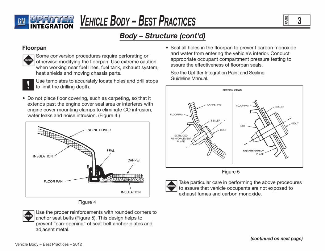
• Donotplacefloorcovering,suchascarpeting,sothatitextends past the engine cover seal area or interferes with engine cover mounting clamps to eliminate CO intrusion, water leaks and noise intrusion. (Figure 4.)
Body – Structure (cont'd)
Floorpan
CAUTION
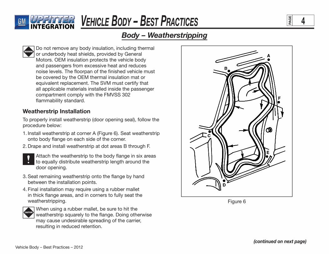
Use the proper reinforcements with rounded corners to anchor seat belts (Figure 5). This design helps to prevent “can-opening” of seat belt anchor plates and adjacent metal.
WARNING
Figure 4
• Sealallholesinthefloorpantopreventcarbonmonoxideand water from entering the vehicle’s interior. Conduct appropriate occupant compartment pressure testing to assure the effectiveness of floorpan seals.
See the Upfitter Integration Paint and Sealing Guideline Manual.
Figure 5
WARNINGTake particular care in performing the above procedures to assure that vehicle occupants are not exposed to exhaust fumes and carbon monoxide.
(continued on next page)
Vehicle Body – Best Practices – 2012
Vehicle Body – Best Practices 4PAG
E
Body – Weatherstripping
CAUTION
Do not remove any body insulation, including thermal or underbody heat shields, provided by General Motors. OEM insulation protects the vehicle body and passengers from excessive heat and reduces noise levels. The floorpan of the finished vehicle must be covered by the OEM thermal insulation mat or equivalent replacement. The SVM must certify that all applicable materials installed inside the passenger compartment comply with the FMVSS 302 flammability standard.
WARNING
Weatherstrip InstallationTo properly install weatherstrip (door opening seal), follow the procedure below:
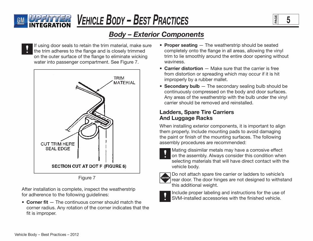
1. Install weatherstrip at corner A (Figure 6). Seat weatherstrip onto body flange on each side of the corner.
2. Drape and install weatherstrip at dot areas B through F.
Attach the weatherstrip to the body flange in six areas to equally distribute weatherstrip length around the door opening.
Figure 6
3. Seat remaining weatherstrip onto the flange by hand between the installation points.
4. Final installation may require using a rubber mallet in thick flange areas, and in corners to fully seat the weatherstripping.
When using a rubber mallet, be sure to hit the weatherstrip squarely to the flange. Doing otherwise may cause undesirable spreading of the carrier, resulting in reduced retention.
(continued on next page)
Vehicle Body – Best Practices – 2012
Vehicle Body – Best Practices 5PAG
E
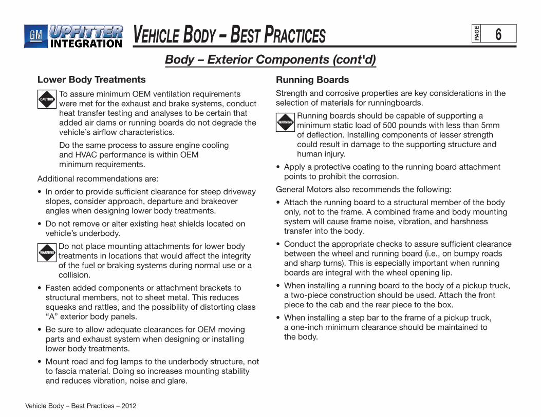
Body – Exterior ComponentsIf using door seals to retain the trim material, make sure the trim adheres to the flange and is closely trimmed on the outer surface of the flange to eliminate wicking water into passenger compartment. See Figure 7.
Figure 7
After installation is complete, inspect the weatherstripfor adherence to the following guidelines:
• Corner fit — The continuous corner should match the corner radius. Any rotation of the corner indicates that the fit is improper.
• Proper seating — The weatherstrip should be seated completely onto the flange in all areas, allowing the vinyl trim to lie smoothly around the entire door opening without waviness.
• Carrier distortion — Make sure that the carrier is free from distortion or spreading which may occur if it is hit improperly by a rubber mallet.
• Secondary bulb — The secondary sealing bulb should be continuously compressed on the body and door surfaces. Any areas of the weatherstrip with the bulb under the vinyl carrier should be removed and reinstalled.
Ladders, Spare Tire Carriers And Luggage RacksWhen installing exterior components, it is important to align them properly. Include mounting pads to avoid damaging the paint or finish of the mounting surfaces. The following assembly procedures are recommended:
Mating dissimilar metals may have a corrosive effect on the assembly. Always consider this condition when selecting materials that will have direct contact with the vehicle body.
Do not attach spare tire carrier or ladders to vehicle’s rear door. The door hinges are not designed to withstand this additional weight.
Include proper labeling and instructions for the use of SVM-installed accessories with the finished vehicle.
CAUTION
Vehicle Body – Best Practices – 2012
Vehicle Body – Best Practices 6PAG
E
Body – Exterior Components (cont'd)
Lower Body Treatments
CAUTIONTo assure minimum OEM ventilation requirements were met for the exhaust and brake systems, conduct heat transfer testing and analyses to be certain that added air dams or running boards do not degrade the vehicle’s airflow characteristics.
Do the same process to assure engine coolingand HVAC performance is within OEMminimum requirements.
Additional recommendations are:
• Inordertoprovidesufficientclearanceforsteepdrivewayslopes, consider approach, departure and brakeover angles when designing lower body treatments.
• Donotremoveoralterexistingheatshieldslocatedonvehicle’s underbody.
Do not place mounting attachments for lower body treatments in locations that would affect the integrity of the fuel or braking systems during normal use or a collision.
• Fastenaddedcomponentsorattachmentbracketstostructural members, not to sheet metal. This reduces squeaks and rattles, and the possibility of distorting class “A” exterior body panels.
• BesuretoallowadequateclearancesforOEMmovingparts and exhaust system when designing or installing lower body treatments.
• Mountroadandfoglampstotheunderbodystructure,notto fascia material. Doing so increases mounting stability and reduces vibration, noise and glare.
WARNING
Running BoardsStrength and corrosive properties are key considerations in the selection of materials for runningboards.
Running boards should be capable of supporting a minimum static load of 500 pounds with less than 5mm of deflection. Installing components of lesser strength could result in damage to the supporting structure and human injury.
• Applyaprotectivecoatingtotherunningboardattachmentpoints to prohibit the corrosion.
General Motors also recommends the following:
• Attachtherunningboardtoastructuralmemberofthebodyonly, not to the frame. A combined frame and body mounting system will cause frame noise, vibration, and harshness transfer into the body.
• Conducttheappropriatecheckstoassuresufficientclearancebetween the wheel and running board (i.e., on bumpy roads and sharp turns). This is especially important when running boards are integral with the wheel opening lip.
• Wheninstallingarunningboardtothebodyofapickuptruck,a two-piece construction should be used. Attach the front piece to the cab and the rear piece to the box.
• Wheninstallingastepbartotheframeofapickuptruck, a one-inch minimum clearance should be maintained to
the body.
WARNING
Vehicle Body – Best Practices – 2012
Vehicle Body – Best Practices 7PAG
E
Body – Interior Components
WARNING
WARNING
The purpose of added interior components is twofold: to provide occupant convenience as well as a visually appealing environment.
It is the SVM’s responsibility to assure that all added interior components comply with FMVSS standards 201 (occupant protection in interior impact) and 302 (flammability of interior materials).
Additional recommendations are:
• Attachallload-bearinginteriorhardwaretothebodystructure to assure mounting strength.
• Donotinstallcomponentswithsharpedgesorprotrusionsthat may potentially harm vehicle occupants.
The minimum radius for corners on interior components is 3.2mm (International Standard).
• Considertherangeofhandandfingermotionwhendesigning and selecting locations for passenger convenience items.
• Aimaddedinteriorlightingforoptimumpassengerconvenience, maximum lighting effectiveness and to avoid disturbing the driver’s vision.
• Includemaintenanceandoperatinginstructionsforalladded interior components with the finished vehicle.
For information on practices recommended by the Society of Automotive Engineers, refer to SAE documents J1048 (Symbols for Motor Vehicle Controls, Indicators and Tell-Tales) and J1139 (Driver Hand Control Locations for Passenger Cars).
Headliner SystemThe headliner system is a high visibility item and must meet or exceed all customer expectations for fit, finish, function and quality. As previously noted, headliner systems must conform to FMVSS standards 201 and 302 for occupant safety and flammability. General Motors expects SVMs to implement processes that guarantee product consistency and those that drive continuous improvement.
• ThedesignshouldavoidgapsbetweentheheadlinerandB-pillar and C-pillar garnish moldings, and roof garnish moldings.
• Toassuremountingintegrity,attachallloadbearing interior hardware (e.g., overhead console) to sheet metal that is well supported.
Avoid placing hidden sharp edges between the headliner and the roof panel. Doing so may result in injury to passengers and damage to the headliner.
Headliner system components should be serviceable without damage to the headliner. Refer to GM service manuals for recommended disassembly procedures.
General Motors recommends using the OEM visors in the upfitted vehicle. SVMs may, however, retrim the original visor to match the vehicle’s interior. Sun visors must comply with FMVSS 101, 201 and 302. Be sure to add appropriate label to sunshades.
Refer to GM Specification 2746M for materials suitable for retrimming the sun visor.
Sun Visors

Vehicle Body – Best Practices – 2012
Vehicle Body – Best Practices 8PAG
E
Body – Interior Components (cont'd)
The floor covering system, which consists of carpeting, absorber and deadener material, must conform to FMVSS 302 (flammability of interior materials).
CarpetingInstall carpeting with a minimum weight of 18 oz. (i.e., 18 oz. Twilight). The minimum thickness for adequate carpet retention is 0.8" (20mm).Choose carpeting that is free of loose threads, wrinkles, bubbles, frayed edges or attachment depressions. Also select materials that will lie flat against mating surfaces. Use only adhesives that are compatible with mating parts.
Sound Absorber and DeadenerInstall sound-absorbing material wherever floorcarpeting is added to a conversion vehicle.
• Useaninsulator(deadener)withasufficientthermalratingwhen it is exposed to higher exhaust system temperatures (see GM Specification 2714M).
• Useathermalcottonsoundabsorbertoenhanceinterioracoustics (see GM Specification 2213M).
Floor Covering
Interior Trim PanelsInterior trim panels serve three important functions:
• Providescloseoutforstructuralpanels
• Securesotherinteriorcomponents
• Enhancesthevehicle’sinteriorstyling
Modifications should conform to the restrictions shown in “Incomplete Vehicle Document” in order to meet FMVSS occupant performance requirements. Like other interior components, trim panels must meet FMVSS standards governing flammability (FMVSS 302).
Upfitters should also reference FMVSS 201, “Occupant Protection in Interior Impacts” for direction concerning interior fittings.
WARNING
Select plastic trim that is free of burrs, flash, mold-parting lines and sink marks. If plastic trim is grained, match the grade and grain direction of the components that are related to it.
Wood Trim Components
Round all wood-trim corners to eliminate sharp edges or protrusions that may result in passenger injury. The minimum radius for interior trim corners is 3.2mm.
Avoid installing wood trim in areas exposed to direct sunlight. Over time, the sun’s ultraviolet rays will degrade the finish of the wood. All SVM-added decorative wood components should conform to GM Specification 2210M.
Plastic Trim Components
WARNING
Vehicle Body – Best Practices – 2012
Vehicle Body – Best Practices 9PAG
E
Body – Restraints and Seat AssembliesSeating components and restraint systems must comply with all applicable FMVSS standards (FMVSS 201, 202, 207, 208, 209, 210, 302). Refer to the Incomplete Vehicle Document for additional information and requirements related to the systems and components discussed in this section.
The OEM restraint systems are designed to function properly with seating reference points and seat travel of the original equipment seats only. The non-OEM seats and belt systems that are installed by the SVM must be certified for complianceto FMVSS and CMVSS regulations.
Installation/Torque Specifications To assure compliance to federal regulations, torque all
added seat and seat belt fasteners to specification.
Avoid altering shoulder belt attachment zones (location and the surrounding structure). Such modifications require FMVSS recertification.
Additional precautions:
• Fordriverandfrontpassengerseatsandbelts
Place seating reference points in locations identical to those specified in the “Incomplete Vehicle Document.”
— If, for any reason, it is necessary to remove OEM factory-installed front seat belts, reinstall them in their original positions using the proper tools. Torque all bolts to specification (see “Incomplete Vehicle Document”).
When drilling fastener holes through the floorpan, make sure that the fuel tank or fuel lines are not contacted. Use drill stops.
— Properly reinforce the floorpan at all fastener locations to avoid pull-through.
— Install backup washers under nuts at all locations.
Do not attach seat pedestals or seat belts through a layer of mat or carpeting. Doing so will cause compression of the material and result in a loss of torque.
All seat belt fasteners must be certified for compliance with FMVSS requirements.
WARNING
WARNING
WARNING
WARNING
Vehicle Body – Best Practices – 2012
Vehicle Body – Best Practices 10PAG
E
Body – FastenersThe term “fastener” refers to bolts, nuts, washers, screws, rivets, pins, staples and other commonly used attaching parts. Most fasteners are metric, but are very close in dimension to common Englishsystem fasteners. Consideration should be given to the full range of available fasteners to assure the appropriate selection. This will help to reduce problems with squeaks, rattles, corrosion, fit and cosmetic appearance.
Metal Fasteners Always use fasteners that match the correct nominal
diameter, thread pitch and strength of the mating part.
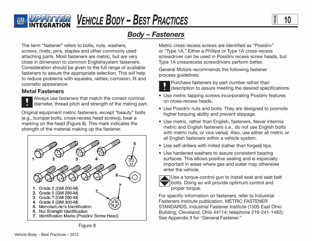
Original equipment metric fasteners, except “beauty” bolts (e.g., bumper bolts, cross-recess head screws), bear a marking on the head (Figure 8). This mark indicates the strength of the material making up the fastener.
Figure 8
Metric cross-recess screws are identified as “Posidriv” or “Type 1A.” Either a Phillips or Type 1A cross-recess screwdriver can be used in Posidriv recess screw heads, but Type 1A crossrecess screwdrivers perform better.
General Motors recommends the following fastener process guidelines:
Purchase fasteners by part number rather than description to assure meeting the desired specifications.
• Use metric tapping screws incorporating Posidriv features on cross-recess heads.
• Use Posidriv nuts and bolts. They are designed to promote higher torquing ability and prevent slippage.
• Use metric, rather than English, fasteners. Never intermix metric and English fasteners (i.e., do not use English bolts with metric nuts, or vice versa). Also, use either all metric or all English fasteners within a vehicle system.
• Use self-drillers with milled (rather than forged) tips.
• Use hardened washers to assure consistent bearing surfaces. This allows positive sealing and is especially important in areas where gas and water may otherwise enter the vehicle.
Use a torque-control gun to install seat and seat belt bolts. Doing so will provide optimum control and
proper torque.
For specific information on fasteners, refer to Industrial Fasteners Institute publication, METRIC FASTENER STANDARDS. Industrial Fastener Institute (1505 East Ohio Building, Cleveland, Ohio 44114; telephone 216-241-1482). See Appendix II for “General Fastener.”
WARNING

Vehicle Body – Best Practices – 2012
Vehicle Body – Best Practices 11PAG
E
Body – Fasteners (cont'd)Plastic Fasteners
Although there are many types, only three make up about80 percent of all commonly used plastic fasteners. They are:
• Trees — Not recommended because of service issues that occur after reinstallation. They have a tendency to come loose and cause squeaks and rattles after service. This type of fastener is made up of “branches” (or arms), a “trunk” (stem) and a base (head). Trees can vary greatly from one another with different stems, different kinds of points and especially, different types of heads.
• Grommets — Sometimes called a nut or screw grommet, the grommet is installed in a hole or slot in one panel. The second component is then fastened by a screw through the
second component into the grommet hole. Grommets are labeled according to the type of hole they fit (i.e., square, oval or round). They can be two- or four-legged. Always consider hole size and grip range when selecting grommets.
• Pushpins — Recommended fastener. Pushpins are basically grommets with a wedge attached to them and come in three types: basic pushpins, screw rivets and Rivet-RLoks. They are used by inserting the pushpin through the hole and then pushing the pin through to expand the legs and wedge it into place.
Pushpins may be either crossed or noncrossed, depending on whether the legs are attached to each other at the tip. Screw rivets are similar to pushpins except they can be removed by unscrewing. Hole size and grip range are also important criteria when selecting this type of fastener.
Because squeaks and rattles contribute greatly to customer dissatisfaction, it is important to recognize their possible causes and identify ways of eliminating them. The guidelines below can assist the SVM to develop designs that minimize or eliminate squeaks and rattles.
• Ideally, the part should not rattle when shaken. However, if the component’s function makes this impossible, hide or relocate the part and use sound-deadening material to isolate it.
• Design attachment brackets and adjacent parts with the following considerations:
— rigidity — ability to self align during assembly — clearance or interference fit — temperature and environmental conditions — surface and surrounding materials
As much as possible, avoid cantilevered designs and components that cannot be positively attached.
• Preload moveable parts to restrict their movement.
• Secure components tightly in static state.
See APPENDIX III for related design and assembly principles that eliminate unwanted noise.
For information on appropriate fasteners, refer to Industrial Fasteners Institute publication, METRIC FASTENER STANDARDS.
Squeaks and Rattles
Vehicle Body – Best Practices – 2012
Vehicle Body – Best Practices 12PAG
E
Body – Appendix IWelding Guidelines and PrecautionsWhen welding anywhere on the vehicle, it is important to take precautionary measures to assure the safety of the technician and prevent damage to the vehicle or its systems, especially the electrical system wiring. General Motors recommends thefollowing safety precautions:• Every operator performing welding or cutting should wear
goggles or masks designed for oxyacetylene work. Light from the oxyacetylene flame causes serious injury to the eyes, if unprotected.
• Use a friction lighter to light a welding torch. Never use matches, as doing so may result in burns, especially to the hand.
• Do not weld near or over cans, closed or empty. Flame from the welding torch can come into contact with fumes from the cans and result in an explosion.
• Never lay down a torch until the gases have been properly shut off.
• Hang torches only from hangers provided for that purpose.• Keep the flame from coming into contact with hoses,
regulators, cylinders, piping or any equipment. Failure to do so may result in fire.
• Do not set a hot piece of welding rod down where it can be picked up, stepped on or sat upon.
• When using a rod, bend the end over to eliminate any sharp points that may cause injury.
• To prevent leaks, make sure that regulators are firmly attached. Also take particular notice of the position of the thumbscrew and back it off until it spins with ease. When fastened to tanks or a line, regulators should be placed so that they do not interfere with valve operation in case of emergency.
Never use oil or grease on any part of the equipment or cylinders. Oil or grease, when combined with oxygen under pressure, will cause a violent explosion.
Additional welding precautions are:• Before welding, remove or adequately shield any parts
or components which could be damaged by excessive temperatures. Disconnect battery cables at the battery.
• Clean the area to be welded and the surrounding area of all frame-protective coating before welding.
• Place ground clamps as near as possible to the weld. This will eliminate stray current to vehicle components. Also use heavy gauge ground wire to a good building ground when welding.
• Open oxygen cylinder valves slowly so that the high-pressure gauge needle rises gradually, not with a jump. Continue to open the cylinder valve as far as it will go. Acetylene valves need only be opened to one-half turn.
• The hose’s rubber covering burns easily. It is, therefore, important to keep the hose from coming into contact with hot, previously welded areas.
• After welding, allow parts to cool. Then carefully inspect wiring and electrical components for shortages or other damage which could draw excessive currents or cause an electrical system short when the battery is reconnected. Apply protective coating to areas from which coating was removed.
WARNING
(continued on next page)

Vehicle Body – Best Practices – 2012
Vehicle Body – Best Practices 13PAG
E
Body – Appendix I (cont'd)
Welding Guidelines and Precautions (cont'd)Electrical System
See the Upfitter Integration Electrical Guideline Manual: Electrical System Precautions section.
To avoid damaging the OEM electrical system or components during welding procedures, GM recommends the following precautionary measures:
• Do not route welder electrical cables on, near or across any vehicle electrical wiring or components while welding is in progress.
• Remove or adequately shield any electrical or electronic components which can be damaged by excessive temperatures created by the welding operation.
• Protect all wiring and electrical components from damage that can be caused by welding flash (sparks).
CAUTION
• Make sure that the welder ground clamp is of an adequate size and placed as close as possible to the area being welded. Never use a vehicle suspension component as a welding ground point.
• Prior to any welding, disconnect all negative (ground) cable(s) from all battery(ies).
• Disable the air bag system as outlined in the “Disabling the Air Bag System” section of the Upfitter Integration Electrical Guideline Manual — Section: Electrical System Precautions.
• Disconnect any electrical/electronic computer modules located near the area to be welded. After welding is complete, carefully inspect any electrical wiring or components in the weld area for degradation or damage.

Vehicle Body – Best Practices – 2012
Vehicle Body – Best Practices 14PAG
E
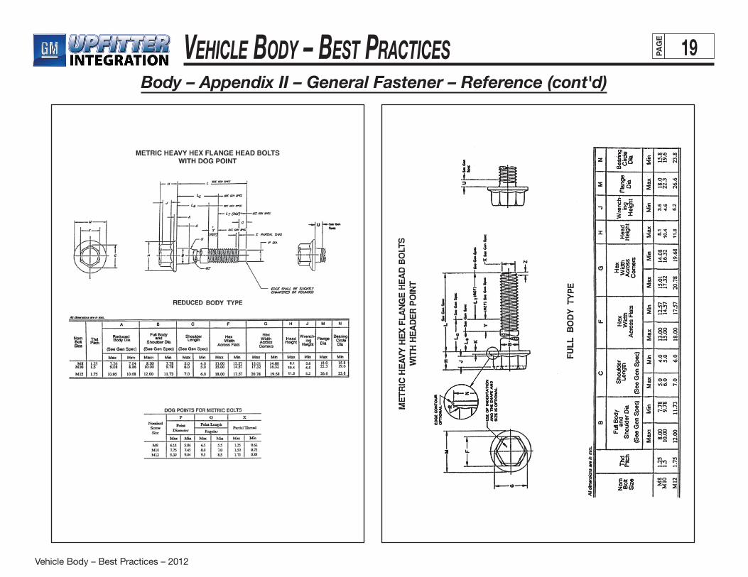
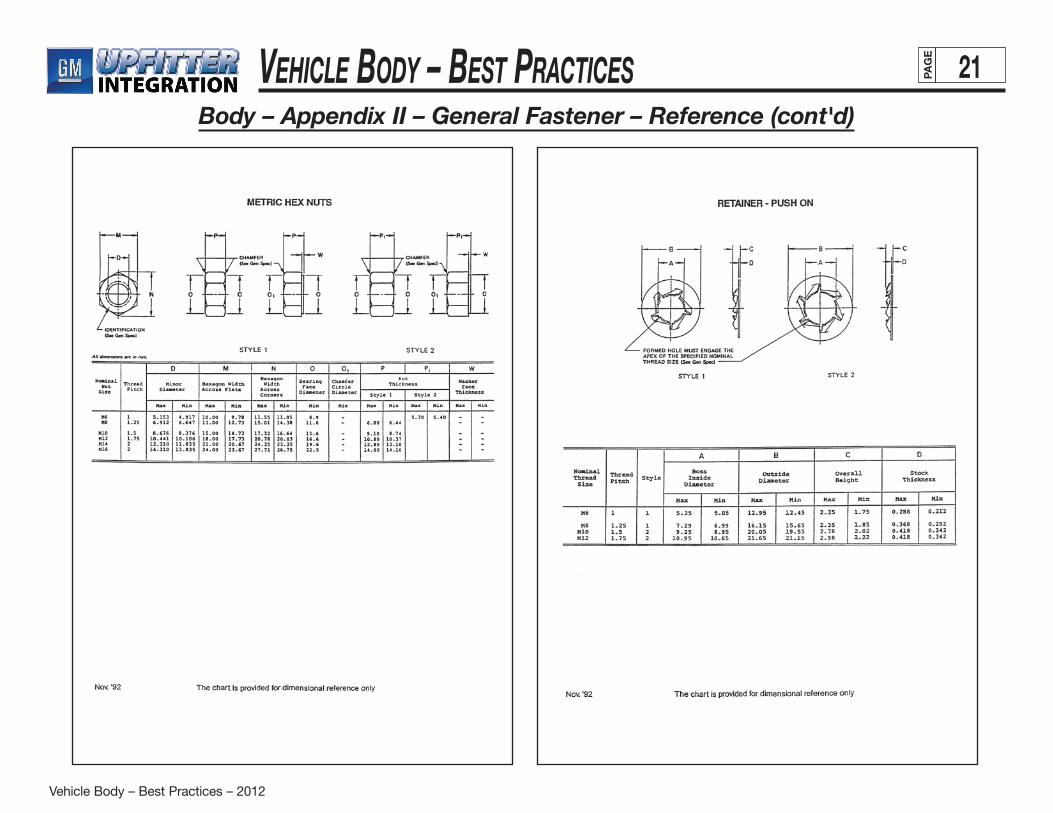
Body – Appendix II – General Fastener – Reference
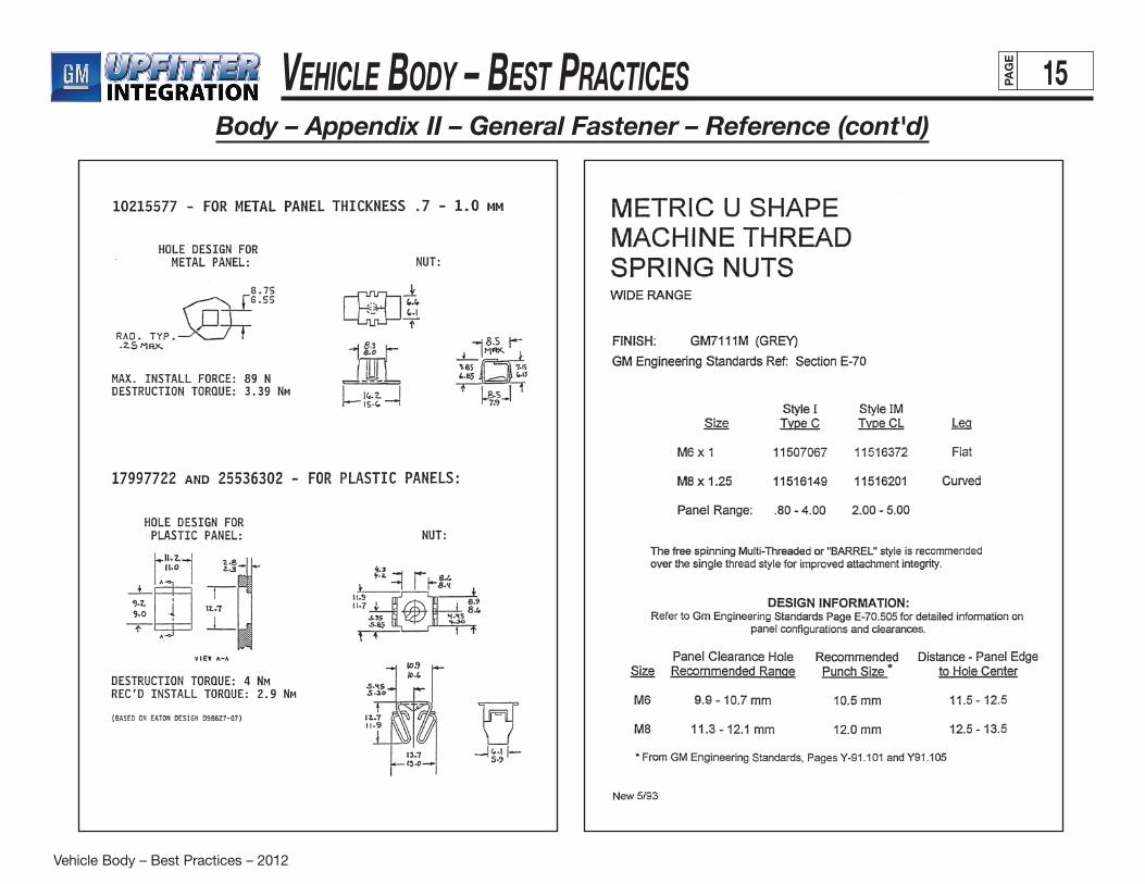
Fastening To Thin Sheet MetalTapping screws have been a standard sheet metal attachment method for years. With the introduction of thinner gauges for cost and weight savings, new concerns became evident. Screws were stripping and loosening because the gauge now only allowed for 1/2 of a thread engagement. Extrusions did not help much because the extrusion wall, due to its thinness, would cut off instead of threading. The practical solution was the release of a new type of tapping screw, one which self extruded and rolled its own thread. This worked well but has shown itself to be somewhat operator sensitive. With the use of plant tooling at its present level of technology, this type of screw has had only moderate success.
Several other thin metal attachment fastening methods have been suggested. “Pop” rivets have always been a cost effective, fairly foolproof method of attaching joints that are in shear. The negative side is that the plants cannot seem to be able to install the parts effectively. Also loose mandrels are a common squeak and rattle complaint. Maintenance of the tool, proper pulling adjustment and periodic replacement of pulling jaws are usual reasons for poor performance of the tools.
The use of U-nuts, another often suggested method of attachment, is not always desirable. Clearance for the legs, installation slots or nearness to a flat edge, ergonomic considerations such as push-on effort, parts count increase, parts falling off or moving aside, are some of the problems encountered when using U-nuts in attachments. While the parts are used today, their shortcomings are carefullyconsidered.
Various snap-ins, plastic as well as steel, do not function well in sheet metal joints, which are mostly in shear. Welding is a possibility, but leaves unsightly appearances. Even when weld attachments are done prior to paint, the weld depression is not acceptable on most visible surfaces. Adhesives are not up to this state of the art yet; although some work is being done at attaching body sheet metal at Ford and Audi/VW.
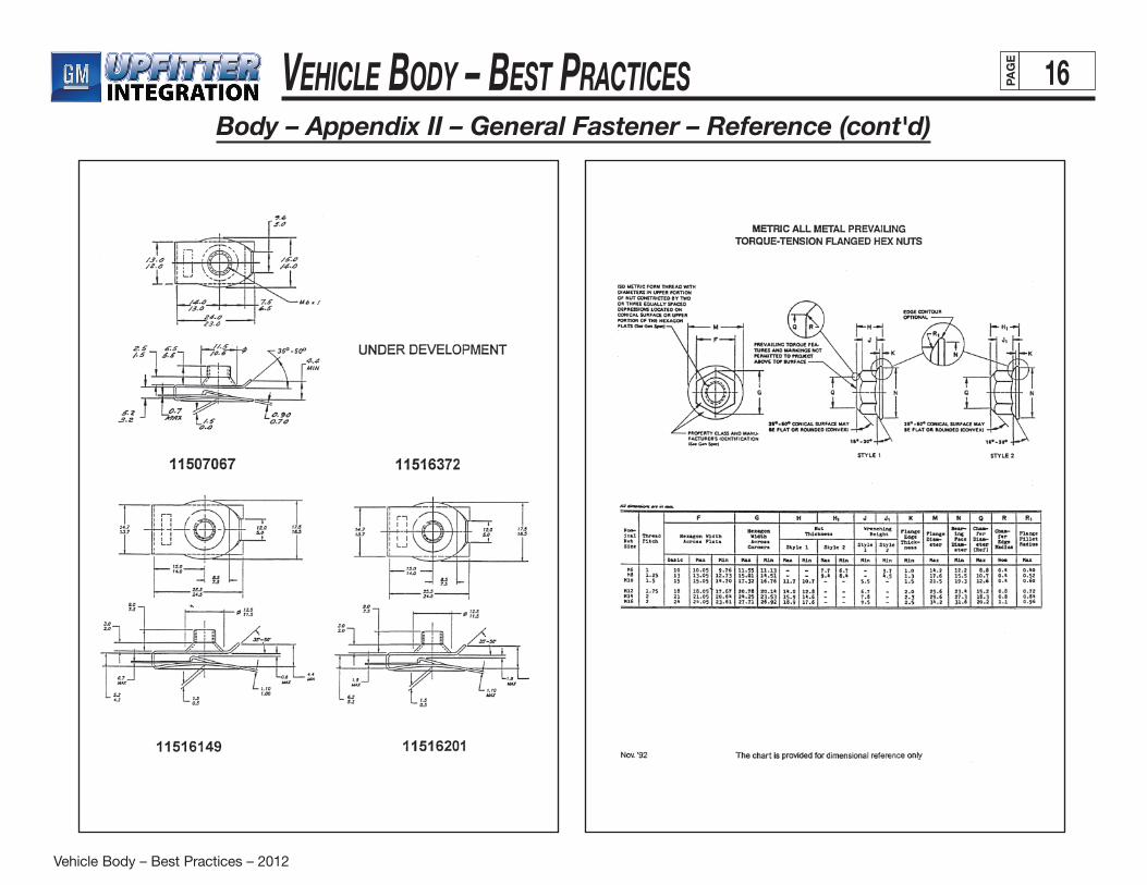
An analysis of the root cause of the problem indicates that the correct solution is to thicken the attachment point. This can be done with the use of welded nuts (negatives are high cost of assembly, energy, labor, handling, poor tolerancing); piercenuts installed in the stamping process (cost effective, but needs space for the physical dimensions of the part and installation tool clearances); the use of tapping plates (cost of energy, tolerances may be a concern); or the use of a snap-in type spring nut. The snap-in type spring nut, when used with a tapping screw, has been shown to be an effective, high-strength joint requiring little physical space, easily installed and relatively inexpensive.
Although tapping screws present some difficulties, their use cannot be totally eliminated. When used with metal-to-metal interfaces such as the snap-in nuts or other joint “thickeners” (i.e., tapping plates), they can effectively be a robustly designed attachment.
Vehicle Body – Best Practices – 2012
Vehicle Body – Best Practices 15PAG
E
Body – Appendix II – General Fastener – Reference (cont'd)
Vehicle Body – Best Practices – 2012
Vehicle Body – Best Practices 16PAG
E
Body – Appendix II – General Fastener – Reference (cont'd)
Vehicle Body – Best Practices – 2012
Vehicle Body – Best Practices 17PAG
E
Body – Appendix II – General Fastener – Reference (cont'd)
Vehicle Body – Best Practices – 2012
Vehicle Body – Best Practices 18PAG
E
Body – Appendix II – General Fastener – Reference (cont'd)
Vehicle Body – Best Practices – 2012
Vehicle Body – Best Practices 19PAG
E
Body – Appendix II – General Fastener – Reference (cont'd)

Vehicle Body – Best Practices – 2012
Vehicle Body – Best Practices 20PAG
E
Body – Appendix II – General Fastener – Reference (cont'd)
Vehicle Body – Best Practices – 2012
Vehicle Body – Best Practices 21PAG
E
Body – Appendix II – General Fastener – Reference (cont'd)
Vehicle Body – Best Practices – 2012
Vehicle Body – Best Practices 22PAG
E
Body – Appendix III – Design Principles To EliminateSqueaks & Rattles – General Principles
Squeak and Rattle-Free Design Checklist:
1. Part does not rattle when shaken – if constrained by functionality, then the part should be hidden or relocated, and isolated using sound-deadening material.
2. Attachment brackets and adjacent parts are designed with the following considerations:
A. Non-cantilevered
B. Positively attached
C. Rigid
D. Self-aligned during assembly
E. Clearance, or interference fit
F. Temperature and environmental effects
G. Surface and surrounding materials
3. For moveable parts (in longitudinal or rotational directions), the component has force preload for all degrees of freedom (including directions resulted from build variation).
4. Wiring, routing, and installation are defined in the Upfitter Integration Electrical manual.
5. Component secured tightly in a static state.
6. Component and surrounding system generate no squeak and rattle from the input of on-road tests.
General Principles:
• Allwiresandtubesmustbesecured(every150to 200 mm depending on stiffness) against a non-squeaky surface – pay particular attention to corner routing.
• Trayanddoorshouldhavefore-aftaswellaslateralpreload when opened or closed.
• Largepanelsneedmorethan2or3attachmentandlocating points.
• Adjacentpartandtrimneedtobeseparatedbydesignedclearance, isolation material, or secured together using tension (not just tension) type fasteners.
• Partsthataredesignedtorotateormoveshouldbepre-loaded to prevent rattle.
• Avoidcontactofpartsmadewithsimilarsurfacematerials.
• Considertheeffectoftemperatureandloadcyclingfatigue on part's tension.
• Fastenerslocationsmustbeeasilyaccessibleduringinstallation, and guides or locating pins provided to ensure the fasteners or parts are correctly and fully seated.
(continued on next page)

Vehicle Body – Best Practices – 2012
Vehicle Body – Best Practices 23PAG
E
Body – Appendix III – Design Principles To EliminateSqueaks & Rattles – General Principles (cont'd)
(continued on next page)
Important General Principles
All wires and tubes must be secured (every 150 to 200 mm depending on stiffness) against a non-squeaky surface – pay particular attention to corner routing.
Tray and door should have fore-aft as well as lateral preload when opened or closed.
Large panels need more than 2 or 3 attachment and locating points.
Adjacent part and trim need to be separated by designed clearance,
isolation material, or secured together using tension (not just
tension) type fasteners
Vehicle Body – Best Practices – 2012
Vehicle Body – Best Practices 24PAG
E
Body – Appendix III – Design Principles To EliminateSqueaks & Rattles – General Principles (cont'd)
(continued on next page)
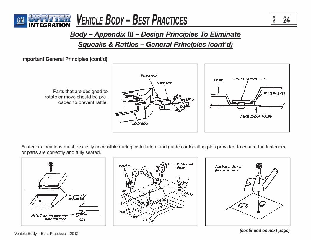
Important General Principles (cont'd)
Parts that are designed to rotate or move should be pre-
loaded to prevent rattle.
Fasteners locations must be easily accessible during installation, and guides or locating pins provided to ensure the fasteners or parts are correctly and fully seated.
Vehicle Body – Best Practices – 2012
Vehicle Body – Best Practices 25PAG
E
Body – Appendix III – Design Principles To EliminateSqueaks & Rattles – General Principles (cont'd)
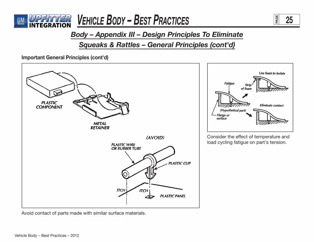
Important General Principles (cont'd)
Avoid contact of parts made with similar surface materials.
Consider the effect of temperature and load cycling fatigue on part's tension.

Vehicle Body – Best Practices – 2012
Vehicle Body – Best Practices 26PAG
E
Body – Appendix III – Design Principles To EliminateSqueaks & Rattles – Instrument Panel & Dash
Instrument Panel & Dash Checklist:
• Securewiresandcablesinchannelorconduit.
• Placecableclipalongthefulllengthofthecableat150mm to 200 mm intervals.
• Foamwrapconnectorstopreventcontact,or apply foam to area of contact.
• Insulatingwireisinsufficientunlessitisalsosecured.
• Securewireandcabletonon-vibratingsurfaces.
• Securemoduleswithrobustattachment(ex:rosebud).
• Provide"dummy"connectorattachmentsforunusedconnectors.
• Whenitisuneconomicaltousedummyconnector,secure loose module up to the end of the connector (already wrapped with insulation) by taping onto a non-vibrating surface.
• Whenusingrubber,foaminsulator,orsnap-inplastictabs, consider the anticipated thermal environment and degradation with time.
• Utilizestand-offribstocreatepre-loadorclearancebetween surfaces.
• Fastenersmustbestrongerthanthethreadtopreventstripping.
• Eliminatefastenerswhenasinglerigidpieceorweldedconstruction is feasible.
• DesignclearancebetweenwindshieldandIPpadleading edge should be at least 7mm with build variation considered.
• ClearanceofIPpadtopillarmoldingshouldbe10mm.
• ForwardedgeoftheIPmusthave2mmdesigngapvertically – use standoff on the cowl as locators and for screw attachments.
• ClearanceofIPpadtodoortrimorpillarmoldingshouldbe at least 15mm.
• ClearanceofIPpadtopillargarnishmoldingshouldbeat least 3mm
• Trimplatesshouldhavetighttolerancetoensure clearance or interface fit.
• Swing-down(or-out)ashtraysmustbedesigned with strong spring or detent to hold them in open or closed position.
• Secureheavyloads(suchasradioandHVACcontroller)with pin locators, shelves or other non-cantilevered supports so that screws would only have to be used to secure them in place (vs. having the fasteners providing all the lifting force).
• Odometersetshafts,clocksetshafts(andthelike)musthave sufficient clearance or be insulated (using rubber grommets) from the cluster face.
(continued on next page)

Vehicle Body – Best Practices – 2012
Vehicle Body – Best Practices 27PAG
E
Body – Appendix III – Design Principles To EliminateSqueaks & Rattles – Instrument Panel & Dash (cont'd)
Instrument Panel & Dash Checklist (cont'd):
• Provideinsulatingmaterial(foamoranti-itchtape)between surfaces in proximity to prevent rattling or vibration.
• Steeringcolumnpanelsmusthavelargeclearancesto account for potential variations in steering column location.
• Avoidplasticbossesintheinjectionmoldedpanelandtrim plate in structural application since the plastic will creep under load.
• Whentwovinylorplasticpanelsarerequiredtobeattached, a concealed joint line should be designed.
• Snap-inassemblyshouldbereservedforcomponents that are not frequently removed.
• Usespringorrubbertopreloadlatchtopreventrattle.
• Utilizefoamasaninsulatororaspacerinhollowspacesto prevent oil-canning sound.
• Foamwrapwiresthatareintendedtobelongorunsecured for servicing and installation (i.e., HVAC and radio wires).
• Wireandcableemergingfromaholeorconduitshouldbe secured with tape or rubber grommet to prevent rattle inside conduit.
• Conduitmustbeappropriatelysizedsothatcabledoesnot rattle inside.
• Increasetrim'staperedcorner(ordecreaseriblength)toprevent squak or itch..
• Trimshouldnotfunctionasdirectloadingsupport.
• Attachmentfastenershouldbeinatensionstatewiththeattaching surface.
• IPsubframe(ifpresent)shouldbestiffandattachedtothe main frame to reduce trim bending and twisting.
• Insteadofusingsnapfittojointtwoplasticparts,consider machine screw fastener with U-nut or snap-in for better retention.
• AreaaroundtheIPinstallationrollpinandbracketmustbe secured and rigid to prevent itching of the pin against the bracket.
• Trimsthataredesignedtopreloadagainsteachothermay lose their tension because of temperature cycling.
Vehicle Body – Best Practices – 2012
Vehicle Body – Best Practices 28PAG
E
Body – Appendix III – Design Principles To EliminateSqueaks & Rattles – Instrument Panel & Dash (cont'd)
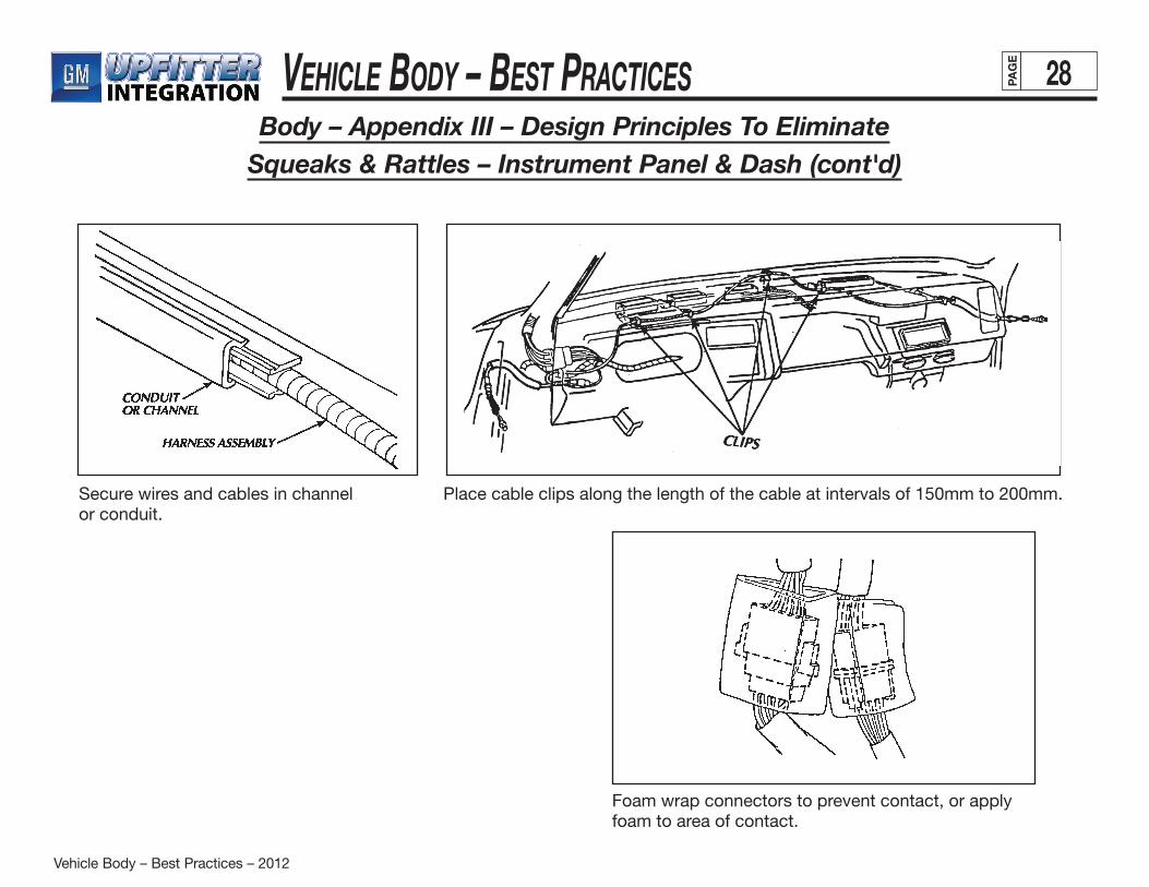
Secure wires and cables in channelor conduit.
Place cable clips along the length of the cable at intervals of 150mm to 200mm.
Foam wrap connectors to prevent contact, or apply foam to area of contact.
Vehicle Body – Best Practices – 2012
Vehicle Body – Best Practices 29PAG
E
Body – Appendix III – Design Principles To EliminateSqueaks & Rattles – Instrument Panel & Dash (cont'd)
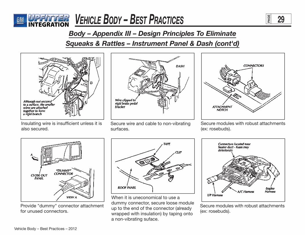
Insulating wire is insufficient unless it is also secured.
Secure wire and cable to non-vibrating surfaces.
Secure modules with robust attachments (ex: rosebuds).
When it is uneconomical to use a dummy connector, secure loose module up to the end of the connector (already wrapped with insulation) by taping onto a non-vibrating suface.
Secure modules with robust attachments (ex: rosebuds).
Provide "dummy" connector attachment for unused connectors.

Vehicle Body – Best Practices – 2012
Vehicle Body – Best Practices 30PAG
E
Body – Appendix III – Design Principles To EliminateSqueaks & Rattles – Instrument Panel & Dash (cont'd)
• DesignclearancebetweenwindshieldandIPpadleading edge should be at least 7mm with build variation considered.
• ClearanceofIPPadtopillarmoldingshould be 10mm.
• ForwardedgeoftheIPmusthave2mmdesigngapvertically – use standoff on the cowl as locators and for screw attachments.
• ClearanceofIPpadtodoortrimorpillarmoldingshould be at least 15mm.
• ClearanceofIPPadtopillargarnishmolding should be at least 3mm.

Vehicle Body – Best Practices – 2012
Vehicle Body – Best Practices 31PAG
E
Body – Appendix III – Design Principles To EliminateSqueaks & Rattles – Instrument Panel & Dash (cont'd)
Trim plates should have tight tolerance to ensure clearance or interface fit.
Swing-down (or -out) ash trays must be designed with strong spring or a detent to hold them in open or closed position.
Secure heavy loads (such as radio and HVAC controller) with pin locators, shelves or other non-cantilevered supports so that screws would only have to be used to secure them in place (vs. having the fasteners providing all the lifting force).
Odometer set shafts, clock set shafts (and the like) must have sufficient clearance or be insulated (using rubber grommets) from the cluster face.

Vehicle Body – Best Practices – 2012
Vehicle Body – Best Practices 32PAG
E
Body – Appendix III – Design Principles To EliminateSqueaks & Rattles – Instrument Panel & Dash (cont'd)
Provide insulating material (foam or anti-itch tape) between surfaces in proximity from rattling or vibration.
Steering column panels must have large clearance to account for potential variation in steering column location.
Avoid plastic bosses in the injection molded panel and trim plate in structural application since the plastic will creep under load.
Snap-in assembly should be reserved for components that are not frequently removed.
Use spring or rubber to preload latch to prevent rattle.
When two vinyl or plastic panels are required to be attached together – a concealed joint line should be designed.
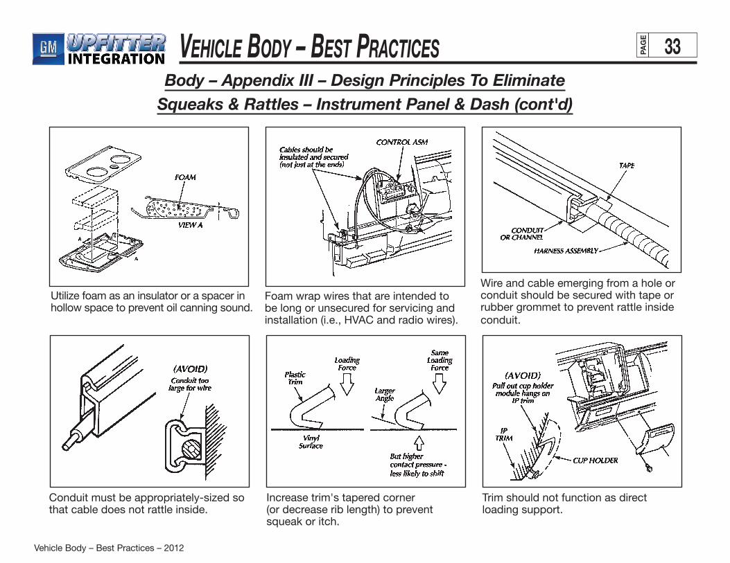
Vehicle Body – Best Practices – 2012
Vehicle Body – Best Practices 33PAG
E
Body – Appendix III – Design Principles To EliminateSqueaks & Rattles – Instrument Panel & Dash (cont'd)
Utilize foam as an insulator or a spacer in hollow space to prevent oil canning sound.
Foam wrap wires that are intended to be long or unsecured for servicing and installation (i.e., HVAC and radio wires).
Wire and cable emerging from a hole or conduit should be secured with tape or rubber grommet to prevent rattle inside conduit.
Increase trim's tapered corner (or decrease rib length) to prevent squeak or itch.
Trim should not function as direct loading support.
Conduit must be appropriately-sized so that cable does not rattle inside.
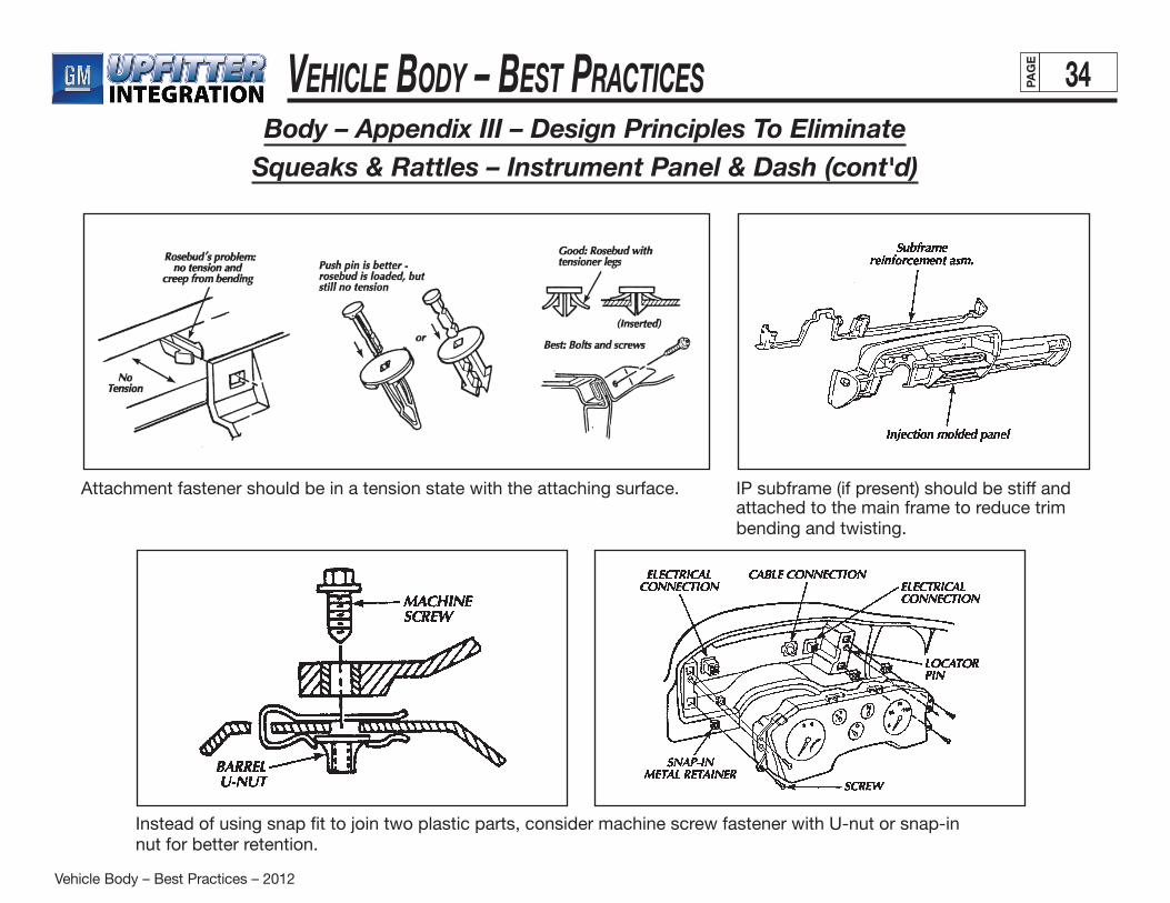
Vehicle Body – Best Practices – 2012
Vehicle Body – Best Practices 34PAG
E
Body – Appendix III – Design Principles To EliminateSqueaks & Rattles – Instrument Panel & Dash (cont'd)
IP subframe (if present) should be stiff and attached to the main frame to reduce trim bending and twisting.
Attachment fastener should be in a tension state with the attaching surface.
Instead of using snap fit to join two plastic parts, consider machine screw fastener with U-nut or snap-in nut for better retention.
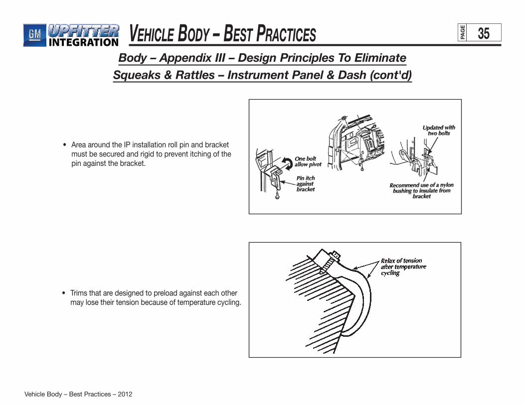
Vehicle Body – Best Practices – 2012
Vehicle Body – Best Practices 35PAG
E
Body – Appendix III – Design Principles To EliminateSqueaks & Rattles – Instrument Panel & Dash (cont'd)
• AreaaroundtheIPinstallationrollpinandbracketmust be secured and rigid to prevent itching of the pin against the bracket.
• Trimsthataredesignedtopreloadagainsteachothermay lose their tension because of temperature cycling.
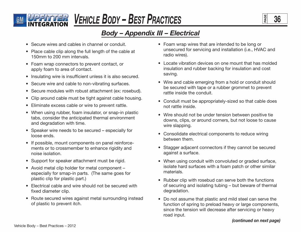
Vehicle Body – Best Practices – 2012
Vehicle Body – Best Practices 36PAG
E
Body – Appendix III – Electrical
• Securewiresandcablesinchannelorconduit.
• Placecableclipalongthefulllengthofthecableat150mm to 200 mm intervals.
• Foamwrapconnectorstopreventcontact,or apply foam to area of contact.
• Insulatingwireisinsufficientunlessitisalsosecured.
• Securewireandcabletonon-vibratingsurfaces.
• Securemoduleswithrobustattachment(ex:rosebud).
• Cliparoundcablemustbetightagainstcablehousing.
• Eliminateexcesscableorwiretopreventrattle.
• Whenusingrubber,foaminsulator,orsnap-inplastictabs, consider the anticipated thermal environment and degradation with time.
• Speakerwireneedstobesecured–especiallyfor loose ends.
• Ifpossible,mountcomponentsonpanelreinforce- ments or to crossmember to enhance rigidity and noise isolation.
• Supportforspeakerattachmentmustberigid.
• Avoidmetalclipholderformetalcomponent– especially for smap-in parts. (The same goes for plastic clip for plastic part.)
• Electricalcableandwireshouldnotbesecuredwithfixed diameter clip.
• Routesecuredwiresagainstmetalsurroundinginsteadof plastic to prevent itch.
• Foamwrapwiresthatareintendedtobelongorunsecured for servicing and installation (i.e., HVAC and radio wires).
• Locatevibrationdevicesononemountthathasmoldedinsulation and rubber backing for insulation and cost saving.
• Wireandcableemergingfromaholdorconduitshouldbe secured with tape or a rubber grommet to prevent rattle inside the conduit.
• Conduitmustbeappropriately-sizedsothatcabledoesnot rattle inside.
• Wireshouldnotbeundertensionbetweenpositivetiedowns, clips, or around corners, but not loose to cause wire slapping.
• Consolidateelectricalcomponentstoreducewiringbetween them.
• Staggeradjacentconnectorsiftheycannotbesecuredagainst a surface.
• Whenusingconduitwithconvolutedorgradedsurface,isolate hard surfaces with a foam patch or other similar materials.
• Rubberclipwithrosebudcanserveboththefunctionsof securing and isolating tubing – but beware of thermal degradation.
• Donotassumethatplasticandmildsteelcanservethefunction of spring to preload heavy or large components, since the tension will decrease after servicing or heavy road input.
(continued on next page)
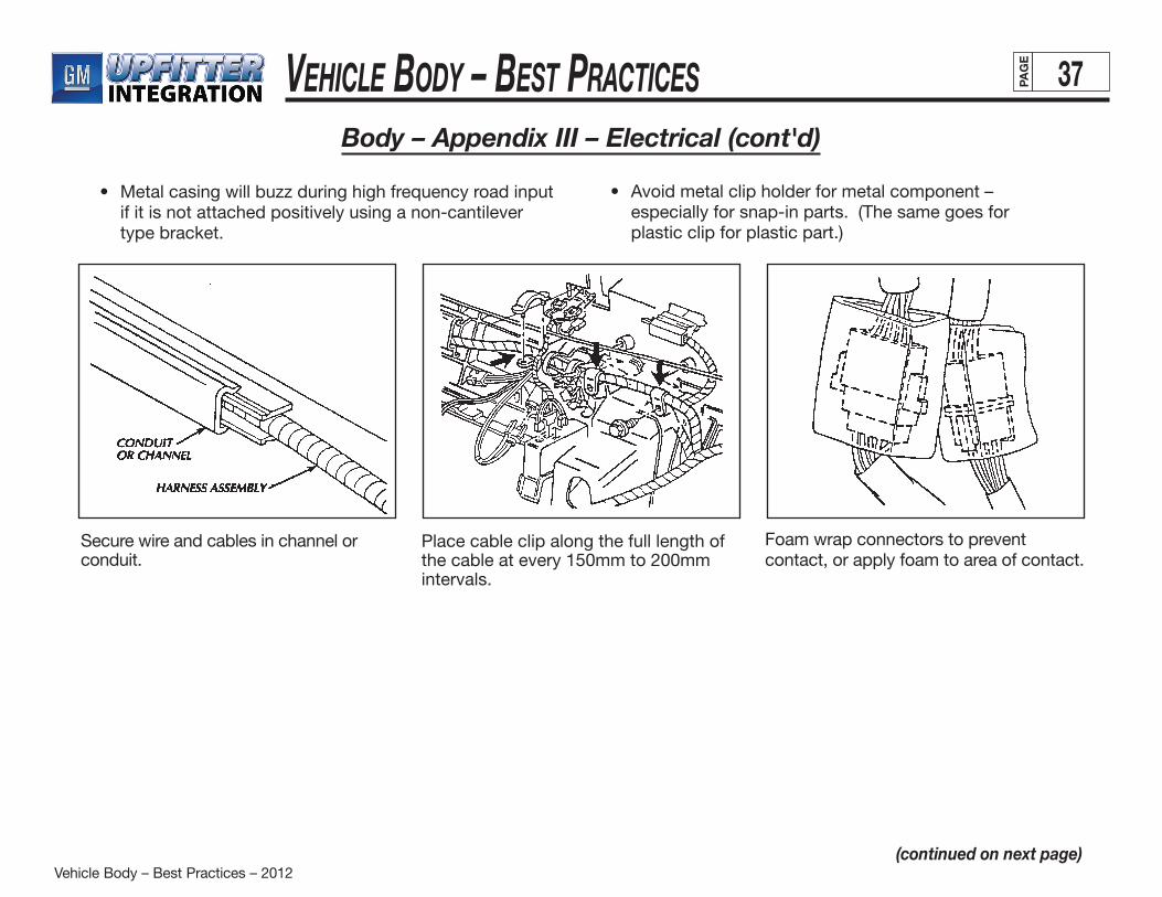
Vehicle Body – Best Practices – 2012
Vehicle Body – Best Practices 37PAG
E
Body – Appendix III – Electrical (cont'd)
• Metalcasingwillbuzzduringhighfrequencyroadinput if it is not attached positively using a non-cantilever type bracket.
(continued on next page)
• Avoidmetalclipholderformetalcomponent– especially for snap-in parts. (The same goes for plastic clip for plastic part.)
Secure wire and cables in channel or conduit.
Place cable clip along the full length of the cable at every 150mm to 200mm intervals.
Foam wrap connectors to prevent contact, or apply foam to area of contact.
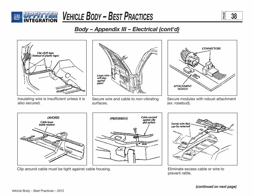
Vehicle Body – Best Practices – 2012
Vehicle Body – Best Practices 38PAG
E
Body – Appendix III – Electrical (cont'd)
(continued on next page)
Insulating wire is insufficient unless it is also secured.
Secure wire and cable to non-vibrating surfaces.
Secure modules with robust attachment (ex: rosebud).
Eliminate excess cable or wire to prevent rattle.
Clip around cable must be tight against cable housing.
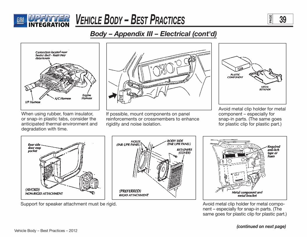
Vehicle Body – Best Practices – 2012
Vehicle Body – Best Practices 39PAG
E
Body – Appendix III – Electrical (cont'd)
(continued on next page)
When using rubber, foam insulator, or snap-in plastic tabs, consider the anticipated thermal environment and degradation with time.
If possible, mount components on panel reinforcements or crossmembers to enhance rigidity and noise isolation.
Avoid metal clip holder for metal component – especially for snap-in parts. (The same goes for plastic clip for plastic part.)
Support for speaker attachment must be rigid. Avoid metal clip holder for metal compo-nent – especially for snap-in parts. (The same goes for plastic clip for plastic part.)
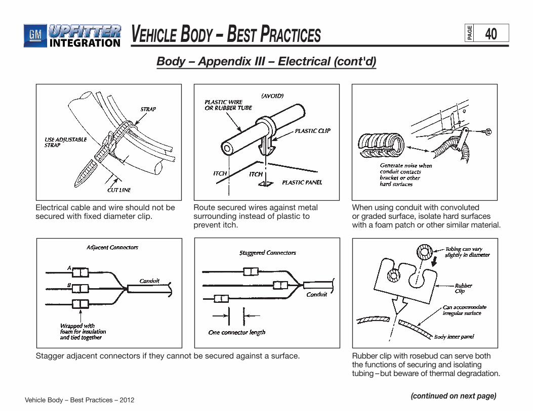
Vehicle Body – Best Practices – 2012
Vehicle Body – Best Practices 40PAG
E
Body – Appendix III – Electrical (cont'd)
(continued on next page)
Electrical cable and wire should not be secured with fixed diameter clip.
Route secured wires against metal surrounding instead of plastic to prevent itch.
When using conduit with convoluted or graded surface, isolate hard surfaces with a foam patch or other similar material.
Stagger adjacent connectors if they cannot be secured against a surface. Rubber clip with rosebud can serve both the functions of securing and isolating tubing – but beware of thermal degradation.
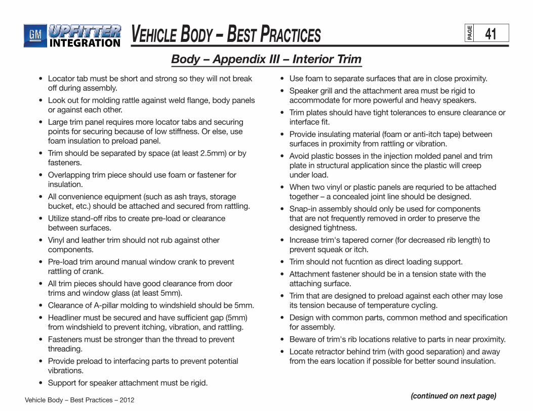
Vehicle Body – Best Practices – 2012
Vehicle Body – Best Practices 41PAG
E
Body – Appendix III – Interior Trim
(continued on next page)
• Locatortabmustbeshortandstrongsotheywillnotbreakoff during assembly.
• Lookoutformoldingrattleagainstweldflange,bodypanels or against each other.
• Largetrimpanelrequiresmorelocatortabsandsecuring points for securing because of low stiffness. Or else, use foam insulation to preload panel.
• Trimshouldbeseparatedbyspace(atleast2.5mm)orby fasteners.
• Overlappingtrimpieceshouldusefoamorfastenerfor insulation.
• Allconvenienceequipment(suchasashtrays,storagebucket, etc.) should be attached and secured from rattling.
• Utilizestand-offribstocreatepre-loadorclearance between surfaces.
• Vinylandleathertrimshouldnotrubagainstother components.
• Pre-loadtrimaroundmanualwindowcranktoprevent rattling of crank.
• Alltrimpiecesshouldhavegoodclearancefromdoor trims and window glass (at least 5mm).
• ClearanceofA-pillarmoldingtowindshieldshouldbe5mm.
• Headlinermustbesecuredandhavesufficientgap(5mm) from windshield to prevent itching, vibration, and rattling.
• Fastenersmustbestrongerthanthethreadtoprevent threading.
• Providepreloadtointerfacingpartstopreventpotentialvibrations.
• Supportforspeakerattachmentmustberigid.
• Usefoamtoseparatesurfacesthatareincloseproximity.
• Speakergrillandtheattachmentareamustberigidto accommodate for more powerful and heavy speakers.
• Trimplatesshouldhavetighttolerancestoensureclearanceor interface fit.
• Provideinsulatingmaterial(foamoranti-itchtape)between surfaces in proximity from rattling or vibration.
• Avoidplasticbossesintheinjectionmoldedpanelandtrim plate in structural application since the plastic will creep under load.
• Whentwovinylorplasticpanelsarerequriedtobeattached together – a concealed joint line should be designed.
• Snap-inassemblyshouldonlybeusedforcomponents that are not frequently removed in order to preserve the designed tightness.
• Increasetrim'staperedcorner(fordecreasedriblength)to prevent squeak or itch.
• Trimshouldnotfucntionasdirectloadingsupport.
• Attachmentfastenershouldbeinatensionstatewiththe attaching surface.
• Trimthataredesignedtopreloadagainsteachothermaylose its tension because of temperature cycling.
• Designwithcommonparts,commonmethodandspecification for assembly.
• Bewareoftrim'sriblocationsrelativetopartsinnearproximity.
• Locateretractorbehindtrim(withgoodseparation)andaway from the ears location if possible for better sound insulation.

Vehicle Body – Best Practices – 2012
Vehicle Body – Best Practices 42PAG
E
Body – Appendix III – Interior Trim (cont'd)
(continued on next page)
All convenience equipment (such as ash trays, storage bucket, etc.) should be attached and secured from rattling.
Utilize stand-off ribs to create pre-load or clearance between surfaces.
Vinyl and leather trim should not rub against other components.
Pre-load trim around manual window crank to prevent rattling of crank.
Headliner must be secured and have sufficient gap (5mm) from windshield to prevent itching, vibration, and rattling.
All trim pieces should have good clearance from door trims and window glass (at least 5mm).

Vehicle Body – Best Practices – 2012
Vehicle Body – Best Practices 43PAG
E
Body – Appendix III – Interior Trim (cont'd)
(continued on next page)
Locators and fasteners must be designed to reduce build and user variations for secure fit and retention.
Use foam to separate surfaces that are in close proximity.
Speaker grill and the attachment area must be rigid to accommodate for more powerful and heavy speakers.
Provide insulating material (foam or anti-itch tape) between surfaces in proximity from rattling or vibration.
Trim plates should have tight tolerances to ensure clearance or interface fit.
Avoid plastic bosses in the injection molded panel and trim plate in structural application since the plastic will creep under load.

Vehicle Body – Best Practices – 2012
Vehicle Body – Best Practices 44PAG
E
Body – Appendix III – Body & Exterior Trim
(continued on next page)
• Reduceoravoidmetalmaintenanceaccesspanelbecauseof the possible loss, loose or missing screws during assembly.
• Componentshouldnotbemountedinthecenteroflargepanels that have low structural stiffness.
• Componentshouldbemountedtoflanges,atcorners,ribs or beads – but need to consider fatigue from stress concentration and component contact.
• Utilizefoamasaninsulatororaspacerinhollowspacetoprevent oil canning sound.
• Insteadofsnapfittojointwoplasticparts,considermachinescrew fastener with U-nut or snap-in for better retention.
• Mostofrattlingcanbeeliminatedifthevehiclebodyorthemounting bracket is stiff against bending and twisting.
• Avoidmultipleandoverlappingtrimpiecesduetoitchanddifficult alignment.
• Windowmoldingsandexternaltrimsmustbemadeofmaterials that will not itch when rubbed against body surfaces (check by rubbing sample against painted panel).
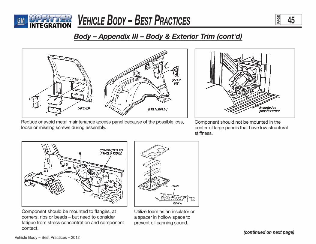
Vehicle Body – Best Practices – 2012
Vehicle Body – Best Practices 45PAG
E
Body – Appendix III – Body & Exterior Trim (cont'd)
(continued on next page)
Reduce or avoid metal maintenance access panel because of the possible loss, loose or missing screws during assembly.
Component should not be mounted in the center of large panels that have low structural stiffness.
Utilize foam as an insulator or a spacer in hollow space to prevent oil canning sound.
Component should be mounted to flanges, at corners, ribs or beads – but need to consider fatigue from stress concentration and component contact.
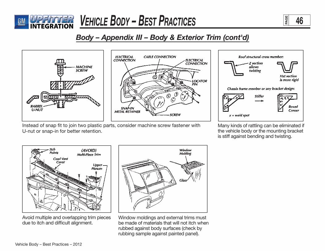
Vehicle Body – Best Practices – 2012
Vehicle Body – Best Practices 46PAG
E
Many kinds of rattling can be eliminated if the vehicle body or the mounting bracket is stiff against bending and twisting.
Window moldings and external trims must be made of materials that will not itch when rubbed against body surfaces (check by rubbing sample against painted panel).
Avoid multiple and overlapping trim pieces due to itch and difficult alignment.
Body – Appendix III – Body & Exterior Trim (cont'd)
Instead of snap fit to join two plastic parts, consider machine screw fastener with U-nut or snap-in for better retention.

Vehicle Body – Best Practices – 2012
Vehicle Body – Best Practices 47PAG
E
Body – Appendix III – Seat and Seat Belt
• Providepreloadtointerfacingpartstopreventpotentialvibrations.
• Seatbelttrimpiecemustbesecuredandnotrubagainstother trim piece or with weather strips.
• Seatmechanismshouldhavegoodclearancewiththeseatbottom suspension wires when the seat is occupied.
• Userubberstop,spring,orseatmaterialtoloaddownlatch both in the seat-up and seat-down position.
• Vinylandleathershouldnotrubagainstothercomponents or trim.
• Usesoftermaterialforretractorandbucklehousing.
• Thereshouldbeminimalmovementoflatchplaneinsidethebuckle.
• Forcomponentthathasoneattachmentpoint,anti-rotationprovision must be designed in.
• Whenseatbeltsarenotinuse,thelatchshouldonlybeclose to sound-deadening type material (ex: carpet) and not rest near hard trim surfaces.
• Forremoveableseatingarrangement,theremustbeprovision for storing the latch plane (of overhead retractor, etc.)

Vehicle Body – Best Practices – 2012
Vehicle Body – Best Practices 48PAG
E
Body – Appendix III – Seat and Seat Belt (cont'd)
(continued on next page)
Provide preload to interfacing parts to prevent potential vibrations.
Seat belt trim piece must be secured and not rub against other trim piece or with weather strips.
Seat mechanism should have good clearance with the seat bottom suspension wires when the seat is occupied.
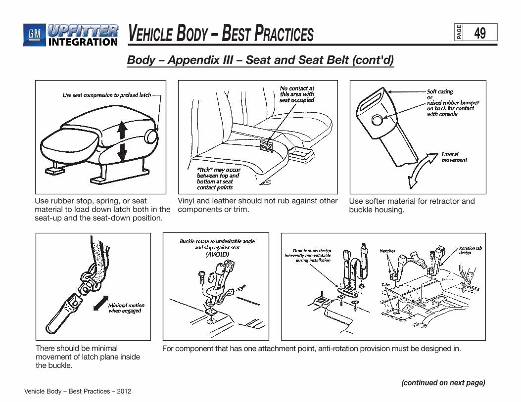
Vehicle Body – Best Practices – 2012
Vehicle Body – Best Practices 49PAG
E
Use rubber stop, spring, or seat material to load down latch both in the seat-up and the seat-down position.
Vinyl and leather should not rub against other components or trim.
Use softer material for retractor and buckle housing.
For component that has one attachment point, anti-rotation provision must be designed in.There should be minimal movement of latch plane inside the buckle.
Body – Appendix III – Seat and Seat Belt (cont'd)
(continued on next page)
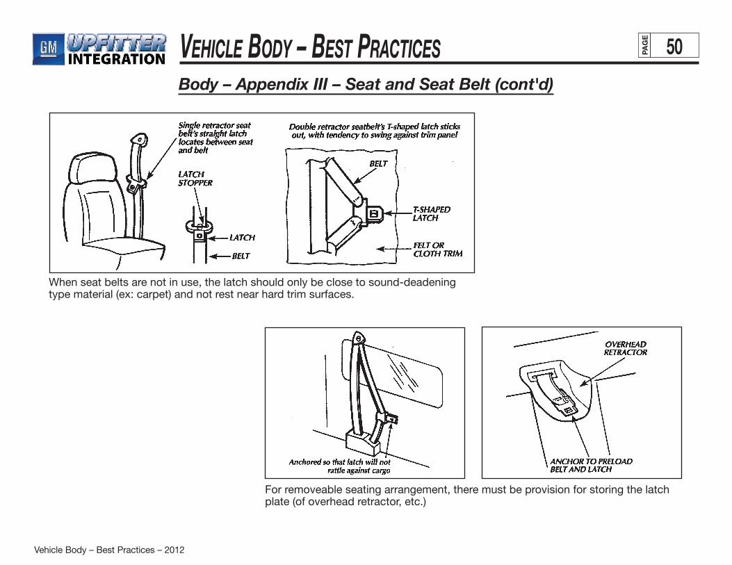
Vehicle Body – Best Practices – 2012
Vehicle Body – Best Practices 50PAG
E
When seat belts are not in use, the latch should only be close to sound-deadening type material (ex: carpet) and not rest near hard trim surfaces.
Body – Appendix III – Seat and Seat Belt (cont'd)
For removeable seating arrangement, there must be provision for storing the latch plate (of overhead retractor, etc.)
Chassis – Best Practices – 2012
Chassis – Best PraCtiCes iPAG
E
EXTENDING WHEELBASE/MOVING AXLE ������������������������������������������������������������������������������������������������������������������������������������������������� 1 Frame Extension ������������������������������������������������������������������������������������������������������������������������������������������������������������������������������������� 1 Alterations ��������������������������������������������������������������������������������������������������������������������������������������������������������������������������������������� 1 Frame ���������������������������������������������������������������������������������������������������������������������������������������������������������������������������������������������� 1 Altering the Wheelbase ��������������������������������������������������������������������������������������������������������������������������������������������������������������������������� 2 Frame Splice Location�������������������������������������������������������������������������������������������������������������������������������������������������������������������� 2 Frame Splice Preparation ��������������������������������������������������������������������������������������������������������������������������������������������������������������� 3 Frame Splice Procedure ����������������������������������������������������������������������������������������������������������������������������������������������������������������� 4 Extending the Frame (Rear Overhang) ��������������������������������������������������������������������������������������������������������������������������������������������������� 7 Holes ������������������������������������������������������������������������������������������������������������������������������������������������������������������������������������������������������� 8 Crossmembers ���������������������������������������������������������������������������������������������������������������������������������������������������������������������������������������� 9 Analyzing Frame Failure Causes ���������������������������������������������������������������������������������������������������������������������������������������������������������� 10 Collisions �������������������������������������������������������������������������������������������������������������������������������������������������������������������������������������� 10 Excessive Bending Moment ��������������������������������������������������������������������������������������������������������������������������������������������������������� 10 Localized Stress Concentration ��������������������������������������������������������������������������������������������������������������������������������������������������� 10 Attaching Reinforcements ������������������������������������������������������������������������������������������������������������������������������������������������������������ 12 Terminating Reinforcements ��������������������������������������������������������������������������������������������������������������������������������������������������������� 13 Frame Repair and Reinforcement: General Rules ����������������������������������������������������������������������������������������������������������������������������������������������������������������������� 13 Welding ������������������������������������������������������������������������������������������������������������������������������������������������������������������������������������������������� 13 Welding Equipment ���������������������������������������������������������������������������������������������������������������������������������������������������������������������� 14 Welding Methods �������������������������������������������������������������������������������������������������������������������������������������������������������������������������� 15 Dissimilar Metals��������������������������������������������������������������������������������������������������������������������������������������������������������������������������� 15 Driveshaft (Propshaft) Extension ���������������������������������������������������������������������������������������������������������������������������������������������������������� 16 Driveshaft Extension Design �������������������������������������������������������������������������������������������������������������������������������������������������������� 16 Two-Piece Driveshaft Bearings ���������������������������������������������������������������������������������������������������������������������������������������������������� 17 Universal Joint Angles and Phasing ��������������������������������������������������������������������������������������������������������������������������������������������� 18 Multiple-Piece Driveshaft Alignment Procedure �������������������������������������������������������������������������������������������������������������������������� 19
Index
(continued on next page)
Chassis – Best Practices – 2012
Chassis – Best PraCtiCes iiPAG
E
BODY MOUNTING ��������������������������������������������������������������������������������������������������������������������������������������������������������������������������������������� 20 General Requirements �������������������������������������������������������������������������������������������������������������������������������������������������������������������������� 20 Body Mounting Considerations ������������������������������������������������������������������������������������������������������������������������������������������������������������ 21 Body/Equipment Attachment Methods ������������������������������������������������������������������������������������������������������������������������������������������������ 21 Body Mounting Fasteners ������������������������������������������������������������������������������������������������������������������������������������������������������������ 22 Prevailing Torque Nuts (PTN)�������������������������������������������������������������������������������������������������������������������������������������������������������� 23 NTEA Recommended Body-Mounting Practices �������������������������������������������������������������������������������������������������������������������������������� 23 Type 1 – U-Bolt/Threaded Rod and End Plate ���������������������������������������������������������������������������������������������������������������������������� 23 Type 2 – Brackets and Pinch Bolts ���������������������������������������������������������������������������������������������������������������������������������������������� 23 Type 3 – Rigid Mounting (Service/Utility) ������������������������������������������������������������������������������������������������������������������������������������� 23 Type 4 – Shear Plate Mounted ����������������������������������������������������������������������������������������������������������������������������������������������������� 23 NTEA Body Classifications ����������������������������������������������������������������������������������������������������������������������������������������������������������� 24 Shear Plate Attachments ���������������������������������������������������������������������������������������������������������������������������������������������������������������������� 28
FUEL SYSTEMS ������������������������������������������������������������������������������������������������������������������������������������������������������������������������������������������� 29 Fuel Fill �������������������������������������������������������������������������������������������������������������������������������������������������������������������������������������������������� 29 Fuel Lines ���������������������������������������������������������������������������������������������������������������������������������������������������������������������������������������������� 30 Fuel Tanks ��������������������������������������������������������������������������������������������������������������������������������������������������������������������������������������������� 31 Auxiliary Fuel Tanks ���������������������������������������������������������������������������������������������������������������������������������������������������������������������� 32 Diesel Exhaust Fluid (DEF) System ������������������������������������������������������������������������������������������������������������������������������������������������������ 32
BRAKES�������������������������������������������������������������������������������������������������������������������������������������������������������������������������������������������������������� 33 General Requirements ���������������������������������������������������������������������������������������������������������������������������������������������������������������������������������� 33 Federal Standards and Regulations ������������������������������������������������������������������������������������������������������������������������������������������������������������� 33 Modification Checklist �������������������������������������������������������������������������������������������������������������������������������������������������������������������������� 33 Brake Lines��������������������������������������������������������������������������������������������������������������������������������������������������������������������������������������������34Parking Brake Systems ��������������������������������������������������������������������������������������������������������������������������������������������������������������������������������� 35 Electronic Dynamic Rear Proportioning (DRP) ��������������������������������������������������������������������������������������������������������������������������������������������� 36
Index (cont'd)
Chassis – Best Practices – 2012
Chassis – Best PraCtiCes iiiPAG
E
Index (cont'd)EXHAUST SYSTEM ������������������������������������������������������������������������������������������������������������������������������������������������������������������������������������� 37 Exhaust System Design �������������������������������������������������������������������������������������������������������������������������������������������������������������������������������� 37 Routing �������������������������������������������������������������������������������������������������������������������������������������������������������������������������������������� 39 Shielding �������������������������������������������������������������������������������������������������������������������������������������������������������������������������������������� 39 Undercoating �������������������������������������������������������������������������������������������������������������������������������������������������������������������������������� 39
SUSPENSION SYSTEM ��������������������������������������������������������������������������������������������������������������������������������������������������������������������������������40 General Requirements ���������������������������������������������������������������������������������������������������������������������������������������������������������������������������40 Front Suspension �����������������������������������������������������������������������������������������������������������������������������������������������������������������������������������40 Rear Suspension ������������������������������������������������������������������������������������������������������������������������������������������������������������������������������������40
WHEELS AND TIRES �����������������������������������������������������������������������������������������������������������������������������������������������������������������������������������41
Chassis – Best Practices – 2012
Chassis – Best PraCtiCes 1PAG
E
Extending Wheelbase/Moving Axle
Frame ExtensionThe frame extension is designed to maintain structural rigidity and performance while minimizing cost and part/assembly complexity. General Motors has conducted extensive engineering analysis of the frame with the objective of replicating base frame thickness for optimum dynamic performance. This analysis is the basis for recommendations on frame construction sections, section modules, metal thickness and specifications.
The frame extension must overlap the existing frame to ensure adequate strength in the tie-in areas. These areas are vehicle stress risers, subject to significant loads even during normal vehicle use. SVMs, therefore, should make every attempt to ensure consistent installation in the tie-in areas.
AlterationsWhen modifying the wheelbase, SVMs assume full responsibility for:
• compliance with applicable motor vehicle safety standards
• warranty on items such as driveshafts, universal joints, center bearings and rear transmission tailshaft, transfer case and transmission case fractures, output shaft bushings, bearings, brakes, fuel systems and any other
related component failures.
Additionally, the modifier’s owner manual must alert the customer that parts for the reworked area(s) are not available through the General Motors service parts system.
(continued on next page)
Frame
The SVM is responsible for any alterations to the frame assembly, including hole drilling, welding and modifications of any type. The SVM must also assume complete responsibility for reliability, performance and compliance to applicable FMVSS requirements.
This section outlines GM-recommended procedures and precautions for proper installation of special bodies and/or equipment on frames. Failure to follow these recommendations could result in serious damage to the basic vehicle.
Flanges
GM does not recommend drilling holes in frame flanges. Drilled holes in frame flanges will reduce fatigue life significantly. See Figure 10, page 9.
Holes
When drilling holes for mount brackets, supports and outriggers in the frame rail vertical side wall, SVMs should observe the following recommendations:
• Material between the edge of the hole and inside of upper or lower flange must not be less than 37 mm (1.5 in.).
• The minimum edge distance between any two holes must be larger than twice the diameter of the larger hole.
• No hole should exceed 20 mm (0.75 in.) in diameter.

Chassis – Best Practices – 2012
Chassis – Best PraCtiCes 2PAG
E
Extending Wheelbase/Moving Axle (cont'd)
(continued on next page)
Altering The Wheelbase –Frame Splice Location General Motors recommends splicing in a straight segment of the frame rail, just forward of the rear spring front hanger bracket (see Figure 1). This is the optimum location for maintaining frame strength and integrity. It also maintains minimum weld spacing from hanger bracket rivet, preventing hole/rivet shrinkage deformation. Other advantages to this location are: • Requires minimal exhaust, fuel, brake and electrical modifications. • Minimizes driveline modification issues from excessive angles and
misalignment.
Avoid altering chassis wiring. When shortening the wheelbase, simply secure a gentle bend or loose coil in the wiring.
Avoid cutting on uneven sections of the frame, such as frame forms or irregular bends and depressions.
General Motors highly recommends selecting a cut location approximately 203 mm (8 in.) forward of the rear spring front hanger bracket whenever possible. If using another location with the splice zone, SVMs should complete a stress analysis.
CAUTION
CAUTION
CAUTION
Figure 1
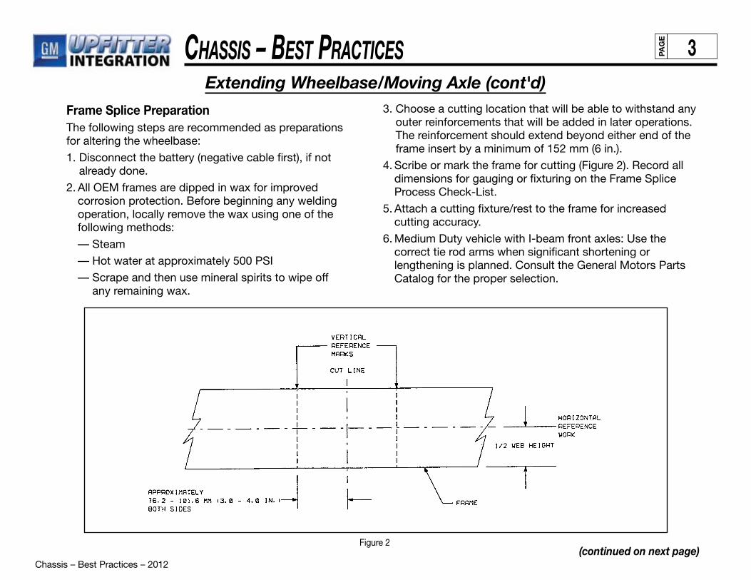
Chassis – Best Practices – 2012
Chassis – Best PraCtiCes 3PAG
E
Extending Wheelbase/Moving Axle (cont'd)
(continued on next page)
Frame Splice Preparation The following steps are recommended as preparations for altering the wheelbase:
1. Disconnect the battery (negative cable first), if not already done.
2. All OEM frames are dipped in wax for improved corrosion protection. Before beginning any welding operation, locally remove the wax using one of the following methods:
— Steam
— Hot water at approximately 500 PSI
— Scrape and then use mineral spirits to wipe off any remaining wax.
3. Choose a cutting location that will be able to withstand any outer reinforcements that will be added in later operations. The reinforcement should extend beyond either end of the frame insert by a minimum of 152 mm (6 in.).
4. Scribe or mark the frame for cutting (Figure 2). Record all dimensions for gauging or fixturing on the Frame Splice Process Check-List.
5. Attach a cutting fixture/rest to the frame for increased cutting accuracy.
6. Medium Duty vehicle with I-beam front axles: Use the correct tie rod arms when significant shortening or lengthening is planned. Consult the General Motors Parts Catalog for the proper selection.
Figure 2

Chassis – Best Practices – 2012
Chassis – Best PraCtiCes 4PAG
E
Extending Wheelbase/Moving Axle (cont'd)
(continued on next page)
Frame Splice Procedure Use the following procedure for splicing the frame:
1. Locate a specific frame splice cut location, observing the location guidelines already outlined. Cut the frame within the frame splice zone.
2. Grind cut edges of the frame smooth for line-to-line fit. This ensures a good fit and clean metal surface for the welding operation.
Frame inserts must be the same dimensional shape, metal gauge/thickness, material type and yield strength as the original frame side member.
3. Chamfer the outside edge of both the frame and the insert at a 30-degree angle, leaving 1/2 of the thickness (Figure 3).
4. Relocate rear frame section of the vehicle to install frame insert when lengthening.
5. Fixture and clamp the insert to ensure correct alignment (Figure 4). Make dimensional checks against predetermined reference marks (as shown earlier in Figure 2) to prevent possible error.
Figure 3
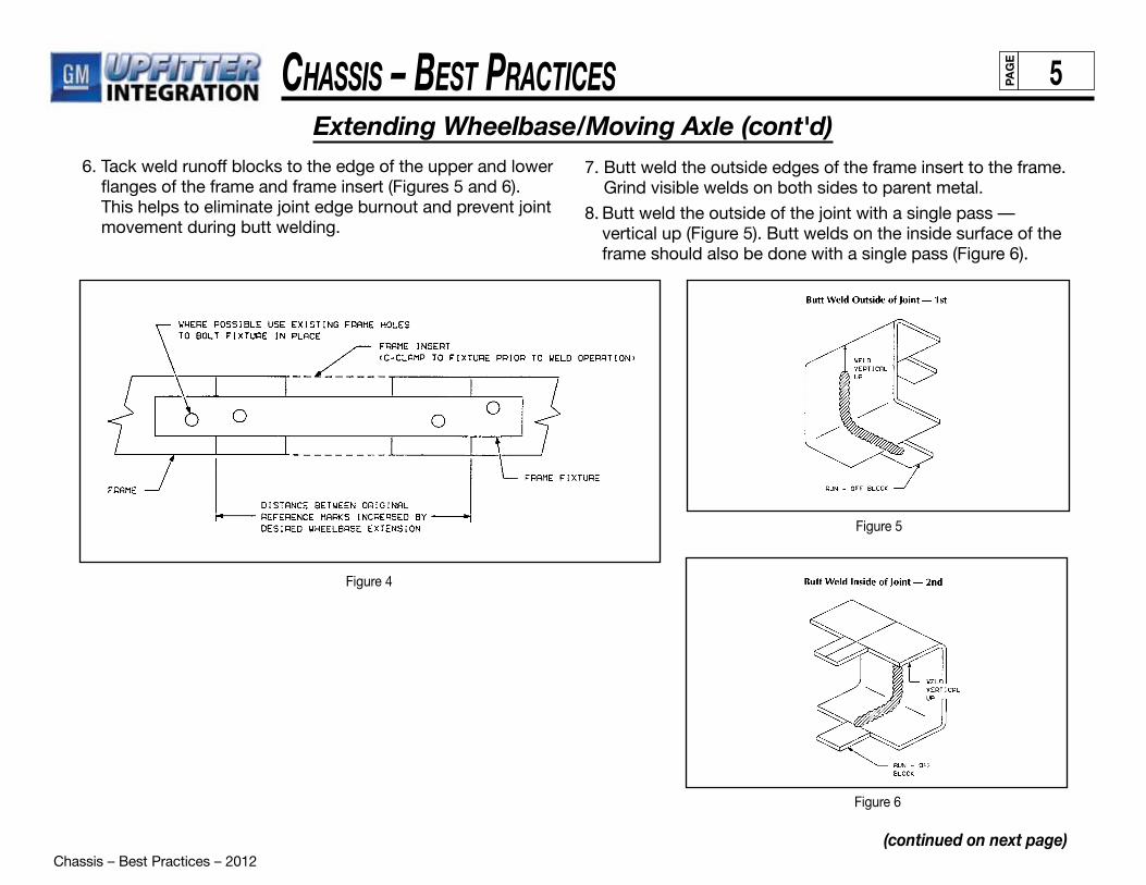
Chassis – Best Practices – 2012
Chassis – Best PraCtiCes 5PAG
E
Extending Wheelbase/Moving Axle (cont'd)
(continued on next page)
6. Tack weld runoff blocks to the edge of the upper and lower flanges of the frame and frame insert (Figures 5 and 6). This helps to eliminate joint edge burnout and prevent joint movement during butt welding.
7. Butt weld the outside edges of the frame insert to the frame. Grind visible welds on both sides to parent metal.
8. Butt weld the outside of the joint with a single pass — vertical up (Figure 5). Butt welds on the inside surface of the frame should also be done with a single pass (Figure 6).
Figure 5
Figure 6
Figure 4
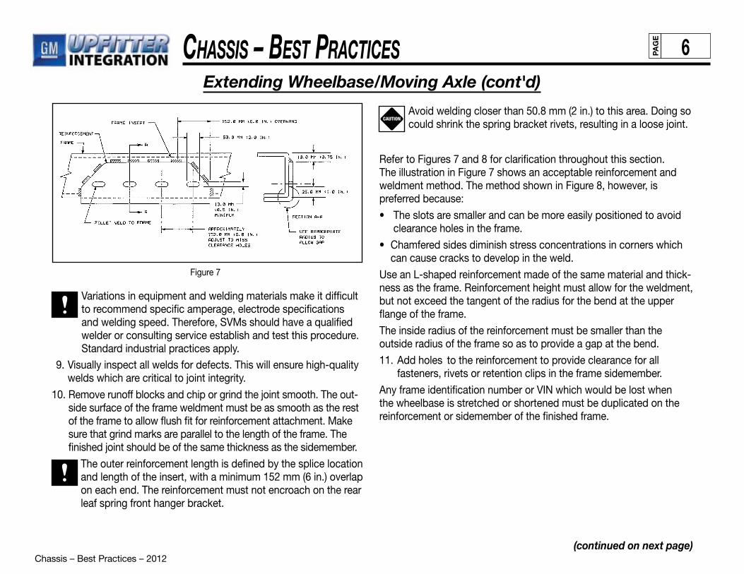
Chassis – Best Practices – 2012
Chassis – Best PraCtiCes 6PAG
E
Extending Wheelbase/Moving Axle (cont'd)
(continued on next page)
Figure 7
Variations in equipment and welding materials make it difficult to recommend specific amperage, electrode specifications and welding speed. Therefore, SVMs should have a qualified welder or consulting service establish and test this procedure. Standard industrial practices apply.
9. Visually inspect all welds for defects. This will ensure high-quality welds which are critical to joint integrity.
10. Remove runoff blocks and chip or grind the joint smooth. The out-side surface of the frame weldment must be as smooth as the rest of the frame to allow flush fit for reinforcement attachment. Make sure that grind marks are parallel to the length of the frame. The finished joint should be of the same thickness as the sidemember.
The outer reinforcement length is defined by the splice location and length of the insert, with a minimum 152 mm (6 in.) overlap on each end. The reinforcement must not encroach on the rear leaf spring front hanger bracket.
Avoid welding closer than 50.8 mm (2 in.) to this area. Doing so could shrink the spring bracket rivets, resulting in a loose joint.
Refer to Figures 7 and 8 for clarification throughout this section. The illustration in Figure 7 shows an acceptable reinforcement and weldment method. The method shown in Figure 8, however, is preferred because:
• The slots are smaller and can be more easily positioned to avoid clearance holes in the frame.
• Chamfered sides diminish stress concentrations in corners which can cause cracks to develop in the weld.
Use an L-shaped reinforcement made of the same material and thick-ness as the frame. Reinforcement height must allow for the weldment, but not exceed the tangent of the radius for the bend at the upper flange of the frame.
The inside radius of the reinforcement must be smaller than the outside radius of the frame so as to provide a gap at the bend.
11. Add holes to the reinforcement to provide clearance for all fasteners, rivets or retention clips in the frame sidemember.
Any frame identification number or VIN which would be lost when the wheelbase is stretched or shortened must be duplicated on the reinforcement or sidemember of the finished frame.
CAUTION

Chassis – Best Practices – 2012
Chassis – Best PraCtiCes 7PAG
E
Extending Wheelbase/Moving Axle (cont'd)
(continued on next page)
Secure the L-shaped reinforcement with clamps to the outside of the frame rail. There should be no visible gaps between the frame rail and the reinforcement other than at the bend. Fillet weld the reinforcement to the frame rail, using a skip weld technique. That is, a 50.8 mm (2 in.) weld followed by an equal space continuously along the span of the reinforcement.
Leave corners, bends and radii free to flex. Welding in these locations creates stress risers that can often lead to cracks in the weld.
Do not weld at the lower flange of the frame, either on the flange or at the edge.
For the final weld operation, fillet weld the reinforcement slots or holes to the frame. It is acceptable, but not necessary, to fillet weld the entire circumference of the slots or holes. Adding a fillet weld on the bottom half (180 degrees) only will provide sufficient strength.
After final welding, reapply undercoating to the exposed portion of the frame unless the area to be covered is closer than 305 mm (12 in.) from any exhaust component. For components falling within this area, use paint rather than undercoating to provide corrosion protection.
Extending The Frame (Rear Overhang)When lengthening rear frame extensions, SVMs must exercise great caution to avoid adversely affecting vehicle performance in the following areas:
• Excessive rear extensions allow customer opportunity to significantly unload the front end of the vehicle. This can result in customer dissatisfaction with vehicle braking and/or steering and handling.
• Rear frame extensions must be long enough to protect vulnerable components, such as fuel tanks, and short enough to avoid a negative effect on approach, departure and brake-over angles.
For guidelines on frame wax (corrosion protection) removal, refer to “Altering the Wheelbase” on page 3 in this section.
Figure 8
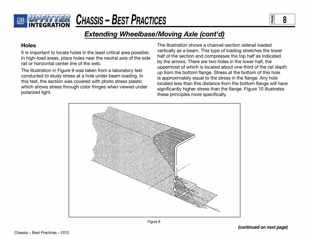
Chassis – Best Practices – 2012
Chassis – Best PraCtiCes 8PAG
E
Extending Wheelbase/Moving Axle (cont'd)
(continued on next page)
HolesIt is important to locate holes in the least critical area possible. In high-load areas, place holes near the neutral axis of the side rail or horizontal center line of the web.
The illustration in Figure 9 was taken from a laboratory test conducted to study stress at a hole under beam loading. In this test, the section was covered with photo stress plastic which shows stress through color fringes when viewed under polarized light.
The illustration shows a channel-section siderail loaded vertically as a beam. This type of loading stretches the lower half of the section and compresses the top half as indicated by the arrows. There are two holes in the lower half, the uppermost of which is located about one-third of the rail depth up from the bottom flange. Stress at the bottom of this hole is approximately equal to the stress in the flange. Any hole located less than this distance from the bottom flange will have significantly higher stress than the flange. Figure 10 illustrates these principles more specifically.
Figure 9

Chassis – Best Practices – 2012
Chassis – Best PraCtiCes 9PAG
E
Extending Wheelbase/Moving Axle (cont'd)
(continued on next page)
Figure 10
To avoid premature failure, SVMs should observe these general guidelines: • Use existing holes wherever possible.
• Locate holes no closer to the top or bottom flange than existing holes placed by the chassis manufacturer.
• Avoid placing holes in the lower one-third of the web in the area immediately behind the cab.
CrossmembersAdditional frame crossmembers are required whenever a two-or three-piece driveshaft is used to support the center bearing and shaft. Crossmember design should meet the following criteria:
• Adequate vertical stiffness to prevent resonance with prop shaft imbalance excitation in the vehicle speed range.
• Adequate strength to support the weight of the prop shaft and support bearing, with respect to maximum vertical acceleration of the prop shaft. (Note: Crossmember has adequate strength if stiffness requirement is met.)
• Crossmembers should be rigidly welded, bolted or riveted tothe frame rails.
• Designed to avoid retention and other foreign matter.
• Should not protrude excessively below the underbody and frame rails to prevent reduction in ramp break-over and ground clearances.
Chassis – Best Practices – 2012
Chassis – Best PraCtiCes 10PAG
E
Extending Wheelbase/Moving Axle (cont'd)
(continued on next page)
Analyzing Frame Failure CausesIn some cases, such as a vehicle collision, the reason for frame failure is easily apparent. In others, however, determining the cause is considerably more difficult. Frame failures can generally be traced to one of three reasons:
• Vehicle collision
• Excessive bending moment
• Localized stress concentration
CollisionsFailures caused by collisions should be repaired using proper methods and reinforcements as necessary.
Excessive Bending MomentOverload, improper weight distribution or vehicle misapplication can cause excessive bending moment failures. This type of failure occurs at different areas on different types of vehicles.
Localized Stress ConcentrationLocalized stress concentration failures may result from bending moment stresses. However, stress levels would not be high enough to cause any difficulty without localized stress concentration points. Localized stress concentration points maybe caused by:
• poor body or fifth wheel mountings
• special equipment or accessory installation
• improper welding or welding methods
• improper reinforcements
• loose bolts or rivets
• defective material
They may also result from high bending loads, coupled with severe torsional loads (e.g., off-road applications).
Fifth Wheel Installation
General Motors recommends attaching fifth wheel or body mounting to the frame rail web section, not through flanges. Refer to the GM Body Builders Manual for proper installation procedures.
Using U-bolts to attach fifth wheels or bodies is not an approved installation method. Doing so may result in the development of high-stress concentration.
Special Equipment/Accessory Installation
Installing special equipment or accessories can cause high-stress concentrations due to the attachment method or their added weight.
• Never drill holes through flanges.
• Avoid drastic changes to section modulus. Section modulus changes usually occur when large mounting plates are added to support special equipment.
• Avoid mounting heavy equipment across the flanges or on side-rail webs. Doing so may result in stress concentration high enough to cause failure of the nearest crossmember, bracket or other frame stiffener or through a nearby hole in the frame flange.
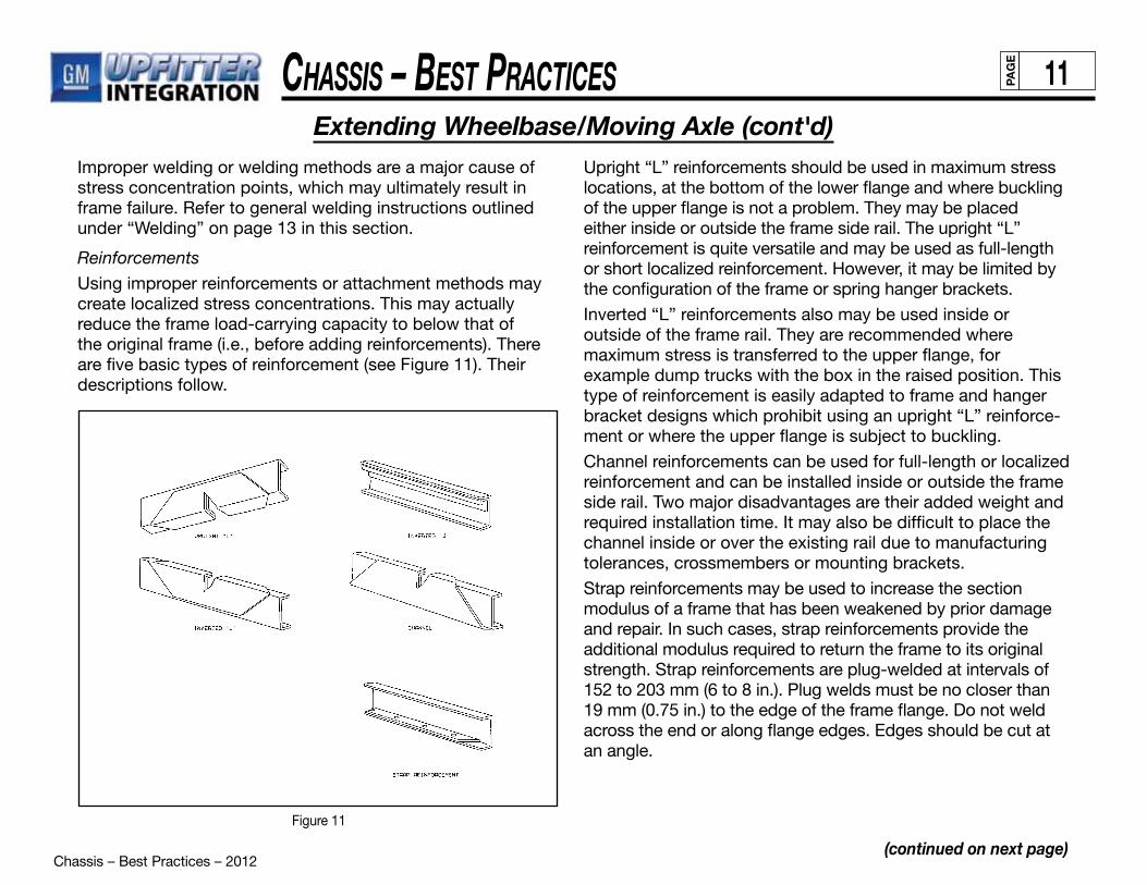
Chassis – Best Practices – 2012
Chassis – Best PraCtiCes 11PAG
E
Extending Wheelbase/Moving Axle (cont'd)
(continued on next page)
Improper welding or welding methods are a major cause of stress concentration points, which may ultimately result inframe failure. Refer to general welding instructions outlined under “Welding” on page 13 in this section.
Reinforcements
Using improper reinforcements or attachment methods may create localized stress concentrations. This may actually reduce the frame load-carrying capacity to below that of the original frame (i.e., before adding reinforcements). There are five basic types of reinforcement (see Figure 11). Their descriptions follow.
Figure 11
Upright “L” reinforcements should be used in maximum stress locations, at the bottom of the lower flange and where buckling of the upper flange is not a problem. They may be placed either inside or outside the frame side rail. The upright “L” reinforcement is quite versatile and may be used as full-length or short localized reinforcement. However, it may be limited by the configuration of the frame or spring hanger brackets.
Inverted “L” reinforcements also may be used inside or outside of the frame rail. They are recommended where maximum stress is transferred to the upper flange, for example dump trucks with the box in the raised position. This type of reinforcement is easily adapted to frame and hangerbracket designs which prohibit using an upright “L” reinforce-ment or where the upper flange is subject to buckling.
Channel reinforcements can be used for full-length or localized reinforcement and can be installed inside or outside the frame side rail. Two major disadvantages are their added weight and required installation time. It may also be difficult to place the channel inside or over the existing rail due to manufacturing tolerances, crossmembers or mounting brackets.
Strap reinforcements may be used to increase the section modulus of a frame that has been weakened by prior damage and repair. In such cases, strap reinforcements provide the additional modulus required to return the frame to its originalstrength. Strap reinforcements are plug-welded at intervals of 152 to 203 mm (6 to 8 in.). Plug welds must be no closer than 19 mm (0.75 in.) to the edge of the frame flange. Do not weld across the end or along flange edges. Edges should be cut atan angle.
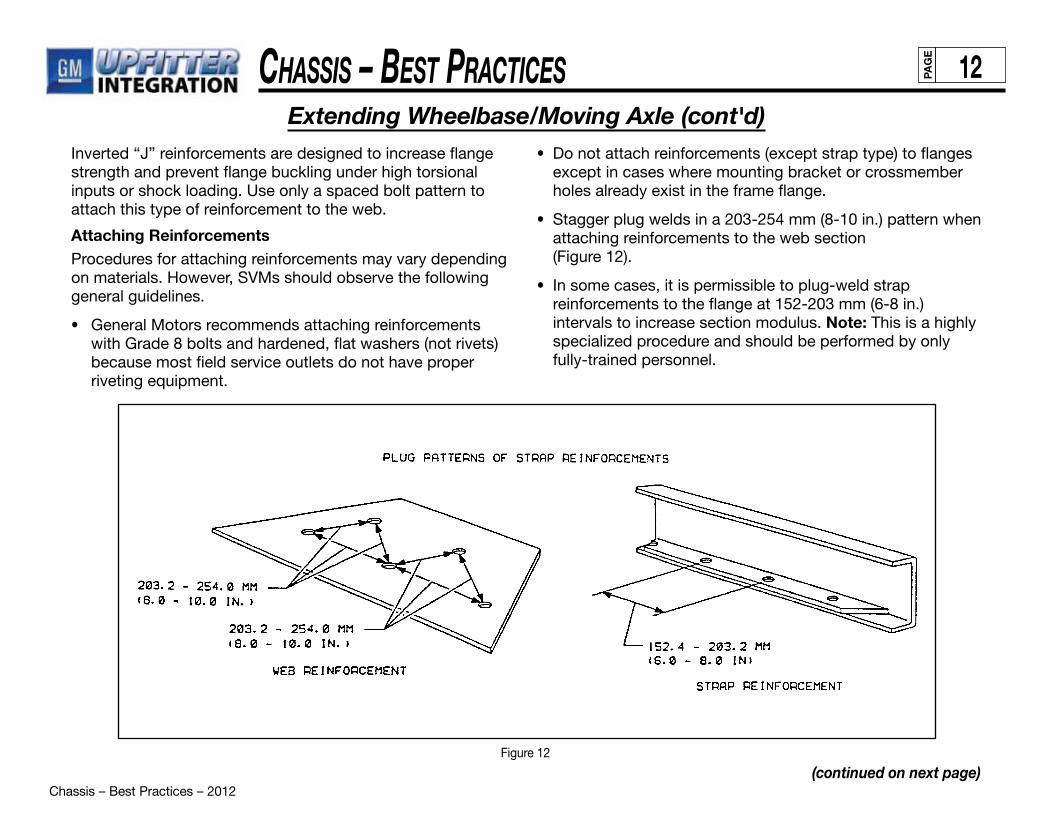
Chassis – Best Practices – 2012
Chassis – Best PraCtiCes 12PAG
E
(continued on next page)
Extending Wheelbase/Moving Axle (cont'd)Inverted “J” reinforcements are designed to increase flange strength and prevent flange buckling under high torsional inputs or shock loading. Use only a spaced bolt pattern to attach this type of reinforcement to the web.
Attaching ReinforcementsProcedures for attaching reinforcements may vary depending on materials. However, SVMs should observe the following general guidelines.
• General Motors recommends attaching reinforcements with Grade 8 bolts and hardened, flat washers (not rivets) because most field service outlets do not have proper riveting equipment.
• Do not attach reinforcements (except strap type) to flanges except in cases where mounting bracket or crossmember holes already exist in the frame flange.
• Stagger plug welds in a 203-254 mm (8-10 in.) pattern when attaching reinforcements to the web section (Figure 12).
• In some cases, it is permissible to plug-weld strap reinforcements to the flange at 152-203 mm (6-8 in.) intervals to increase section modulus. Note: This is a highly specialized procedure and should be performed by only fully-trained personnel.
Figure 12
Chassis – Best Practices – 2012
Chassis – Best PraCtiCes 13PAG
E
(continued on next page)
Extending Wheelbase/Moving Axle (cont'd)Terminating ReinforcementsTo prevent localized stress concentration, reinforcements must be properly terminated. Reinforcement ends must be tapered or stress relieved. Tapers should not exceed 45 degrees.
When using several reinforcements together, stagger them so that their ends overlap by 203-255 mm (8-10 in.).
Frame Repair and Reinforcement: General RulesSpecific frame repair and reinforcement procedures vary depending on circumstances and materials. The general guidelines outlined here, however, are very important and apply to virtually all repair and reinforcement situations.
• Always identify the material that makes up the base rail. Reinforcement should be of the same or better material than the base rail.
• Make sure that only fully trained, qualified specialists perform frame straightening and other repairs.
• Always try to identify the cause of the failure.
• Do not attach fifth wheels or body and accessory mountings through frame flanges. Refer to GM Body Builders Manual for additional information.
• Do not drill holes in top or lower flanges.
• Use only proper electrodes as specified for base rail material when welding is necessary.
• Do not use oxyacetylene welding equipment on frames.
• Do not weld reinforcements across the frame flanges.
• Do not weld within 19 mm (0.75 in.) of the edge of aframe flange.
• Remove all notches or weld buildups from flange edge when repairing a broken frame.
• Do not weld cast brackets to frame.
• Do not weld flanges of cracked reinforcements and base rails together.
• Do not patch cracks. Make correct repair and reinforcethe area.
• Always scarf reinforcement ends to provide adequate stress relief.
• Always stagger ends of reinforcements by a minimum of 203 mm (8 in.) apart.
• Before welding, disconnect negative battery cable to prevent possible electrical damage to generating system.
WeldingWelding is an excellent attachment or repairmethod. SVMs, however, must be very careful touse proper welding procedures. Inferior welds andimproper methods can cause further frame damageand additional reinforcements may be requiredlater to prevent the problem from reccurring. Referto the specifications table in Figure 13 for properwelding electrode identification and usage.
Prior to any welding, disconnect all negative (ground) cable(s) from all battery(ies).WARNING
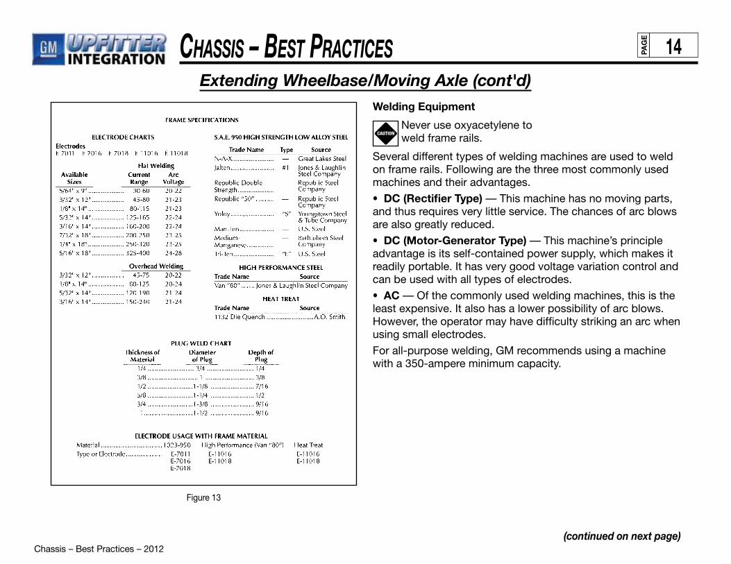
Chassis – Best Practices – 2012
Chassis – Best PraCtiCes 14PAG
E
(continued on next page)
Extending Wheelbase/Moving Axle (cont'd)
Figure 13
Welding Equipment
Never use oxyacetylene toweld frame rails.
Several different types of welding machines are used to weld on frame rails. Following are the three most commonly used machines and their advantages.
• DC (Rectifier Type) — This machine has no moving parts, and thus requires very little service. The chances of arc blows are also greatly reduced.
• DC (Motor-Generator Type) — This machine’s principle advantage is its self-contained power supply, which makes it readily portable. It has very good voltage variation control and can be used with all types of electrodes.
• AC — Of the commonly used welding machines, this is the least expensive. It also has a lower possibility of arc blows. However, the operator may have difficulty striking an arc when using small electrodes.
For all-purpose welding, GM recommends using a machine with a 350-ampere minimum capacity.
CAUTION
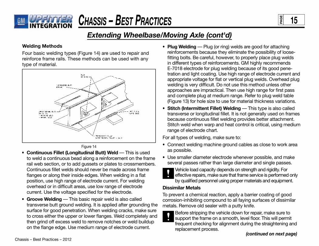
Chassis – Best Practices – 2012
Chassis – Best PraCtiCes 15PAG
E
Welding MethodsFour basic welding types (Figure 14) are used to repair and reinforce frame rails. These methods can be used with any type of material.
Figure 14
(continued on next page)
Extending Wheelbase/Moving Axle (cont'd)
• Continuous Fillet (Longitudinal Butt) Weld — This is used to weld a continuous bead along a reinforcement on the frame rail web section, or to add gussets or plates to crossmembers. Continuous fillet welds should never be made across frame flanges or along their inside edges. When welding in a flat position, use high range of electrode current. For welding overhead or in difficult areas, use low range of electrode current. Use the voltage specified for the electrode.
• Groove Welding — This basic repair weld is also called transverse butt ground welding. It is applied after grounding the surface for good penetration. When welding cracks, make sure to cross either the upper or lower flanges. Weld completely and then grind off excess weld to remove notches or weld buildup on the flange edge. Use medium range of electrode current.
• Plug Welding — Plug (or ring) welds are good for attaching reinforcements because they eliminate the possibility of loose-fitting bolts. Be careful, however, to properly place plug welds in different types of reinforcements. GM highly recommends E-7018 electrode for plug welding because of its good pene- tration and light coating. Use high range of electrode current and appropriate voltage for flat or vertical plug welds. Overhead plug welding is very difficult. Do not use this method unless other approaches are impractical. Then use high range for first pass and complete plug at medium range. Refer to plug weld table (Figure 13) for hole size to use for material thickness variations.
• Stitch (Intermittent Fillet) Welding — This type is also called transverse or longitudinal fillet. It is not generally used on frames because continuous fillet welding provides better attachment. Stitch weld when warp and heat control is critical, using medium range of electrode chart.
For all types of welding, make sure to:
• Connect welding machine ground cables as close to work area as possible.
• Use smaller diameter electrode whenever possible, and make several passes rather than large diameter and single passes.
Vehicle load capacity depends on strength and rigidity. For effective repairs, make sure that frame service is performed only by qualified personnel using proper materials and equipment.
Dissimilar MetalsTo prevent a chemical reaction, apply a barrier coating of good corrosion-inhibiting compound to all faying surfaces of dissimilar metals. Remove old sealer with a putty knife.
Before stripping the vehicle down for repair, make sure to support the frame on a smooth, level floor. This will permit frequent checking for alignment during the straightening and replacement process.

Chassis – Best Practices – 2012
Chassis – Best PraCtiCes 16PAG
E
(continued on next page)
Extending Wheelbase/Moving Axle (cont'd)
Driveshaft (Propshaft) ExtensionThe driveshaft can be extended, using a single-length or multiple-piece driveshaft. It is important to develop and follow proper design and installation guidelines for this process.
Driveshaft Extension DesignThe most important objective is to design driveshaft extensions that efficiently transfer power from the transmission to the rear axle assembly (Figure 15). For higher durabilityand reliability, General Motors recommends using only graphite driveshafts manufactured with driveline tubing.
Figure 15
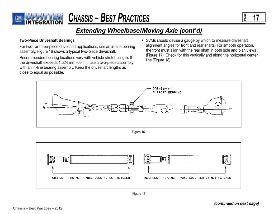
Chassis – Best Practices – 2012
Chassis – Best PraCtiCes 17PAG
E
(continued on next page)
Extending Wheelbase/Moving Axle (cont'd)Two-Piece Driveshaft BearingsFor two- or three-piece driveshaft applications, use an in-line bearing assembly. Figure 16 shows a typical two-piece driveshaft.
Recommended bearing locations vary with vehicle stretch length. If the driveshaft exceeds 1,524 mm (60 in.), use a two-piece assembly with an in-line bearing assembly. Keep the driveshaft lengths asclose to equal as possible.
Figure 16
Figure 17
• SVMs should devise a gauge by which to measure driveshaft alignment angles for front and rear shafts. For smooth operation, the front must align with the rear shaft in both side and plan views (Figure 17). Check for this vertically and along the horizontal center
line (Figure 18).
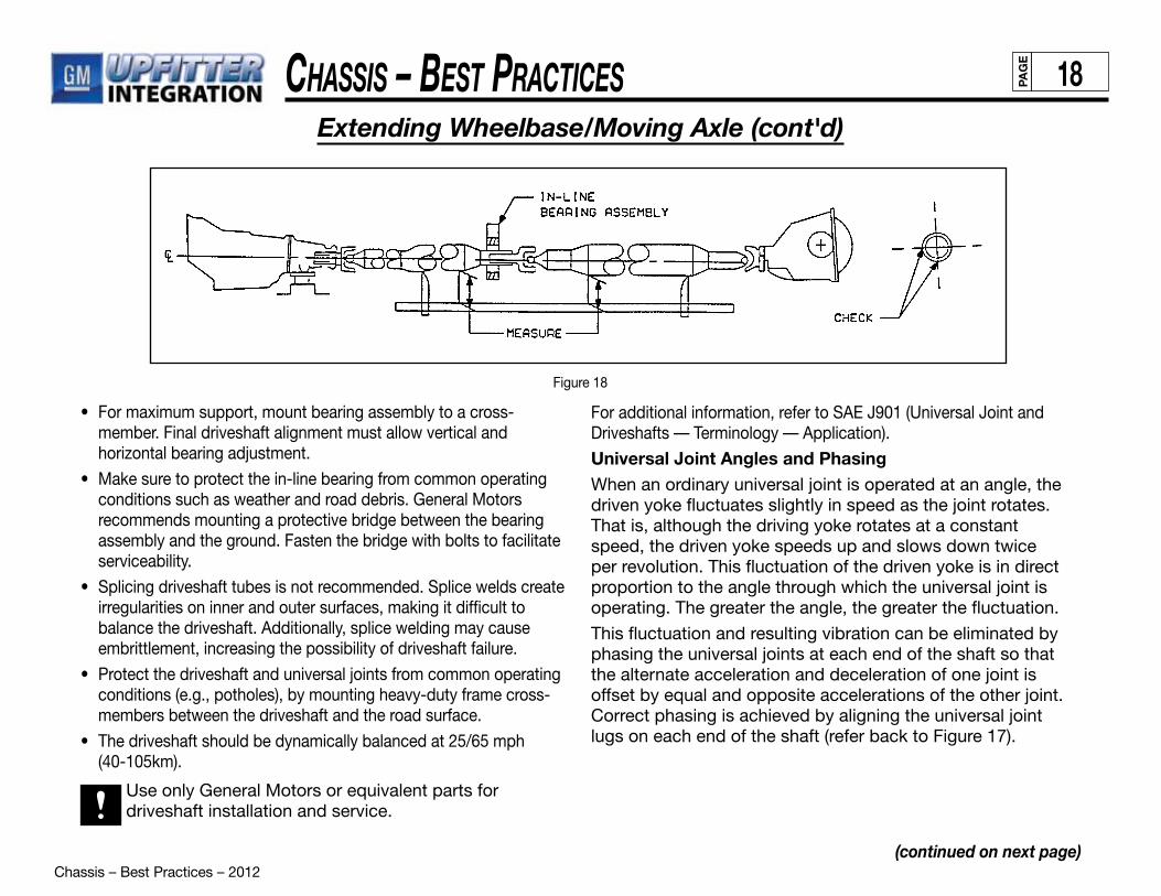
Chassis – Best Practices – 2012
Chassis – Best PraCtiCes 18PAG
E
Figure 18
(continued on next page)
Extending Wheelbase/Moving Axle (cont'd)
• For maximum support, mount bearing assembly to a cross-member. Final driveshaft alignment must allow vertical and horizontal bearing adjustment.
• Make sure to protect the in-line bearing from common operating conditions such as weather and road debris. General Motors recommends mounting a protective bridge between the bearing assembly and the ground. Fasten the bridge with bolts to facilitate serviceability.
• Splicing driveshaft tubes is not recommended. Splice welds create irregularities on inner and outer surfaces, making it difficult to
balance the driveshaft. Additionally, splice welding may cause embrittlement, increasing the possibility of driveshaft failure.
• Protect the driveshaft and universal joints from common operating conditions (e.g., potholes), by mounting heavy-duty frame cross-members between the driveshaft and the road surface.
• The driveshaft should be dynamically balanced at 25/65 mph (40-105km).
Use only General Motors or equivalent parts for driveshaft installation and service.
For additional information, refer to SAE J901 (Universal Joint and Driveshafts — Terminology — Application).
Universal Joint Angles and PhasingWhen an ordinary universal joint is operated at an angle, the driven yoke fluctuates slightly in speed as the joint rotates. That is, although the driving yoke rotates at a constant speed, the driven yoke speeds up and slows down twice per revolution. This fluctuation of the driven yoke is in direct proportion to the angle through which the universal joint is operating. The greater the angle, the greater the fluctuation.
This fluctuation and resulting vibration can be eliminated by phasing the universal joints at each end of the shaft so that the alternate acceleration and deceleration of one joint is offset by equal and opposite accelerations of the other joint. Correct phasing is achieved by aligning the universal jointlugs on each end of the shaft (refer back to Figure 17).
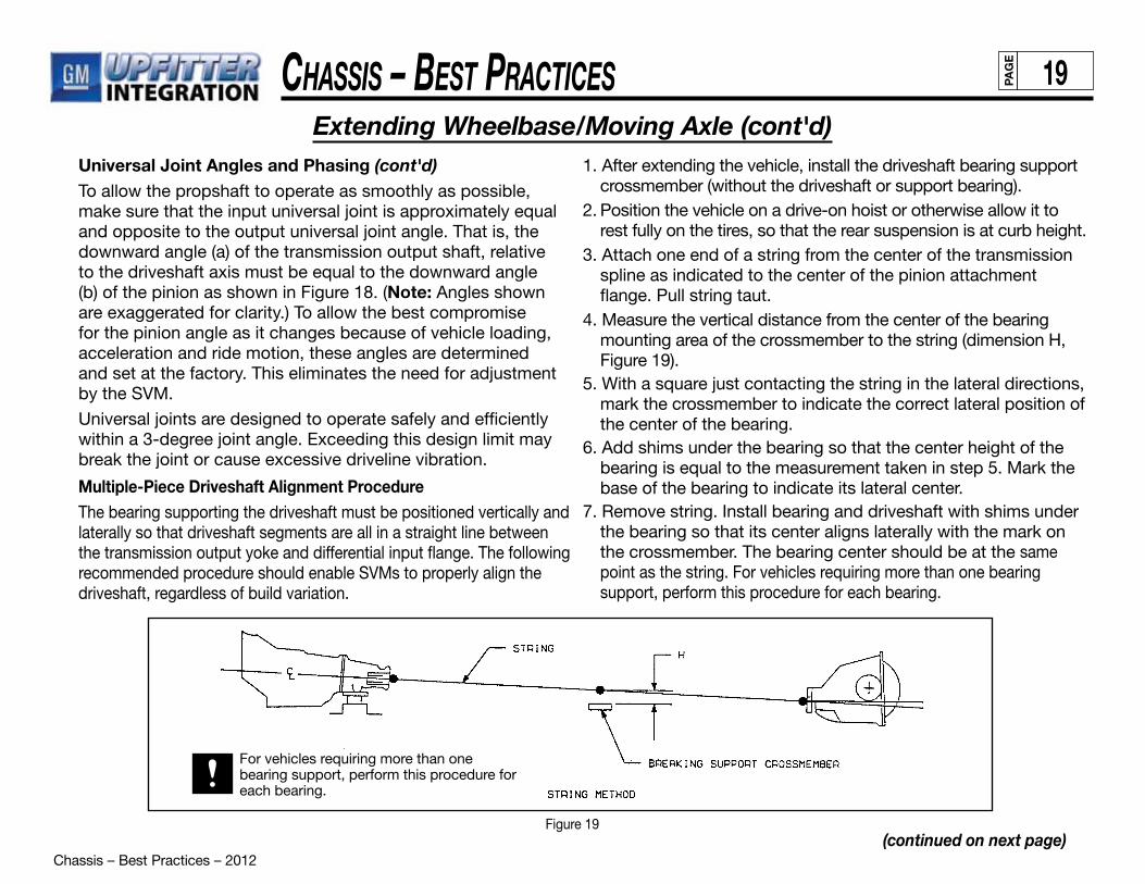
Chassis – Best Practices – 2012
Chassis – Best PraCtiCes 19PAG
E
Universal Joint Angles and Phasing (cont'd)To allow the propshaft to operate as smoothly as possible, make sure that the input universal joint is approximately equal and opposite to the output universal joint angle. That is, the downward angle (a) of the transmission output shaft, relative to the driveshaft axis must be equal to the downward angle (b) of the pinion as shown in Figure 18. (Note: Angles shown are exaggerated for clarity.) To allow the best compromise for the pinion angle as it changes because of vehicle loading, acceleration and ride motion, these angles are determinedand set at the factory. This eliminates the need for adjustment by the SVM.
Universal joints are designed to operate safely and efficiently within a 3-degree joint angle. Exceeding this design limit may break the joint or cause excessive driveline vibration.
(continued on next page)
Extending Wheelbase/Moving Axle (cont'd)
Figure 19
Multiple-Piece Driveshaft Alignment ProcedureThe bearing supporting the driveshaft must be positioned vertically and laterally so that driveshaft segments are all in a straight line between the transmission output yoke and differential input flange. The following recommended procedure should enable SVMs to properly align the driveshaft, regardless of build variation.
1. After extending the vehicle, install the driveshaft bearing support crossmember (without the driveshaft or support bearing).2. Position the vehicle on a drive-on hoist or otherwise allow it to rest fully on the tires, so that the rear suspension is at curb height.3. Attach one end of a string from the center of the transmission spline as indicated to the center of the pinion attachment flange. Pull string taut.4. Measure the vertical distance from the center of the bearing mounting area of the crossmember to the string (dimension H, Figure 19).5. With a square just contacting the string in the lateral directions, mark the crossmember to indicate the correct lateral position of the center of the bearing.6. Add shims under the bearing so that the center height of the bearing is equal to the measurement taken in step 5. Mark the base of the bearing to indicate its lateral center.7. Remove string. Install bearing and driveshaft with shims under the bearing so that its center aligns laterally with the mark on the crossmember. The bearing center should be at the same point as the string. For vehicles requiring more than one bearing support, perform this procedure for each bearing.
For vehicles requiring more than one bearing support, perform this procedure for each bearing.

Chassis – Best Practices – 2012
Chassis – Best PraCtiCes 20PAG
E
(continued on next page)
Body Mounting
Figure 20
Optimum body-mount location varies by frame wheelbase length. The best locations, for effective isolation from road vibration, are those closest to frame crossmembers and underbody crossbars. For optimum load-distribution isolation, additional body mounts should be no farther apart than762 mm (30 in.). When designing and locating body mounts, SVMs should also consider serviceability and the recom-mendations outlined in the “General Requirements” section that follows.
General RequirementsTo maintain base vehicle performance, it may be necessary to add, change or move body mounts along the frame. General Motors recommends the following practices for SVM-added body mounts:• Use only GM or equivalent body mounts. Use OEM rubber
body isolators, frame/body rails and/or outrigger brackets on the frame vertical side web.
• Avoid mounting bodies directly to the top of the frame. Doing so restricts frame torsional flexibility. It may also promote body cracking and provide a direct path for chassis noise, vibration and harshness (NVH). Figure 20 shows typical body mounts.
• Never weld body supports directly to the frame flanges. Do not weld body structures directly to frame extensions behind the rear suspension. Use consistent body attachment methods along the entire frame length.
• Use reinforcements or filler blocks where mounting devices may deform frame flanges. Mounting devices must be locked units that minimize loosening, but can be retightened if necessary. Use grade 8 PTN nuts.
• Correctly position all body mounts directly under cargo body crossmembers or longitudinal members to prevent body fatigue failures.
• Ambulance and other sensitive-cargo bodies require reduced stress on the body and frame. To accomplish this, minimize height above the frame and isolate the compartment from noise and vibration. Use full-floating, automotive style rubber body mounts or other chassis manufacturer-approved body mount systems. For bodies up to 3708 mm (146 in.) in length, install a minimum of four per side; for longer bodies, at least five per side.
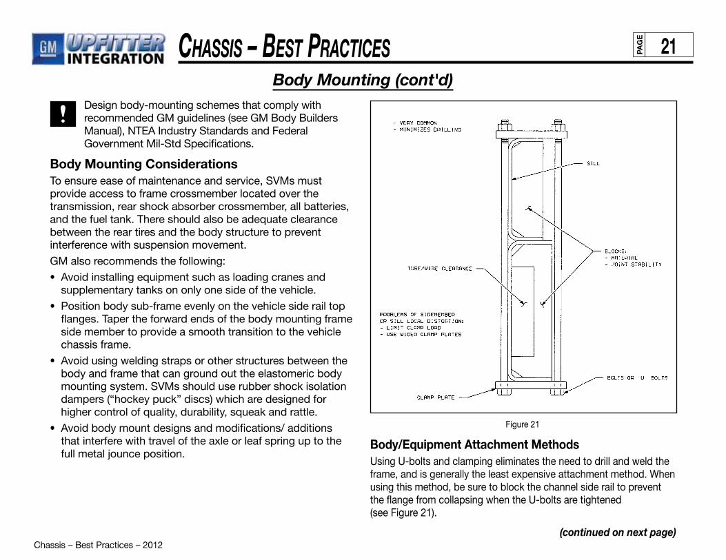
Chassis – Best Practices – 2012
Chassis – Best PraCtiCes 21PAG
E
(continued on next page)
Body Mounting (cont'd) Design body-mounting schemes that comply with
recommended GM guidelines (see GM Body Builders Manual), NTEA Industry Standards and Federal Government Mil-Std Specifications.
Body Mounting ConsiderationsTo ensure ease of maintenance and service, SVMs must provide access to frame crossmember located over the transmission, rear shock absorber crossmember, all batteries, and the fuel tank. There should also be adequate clearance between the rear tires and the body structure to prevent interference with suspension movement.
GM also recommends the following:
• Avoid installing equipment such as loading cranes and supplementary tanks on only one side of the vehicle.
• Position body sub-frame evenly on the vehicle side rail top flanges. Taper the forward ends of the body mounting frame side member to provide a smooth transition to the vehicle chassis frame.
• Avoid using welding straps or other structures between the body and frame that can ground out the elastomeric body mounting system. SVMs should use rubber shock isolation dampers (“hockey puck” discs) which are designed for higher control of quality, durability, squeak and rattle.
• Avoid body mount designs and modifications/ additions that interfere with travel of the axle or leaf spring up to the full metal jounce position.
Figure 21
Body/Equipment Attachment MethodsUsing U-bolts and clamping eliminates the need to drill and weld the frame, and is generally the least expensive attachment method. When using this method, be sure to block the channel side rail to prevent the flange from collapsing when the U-bolts are tightened(see Figure 21).

Chassis – Best Practices – 2012
Chassis – Best PraCtiCes 22PAG
E
(continued on next page)
Body Mounting (cont'd)
Figure 22
Use spacers between the subframe and the chassis frame as shown in Figure 22. Make sure that spacers do not interfere with plumbing or wiring routed along the frame rail and do not weld them to the frame flanges. Metal spacers are preferred as wood can shrink and drop out.
Clamping devices offer potential savings in both cost and installation time. Some equipment manufacturers have already incorporated clamped attachments into their designs because of these benefits. Since U-bolts and clamping devices depend on friction and a maintained clampingforce for attachment, a positive bolted connection should also be used for security.
Bolted attachments are generally preferred over welding because they retain more strength and are more easily serviced.
Body MountingSVMs should observe the following recommendationsfor body mounting:
• Use PTN fasteners instead of double nuts.
• Provide maintenance labels/decals wherever practical.
• Shear plates should be located at rear of frame rail and body longitudinal crossmember. Attachment, aft of rear spring rear shackle bracket.
• Use steel (not wood) anti-crush (fabricated vertical) spacers to protect flanges.
• Use Grade 8 bolts/PTN nuts on shear plates or weld (NOTE: DO NOT WELD IN HIGH-STRESS AREAS).
• Choose elastomeric rubber that meets critical damping requirements.
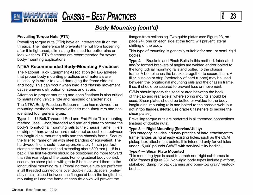
Chassis – Best Practices – 2012
Chassis – Best PraCtiCes 23PAG
E
Body Mounting (cont'd)Prevailing Torque Nuts (PTN)Prevailing torque nuts (PTN) have an interference fit on the threads. The interference fit prevents the nut from loosening after it is tightened, eliminating the need for cotter pins or lock washers. PTN fasteners are recommended for several body-mounting applications.
NTEA Recommended Body-Mounting PracticesThe National Truck Equipment Association (NTEA) advises that proper body mounting practices and materials are necessary in order to avoid damaging the frame side rail and body. This can occur when load and chassis movement cause uneven distribution of stress and strain.Attention to proper mounting and specifications is also critical to maintaining vehicle ride and handling characteristics.The NTEA Body Practices Subcommittee has reviewed the mounting methods of several chassis manufacturers and has identified four general types.Type 1 — U-Bolt/Threaded Rod and End Plate This mounting method uses U-bolt/threaded rod and end plate to secure the body’s longitudinal mounting rails to the chassis frame. Fillers or strips of hardwood or hard rubber act as cushions between the longitudinal mounting rails and the chassis frame. Secure the filler to frame or rail with steel banding or equivalent. The hardwood filler should taper approximately 1 inch per foot, starting at the front end and extending about 300 mm (11.8 in.) back. The first tie-down should be positioned no more forwardthan the rear edge of the taper. For longitudinal body control, secure the shear plates with grade 8 bolts or weld them to the longitudinal mounting rails. Prevailing torque nuts are preferred in all threaded connections over double nuts. Spacers (prefer-ably metal) placed between the flanges of both the longitudinal mounting rail and the frame at each tie-down will prevent the
flanges from collapsing. Two guide plates (see Figure 23, onpage 24), one on each side at the front, will prevent lateral shifting of the body.This type of mounting is generally suitable for non- or semi-rigid bodies.Type 2 — Brackets and Pinch Bolts In this method, fabricated and/or formed brackets of angles are welded and/or bolted to the longitudinal mounting rails and bolted to the chassisframe. A bolt pinches the brackets together to secure them. A filler, cushion or strip (preferably of hard rubber) may be used between the longitudinal mounting rails and the chassis frame. If so, it should be secured to prevent loss or movement.SVMs should specify the zone or area between the back of the cab and rear axle(s) where spring mounts should be used. Shear plates should be bolted or welded to the body longitudinal mounting rails and bolted to the chassis web, but not in top flanges. (Note: Use grade 8 fasteners to secure the shear plates.)Prevailing torque nuts are preferred in all threaded connections (instead of double nuts).Type 3 — Rigid Mounting (Service/Utility) This category includes industry practice of hard attachment to frame flanges using already existing holes, such as the OEM pickup box attachment points. It is intended only for vehicles under 15,000 pounds GVWR with service/utility bodies.Type 4 — Shear Plate Mounted This mounting type is used to attach non-rigid subframes to OEM frames (Figure 23). Non-rigid body types include platform, stakebed, dump, rollback carriers and open-top grain/livestock bodies.
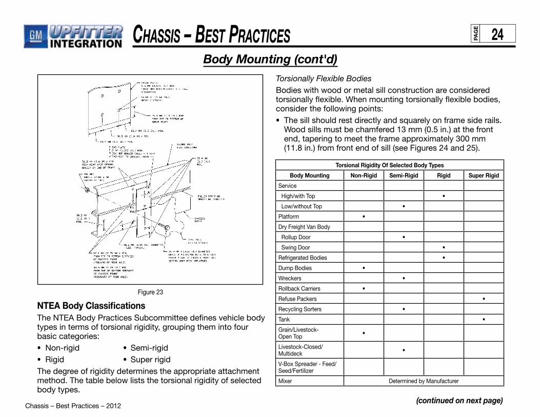
Chassis – Best Practices – 2012
Chassis – Best PraCtiCes 24PAG
E
(continued on next page)
Body Mounting (cont'd)
Figure 23
NTEA Body ClassificationsThe NTEA Body Practices Subcommittee defines vehicle body types in terms of torsional rigidity, grouping them into four basic categories:• Non-rigid • Semi-rigid• Rigid • Super rigidThe degree of rigidity determines the appropriate attachment method. The table below lists the torsional rigidity of selected body types.
Torsional Rigidity Of Selected Body Types
Body Mounting Non-Rigid Semi-Rigid Rigid Super Rigid
Service
High/with Top •
Low/without Top •
Platform •
Dry Freight Van Body
Rollup Door •
Swing Door •
Refrigerated Bodies •
Dump Bodies •
Wreckers •
Rollback Carriers •
Refuse Packers •
Recycling Sorters •
Tank •
Grain/Livestock-Open Top •
Livestock-Closed/Multideck •
V-Box Spreader - Feed/Seed/Fertilizer
Mixer Determined by Manufacturer
Torsionally Flexible BodiesBodies with wood or metal sill construction are considered torsionally flexible. When mounting torsionally flexible bodies, consider the following points:• The sill should rest directly and squarely on frame side rails.
Wood sills must be chamfered 13 mm (0.5 in.) at the front end, tapering to meet the frame approximately 300 mm (11.8 in.) from front end of sill (see Figures 24 and 25).

Chassis – Best Practices – 2012
Chassis – Best PraCtiCes 25PAG
E
(continued on next page)
Body Mounting (cont'd)
Figure 24
Figure 25
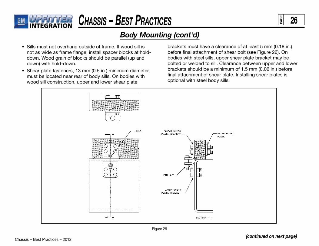
Chassis – Best Practices – 2012
Chassis – Best PraCtiCes 26PAG
E
(continued on next page)
Body Mounting (cont'd)
Figure 26
• Sills must not overhang outside of frame. If wood sill is not as wide as frame flange, install spacer blocks at hold-down. Wood grain of blocks should be parallel (up and down) with hold-down.
• Shear plate fasteners, 13 mm (0.5 in.) minimum diameter, must be located near rear of body sills. On bodies with wood sill construction, upper and lower shear plate
brackets must have a clearance of at least 5 mm (0.18 in.) before final attachment of shear bolt (see Figure 26). On bodies with steel sills, upper shear plate bracket may be bolted or welded to sill. Clearance between upper and lower brackets should be a minimum of 1.5 mm (0.06 in.) before final attachment of shear plate. Installing shear plates is optional with steel body sills.

Chassis – Best Practices – 2012
Chassis – Best PraCtiCes 27PAG
E
Figure 27
(continued on next page)
Body Mounting (cont'd)
Rabbet grooves at the top of longitudinal wood sills (Figure 27) to allow sheet metal channels of 1.7 mm or No. 14 gauge minimum at each mounting. Use 6 mm (0.25 in.) minimum flat plate. Metal channels or flat plate should extend approximately 25 mm (1 in.) beyond the clip plate.
• On non steel-sill bodies, use a hardwood spacer between the sill and frame side rail. The spacer must be at least 19 mm or 0.75 in. thick (i.e., chamfered 13 mm/0.5 in. at the front end, tapering to meet frame 300 mm/12 in.). A wood spacer is not necessary if steel sill body is used.
• Mountings must be spaced to clear suspension and any other parts attached to frame side rail. Use two long bolts, studs or U-bolts 13 mm (0.5 in.) minimum diameter for each mounting. One mounting should be located at the front end of sill (at or as close to rear end of taper
as possible), one near the rear end and others should be spaced as nearly equally as possible between front and rear mountings. Do not mutilate the frame side rails in any way to accommodate mountings.
• Use clip plates (approximately the same thickness as mounting bolt diameter) at top and bottom of mounting bolts. When U-bolts are used, the contour at top of the U-bolt should fit against the clip plate. Plate may be notched instead of using holes (refer back to Figure 25).
• Use a block of hard, dry wood with grain running up and down between flanges of frame side rail at each mounting. Block should extend beyond width of frame flanges and should be grooved. Mounting bolt fitted into groove will hold block in place. Where steel body sills are used, a similar block is required between sill flanges.
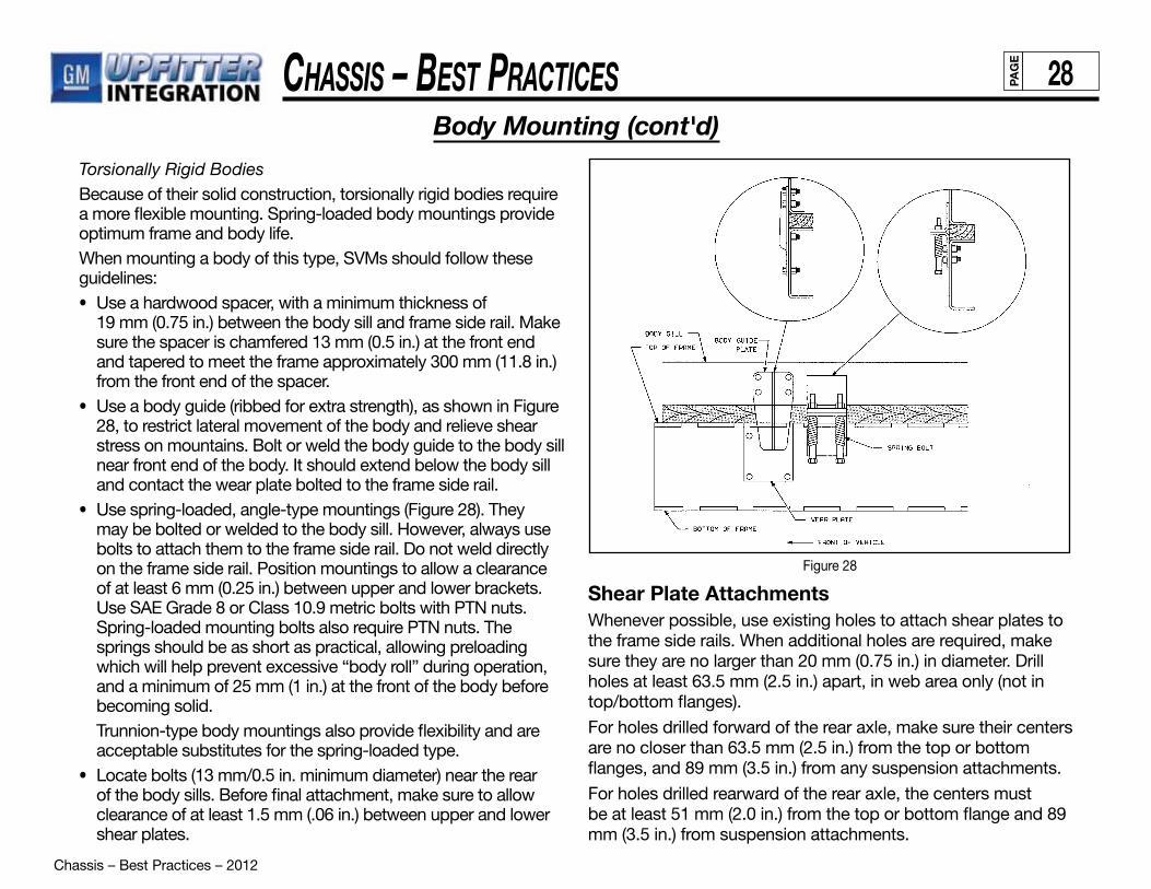
Chassis – Best Practices – 2012
Chassis – Best PraCtiCes 28PAG
E
Torsionally Rigid BodiesBecause of their solid construction, torsionally rigid bodies require a more flexible mounting. Spring-loaded body mountings provide optimum frame and body life.When mounting a body of this type, SVMs should follow these guidelines:• Use a hardwood spacer, with a minimum thickness of
19 mm (0.75 in.) between the body sill and frame side rail. Make sure the spacer is chamfered 13 mm (0.5 in.) at the front end and tapered to meet the frame approximately 300 mm (11.8 in.) from the front end of the spacer.
• Use a body guide (ribbed for extra strength), as shown in Figure 28, to restrict lateral movement of the body and relieve shear stress on mountains. Bolt or weld the body guide to the body sill near front end of the body. It should extend below the body sill and contact the wear plate bolted to the frame side rail.
• Use spring-loaded, angle-type mountings (Figure 28). They may be bolted or welded to the body sill. However, always use bolts to attach them to the frame side rail. Do not weld directly on the frame side rail. Position mountings to allow a clearance of at least 6 mm (0.25 in.) between upper and lower brackets. Use SAE Grade 8 or Class 10.9 metric bolts with PTN nuts. Spring-loaded mounting bolts also require PTN nuts. The springs should be as short as practical, allowing preloading which will help prevent excessive “body roll” during operation, and a minimum of 25 mm (1 in.) at the front of the body before becoming solid.
Trunnion-type body mountings also provide flexibility and are acceptable substitutes for the spring-loaded type.
• Locate bolts (13 mm/0.5 in. minimum diameter) near the rear of the body sills. Before final attachment, make sure to allow clearance of at least 1.5 mm (.06 in.) between upper and lower shear plates.
Body Mounting (cont'd)
Figure 28
Shear Plate AttachmentsWhenever possible, use existing holes to attach shear plates to the frame side rails. When additional holes are required, make sure they are no larger than 20 mm (0.75 in.) in diameter. Drill holes at least 63.5 mm (2.5 in.) apart, in web area only (not in top/bottom flanges).
For holes drilled forward of the rear axle, make sure their centers are no closer than 63.5 mm (2.5 in.) from the top or bottom flanges, and 89 mm (3.5 in.) from any suspension attachments.
For holes drilled rearward of the rear axle, the centers must be at least 51 mm (2.0 in.) from the top or bottom flange and 89 mm (3.5 in.) from suspension attachments.

Chassis – Best Practices – 2012
Chassis – Best PraCtiCes 29PAG
E
(continued on next page)
Fuel Systems
The fuel system includes the fuel tank, metering, lines (including purge control solenoids) and canister(s). Proper sealing is critical to the integrity and overall operation of the fuel system. The SVM assumes complete responsibility for any modifications or alterations to the fuel system. This includes responsibility for system reliability and performance as well as compliance to FMVSS 301 (CMVSS 301).
General Motors recommends that SVMs DO NOT ALTER THE FUEL SYSTEM IN ANY WAY. When delivered, the vehicle fuel evaporative emission control equipment is certified in compliance with Federal and California Vehicle Emission Standards. Any alteration to systems or components and their location could void compliance.
Systems include:• Fuel tank, metering unit, lines including purge control solenoids and canister or canisters.
Environment Includes:• Heat sources, heat shields, system component relocation.
Fuel FillGeneral Motors recommends the following fuel-fill guidelines:• Fuel tank filler pipe location should be so situated and constructed as to prevent gasoline vapor from emitting to vents of pilot flamed devices.
• Locate and mount the fuel tank filler pipe so as to prevent vapor from entering the body and engine compartment air inlets.• Maintain a clearance of at least 76 mm (3 in.) between the filler pipe/vent hose and body components.• Properly route and secure the filler pipe and vent hoses to prevent failure due to wear and fatigue.• Make sure that filler pipe/vent hose lines have a gravity fuel flow to the tank at all times.• Verify that there are no fuel traps in the filler pipe or vent hoses.• Make certain that any added hose is suitable for the type of fuel used (gasoline or diesel).• Provide a ground strap to ensure that electrical ground connection is made.• Alterations of fuel line routings could affect the completed vehicle and are, therefore, not desirable. The complete fuel system must comply with FMVSS 301 as well as Federal and C.A.R.B. vapor emission requirements. Fuel Fill / Vent pipe hoses should be trimmed to hose retaining beads (when present); hoses should be secured with approved hose clamps at proper torque specs. A minimum of 8.0 inches of fill hose should be maintained between the filler neck and the fuel tank interfaces. Fill pipe ends must be free of burrs. For additional information on Fuel Fill and Fuel Systems refer to the GM U.I. Body Builders Manual.
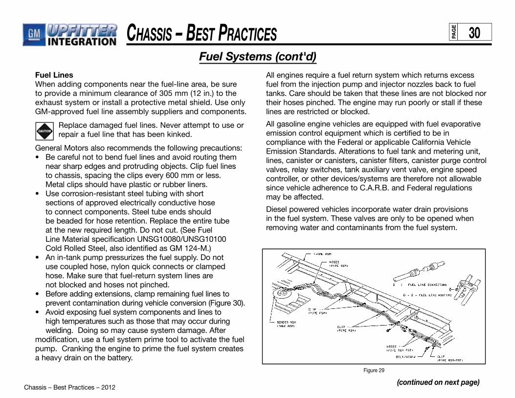
Chassis – Best Practices – 2012
Chassis – Best PraCtiCes 30PAG
E
(continued on next page)
Fuel Systems (cont'd)Fuel LinesWhen adding components near the fuel-line area, be sure to provide a minimum clearance of 305 mm (12 in.) to the exhaust system or install a protective metal shield. Use only GM-approved fuel line assembly suppliers and components.
Replace damaged fuel lines. Never attempt to use or repair a fuel line that has been kinked.
General Motors also recommends the following precautions:• Be careful not to bend fuel lines and avoid routing them near sharp edges and protruding objects. Clip fuel lines to chassis, spacing the clips every 600 mm or less. Metal clips should have plastic or rubber liners.• Use corrosion-resistant steel tubing with short sections of approved electrically conductive hose to connect components. Steel tube ends should be beaded for hose retention. Replace the entire tube at the new required length. Do not cut. (See Fuel Line Material specification UNSG10080/UNSG10100 Cold Rolled Steel, also identified as GM 124-M.)• An in-tank pump pressurizes the fuel supply. Do not use coupled hose, nylon quick connects or clamped hose. Make sure that fuel-return system lines are not blocked and hoses not pinched.• Before adding extensions, clamp remaining fuel lines to prevent contamination during vehicle conversion (Figure 30). • Avoid exposing fuel system components and lines to high temperatures such as those that may occur during welding. Doing so may cause system damage. After modification, use a fuel system prime tool to activate the fuel pump. Cranking the engine to prime the fuel system creates a heavy drain on the battery.
All engines require a fuel return system which returns excess fuel from the injection pump and injector nozzles back to fuel tanks. Care should be taken that these lines are not blocked nor their hoses pinched. The engine may run poorly or stall if these lines are restricted or blocked.
All gasoline engine vehicles are equipped with fuel evaporative emission control equipment which is certified to be in compliance with the Federal or applicable California Vehicle Emission Standards. Alterations to fuel tank and metering unit, lines, canister or canisters, canister filters, canister purge control valves, relay switches, tank auxiliary vent valve, engine speed controller, or other devices/systems are therefore not allowable since vehicle adherence to C.A.R.B. and Federal regulations may be affected.
Diesel powered vehicles incorporate water drain provisions in the fuel system. These valves are only to be opened when removing water and contaminants from the fuel system.
Figure 29
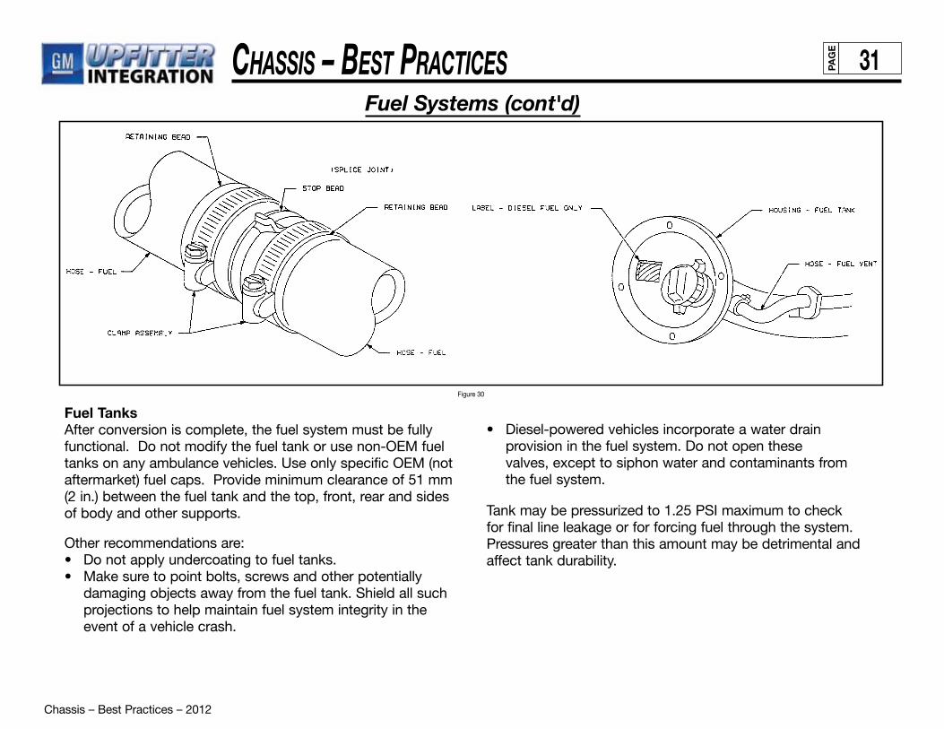
Chassis – Best Practices – 2012
Chassis – Best PraCtiCes 31PAG
E
Fuel Systems (cont'd)
Fuel TanksAfter conversion is complete, the fuel system must be fully functional. Do not modify the fuel tank or use non-OEM fuel tanks on any ambulance vehicles. Use only specific OEM (not aftermarket) fuel caps. Provide minimum clearance of 51 mm (2 in.) between the fuel tank and the top, front, rear and sides of body and other supports.
Other recommendations are:• Do not apply undercoating to fuel tanks.• Make sure to point bolts, screws and other potentially damaging objects away from the fuel tank. Shield all such projections to help maintain fuel system integrity in the event of a vehicle crash.
• Diesel-powered vehicles incorporate a water drain provision in the fuel system. Do not open these valves, except to siphon water and contaminants from the fuel system.
Tank may be pressurized to 1.25 PSI maximum to check for final line leakage or for forcing fuel through the system. Pressures greater than this amount may be detrimental and affect tank durability.
Figure 30

Chassis – Best Practices – 2012
Chassis – Best PraCtiCes 32PAG
E
Diesel Exhaust Fluid (DEF) System
The Upfitter is responsible for any modifications to the DEF system.
Tank Placement • Tank movement is not recommended. • GM has validated the system durability only in the positions as purchased.• The existing DEF tank mounting hardware can not be altered. • DEF tank/line surface temps cannot exceed 70C, proper shielding is required.• The DEF tank can not be mounted in a manner which locates the bottom surface of the tank below the frame rail.• DEF tanks do not have a drain. Service procedure must be followed if contaminated. (remove and drain).• DEF Tank cannot be moved on full body vehicles (FMVSS301).
Def Fill Hose Assembly• Increasing the length not recommended. • Shorten from tank end is preferred. • DEF fill location to always be above tank, gravity fed 4 degree angle (min.) with minimal bends.
Fluid Delivery Line• This line is heated, do not cut or adjust length. • Carefully coil any extra line and secure to maintain the “as shipped” heated line length. (Use GM clip part #25952656)
Wire Harness• Do not change/modify the wire harnesses on the DEF tank. • Carefully coil any extra line and secure.
Auxiliary Fuel TanksThe use of auxiliary fuel tanks is not recommended. If an auxiliary fuel tank is added, the alterer must take responsibility for compliance with affected motor vehicle safety and emission standards. Also, if an auxiliary fuel tank is added to a gasoline-powered vehicle, the fuel must be drawn through a pipe at the top of the tank (balance line between tanks is not permitted). Venting of auxiliary tank to be provided via purge canister and not to atmosphere. Gasoline fueled vehicles are now equipped with a fuel pump return line. If an auxiliary tank is added, the tank selector valve must include a port which returns fuel to the tank from which the fuel is being drawn. Similarly, addition of another fuel line for an auxiliary fuel user (such as a generator) will require emission revalidation.
In gasoline engines the fuel pump is located in the fuel tank. The battery must be disconnected before starting any work on the fuel system.
Auxillary Fuel Tanks & Diesel Exhaust Fluid (DEF) System

Chassis – Best Practices – 2012
Chassis – Best PraCtiCes 33PAG
E
Brakes General RequirementsSVMs must ensure that the brake system functions properly after conversion is complete. Modifying or altering the brake system may require the SVM to recertify compliance with FVMSS 105 and CMVSS 105.
Modifications may also adversely affect the vehicle’s braking capacity. Avoid designs, such as special ground-effects packages, which may prevent proper ventilation of the brake system. Also avoid changing the brake main cylinder location,
Federal Standards and RegulationsBrake systems must conform to all federal motor vehicle safety standards and regulations, including:
• FMVSS/CMVSS 105: Hydraulic Service Brake Normal, Emergency and Parking Brake Performance
• FMVSS/CMVSS 106: Brake Hoses — Hydraulic, Airand Vacuum
• FMVSS/CMVSS 116: Motor Vehicle Brake Fluids For additional information, refer to the following SAE specifications:
• SAE J1401: Road Vehicle — Hydraulic Brake Hose Assembly Use with Non-Petroleum Base Hydraulic Fluids
• SAE J1288: Packaging, Storage and Shelf Life of Hydraulic Brake Hose Assemblies
• SAE J1403: Vacuum Brake Hose
• SAE J1406: Application of Hydraulic Brake Hose toMotor Vehicles
Modification ChecklistFor vehicle-specific diagnostic, inspection and service guidelines, refer to the appropriate GM Service Manual. The following checklist will also help SVMs to ensure proper brake system operation after modification.
• Do not splice the park-brake cable.
• Make sure the hydraulic brake system is free of air and hydraulic leaks. Bleed brakes if necessary.
• Ensure that the vacuum booster system or hydroboost system is functional and free of leaks.
• Check the master cylinder fluid level. Fill as necessary.
• Check the power steering fluid level on vehicles equipped with hydroboost brake.
• Make sure that added floor carpeting does not restrict service or parking brake pedal travel.
• Provide at least 51 mm (2 in.) clearance between body- or chassis-mounted components and brake hoses.
• Never change the brake main cylinder location, brake pedal pushrod length or pedal position.
• Verify that the brake warning switch is operative.
• Do not add suspension accessories or make any modification that will change axle loads or trim height. Such changes may provide a false reading to the brake proportioning valve.
• Vehicle weight, weight distribution and center of gravity determine the appropriate proportioning valve.
(continued on next page)
Brakes
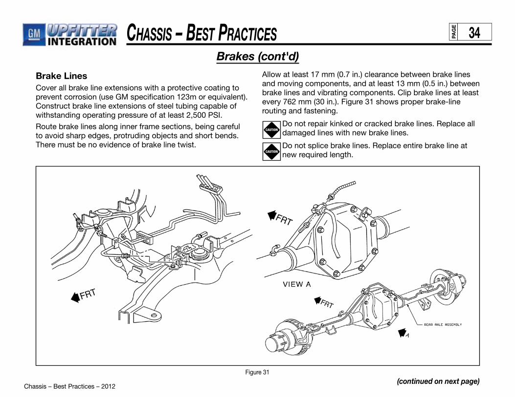
Chassis – Best Practices – 2012
Chassis – Best PraCtiCes 34PAG
E
Allow at least 17 mm (0.7 in.) clearance between brake lines and moving components, and at least 13 mm (0.5 in.) between brake lines and vibrating components. Clip brake lines at least every 762 mm (30 in.). Figure 31 shows proper brake-line routing and fastening.
Do not repair kinked or cracked brake lines. Replace all damaged lines with new brake lines.
Do not splice brake lines. Replace entire brake line at new required length.
Brake LinesCover all brake line extensions with a protective coating to prevent corrosion (use GM specification 123m or equivalent). Construct brake line extensions of steel tubing capable of withstanding operating pressure of at least 2,500 PSI.
Route brake lines along inner frame sections, being careful to avoid sharp edges, protruding objects and short bends. There must be no evidence of brake line twist.
CAUTION
CAUTION
(continued on next page)
Brakes (cont'd)
Figure 31

Chassis – Best Practices – 2012
Chassis – Best PraCtiCes 35PAG
E
(continued on next page)
Brakes (cont'd)
Figure 32
Parking Brake SystemsIf so equipped, the vehicle’s mechanical parking brake system with automatic vacuum release consists of parking brake pedal assembly, vacuum diaphragm, cables and connectors (Figure 32). The parking brake system should be able to withstand at least 400 lbs. of cable tension. General Motors recommends using a one-piece parking brake cable assembly consistent with the base vehicle. For adjustment and testing procedures following installation, refer to the appropriate GM Service Manual.
Avoid special vehicle designs (e.g., ground-effects packages) that may prevent proper brake system ventilation. Lack of ventilation may lead to shortened brake life.
Additional recommendations are:
• Allow at least 17 mm (0.7 in.) clearance between brake lines and moving components (e.g., steering shaft, shift levers, etc.).
• Allow 13 mm (0.5 in.) clearance between brake pipes and vibrating parts (e.g., front sheet metal, underbody and power brake booster) unless pipes are clipped to these components.
• Use brake line clips spaced at intervals no greater than 762 mm (30 in.).
Do not splice parking brake cable. Replace with new cable at required length only.CAUTION
Chassis – Best Practices – 2012
Chassis – Best PraCtiCes 36PAG
E
(continued on next page)
Brakes (cont'd)
Electronic Dynamic Rear Proportioning (DRP)Electronic Dynamic Rear Proportioning (DRP) allows better utilization of the rear brakes, which reduces brake wear. More over, this better balancing of the brake system as a whole improves brake performance.
Benefits include:
• Good balance with front brakes when truck is heavily loaded or under towing/trailering conditions
• Provides maximum braking forces at rear wheels
• Provides maximum braking forces when braking on an uneven road surface, such as a washboard at an intersection
• Reduced front brake wear
• Better use of rear brakes
• Improved braking performance
Since changes in vehicle mass, mass distribution,and center of gravity determine the appropriateproportioning, the altered vehicle must not exceedGVWR, front and rear GAWR, and stay within theallowable center of gravity range.

Chassis – Best Practices – 2012
Chassis – Best PraCtiCes 37PAG
E
(continued on next page)
Exhaust SystemSVMs must be careful to use components and follow procedures that will prevent exhaust fumes from entering any occupant area. Observe the following guidelines:
• Seal all holes and openings through the floor and body.
• Make sure exhaust discharge is unobstructed and directed away from passenger areas.
• With the vehicle in motion, test the tailpipe outlet location to ensure that fumes do not enter the passenger compartment.
Altering the exhaust outlet or its position, and removal or alteration of noise abatement components may place the vehicle in violation of federal, state or local noise laws. The SVM may have to recertify vehicle compliance with federal, state and local noise emission requirements.
The SVM must assume full responsibility for complying with Environmental Protection Agency (EPA) noise regulations if the exhaust system is modified.
The U.S. Environmental Protection Agency (EPA) has established noise emission standards applicable to vehicles (in general vehicles in excess of 10,000 pounds GVWR capable of transportation of property on a street or highway) manufactured after January 1, 1978, under the provisions of the Noise Control Act of 1972. The standards provide that vehicles manufactured after January 1, 1978, when tested pursuant to EPA’s prescribed test procedure, must conform to an 83 dBA level and vehicles manufactured after January 1, 1988 must conform to an 80 dBA level.
The Act and the standards impose legal obligations on vehicle manufacturers and subsequent manufacturers.Questions dealing with what is covered under the definition of
a “vehicle” in the standards and the specific application of the Act or the standards to your business should be discussed with your legal counsel. This is particularly so in light of EPA’s broad definition of a “vehicle.”
The standards or interpretations of such standards are subject to change by the EPA. New standards or amendments issued by the Environmental Protection Agency appear in the Federal Register from time to time. You may obtain the Federal Register through the Superintendent of Documents, U.S. Government Building Office, Washington, D.C. 20402.
Various state and local requirements regulate vehicles above and below 10k GVWR. For specific rules, test procedures and permissible noise levels, refer to specific state regulations.
Exhaust pipe modifications must comply with recently enacted federal EPA regulations regarding exhaust system leaks. (Refer to federal regulations for additional information.
Exhaust System DesignWhen designing specialty vehicle exhaust systems, SVMs should observe the general recommendations listed below.
• Make sure that the design maintains:
— proper design and spacing of the OEM hanger bracket
— sufficient clearance for thermal expansion of materials
• Use only aluminized 409 stainless steel or aluminized mild steel to lengthen exhaust pipes.
• To avoid excessive exhaust back pressure and resultant loss of engine power, make sure the exhaust pipe has smooth bends and no sharp edges to impede exhaust flow.
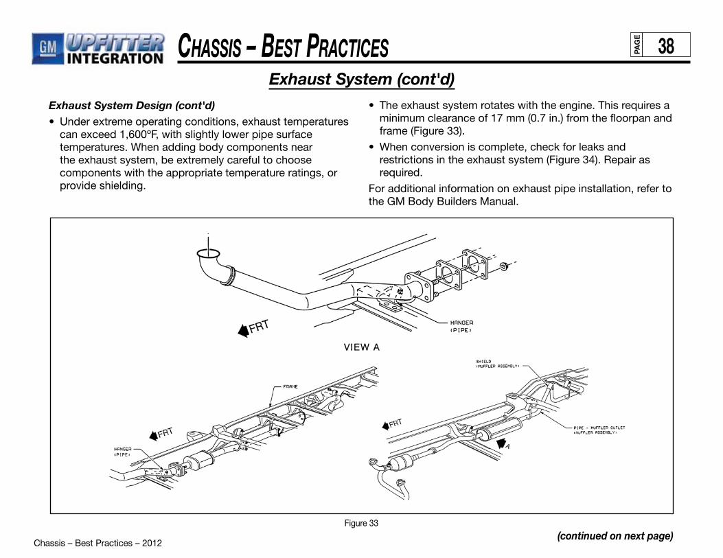
Chassis – Best Practices – 2012
Chassis – Best PraCtiCes 38PAG
E
Exhaust System Design (cont'd)• Under extreme operating conditions, exhaust temperatures
can exceed 1,600ºF, with slightly lower pipe surface temperatures. When adding body components near the exhaust system, be extremely careful to choose components with the appropriate temperature ratings, or provide shielding.
(continued on next page)
Exhaust System (cont'd)• The exhaust system rotates with the engine. This requires a
minimum clearance of 17 mm (0.7 in.) from the floorpan and frame (Figure 33).
• When conversion is complete, check for leaks and restrictions in the exhaust system (Figure 34). Repair as required.
For additional information on exhaust pipe installation, refer to the GM Body Builders Manual.
Figure 33
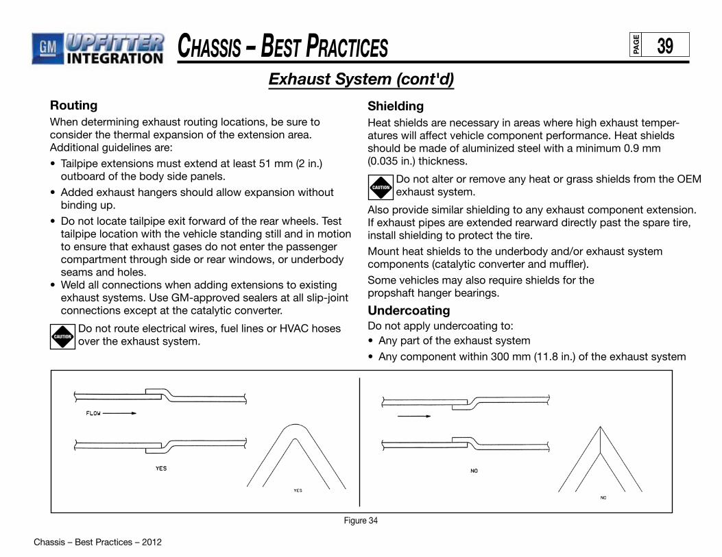
Chassis – Best Practices – 2012
Chassis – Best PraCtiCes 39PAG
E
Exhaust System (cont'd)
RoutingWhen determining exhaust routing locations, be sure to consider the thermal expansion of the extension area. Additional guidelines are:
• Tailpipe extensions must extend at least 51 mm (2 in.) outboard of the body side panels.
• Added exhaust hangers should allow expansion without binding up.
• Do not locate tailpipe exit forward of the rear wheels. Test tailpipe location with the vehicle standing still and in motion to ensure that exhaust gases do not enter the passenger compartment through side or rear windows, or underbody seams and holes.
• Weld all connections when adding extensions to existing exhaust systems. Use GM-approved sealers at all slip-joint connections except at the catalytic converter.
Do not route electrical wires, fuel lines or HVAC hoses over the exhaust system.
ShieldingHeat shields are necessary in areas where high exhaust temper-atures will affect vehicle component performance. Heat shields should be made of aluminized steel with a minimum 0.9 mm (0.035 in.) thickness.
Do not alter or remove any heat or grass shields from the OEM exhaust system.
Also provide similar shielding to any exhaust component extension. If exhaust pipes are extended rearward directly past the spare tire, install shielding to protect the tire.
Mount heat shields to the underbody and/or exhaust system components (catalytic converter and muffler).
Some vehicles may also require shields for thepropshaft hanger bearings.
UndercoatingDo not apply undercoating to:• Any part of the exhaust system
• Any component within 300 mm (11.8 in.) of the exhaust system
CAUTION
CAUTION
Figure 34
Chassis – Best Practices – 2012
Chassis – Best PraCtiCes 40PAG
E
Suspension System
Suspension SystemGeneral RequirementsSVMs should adhere to the following recommendations:
• Do not weld to any axle assembly.
• Design body and equipment arrangements that allow proper load distribution on both front and rear axles.
• Use designs that consider and maintain lateral load equalization.
• Make sure that the unladen vehicle’s center of gravity (after conversion) falls within the limits specified in the FMVSS 105 section of the “Incomplete Vehicle Document”.
• Do not route pipes, wiring or related components in suspension component paths of motion. These components include rear axle, springs, shocks, brake pipes and hoses.
Front Suspension• Since there is a large variation in completed vehicle front
weight due to differences in body weight and equipment, the front suspension alignment must be checked and reset after the vehicle is completed. Caster and camber should be set with reference to the “Z” and “D” trim height dimensions. On C3500 HD trucks with I-beams, camber and caster are designed into the axle/suspension and cannot be adjusted.
• See the Service Manual for complete alignment procedure, specifications and measurement of the “Z” and “D” trim height dimensions under the “Diagnosis and Wheel Alignment” sections.
• C/K Models are designed so that camber and caster do not need adjustment unless severe road impact or accident deformation occurs. Toe should be reset after the vehicle is completed and while at normal operating load with trim height as specified.
Rear SuspensionClearance
• Provide clearance to the body for the suspension, axle, and tires under the following conditions:
— Axle in full jounce against the metal-to-metal stop
— Axle at 4.5-degree roll
— Axle at design position
— Axle in full rebound
• Allow the following clearance for tire chains:
— Design for maximum growth tire.
— Allow 42 mm (1.66 in.) to sides of tire.
— Allow 64 mm (2.5 in.) to top of tire.
— Customer notification may be required in some states if chains cannot be used.
• Refer to the GM Body Builders Manual (C/K section) for additional information on clearance to body/chassis and rear suspension.
• Pipes, wiring, conduits and any other related components must not be placed where they cross the path of motion of the rear axle, driveshaft, axle brake pipes, hoses, spring or tires. Such crossing could result in rupture, wear-through, or separation due to normal axle motion.
Chassis – Best Practices – 2012
Chassis – Best PraCtiCes 41PAG
E
Wheels And TiresSince May, 1971, National Highway Traffic Administration regulations have required manufacturers to maintain specific information on tires. This information is used to notify consumers of defective or non-conforming tires. The SVM should consult with an attorney regarding how these regulations apply.
In compliance with these regulations, General Motors keeps records on tires installed on each vehicle it ships. It is important for the SVM to ship the vehicle with OEM tires. Any tire removed from the vehicle during conversion should be replaced.
The SVM is responsible for keeping records on any tire changes made during conversion. All data must correspond to the correct vehicle identification number (VIN). For specific information, refer to Federal Regulation 574.
All tires must meet FMVSS 120 (CMVSS 120) new tire and rim selection regulations. Factory-installed OEM tires and wheels are designed to operate up to full load capacity when tires are inflated to specification.
Other recommendations are:
• Use only the OEM wheels on any ambulance vehicle.
• The OEM lug nut bearing surface should not retain any wheel trim such as wheel simulators.
• Check wheel lug nuts for proper torque. For torque specifications, see the Owner Guide.
• Check tires and inflate to recommended tire pressure. Refer to either the vehicle’s tire inflation label or the Owner Guide.
For wheel maintenance guidelines, refer to the appropriate GM Service Manual.

Electrical Best Practices – 2012
ElEctrical BEst PracticEs iPAG
E
SCOPE �������������������������������������������������������������������������������������������������������������������������������������������������������������������������������������������������������� A-1
COMMON ELECTRICAL PROBLEMS ����������������������������������������������������������������������������������������������������������������������������������������������������� A-2 General Information �����������������������������������������������������������������������������������������������������������������������������������������������������������������������������A-2 Failure Modes ��������������������������������������������������������������������������������������������������������������������������������������������������������������������������������������A-2 Short Circuit ���������������������������������������������������������������������������������������������������������������������������������������������������������������������������������A-2 Open Circuit ���������������������������������������������������������������������������������������������������������������������������������������������������������������������������������A-2 Intermittent Circuit �����������������������������������������������������������������������������������������������������������������������������������������������������������������������A-3 Sources of Electrical Problems ���������������������������������������������������������������������������������������������������������������������������������������������������A-3
OEM AND AUXILIARY BATTERY GUIDELINES �������������������������������������������������������������������������������������������������������������������������������������� B-1 OEM Battery Guidelines ��������������������������������������������������������������������������������������������������������������������������������������������������������������������� B-1 General Information �������������������������������������������������������������������������������������������������������������������������������������������������������������������� B-1 Discharge Prevention ����������������������������������������������������������������������������������������������������������������������������������������������������������������� B-2 Charging Procedures ������������������������������������������������������������������������������������������������������������������������������������������������������������������ B-3 OEM Battery Relocation Guidelines ��������������������������������������������������������������������������������������������������������������������������������������������������� B-3 Installation ����������������������������������������������������������������������������������������������������������������������������������������������������������������������������������� B-4 Mounting Tray ����������������������������������������������������������������������������������������������������������������������������������������������������������������������������� B-4 Hold-Down ���������������������������������������������������������������������������������������������������������������������������������������������������������������������������������� B-4 Location �������������������������������������������������������������������������������������������������������������������������������������������������������������������������������������� B-5 Vibration �������������������������������������������������������������������������������������������������������������������������������������������������������������������������������������� B-5 Accessibility �������������������������������������������������������������������������������������������������������������������������������������������������������������������������������� B-5 Tilt Angles ����������������������������������������������������������������������������������������������������������������������������������������������������������������������������������� B-5 Temperature �������������������������������������������������������������������������������������������������������������������������������������������������������������������������������� B-5 Auxiliary Battery Guidelines ���������������������������������������������������������������������������������������������������������������������������������������������������������������� B-5 General Information �������������������������������������������������������������������������������������������������������������������������������������������������������������������� B-5 Location �������������������������������������������������������������������������������������������������������������������������������������������������������������������������������������� B-5 Venting ���������������������������������������������������������������������������������������������������������������������������������������������������������������������������������������� B-6 Mounting and Fastening ������������������������������������������������������������������������������������������������������������������������������������������������������������� B-6
Index
(continued on next page)
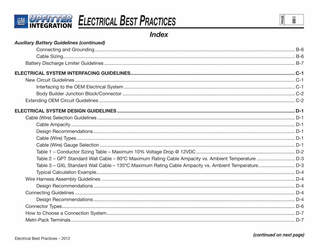
Electrical Best Practices – 2012
ElEctrical BEst PracticEs iiPAG
E
Auxiliary Battery Guidelines (continued) Connecting and Grounding �������������������������������������������������������������������������������������������������������������������������������������������������������� B-6 Cable Sizing �������������������������������������������������������������������������������������������������������������������������������������������������������������������������������� B-6 Battery Discharge Limiter Guidelines ������������������������������������������������������������������������������������������������������������������������������������������������� B-7 ELECTRICAL SYSTEM INTERFACING GUIDELINES ����������������������������������������������������������������������������������������������������������������������������� C-1 New Circuit Guidelines ����������������������������������������������������������������������������������������������������������������������������������������������������������������������� C-1 Interfacing to the OEM Electrical System ���������������������������������������������������������������������������������������������������������������������������������� C-1 Body Builder Junction Block/Connector ����������������������������������������������������������������������������������������������������������������������������������� C-2 Extending OEM Circuit Guidelines ����������������������������������������������������������������������������������������������������������������������������������������������������� C-2
ELECTRICAL SYSTEM DESIGN GUIDELINES ��������������������������������������������������������������������������������������������������������������������������������������� D-1 Cable (Wire) Selection Guidelines ������������������������������������������������������������������������������������������������������������������������������������������������������ D-1 Cable Ampacity �������������������������������������������������������������������������������������������������������������������������������������������������������������������������� D-1 Design Recommendations ��������������������������������������������������������������������������������������������������������������������������������������������������������� D-1 Cable (Wire) Types ���������������������������������������������������������������������������������������������������������������������������������������������������������������������� D-1 Cable (Wire) Gauge Selection ���������������������������������������������������������������������������������������������������������������������������������������������������� D-1 Table 1 – Conductor Sizing Table – Maximum 10% Voltage Drop @ 12VDC ��������������������������������������������������������������������������� D-2 Table 2 – GPT Standard Wall Cable – 80ºC Maximum Rating Cable Ampacity vs� Ambient Temperature ����������������������������� D-3 Table 3 – GXL Standard Wall Cable – 135ºC Maximum Rating Cable Ampacity vs� Ambient Temperature ���������������������������� D-3 Typical Calculation Example ������������������������������������������������������������������������������������������������������������������������������������������������������� D-4 Wire Harness Assembly Guidelines ��������������������������������������������������������������������������������������������������������������������������������������������������� D-4 Design Recommendations ��������������������������������������������������������������������������������������������������������������������������������������������������������� D-4 Connecting Guidelines ����������������������������������������������������������������������������������������������������������������������������������������������������������������������� D-4 Design Recommendations ��������������������������������������������������������������������������������������������������������������������������������������������������������� D-4 Connector Types ��������������������������������������������������������������������������������������������������������������������������������������������������������������������������������� D-6 How to Choose a Connection System ����������������������������������������������������������������������������������������������������������������������������������������������� D-7 Metri-Pack Terminals �������������������������������������������������������������������������������������������������������������������������������������������������������������������������� D-7
Index
(continued on next page)
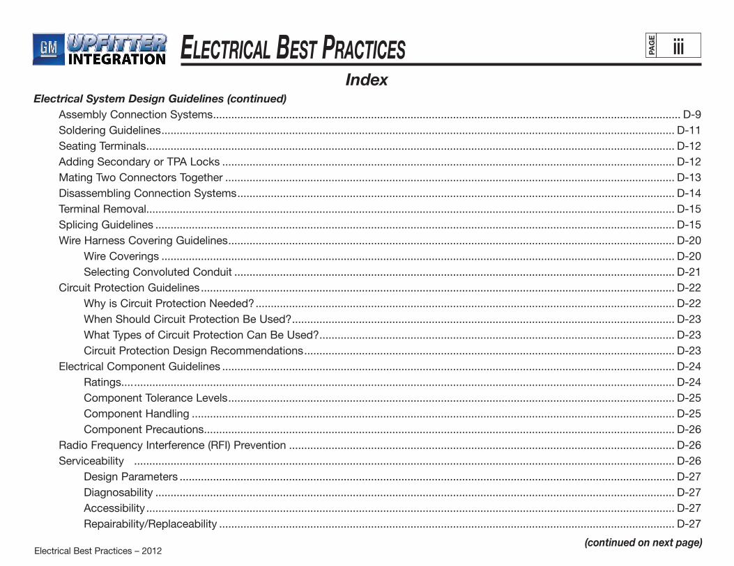
Electrical Best Practices – 2012
ElEctrical BEst PracticEs iiiPAG
E
Electrical System Design Guidelines (continued) Assembly Connection Systems ���������������������������������������������������������������������������������������������������������������������������������������������������������� D-9 Soldering Guidelines ������������������������������������������������������������������������������������������������������������������������������������������������������������������������� D-11 Seating Terminals ������������������������������������������������������������������������������������������������������������������������������������������������������������������������������ D-12 Adding Secondary or TPA Locks ����������������������������������������������������������������������������������������������������������������������������������������������������� D-12 Mating Two Connectors Together ���������������������������������������������������������������������������������������������������������������������������������������������������� D-13 Disassembling Connection Systems ������������������������������������������������������������������������������������������������������������������������������������������������ D-14 Terminal Removal������������������������������������������������������������������������������������������������������������������������������������������������������������������������������ D-15 Splicing Guidelines ��������������������������������������������������������������������������������������������������������������������������������������������������������������������������� D-15 Wire Harness Covering Guidelines ��������������������������������������������������������������������������������������������������������������������������������������������������� D-20 Wire Coverings ������������������������������������������������������������������������������������������������������������������������������������������������������������������������� D-20 Selecting Convoluted Conduit ������������������������������������������������������������������������������������������������������������������������������������������������� D-21 Circuit Protection Guidelines ������������������������������������������������������������������������������������������������������������������������������������������������������������ D-22 Why is Circuit Protection Needed? ������������������������������������������������������������������������������������������������������������������������������������������ D-22 When Should Circuit Protection Be Used? ������������������������������������������������������������������������������������������������������������������������������ D-23 What Types of Circuit Protection Can Be Used? ��������������������������������������������������������������������������������������������������������������������� D-23 Circuit Protection Design Recommendations �������������������������������������������������������������������������������������������������������������������������� D-23 Electrical Component Guidelines ����������������������������������������������������������������������������������������������������������������������������������������������������� D-24 Ratings���� ���������������������������������������������������������������������������������������������������������������������������������������������������������������������������������� D-24 Component Tolerance Levels ��������������������������������������������������������������������������������������������������������������������������������������������������� D-25 Component Handling ��������������������������������������������������������������������������������������������������������������������������������������������������������������� D-25 Component Precautions ����������������������������������������������������������������������������������������������������������������������������������������������������������� D-26 Radio Frequency Interference (RFI) Prevention ������������������������������������������������������������������������������������������������������������������������������� D-26 Serviceability ���������������������������������������������������������������������������������������������������������������������������������������������������������������������������������� D-26 Design Parameters ������������������������������������������������������������������������������������������������������������������������������������������������������������������� D-27 Diagnosability ��������������������������������������������������������������������������������������������������������������������������������������������������������������������������� D-27 Accessibility ������������������������������������������������������������������������������������������������������������������������������������������������������������������������������ D-27 Repairability/Replaceability ������������������������������������������������������������������������������������������������������������������������������������������������������ D-27
Index
(continued on next page)

Electrical Best Practices – 2012
ElEctrical BEst PracticEs ivPAG
E
Electrical System Design Guidelines (continued) Limited-Life Components ��������������������������������������������������������������������������������������������������������������������������������������������������������� D-28 FMVSS/CMVSS Requirements ��������������������������������������������������������������������������������������������������������������������������������������������������������� D-28 FMVSS/CMVSS 108: Lamps, Reflective Devices and Associated Equipment ������������������������������������������������������������������������������� D-28 FMVSS/CMVSS 118: Power-Operated Window Systems ��������������������������������������������������������������������������������������������������������������� D-28 ELECTRICAL SYSTEM INSTALLATION GUIDELINES ��������������������������������������������������������������������������������������������������������������������������� E-1 Wire Handling Guidelines ��������������������������������������������������������������������������������������������������������������������������������������������������������������������E-1 Wire Routing Guidelines ����������������������������������������������������������������������������������������������������������������������������������������������������������������������E-1 Location��������������������������������������������������������������������������������������������������������������������������������������������������������������������������������������� E-1 Tension��������������� ��������������������������������������������������������������������������������������������������������������������������������������������������������������������������E-2 Accessibility ���������������������������������������������������������������������������������������������������������������������������������������������������������������������������������E-2 Appearance ���������������������������������������������������������������������������������������������������������������������������������������������������������������������������������E-2 Wire Fastening Guidelines �������������������������������������������������������������������������������������������������������������������������������������������������������������������E-3 Wire and Electrical Component Protection Guidelines �����������������������������������������������������������������������������������������������������������������������E-3 Protective Devices �����������������������������������������������������������������������������������������������������������������������������������������������������������������������E-3 Grounding Guidelines ��������������������������������������������������������������������������������������������������������������������������������������������������������������������������E-4 CUSTOMER CONVENIENCE ���������������������������������������������������������������������������������������������������������������������������������������������������������������������F-1 OEM Component Location Guidelines ������������������������������������������������������������������������������������������������������������������������������������������������F-1 Customer Convenience �����������������������������������������������������������������������������������������������������������������������������������������������������������������������F-1 Function Marking �������������������������������������������������������������������������������������������������������������������������������������������������������������������������������F-1 Location Identification �������������������������������������������������������������������������������������������������������������������������������������������������������������������������F-1 Instructions ������������������������������������������������������������������������������������������������������������������������������������������������������������������������������������������F-1 Documentation ������������������������������������������������������������������������������������������������������������������������������������������������������������������������������������F-1
Index
(continued on next page)
Electrical Best Practices – 2012
ElEctrical BEst PracticEs vPAG
E
HEADLAMP/FOG LAMP GUIDELINES ����������������������������������������������������������������������������������������������������������������������������������������������������G-1 Headlamp Aiming ������������������������������������������������������������������������������������������������������������������������������������������������������������������������������� G-1 ELECTRICAL SYSTEM PRECAUTIONS �������������������������������������������������������������������������������������������������������������������������������������������������� H-1 Air Bag (SIR) Precautions ������������������������������������������������������������������������������������������������������������������������������������������������������������������� H-1 SIR Identification Views ���������������������������������������������������������������������������������������������������������������������������������������������������������������������� H-2 General Service Instructions ��������������������������������������������������������������������������������������������������������������������������������������������������������������� H-3 Disabling and Enabling the Air Bag System ������������������������������������������������������������������������������������������������������������������������������H-3 Welding Precautions ������������������������������������������������������������������������������������������������������������������������������������������������������������������� H-4 High Voltage Precautions ����������������������������������������������������������������������������������������������������������������������������������������������������������� H-4 APPENDIX I �����������������������������������������������������������������������������������������������������������������������������������������������������������������������������������������������J-1 Glossary of Terms and Definitions �������������������������������������������������������������������������������������������������������������������������������������������������������J-1 APPENDIX II ���������������������������������������������������������������������������������������������������������������������������������������������������������������������������������������������� K-1
Index
Connecting Terminology ��������������������������������������������������������������������������������������������������������������������������������������������������������������������� K-1 Unsealed Connection Systems ���������������������������������������������������������������������������������������������������������������������������������������������������������� K-3 Sealed Connection Systems �������������������������������������������������������������������������������������������������������������������������������������������������������������� K-9
FUSES ������������������������������������������������������������������������������������������������������������������������������������������������������������������������������������������������������ K-13 Electric Fuses ���������������������������������������������������������������������������������������������������������������������������������������������������������������������������������� K-13 Fuse Characteristics ������������������������������������������������������������������������������������������������������������������������������������������������������������������������� K-13 ATO Fuse Components �������������������������������������������������������������������������������������������������������������������������������������������������������������������� K-14 Maxi Fuse Components ������������������������������������������������������������������������������������������������������������������������������������������������������������������� K-17 Available Tools ���������������������������������������������������������������������������������������������������������������������������������������������������������������������������������� K-18

Electrical Best Practices - 2012
ElEctrical BEst PracticEs A-1PAG
E
Scope
The scope of this Electrical Manual is to define General Motors recommendations for the design and installation of non-OEM (Original Equipment Manufacturer) low-voltage electrical systems and components in GM vehicles by personnel engaged in the conversion of automotive vehicles. Also included in this manual are guidelines for the interfacing of Upfitter installed electrical systems to the General Motors OEM electrical system. This is not a “how to” manual. It assumes the reader has technical expertise in the area. Ultimate responsibility for all work rests with the Upfitters.
Electrical Best Practices - 2012
ElEctrical BEst PracticEs A-2PAG
E
Common Electrical Problems – General Information
GENERAL INFORMATION
This section describes several common automotive electrical problems and failure modes. General Motors recommends that Upfitters become familiar with these common problems. Doing so will help to avoid potential failure and other serious problems in the vehicle’s electrical system and components.
FAILURE MODES
Short Circuit
A short circuit is a connection of comparatively low resistance, made either accidentally or intentionally, between two points in an electrical circuit. In other words, a short circuit is a direct connection between two circuits. Typically, when a power circuit shorts to a grounded circuit or conductive metal in the vehicle, it causes a circuit protection device (CPD) to open and protect the wiring from damage. However, it is possible for a short circuit to cause damage to the wiring and to the vehicle. This occurs if a circuit is not properly protected. The tremendous amount of current that flows through a wire, generated by a short, causes the wire to heat up, melt the insulation around the wire and adjacent wires, and may even lead to a thermal event. Damage to a vehicle resulting from a short circuit can be avoided with proper fusing. Therefore, it is very important to follow good circuit protection guidelines any time a new circuit is added to a vehicle electrical system. A short circuit may result when a cut, pinched or chafed wire makes contact with a grounded component of the vehicle.
Open Circuit
An open circuit is a circuit that has lost contact in a way that prohibits the flow of current. This condition creates infinite resistance between two circuits and usually results in the malfunctioning of an electrical component. An open circuit may result from: •Apinchedorcutwire •Improperlyseatedterminal(s)inaconnector •Apoororimproperterminalcrimp •Corrodedterminal(s) •Improperlyconnectedringterminal
(continued on next page)
Electrical Best Practices - 2012
ElEctrical BEst PracticEs A-3PAG
E
Intermittent Circuit
An intermittent circuit is a circuit that repeatedly opens or shorts temporarily. In other words, the circuit makes and breaks contact over and over again. It may be caused by: •Apinchedwire •Alooseringterminal •Improperseatingofterminal(s)inaconnector •Incompletematingofconnectors •Corrodedterminals
Sources of Electrical Problems
A variety of conditions can cause problems with the automotive electrical system and its components. These include: •Cut,broken,pinchedorchafedwire •Burnedwiringormeltedinsulation •Looseorunconnectedringterminal •Terminalcoregripwingscrimpedoverwireinsulation •Uncrimpedterminalcoregripwings •Terminalbackedoutofconnector •Bentordamagedterminalinconnector •Corrodedterminal •Partiallyorcompletelydisconnectedconnector •Poorormissingground •Crossedwireinconnector •Missingwire •Misroutedwire •Shortwirelead(s) •Damagedconnector •Improperlyinstalledlightbulb •Disconnectedlightbulbsocket
Common Electrical Problems – General Information (cont'd)
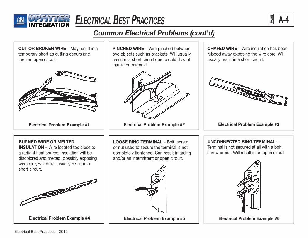
Electrical Best Practices - 2012
ElEctrical BEst PracticEs A-4PAG
E
Common Electrical Problems (cont'd)
CUT OR BROKEN WIRE – May result in atemporary short as cutting occurs and then an open circuit.
Electrical Problem Example #1 Electrical Problem Example #2 Electrical Problem Example #3
Electrical Problem Example #4 Electrical Problem Example #5 Electrical Problem Example #6
PINCHED WIRE – Wire pinched between two objects such as brackets. Will usually result in a short circuit due to cold flow of insulation material
CHAFED WIRE – Wire insulation has beenrubbed away exposing the wire core. Willusually result in a short circuit.
BURNED WIRE OR MELTED INSULATION – Wire located too close to a radiant heat source. Insulation will be discolored and melted, possibly exposing wire core, which will usually result in a short circuit.
LOOSE RING TERMINAL – Bolt, screw, or nut used to secure the terminal is not completely tightened. Can result in arcing and/or an intermittent or open circuit.
UNCONNECTED RING TERMINAL – Terminal is not secured at all with a bolt, screw or nut. Will result in an open circuit.

Electrical Best Practices - 2012
ElEctrical BEst PracticEs A-5PAG
E
Common Electrical Problems (cont'd)
TERMINAL CORE GRIP WINGS CRIMPED OVER WIRE INSULATION – Terminal has no contact with the wire core due to insulation not being properly removed or positioned. Results in an open circuit.
Electrical Problem Example #7
TERMINAL CORE GRIP WINGS NOTCRIMPED – Terminal has not been secured to the wire core resulting in an intermittent or open circuit.
Electrical Problem Example #8 Electrical Problem Example #9
Electrical Problem Example #11Electrical Problem Example #10 Electrical Problem Example #12
TERMINAL BACKED OUT OF CONNECTOR – Terminal has not stayed properly positioned inside the connector. As it “backs out” an intermittent or open circuit may result.
BENT OR DAMAGED TERMINAL INCONNECTOR – May result in an intermittent or open circuit. A short circuit may occur if the bending causes two terminals to touch.
CORRODED TERMINAL – Corroding is evident when a greenish-white powder appears on the terminal. May result in high temperature in the connector or an open circuit due to high resistance.
CONNECTOR PARTIALLY CONNECTED –“Partially” indicates that some terminals in a connector are making contact while others are intermittent or open circuit across the connection.

Electrical Best Practices - 2012
ElEctrical BEst PracticEs A-6PAG
E
Common Electrical Problems (cont'd)
Electrical Problem Example #13 Electrical Problem Example #14 Electrical Problem Example #15
Electrical Problem Example #17Electrical Problem Example #16 Electrical Problem Example #18
CONNECTOR COMPLETELYDISCONNECTED – The connector is not mated at all and all terminals are open circuit across the connection.
POOR OR MISSING GROUND – Groundterminal not fastened or only partially fastened to the body sheet metal. Can result in an intermittent or open circuit.
CROSSED WIRE IN CONNECTOR – Wire has been inserted into the wrong cavity in the connector during initial assembly or previous repair. May result in a malfunction of the circuit which could lead to a short circuit.
MISSING WIRE – May have been omittedduring initial manufacturing of the harnessassembly or left out during vehicle build.
MIS-ROUTED WIRE – Wire has been positioned incorrectly during vehicle build. Will usually result in one or more of the listed example problems occurring.
SHORT WIRE LEAD(S) – Wire may have been assembled improperly by harness manufacturer or might have been misrouted during assembly.
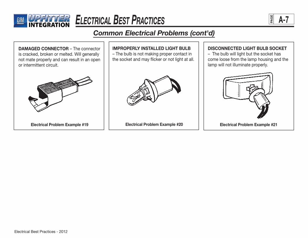
Electrical Best Practices - 2012
ElEctrical BEst PracticEs A-7PAG
E
Common Electrical Problems (cont'd)
DAMAGED CONNECTOR – The connector is cracked, broken or melted. Will generally not mate properly and can result in an open or intermittent circuit.
IMPROPERLY INSTALLED LIGHT BULB – The bulb is not making proper contact in the socket and may flicker or not light at all.
DISCONNECTED LIGHT BULB SOCKET – The bulb will light but the socket has come loose from the lamp housing and the lamp will not illuminate properly.
Electrical Problem Example #20Electrical Problem Example #19 Electrical Problem Example #21
Electrical Best Practices - 2012
ElEctrical BEst PracticEs B-1PAG
E
OEM and Auxiliary Battery Guidelines
OEM BATTERY GUIDELINES
The information in this section will help the Upfitter to prevent OEM battery discharge when upfitting GM vehicles. It is the Upfitter’s responsibility to make sure that the OEM battery is at the same or higher state of charge when the completed vehicle is shipped, than what it was when the vehicle was received.
Additionally, integration of Upfitter equipment with the vehicle electrical system should be done with the aim of protecting the battery from excessive discharge with the ignition off.
General Information
GeneralMotorsLightandMediumDutyTrucksareequippedwithmaintenance-free, sealed batteries that are designed to perform three major functions: •Provideasourceofelectricalenergyforcrankingtheengine •Actasavoltagestabilizerforthevehicleelectricalsystem •Provideaddedenergywhenthevehicle’selectricalload
requirements exceed the output of the generator.
When connecting directly to the OEM battery, use only OEM-approved connecting devices. Contact the Upfitter Integration group for approved components.
Upfitter provided battery bolts, that incorporate a threaded stud for direct attachment to the battery, should comply with OEM requirements for configuration, length, material, and terminal interface requirements. Failure to do so could compromise the vehicle electrical system performance, reduce battery life and physically damage the battery.
Battery bolts should be torqued to 17.0 ± 3.0 Nm. Do not over-torque as this could damage the battery.
Terminal attaching nuts, that are installed on Upfitter battery bolt/studs, should always be torqued to a specification that is lower than the installation torque requirement for the battery bolt itself, to prevent battery bolt over-torquing.
Someelectricaldevicesmayimposea“parasitic”loadontheOEMbattery. Upfitters should not install this type of device in a GM vehicle.
Whenever practical and customer convenient, wire non-OEM electrical devices so that they are controlled by the vehicle’s ignition system. This will prevent battery discharge if the electrical device is inadvertently left on. (Note:Seethe“InterfacingtotheOEMElectricalSystem”sectionforrecommendedconnectionmethodstotheOEMignition circuit.) Upfitter electrical devices that have a parasitic current draw should not be added to the vehicle.
Refer to the appropriate GM service manual for specific information on battery usage, diagnosis and on-vehicle service procedures.
(continued on next page)
CAUTION
CAUTION
CAUTION
Electrical Best Practices - 2012
ElEctrical BEst PracticEs B-2PAG
E
Discharge Prevention
General Motors recommends that Upfitters implement practices that will prevent battery discharge that otherwise may occur during the conversion process. •Whenstoringavehicleformorethan10days(eitherbeforeorafter
the conversion process), disconnect all negative battery terminals. Someelectronicdevices,suchastheradio,enginecontrolmodule(ECM), powertrain control module (PCM), and the vehicle control module (VCM), impose small, continuous current drains on the battery. These are commonly called parasitic loads. If the vehicle is stored for an extended period of time, parasitic loads can deeply discharge the battery. Allowing it to stand in a deeply discharged state for long periods of time can permanently damage the battery.
Dischargedbatteriescanfreezeattemperaturesashighas20degrees Fahrenheit, causing permanent damage. Never charge a frozenbattery.
•Periodically(every30-45days)rechargethebatteryofanyvehiclethat has been stored for 30 days or more. The negative (ground) cable should be disconnected after each recharging.
•Alwaysturntheignitionoffbeforeconnectingordisconnectingbattery cables. Failure to do so may damage the ECM, PCM, VCM, radio or other electronic components.
•Donotstarttheenginetomovethevehiclefromoneassemblystation to another within the same building. This discharges the battery and can foul the spark plugs. GM recommends moving the vehicle by some other method, such as pushing by hand.
•Neverleavethevehicleignitionswitchinthe“ON”positioniftheengine is not running.
•Donotplaythevehicle’sradio,TV,DVDplayerorotherelectricalequipment during the conversion process unless required for proper vehicle processing (e.g., testing the operation of such components).
•Donotleavevehiclehoodanddoorsopenduringnon-workperiods(over night, work breaks, shift changes, extended downtimes, etc.) if underhood or interior lights have not been disconnected. All electrical current-drawing devices should also be turned off during these periods.
•Somevehiclesareequippedwithaninteriorlightoverrideswitchlocated on the instrument panel. Keep this switch in the “OFF” position and switch to the “ON” or “DOOR” position only as needed toenergizetheinteriorlightcircuitforcheckingpurposes.(Note: Keeping this switch in the “OFF” position nullifies the need for keeping the vehicle doors closed.)
•AllUpfitter-addedelectricaldevicesshouldbeinstalledinthe“OFF” position and all Upfitter electrical checks performed during the assembly operation should require that the device be left in the “OFF” position. Upfitters may find it more practical to disconnect the negative battery terminal than to implement the protective practices outlined above. If choosing this method, the battery should remain disconnected throughout the conversion process. It should be reconnected only to check the function of the Upfitter-added electrical system or to move the vehicle between buildings or to a storage lot.
Battery cable terminal attaching bolts, that are disconnected by an Upfitter, must be torqued to 17.0 ± 3.0 Nm when reinstalled.Do not over-torque.
Always reconnect the positive battery cable first, if both the positive and negative cables have been disconnected. This will reduce the potential for accidentally short-circuiting the battery to ground.
Care should be exercised when removing and/or reinstalling battery terminal attaching bolts. Inadvertent grounding of the positive terminal can result in severe arcing that could cause injury to the operator.
(continued on next page)
CAUTION
CAUTION
CAUTION
OEM and Auxiliary Battery Guidelines (cont'd)

Electrical Best Practices - 2012
ElEctrical BEst PracticEs B-3PAG
E
Charging Procedures
If it is necessary to jump-start a vehicle or recharge an OEM battery, make sure that all charger/cable connections are clean and tight. RefertotheappropriateGMServiceManualand/orOwner’sManualfor jump starting procedures. The proper charging procedure follows: 1. Connect the positive lead from the charging device to the
positive terminal of the battery.
2. Attach the negative lead from the charging device to a grounded metal vehicle component, away from the battery.
Do not attach the negative lead to the braking system’s master cylinder or to any electrical/electronic component housing.DoingsocancausedamagetotheAnti-LockBrakeSystem(ABS)moduleorinternalcomponentsoftheelectrical/electronic device.
3. Selectthechargersettingthatwillrenderthehighestchargeratefor12-voltbatteries.Setadjustablechargersat16volts.
4. Fullychargethebattery.
Batteries should be checked every hour while on charge. Discontinuechargingifthebatterybecomeshot(125°F),gasses violently or spews electrolyte through the vents.
To avoid a potential explosion, perform this procedure only in a well-ventilated area, away from any flame- or spark-producing source. Failure to do so may cause serious bodily injury.
Always turn the ignition switch to the “OFF” position when connecting or disconnecting the battery charger or jumper cables. Failure to do so can damage the ECM, PCM, VCM, radio or other electronic components.
Neverchargeafrozenbattery.
(continued on next page)
OEM and Auxiliary Battery Guidelines (cont'd)
CAUTION
CAUTION
OEM BATTERY RELOCATION GUIDELINESThe following guidelines apply to commercial vehicle conversions. General Motors does not recommend relocating the OEMbattery in vans, pickup trucks, or sport-utility vehicles.
The following guidelines apply to commercial vehicle conversions. General Motors does not recommend relocating the OEM battery in vans, pickup trucks, or sport-utility vehicles. If it is necessary to relocate the OEM battery, place and position it so that it can make use of the existing battery cables. If this is not possible and longer cables are required, use wire of a proportionately larger gauge.
If relocating the battery requires attaching the negative ground cabletoaframerail,acableofequalorgreatergaugesizemustbeprovided between the frame rail and the vehicle engine block. This is necessary because of the heavy electrical loads imposed by the starting circuit.
To ensure proper electrical system operation, refer to the table in Figure 1 to determine the correct battery cable to use.
Figure 1
Combined Length of Positive and Negative Cables
Cable Guide Maximum Cable Length in Inches (Copper Core)
4 66
2 107
0 170
CAUTION
CAUTION
CAUTION
Electrical Best Practices - 2012
ElEctrical BEst PracticEs B-4PAG
E
(continued on next page)
OEM and Auxiliary Battery Guidelines (cont'd)
Installation
When installing batteries and cables, the body upfitter should observe the following guidelines. Noncompliance may result in vehicle electrical system failure, engine shutdown, loss of backup brake system or the possibility of a thermal event.
• Avoidroutingcablesinareaswheretheywillcontactsharpmetal edges, either in their normal positions or during maintenance.
• Donotbendcablesinaradiussmallerthantentimesthecablediameter. Doing so may cause insulation failure.
• SupportUpfitter-installedbatterycableswithclipsspacednotmorethan250mmapart.Thispreventsthecablesfrommoving freely and rubbing against any fixed or movable vehicle component.
• Userubber-lined(notrubber-dipped)cableretainingclips.
• Cablesshouldnotbespliced.Cablemodificationscancausevehicle starting problems and the loss of other key electrical systems.
• Clipcablestothebatterytrayinamannerthatpreventscablepull loads from transferring directly to the battery posts. Failure to do so can result in loose terminals, poor starting or battery failure. Added strain to posts can cause battery acid to leak.
• Cableattachmentstothebatteryterminalshouldnotplaceundue strain on the connection.
— Cables adjacent to the connections should have no sharp bends.
—Routecablesdownward,ratherthanhorizontally,fromthe terminals to prevent lever action which may loosen connections.
• Donotapplyterminalcorrosioninhibitorsorothercoatingstosealed electrical contact areas.
• Torquebatteryterminalsto17.0±3.0Nm.Donotover-torque.
Mounting Tray
The battery mounting tray should be made of a substantial material (minimum1.75mmthick)orsufficientlyreinforcedtoresistflexingandcracking. General Motors also recommends the following:
• Thetrayshouldprovidefirm,continuoussupporttothebatteryto prevent amplifying vibration levels.
• Thetrayormountingsshouldhavenoprotrusionsorprojectionsthat would damage the battery.
• Topreventelectrolytespillageorleadfatigue,avoidcantileveredmountings and mount the tray flatly.
• Aroundedlipofadequateheightshouldbeprovidedaroundtheperimeter of the tray to ensure stiffness and retention.
It is important to mount the battery in such a way to ensure it is capable of withstanding a static force applied to any of its four corners.
Hold-Down
The battery hold-down should be able to withstand shock loading and prevent any battery movement relative to the mounting base or holddown. Torque requirements for a hold-down should comply with accepted industry standards. General Motors recommends a bottom hold-down, centrally located at the sides of the battery.
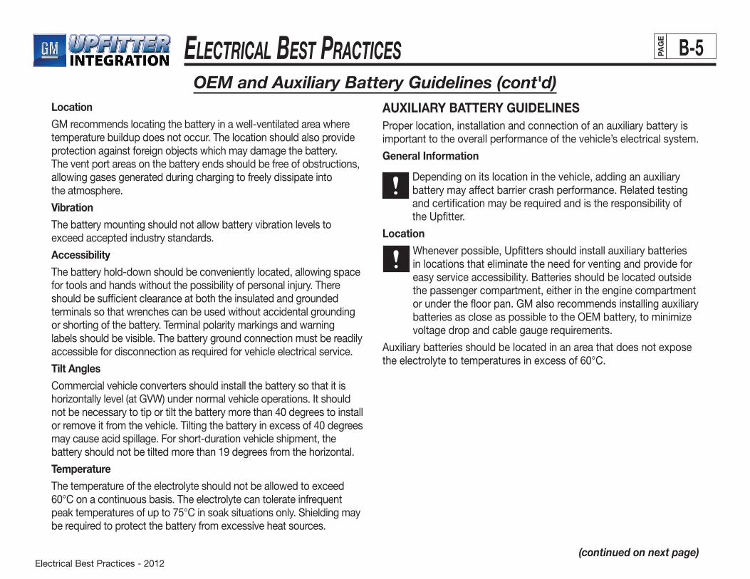
Electrical Best Practices - 2012
ElEctrical BEst PracticEs B-5PAG
E
OEM and Auxiliary Battery Guidelines (cont'd)AUXILIARY BATTERY GUIDELINESProper location, installation and connection of an auxiliary battery is important to the overall performance of the vehicle’s electrical system.
General Information
Depending on its location in the vehicle, adding an auxiliary battery may affect barrier crash performance. Related testing and certification may be required and is the responsibility of the Upfitter.
Location
Whenever possible, Upfitters should install auxiliary batteries in locations that eliminate the need for venting and provide for easy service accessibility. Batteries should be located outside the passenger compartment, either in the engine compartment or under the floor pan. GM also recommends installing auxiliary batteriesascloseaspossibletotheOEMbattery,tominimizevoltage drop and cable gauge requirements.
Auxiliary batteries should be located in an area that does not expose theelectrolytetotemperaturesinexcessof60°C.
(continued on next page)
Location
GM recommends locating the battery in a well-ventilated area where temperature buildup does not occur. The location should also provide protection against foreign objects which may damage the battery. The vent port areas on the battery ends should be free of obstructions, allowing gases generated during charging to freely dissipate into the atmosphere.
Vibration
The battery mounting should not allow battery vibration levels to exceed accepted industry standards.
Accessibility
The battery hold-down should be conveniently located, allowing space for tools and hands without the possibility of personal injury. There should be sufficient clearance at both the insulated and grounded terminals so that wrenches can be used without accidental grounding or shorting of the battery. Terminal polarity markings and warning labels should be visible. The battery ground connection must be readily accessible for disconnection as required for vehicle electrical service.
Tilt Angles
Commercial vehicle converters should install the battery so that it is horizontallylevel(atGVW)undernormalvehicleoperations.Itshouldnotbenecessarytotiportiltthebatterymorethan40degreestoinstallorremoveitfromthevehicle.Tiltingthebatteryinexcessof40degreesmay cause acid spillage. For short-duration vehicle shipment, the batteryshouldnotbetiltedmorethan19degreesfromthehorizontal.
Temperature
The temperature of the electrolyte should not be allowed to exceed 60°Conacontinuousbasis.Theelectrolytecantolerateinfrequentpeaktemperaturesofupto75°Cinsoaksituationsonly.Shieldingmaybe required to protect the battery from excessive heat sources.
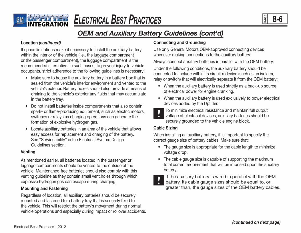
Electrical Best Practices - 2012
ElEctrical BEst PracticEs B-6PAG
E
Location (continued)
If space limitations make it necessary to install the auxiliary battery within the interior of the vehicle (i.e., the luggage compartment or the passenger compartment), the luggage compartment is the recommended alternative. In such cases, to prevent injury to vehicle occupants, strict adherence to the following guidelines is necessary:
• Makesuretohousetheauxiliarybatteryinabatteryboxthatissealed from the vehicle’s interior environment and vented to the vehicle’s exterior. Battery boxes should also provide a means of draining to the vehicle’s exterior any fluids that may accumulate in the battery tray.
• Donotinstallbatteriesinsidecompartmentsthatalsocontainspark- or flame-producing equipment, such as electric motors, switches or relays as charging operations can generate the formation of explosive hydrogen gas.
• Locateauxiliarybatteriesinanareaofthevehiclethatallowseasy access for replacement and charging of the battery. See“Serviceability”intheElectricalSystemDesign Guidelines section.
Venting
As mentioned earlier, all batteries located in the passenger or luggage compartments should be vented to the outside of the vehicle. Maintenance-free batteries should also comply with this venting guideline as they contain small vent holes through which explosive hydrogen gas can escape during charging.
Mounting and Fastening
Regardless of location, all auxiliary batteries should be securely mounted and fastened to a battery tray that is securely fixed to the vehicle. This will restrict the battery’s movement during normal vehicle operations and especially during impact or rollover accidents.
OEM and Auxiliary Battery Guidelines (cont'd)Connecting and Grounding
Use only General Motors OEM-approved connecting devices whenever making connections to the auxiliary battery.
Always connect auxiliary batteries in parallel with the OEM battery.
Under the following conditions, the auxiliary battery should be connected to include within its circuit a device (such as an isolator, relay or switch) that will electrically separate it from the OEM battery:
• Whentheauxiliarybatteryisusedstrictlyasaback-upsourceof electrical power for engine cranking.
• Whentheauxiliarybatteryisusedexclusivelytopowerelectricaldevices added by the Upfitter.
Tominimizeelectricalresistanceandmaintainfulloutputvoltage at electrical devices, auxiliary batteries should be securely grounded to the vehicle engine block.
Cable Sizing
When installing an auxiliary battery, it is important to specify the correctgaugesizeofbatterycables.Makesurethat:
• Thegaugesizeisappropriateforthecablelengthtominimizevoltage drop.
• Thecablegaugesizeiscapableofsupportingthemaximumtotal current requirement that will be imposed upon the auxiliary battery.
If the auxiliary battery is wired in parallel with the OEM battery,itscablegaugesizesshouldbeequalto,orgreaterthan,thegaugesizesoftheOEMbatterycables.
(continued on next page)

Electrical Best Practices - 2012
ElEctrical BEst PracticEs B-7PAG
E
The table in Figure 2 provides information that can help to select the correctcablegaugesize.
OEM and Auxiliary Battery Guidelines (cont'd)
BATTERY CABLE SAE J1127 CONVERSION/CONSTRUCTION TABLE
MetricSize
EnglishGauge
MetricConstruction*
MetricArea
13mm2 6ga. 37/.66 12.658mm2
19 4 61/.63 19.015
32 2 127/.57 32.407
32 2 7x19/.57 33.938
40 1 127/.63 39.589
40 1 7x19/.63 41.459
50 0 127/.71 50.282
50 0 7x19/.71 52.657
62 2/0 127/.79 62.251
62 2/0 7x19/.79 65.192
81 3/0 7x37/.63 80.737
103 4/0 7x37/.71 102.543
*No.ofStrands/StrandDiameterinmm
Figure 2
• Donotrequirethatbatterycable(s)becut.
• BedesignedtoacceptunmodifiedOEMbatterycableterminals.
• IncorporateOEM-typebatteryterminalsfortheattachmenttotheOEM battery.
• AttachtothebatterywithGM-approvedbolts.
• Bedesignedsothatifattacheddirectlytothebattery,thelimiter electrical interface connection be compatible with the battery terminal (post) mating surface (i.e., will make full surface terminal-to-terminal contact). This will allow a solid and tight battery interface connection to be made which will ensure that the vehicle’s electrical system is not degraded. The bolt used to attach the limiter to the battery post must be the correct length and should conform to OEM configuration, material and terminal interface requirements. Care must be exercised not to over-torque this bolt (see “OEM Battery Guidelines,” General Information — this manual section).
This section contains guidelines and recommendations to assist the Upfitter when interfacing electrical connections to the host OEM wiring system. Improper electrical connections can result in failures of both the Upfitter and OEM electrical systems.
To the maximum degree possible, Upfitter electrical systems should be functionally separated from the OEM electrical system. This will help to prevent potential failures and/or damage to the OEM electrical system in the event there is an Upfitter electrical system failure.BATTERY DISCHARGE LIMITER GUIDELINES
The design and installation of battery discharge limiting devices, that are installed in GM vehicles by Upfitters, should comply with the following recommendations:
• Bedesignedtoconformtoallapplicablerecommendationsoutlined in the “Electrical Component Guidelines” sub-section of theElectricalSystemDesignGuidelinessectionofthismanual.
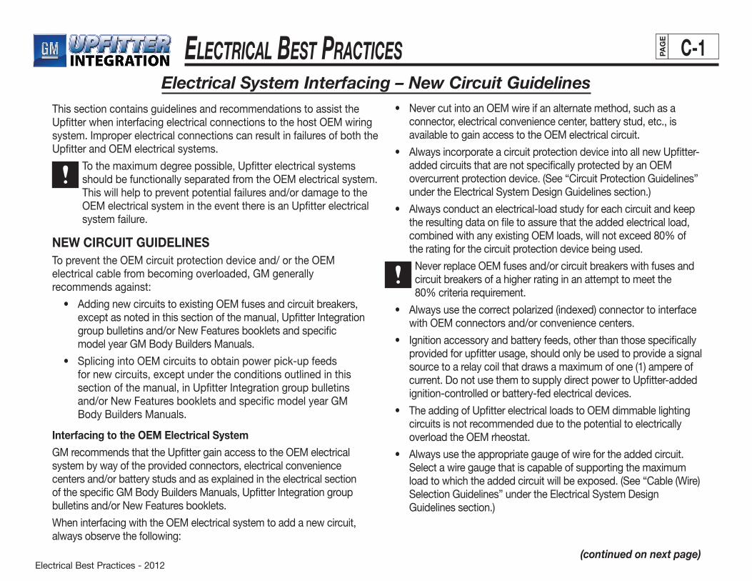
ElEctrical BEst PracticEs
Electrical Best Practices - 2012
C-1PAG
E
NEW CIRCUIT GUIDELINESTo prevent the OEM circuit protection device and/ or the OEM electrical cable from becoming overloaded, GM generally recommends against:
• AddingnewcircuitstoexistingOEMfusesandcircuitbreakers,except as noted in this section of the manual, Upfitter Integration group bulletins and/or New Features booklets and specific model year GM Body Builders Manuals.
• SplicingintoOEMcircuitstoobtainpowerpick-upfeedsfor new circuits, except under the conditions outlined in this section of the manual, in Upfitter Integration group bulletins and/or New Features booklets and specific model year GM Body Builders Manuals.
Interfacing to the OEM Electrical System
GM recommends that the Upfitter gain access to the OEM electrical system by way of the provided connectors, electrical convenience centers and/or battery studs and as explained in the electrical section of the specific GM Body Builders Manuals, Upfitter Integration group bulletins and/or New Features booklets.
When interfacing with the OEM electrical system to add a new circuit, always observe the following:
Electrical System Interfacing – New Circuit Guidelines
(continued on next page)
This section contains guidelines and recommendations to assist the Upfitter when interfacing electrical connections to the host OEM wiring system. Improper electrical connections can result in failures of both the Upfitter and OEM electrical systems.
To the maximum degree possible, Upfitter electrical systems should be functionally separated from the OEM electrical system. This will help to prevent potential failures and/or damage to the OEM electrical system in the event there is an Upfitter electrical system failure.
• NevercutintoanOEMwireifanalternatemethod,suchasaconnector, electrical convenience center, battery stud, etc., is available to gain access to the OEM electrical circuit.
• AlwaysincorporateacircuitprotectiondeviceintoallnewUpfitter-added circuits that are not specifically protected by an OEM overcurrentprotectiondevice.(See“CircuitProtectionGuidelines”undertheElectricalSystemDesignGuidelinessection.)
• Alwaysconductanelectrical-loadstudyforeachcircuitandkeepthe resulting data on file to assure that the added electrical load, combinedwithanyexistingOEMloads,willnotexceed80%of the rating for the circuit protection device being used.
Never replace OEM fuses and/or circuit breakers with fuses and circuit breakers of a higher rating in an attempt to meet the 80%criteriarequirement.
• Alwaysusethecorrectpolarized(indexed)connectortointerfacewith OEM connectors and/or convenience centers.
• Ignitionaccessoryandbatteryfeeds,otherthanthosespecificallyprovided for upfitter usage, should only be used to provide a signal source to a relay coil that draws a maximum of one (1) ampere of current. Do not use them to supply direct power to Upfitter-added ignition-controlled or battery-fed electrical devices.
• TheaddingofUpfitterelectricalloadstoOEMdimmablelightingcircuits is not recommended due to the potential to electrically overload the OEM rheostat.
• Alwaysusetheappropriategaugeofwirefortheaddedcircuit. Selectawiregaugethatiscapableofsupportingthemaximumloadtowhichtheaddedcircuitwillbeexposed.(See“Cable(Wire)SelectionGuidelines”undertheElectricalSystemDesign Guidelines section.)

ElEctrical BEst PracticEs
Electrical Best Practices - 2012
C-2PAG
E
Body Builder Junction Block/Connector
When provided by the OEM, the body builder junction block/ connector is powered by direct battery- and ignition-controlled circuits. It should be used to power all Upfitter-added circuits that do not require the interfacing to an OEM control device. Circuit protectionshouldbeaddedwithin18inchesofthewire’slengthfrom the OEM junction block/connector.
Electrical System Interfacing – Extending OEM Circuit Guidelines
EXTENDING OEM CIRCUIT GUIDELINESIf a connector is provided for Upfitter interfacing, use the mating OEM connector to extend the OEM circuit. Examples of OEM circuits with an interfacing connector are interior lighting and rear speaker circuits.
Splicingislessreliablethanotherconnectingmethodsandisgenerally not recommended except in cases where the OEM circuit does not have an interfacing connector. In such cases, splicing is acceptable, providing it complies with the recommendations outlinedinthe“SplicingGuidelines”subheadintheElectricalSystemDesignGuidelinessectionofthismanual.Examplesofcircuits which do not always provide interfacing connectors are power door lock, front fog lamp and exterior running lamp circuits.
Caution must be exercised whenever an existing OEM circuit isutilizedasthepowersourceforanUpfitter-addedcircuit.The Upfitter should always incorporate a relay into the system whenever the added load demands a higher current than that which the host OEM wiring or circuit protection device can provide. The OEM wiring can act as a signal source for the relay coil. The relay then channels power from the vehicle battery power-pickup point to the added circuit. The power supply wire extending from the battery power-pickup point shouldbeofthepropersizeandprotectedbyanappropriatefuseorcircuitbreaker.(See“Cable(Wire)SelectionGuidelines” and “Circuit Protection Guidelines” headings of this Manual.)
When adding electrical loads to existing OEM circuits, Upfitters should conduct an electrical load study, document its data and keep it on file. Doing so will assure that the OEM wire gauge and circuit protection device is adequate to support the added load. The total circuit current draw (combined Upfitter andOEMelectricalloads),shouldnotexceed80%oftheOEMcircuit current protection device rating.
Never replace OEM fuses and/or circuit breakers with fuses and circuit breakers of a higher rating in an attempt to meet the 80%criteriarequirement.
Alwaysusetheappropriategaugeofwirefortheaddedcircuit.Selecta wire gauge that is capable of supporting the maximum load to whichtheaddedcircuitwillbeexposed.(See“Cable(Wire)SelectionGuidelines”undertheElectricalSystemDesignGuidelinessection.)
When extending OEM circuits, the OEM wire color coding should be maintained throughout the entire circuit run.
• IfsplicingbecomestheonlyalternativeforinterfacingtotheOEMelectrical system, the Upfitter should always splice into the OEM wiring in accordance with the splicing guidelines outlined in this manual.DonotuseQuicksplice,Scotchlock,wirenutsorsimilarsplicing devices in GM motor vehicles.
GM strongly recommends against interfacing with the OEM electrical system to add an upfitter-installed vehicle remote start system. Doing so creates the potential for detrimentally affecting the vehicle electronics and the On Board Diagnostic (OBD) systems.
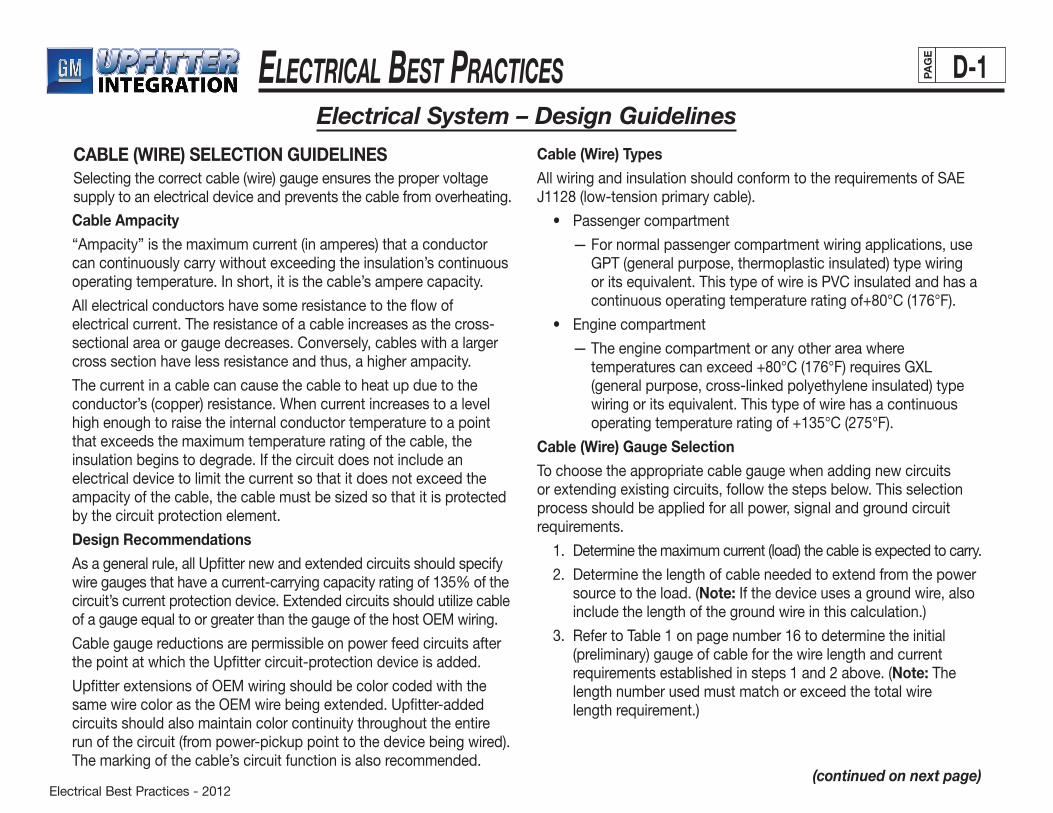
Electrical Best Practices - 2012
ElEctrical BEst PracticEs D-1PAG
E
CABLE (WIRE) SELECTION GUIDELINESSelectingthecorrectcable(wire)gaugeensuresthepropervoltagesupply to an electrical device and prevents the cable from overheating.
Electrical System – Design Guidelines
Cable Ampacity
“Ampacity” is the maximum current (in amperes) that a conductor can continuously carry without exceeding the insulation’s continuous operating temperature. In short, it is the cable’s ampere capacity.
All electrical conductors have some resistance to the flow of electrical current. The resistance of a cable increases as the cross-sectional area or gauge decreases. Conversely, cables with a larger cross section have less resistance and thus, a higher ampacity.
The current in a cable can cause the cable to heat up due to the conductor’s (copper) resistance. When current increases to a level high enough to raise the internal conductor temperature to a point that exceeds the maximum temperature rating of the cable, the insulation begins to degrade. If the circuit does not include an electrical device to limit the current so that it does not exceed the ampacityofthecable,thecablemustbesizedsothatitisprotectedby the circuit protection element.
Design Recommendations
As a general rule, all Upfitter new and extended circuits should specify wiregaugesthathaveacurrent-carryingcapacityratingof135%ofthecircuit’scurrentprotectiondevice.Extendedcircuitsshouldutilizecableof a gauge equal to or greater than the gauge of the host OEM wiring.
Cable gauge reductions are permissible on power feed circuits after the point at which the Upfitter circuit-protection device is added.
Upfitter extensions of OEM wiring should be color coded with the same wire color as the OEM wire being extended. Upfitter-added circuits should also maintain color continuity throughout the entire run of the circuit (from power-pickup point to the device being wired). The marking of the cable’s circuit function is also recommended.
Cable (Wire) Types
AllwiringandinsulationshouldconformtotherequirementsofSAEJ1128(low-tensionprimarycable).
• Passengercompartment
— For normal passenger compartment wiring applications, use GPT (general purpose, thermoplastic insulated) type wiring or its equivalent. This type of wire is PVC insulated and has a continuousoperatingtemperatureratingof+80°C(176°F).
• Enginecompartment
— The engine compartment or any other area where temperaturescanexceed+80°C(176°F)requiresGXL(general purpose, cross-linked polyethylene insulated) type wiring or its equivalent. This type of wire has a continuous operatingtemperatureratingof+135°C(275°F).
Cable (Wire) Gauge Selection
To choose the appropriate cable gauge when adding new circuits or extending existing circuits, follow the steps below. This selection process should be applied for all power, signal and ground circuit requirements.
1. Determine the maximum current (load) the cable is expected to carry.
2. Determine the length of cable needed to extend from the power source to the load. (Note: If the device uses a ground wire, also
include the length of the ground wire in this calculation.)
3. RefertoTable1onpagenumber16todeterminetheinitial(preliminary) gauge of cable for the wire length and current requirements established in steps 1 and 2 above. (Note: The length number used must match or exceed the total wire length requirement.)
(continued on next page)
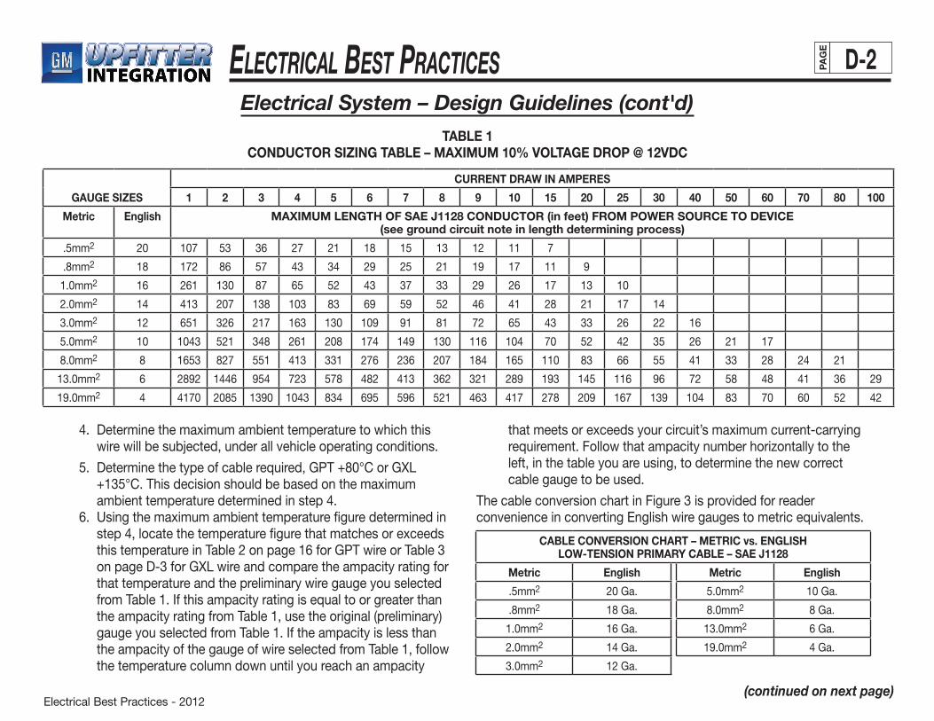
Electrical Best Practices - 2012
ElEctrical BEst PracticEs D-2PAG
E
4. Determinethemaximumambienttemperaturetowhichthiswire will be subjected, under all vehicle operating conditions.
5. Determinethetypeofcablerequired,GPT+80°CorGXL+135°C.Thisdecisionshouldbebasedonthemaximumambienttemperaturedeterminedinstep4.
6. Usingthemaximumambienttemperaturefiguredeterminedinstep4,locatethetemperaturefigurethatmatchesorexceedsthistemperatureinTable2onpage16forGPTwireorTable3onpageD-3forGXLwireandcomparetheampacityratingforthat temperature and the preliminary wire gauge you selected from Table 1. If this ampacity rating is equal to or greater than the ampacity rating from Table 1, use the original (preliminary) gauge you selected from Table 1. If the ampacity is less than the ampacity of the gauge of wire selected from Table 1, follow the temperature column down until you reach an ampacity
that meets or exceeds your circuit’s maximum current-carrying requirement.Followthatampacitynumberhorizontallytotheleft, in the table you are using, to determine the new correct cable gauge to be used.
The cable conversion chart in Figure 3 is provided for reader convenience in converting English wire gauges to metric equivalents.
GAUGE SIZES
CURRENT DRAW IN AMPERES
1 2 3 4 5 6 7 8 9 10 15 20 25 30 40 50 60 70 80 100
Metric English MAXIMUM LENGTH OF SAE J1128 CONDUCTOR (in feet) FROM POWER SOURCE TO DEVICE (see ground circuit note in length determining process)
.5mm2 20 107 53 36 27 21 18 15 13 12 11 7
.8mm2 18 172 86 57 43 34 29 25 21 19 17 11 9
1.0mm2 16 261 130 87 65 52 43 37 33 29 26 17 13 10
2.0mm2 14 413 207 138 103 83 69 59 52 46 41 28 21 17 14
3.0mm2 12 651 326 217 163 130 109 91 81 72 65 43 33 26 22 16
5.0mm2 10 1043 521 348 261 208 174 149 130 116 104 70 52 42 35 26 21 17
8.0mm2 8 1653 827 551 413 331 276 236 207 184 165 110 83 66 55 41 33 28 24 21
13.0mm2 6 2892 1446 954 723 578 482 413 362 321 289 193 145 116 96 72 58 48 41 36 29
19.0mm2 4 4170 2085 1390 1043 834 695 596 521 463 417 278 209 167 139 104 83 70 60 52 42
TABLE 1CONDUCTOR SIZING TABLE – MAXIMUM 10% VOLTAGE DROP @ 12VDC
(continued on next page)
CABLE CONVERSION CHART – METRIC vs. ENGLISH LOW-TENSION PRIMARY CABLE – SAE J1128
Metric English Metric English
.5mm2 20 Ga. 5.0mm2 10 Ga.
.8mm2 18Ga. 8.0mm2 8Ga.
1.0mm2 16Ga. 13.0mm2 6Ga.
2.0mm2 14Ga. 19.0mm2 4Ga.
3.0mm2 12 Ga.
Electrical System – Design Guidelines (cont'd)
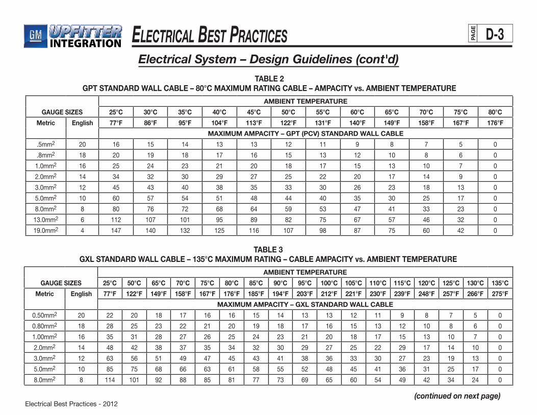
Electrical Best Practices - 2012
ElEctrical BEst PracticEs D-3PAG
E
GAUGE SIZES
AMBIENT TEMPERATURE
25°C 30°C 35°C 40°C 45°C 50°C 55°C 60°C 65°C 70°C 75°C 80°C
Metric English 77°F 86°F 95°F 104°F 113°F 122°F 131°F 140°F 149°F 158°F 167°F 176°F
MAXIMUM AMPACITY – GPT (PCV) STANDARD WALL CABLE
.5mm2 20 16 15 14 13 13 12 11 9 8 7 5 0
.8mm2 18 20 19 18 17 16 15 13 12 10 8 6 0
1.0mm2 16 25 24 23 21 20 18 17 15 13 10 7 0
2.0mm2 14 34 32 30 29 27 25 22 20 17 14 9 0
3.0mm2 12 45 43 40 38 35 33 30 26 23 18 13 0
5.0mm2 10 60 57 54 51 48 44 40 35 30 25 17 0
8.0mm2 8 80 76 72 68 64 59 53 47 41 33 23 0
13.0mm2 6 112 107 101 95 89 82 75 67 57 46 32 0
19.0mm2 4 147 140 132 125 116 107 98 87 75 60 42 0
TABLE 2GPT STANDARD WALL CABLE – 80°C MAXIMUM RATING CABLE – AMPACITY vs. AMBIENT TEMPERATURE
GAUGE SIZES
AMBIENT TEMPERATURE
25°C 50°C 65°C 70°C 75°C 80°C 85°C 90°C 95°C 100°C 105°C 110°C 115°C 120°C 125°C 130°C 135°C
Metric English 77°F 122°F 149°F 158°F 167°F 176°F 185°F 194°F 203°F 212°F 221°F 230°F 239°F 248°F 257°F 266°F 275°F
MAXIMUM AMPACITY – GXL STANDARD WALL CABLE
0.50mm2 20 22 20 18 17 16 16 15 14 13 13 12 11 9 8 7 5 0
0.80mm2 18 28 25 23 22 21 20 19 18 17 16 15 13 12 10 8 6 0
1.00mm2 16 35 31 28 27 26 25 24 23 21 20 18 17 15 13 10 7 0
2.0mm2 14 48 42 38 37 35 34 32 30 29 27 25 22 29 17 14 10 0
3.0mm2 12 63 56 51 49 47 45 43 41 38 36 33 30 27 23 19 13 0
5.0mm2 10 85 75 68 66 63 61 58 55 52 48 45 41 36 31 25 17 0
8.0mm2 8 114 101 92 88 85 81 77 73 69 65 60 54 49 42 34 24 0
TABLE 3GXL STANDARD WALL CABLE – 135°C MAXIMUM RATING – CABLE AMPACITY vs. AMBIENT TEMPERATURE
Electrical System – Design Guidelines (cont'd)
(continued on next page)
Electrical Best Practices - 2012
ElEctrical BEst PracticEs D-4PAG
E
Typical Calculation Example
You have calculated that the maximum load to which your circuit will be subjected is 20 amps and your total circuit wire length is calculated to be 20 feet. Read down the 20 amp column in Table 1 until you find a length of wire that matches or exceeds your 20-foot requirement. In this case it is 21 feet. Read across to the left of this numbertodeterminethewiregaugesizetobeused.Youwillfindittobe14gauge(2.0mm2 metric). This is your initial (preliminary) gauge requirement.
You have determined that the maximum ambient temperature this wirewillbeexposedtois65°C(149°F)andyouopttouseGPTcable.Readdownunderthe65°Ccolumnandacrossfromthe14gauge listing in Table 2 and you find that 17 amps is the maximum ampacityfora14gaugewirethatwillbeexposedtoatemperatureof65°C.As17ampsislessthanyour20amprequirement,continuereadingdownthe65°Ccolumnuntilyoureachanampacitythatmatches or exceeds your 20 amp requirement. In this case it is 23 amps. Read across to the left of this number to determine your new wire gauge requirement which you will find to be 12 gauge (3.0 mm2 metric). This is your new wire gauge requirement.
WIRE HARNESS ASSEMBLY GUIDELINESDesign Recommendations
To help ensure a quality electrical build, GM recommends that Upfitters group individual wires together and bundle them into a harness assembly for their protection. This harness assembly should be pre-assembled outside the vehicle and should be built in accordance withtherecommendationsoutlinedinthe“Cable(Wire)SelectionGuidelines,” “Connecting Guidelines” and “Wire Harness Covering Guidelines” in this section. GM also recommends against the use of common, interchangeable, wire harness assemblies that are
(continued on next page)
not specifically designed and tailored to fit the vehicle into which they will be installed. Universal wiring harness assemblies, that are designed to fit many vehicles and usually incorporate circuits thatare not always required or used, tend to create conditions that are usually detrimental to a quality electrical build (e.g., open, loose connectors that are susceptible to short circuiting and rattling;unprotected excess wire that gets stored in areas of the vehicle where it shouldn’t be and becomes susceptible to damage by hostile vehicle surfaces and/or components; wire takeout points that do not always get located in the vehicle where they should be). The overall result is a wiring installation process that becomes very difficult to implement on a repetitive basis.
CONNECTING GUIDELINESDesign Recommendations
In order to achieve a high degree of reliability, it is essential to use a quality connection system whenever an Upfitter electrical system is installed in a GM vehicle. General Motors strongly recommends using OEM connection system components when adding a wiring system to a GM vehicle.
For greater reliability, it is recommended that Upfitters use single-cavity male/female connectors, rather than butt-splice sleeves, for single wire connection points. (Note: If using butt-splice sleeves, make sure that they comply with the recommendations outlined in the“SplicingGuidelines”subheadinthissectionofthismanual.)
Electrical System – Design Guidelines (cont'd)
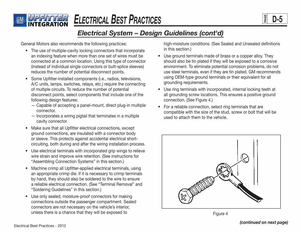
Electrical Best Practices - 2012
ElEctrical BEst PracticEs D-5PAG
E
Electrical System – Design Guidelines (cont'd)
(continued on next page)
General Motors also recommends the following practices:
• Theuseofmultiple-cavitylockingconnectorsthatincorporatean indexing feature when more than one set of wires must be connected at a common location. Using this type of connector (instead of individual single connectors or butt-splice sleeves) reduces the number of potential disconnect points.
• SomeUpfitter-installedcomponents(i.e.,radios,televisions,A/C units, lamps, switches, relays, etc.) require the connecting of multiple circuits. To reduce the number of potential disconnect points, select components that include one of the following design features:
— Capable of accepting a panel-mount, direct plug-in multiple connector.
— Incorporates a wiring pigtail that terminates in a multiple cavity connector.
• MakesurethatallUpfitterelectricalconnections,exceptground connections, are insulated with a connector body or sleeve. This protects against accidental electrical short-circuiting, both during and after the wiring installation process.
• Useelectricalterminalswithincorporatedgripwingstorelievewirestrainandimprovewireretention.(Seeinstructionsfor“AssemblingConnectionSystems”inthissection.)
• MachinecrimpallUpfitter-appliedelectricalterminals,usingan appropriate crimp die. If it is necessary to crimp terminals by hand, they should also be soldered to the wire to ensure areliableelectricalconnection.(See“TerminalRemoval”and“SolderingGuidelines”inthissection.)
• Useonlysealed,moisture-proofconnectorsformakingconnectionsoutsidethepassengercompartment.Sealedconnectors are not necessary on the vehicle’s interior, unless there is a chance that they will be exposed to
high-moistureconditions.(SeeSealedandUnsealeddefinitionsin this section.)
• Usegroundterminalsmadeofbrassoracopperalloy.Theyshould also be tin plated if they will be exposed to a corrosive environment. To eliminate potential corrosion problems, do not use steel terminals, even if they are tin plated. GM recommends using OEM-type ground terminals or their equivalent for all grounding requirements.
• Useringterminalswithincorporated,internallockingteethatall grounding screw locations. This ensures a positive ground connection.(SeeFigure4.)
• Forareliableconnection,selectringterminalsthatarecompatiblewiththesizeofthestud,screworboltthatwillbeused to attach them to the vehicle.
Figure4

Electrical Best Practices - 2012
ElEctrical BEst PracticEs D-6PAG
E
Electrical System – Design Guidelines (cont'd)
(continued on next page)
CONNECTOR TYPESReplace with GM Original Equipment (OE) connection systems, utilizingbothsealedandunsealedconnectors.
Unsealed ConnectorsUnsealedconnections(Figure5)aredesignedforuseintheinteriorof the vehicle. If used elsewhere, environmental factors, such as moisture and grit, can cause corrosion to build up, leading to a poorconnection. Corroded terminals create high resistance in the connection, which in turn can cause intermittent or open circuits.
Figure5
Figure6
Sealed ConnectorsSealedconnectionsystems(Figure6)aredesignedwithenviron-mental seals to keep out moisture and grit. This makes them ideal for use outside the vehicle’s passenger compartment. Built into this type of connector are two types of seals:
• Aconnectorsealwhichprovidesanenvironmentalsealbetween the mating connectors.
• Acablesealwhichsealstheareawhereeachwireenterstheconnector.
General Motors recommends using sealed connection systems in areas exposed to the outside environment.
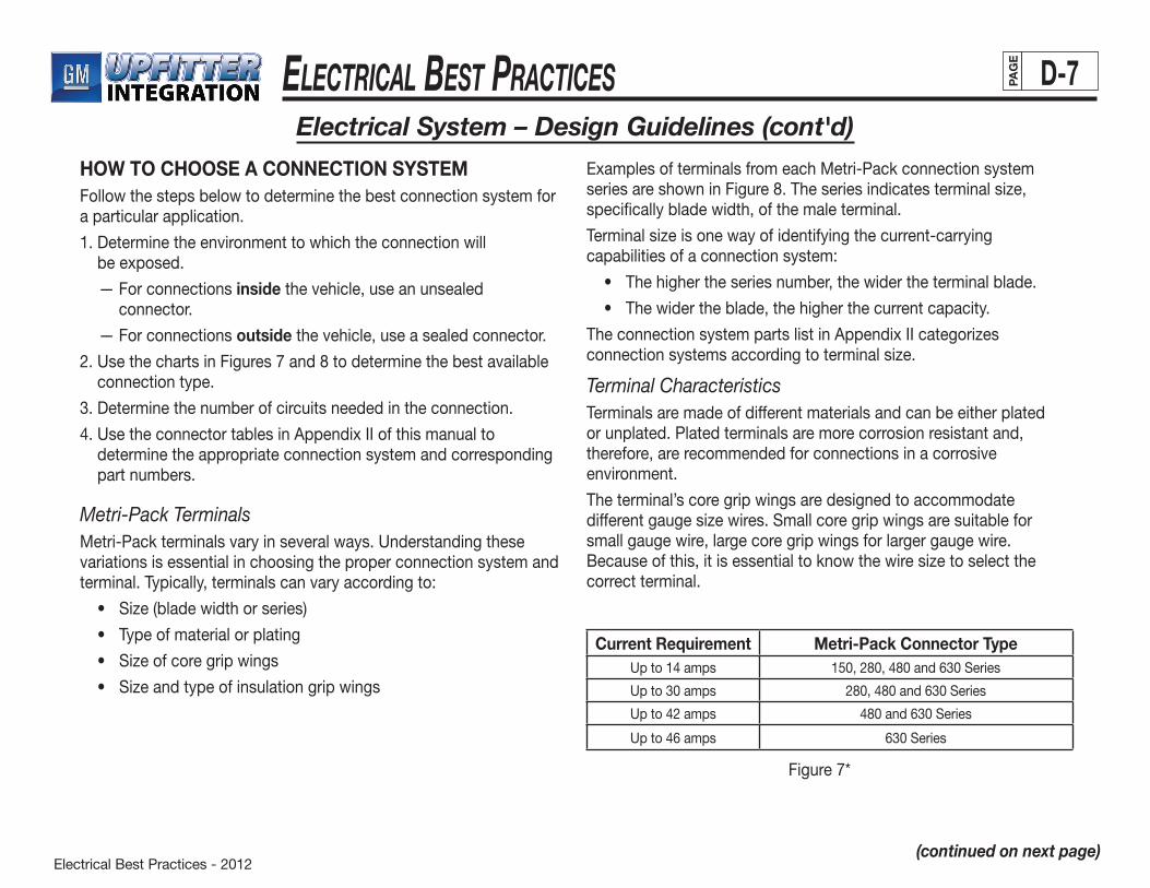
Electrical Best Practices - 2012
ElEctrical BEst PracticEs D-7PAG
E
Electrical System – Design Guidelines (cont'd)
(continued on next page)
HOW TO CHOOSE A CONNECTION SYSTEMFollow the steps below to determine the best connection system for a particular application.
1. Determine the environment to which the connection will be exposed.
— For connections inside the vehicle, use an unsealed connector.
— For connections outside the vehicle, use a sealed connector.
2.UsethechartsinFigures7and8todeterminethebestavailableconnection type.
3. Determine the number of circuits needed in the connection.
4.UsetheconnectortablesinAppendixIIofthismanualtodetermine the appropriate connection system and corresponding part numbers.
Metri-Pack TerminalsMetri-Pack terminals vary in several ways. Understanding these variations is essential in choosing the proper connection system and terminal. Typically, terminals can vary according to:
• Size(bladewidthorseries)
• Typeofmaterialorplating
• Sizeofcoregripwings
• Sizeandtypeofinsulationgripwings
Examples of terminals from each Metri-Pack connection system seriesareshowninFigure8.Theseriesindicatesterminalsize,specifically blade width, of the male terminal.
Terminalsizeisonewayofidentifyingthecurrent-carryingcapabilities of a connection system:
• Thehighertheseriesnumber,thewidertheterminalblade.
• Thewidertheblade,thehigherthecurrentcapacity.
TheconnectionsystempartslistinAppendixIIcategorizesconnectionsystemsaccordingtoterminalsize.
Terminal CharacteristicsTerminals are made of different materials and can be either plated or unplated. Plated terminals are more corrosion resistant and, therefore, are recommended for connections in a corrosiveenvironment.
The terminal’s core grip wings are designed to accommodate differentgaugesizewires.Smallcoregripwingsaresuitableforsmall gauge wire, large core grip wings for larger gauge wire. Becauseofthis,itisessentialtoknowthewiresizetoselectthecorrect terminal.
Current Requirement Metri-Pack Connector TypeUpto14amps 150,280,480and630Series
Up to 30 amps 280,480and630Series
Upto42amps 480and630Series
Upto46amps 630Series
Figure 7*

Electrical Best Practices - 2012
ElEctrical BEst PracticEs D-8PAG
E
Electrical System – Design Guidelines (cont'd)
(continued on next page)
METRI-PACK TERMINALS
SERIES 150 280 480 630
MALE
FEMALE
MAXIMUMCURRENT
RATING14AMPS 30AMPS 42AMPS 46AMPS
Figure8**Note for Figures 7 and 8: These values may vary depending on the environment in which the terminals are used (e.g., engine compartment, cab, chassis, etc.) due to temperature effects and other considerations. It is recommended that the upfitter test the terminal in the application in which it is intended to be used to ensure that the current capacity is adequate.
The current draw of each circuit in a connector system must first be known to enable the correct terminal series to be selected. GM recommendstheuseoftheMetri-pack150seriesforallcircuitsthatdraw14amperesorlessofcurrent.Insulationgripwingsaredesignedto be crimped over the wire insulation in an unsealed connection system, and over the cable seal in a sealed connection system. Terminals meant for use in a sealed system are not interchangeable with those intended for an unsealed system.
Insulation grip wings for sealed systems are generally larger than their unsealed system counterparts. The more rounded shape of the larger grip wings allows them to work well with the round cable seal used in a sealed system.
Due to the many factors involved in the selection of terminals and cable seals, terminal and cable seal part numbers are not includedinConnectorSystemPartsList(AppendixII).Forreader convenience in determining the correct terminal usage, a millimeter-to-inches conversion table for cable outside diameter follows (Figure 9).
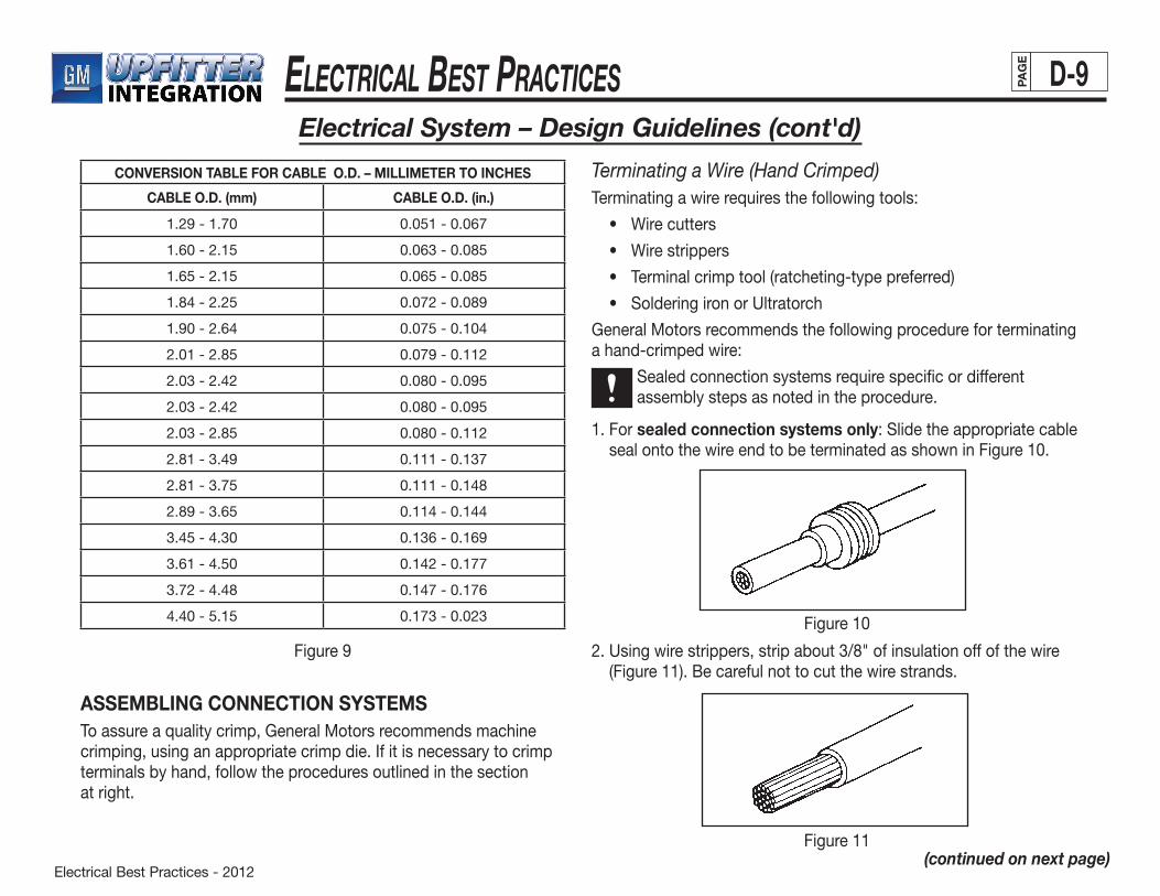
Electrical Best Practices - 2012
ElEctrical BEst PracticEs D-9PAG
E
Electrical System – Design Guidelines (cont'd)
(continued on next page)
CONVERSION TABLE FOR CABLE O.D. – MILLIMETER TO INCHES
CABLE O.D. (mm) CABLE O.D. (in.)
1.29 - 1.70 0.051-0.067
1.60-2.15 0.063-0.085
1.65-2.15 0.065-0.085
1.84-2.25 0.072-0.089
1.90-2.64 0.075-0.104
2.01-2.85 0.079 - 0.112
2.03-2.42 0.080-0.095
2.03-2.42 0.080-0.095
2.03-2.85 0.080-0.112
2.81-3.49 0.111 - 0.137
2.81-3.75 0.111-0.148
2.89-3.65 0.114-0.144
3.45-4.30 0.136-0.169
3.61-4.50 0.142-0.177
3.72-4.48 0.147-0.176
4.40-5.15 0.173 - 0.023
Figure 9
ASSEMBLING CONNECTION SYSTEMSTo assure a quality crimp, General Motors recommends machine crimping, using an appropriate crimp die. If it is necessary to crimp terminals by hand, follow the procedures outlined in the sectionat right.
2.Usingwirestrippers,stripabout3/8"ofinsulationoffofthewire(Figure 11). Be careful not to cut the wire strands.
Terminating a Wire (Hand Crimped)Terminating a wire requires the following tools:
• Wirecutters
• Wirestrippers
• Terminalcrimptool(ratcheting-typepreferred)
• SolderingironorUltratorch
General Motors recommends the following procedure for terminating a hand-crimped wire:
Sealedconnectionsystemsrequirespecificordifferent assembly steps as noted in the procedure.
1. For sealed connection systems only:Slidetheappropriatecableseal onto the wire end to be terminated as shown in Figure 10.
Figure 10
Figure 11
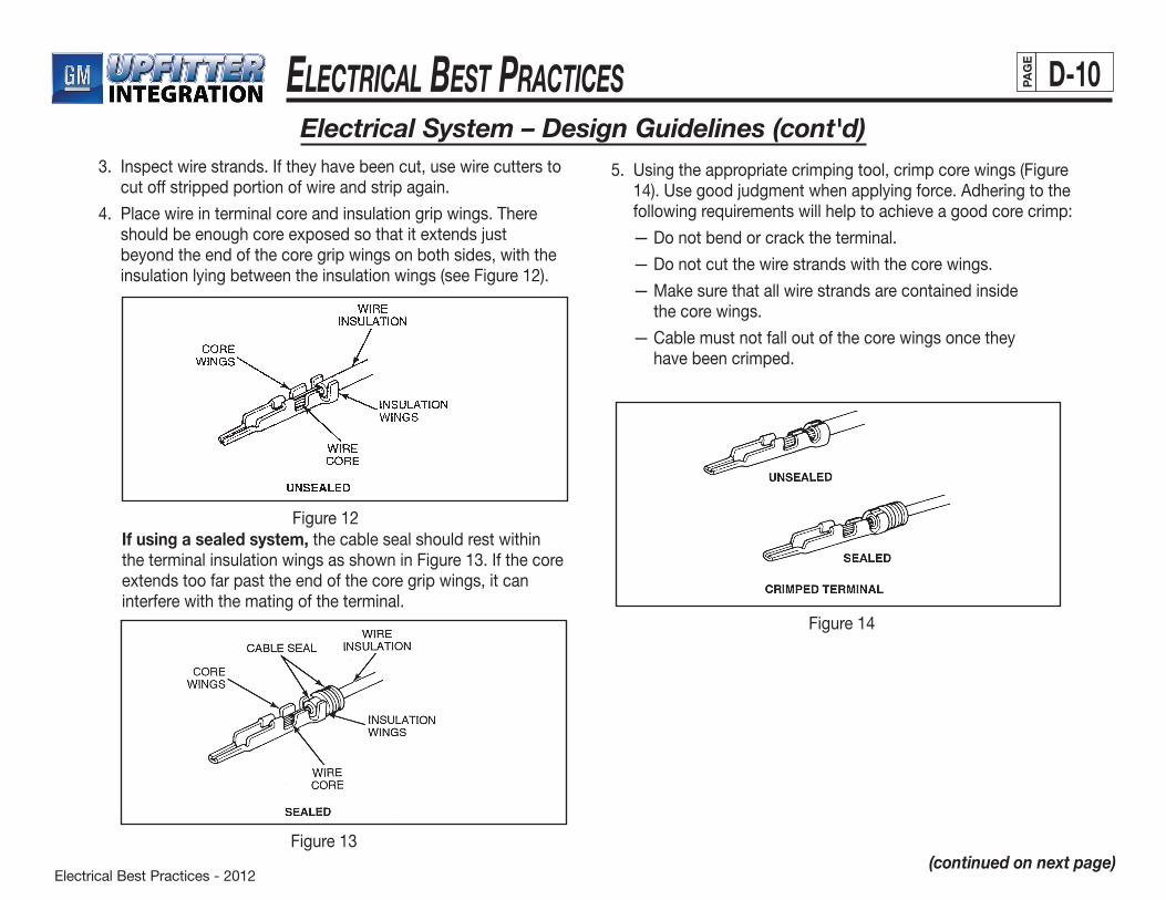
Electrical Best Practices - 2012
ElEctrical BEst PracticEs D-10PAG
E
Electrical System – Design Guidelines (cont'd)
(continued on next page)
3. Inspect wire strands. If they have been cut, use wire cutters to cut off stripped portion of wire and strip again.
4. Placewireinterminalcoreandinsulationgripwings.Thereshould be enough core exposed so that it extends just beyond the end of the core grip wings on both sides, with the insulation lying between the insulation wings (see Figure 12).
If using a sealed system, the cable seal should rest within the terminal insulation wings as shown in Figure 13. If the core extends too far past the end of the core grip wings, it can interfere with the mating of the terminal.
Figure 12
5. Usingtheappropriatecrimpingtool,crimpcorewings(Figure14).Usegoodjudgmentwhenapplyingforce.Adheringtothefollowing requirements will help to achieve a good core crimp:
— Do not bend or crack the terminal.
— Do not cut the wire strands with the core wings.
— Make sure that all wire strands are contained inside the core wings.
— Cable must not fall out of the core wings once they have been crimped.
Figure14
Figure 13

Electrical Best Practices - 2012
ElEctrical BEst PracticEs D-11PAG
E
Electrical System – Design Guidelines (cont'd)
(continued on next page)
CAUTION
6.CrimpinsulationwingsusingthesameprocedureasoutlinedinStep5.Notethatthecrimpsizeislargerforsealedterminalinsulation wings than for unsealed. The following will aid in achieving a good insulation crimp:
— Do not cut into the wire insulation.
— Do not bend or crack the terminal.
— Terminal must contact insulation on both top and bottom of crimp area.
— Do not cut into the cable seal (sealed connection systems only).
7.Solderallhand-crimpedterminals.Propersolderingtechniquesareoutlinedin“SolderingGuidelines”inthissection.
Be careful not to use too much solder as wicking can occur. Avoid getting solder on the terminal’s mating interface.
SOLDERING GUIDELINESProduction crimps generally do not require soldering because the crimp is made with precision tooling. Hand-crimping cannot meet the same quality standards. Therefore, soldering is recommended toproduce reliable connections in hand-crimped terminals.
Solderingacrimpisimportantfortworeasons:
• Itprovidesamechanicalbondbetweentheterminalandthe wire. This helps to prevent wires from pulling loose and causing an open circuit.
• Itreducesthepossibilityofcorrosion-relatedproblems.As the core becomes more corroded, the wire develops a higher resistance to current flow. This may cause electrical components to function improperly.
Soldering ProceduresSolderingaterminalrequiresasolderingiron.Therecommendedprocedure is:
1. Allow soldering tool to preheat for at least one minute. Preheating promotes good, even solder flow.
Do not use a soldering gun to solder terminals. Even at low settings, soldering gun temperatures are too high for this application.
2. Heat the terminal core wings and wire core. Avoid heating too close to the wire insulation. Burned or melted insulation can lead to short circuits, open circuits, or corrosion within the wire, resulting in high resistance.
3. ApplysoldertocorewingsasshowninFigure15.Use just enough solder to obtain even solder flow through the
core wings.
Use only rosin core/rosin flux solder for soldering terminals. Other flux materials can cause corrosion.
Avoid using too much solder which can result in “wicking.” Wicking results when excessive solder is applied to the terminal and it begins to travel up the wire core, like candle wax up a wick. This can cause the wire to become stiff or brittle and produce a flex point. Eventually, this can lead to a broken wire and an open circuit.
Do not get solder on terminal mating surfaces.
CAUTION
CAUTION
CAUTION
CAUTION
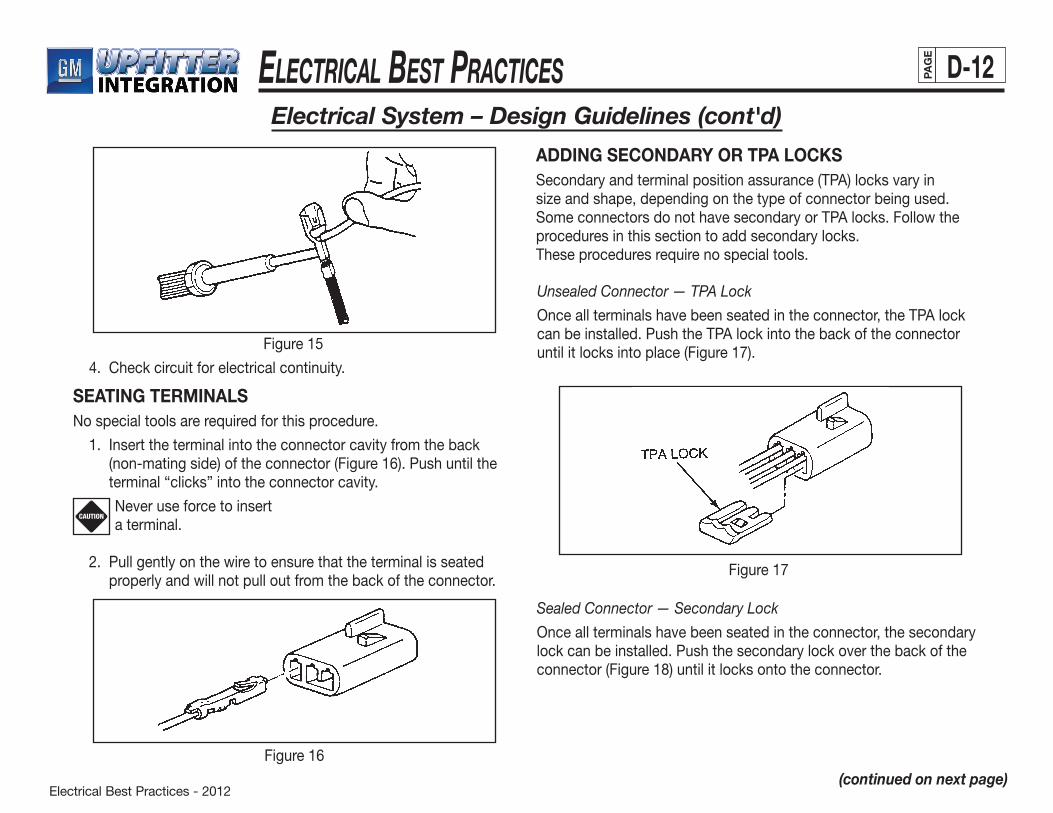
Electrical Best Practices - 2012
ElEctrical BEst PracticEs D-12PAG
E
Electrical System – Design Guidelines (cont'd)
(continued on next page)
Figure15
Figure16
4. Checkcircuitforelectricalcontinuity.
SEATING TERMINALSNo special tools are required for this procedure.
1. Insert the terminal into the connector cavity from the back (non-matingside)oftheconnector(Figure16).Pushuntilthe terminal “clicks” into the connector cavity.
Never use force to insert a terminal.
2. Pull gently on the wire to ensure that the terminal is seated properly and will not pull out from the back of the connector.
CAUTION
ADDING SECONDARY OR TPA LOCKSSecondaryandterminalpositionassurance(TPA)locksvaryinsizeandshape,dependingonthetypeofconnectorbeingused.SomeconnectorsdonothavesecondaryorTPAlocks.Followtheprocedures in this section to add secondary locks.These procedures require no special tools.
Unsealed Connector — TPA Lock
Once all terminals have been seated in the connector, the TPA lock can be installed. Push the TPA lock into the back of the connector until it locks into place (Figure 17).
Sealed Connector — Secondary Lock
Once all terminals have been seated in the connector, the secondary lock can be installed. Push the secondary lock over the back of the connector(Figure18)untilitlocksontotheconnector.
Figure 17
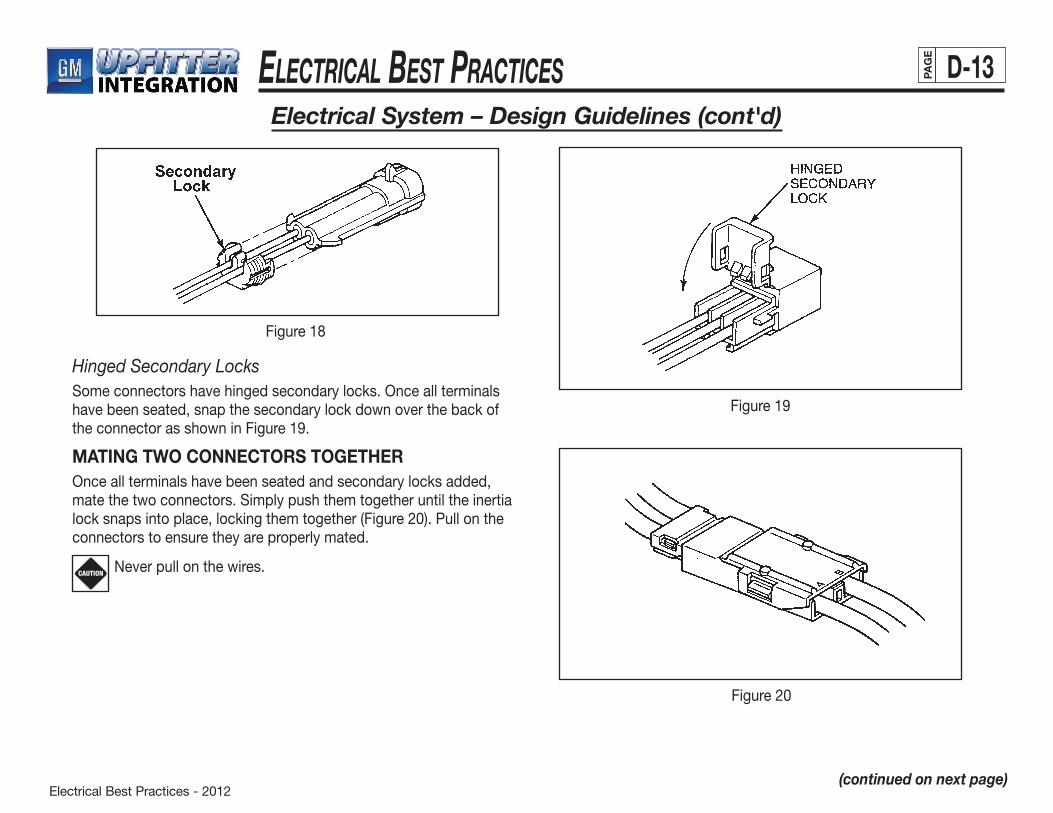
Electrical Best Practices - 2012
ElEctrical BEst PracticEs D-13PAG
E
Figure18
Electrical System – Design Guidelines (cont'd)
(continued on next page)
Hinged Secondary LocksSomeconnectorshavehingedsecondarylocks.Onceallterminalshave been seated, snap the secondary lock down over the back of the connector as shown in Figure 19.
MATING TWO CONNECTORS TOGETHEROnce all terminals have been seated and secondary locks added, matethetwoconnectors.Simplypushthemtogetheruntiltheinertialock snaps into place, locking them together (Figure 20). Pull on the connectors to ensure they are properly mated.
Never pull on the wires.CAUTION
Figure 19
Figure 20
Electrical Best Practices - 2012
ElEctrical BEst PracticEs D-14PAG
E
Electrical System – Design Guidelines (cont'd)
(continued on next page)
DISASSEMBLING CONNECTION SYSTEMSThis procedure can be done using a small screwdriver or pick.
• Toremoveaconnectorpositionassurance(CPA)lock—Removethe CPA lock by simply depressing the tabs on either side and pullingthelockoutoftheconnection.(SeeFigure21.)
• Todisconnectaconnector—Usingyourthumborasmallscrewdriver or pick, lift up on the inertia lock tab. Pull the connectors apart.
Removing TPA or Secondary Locks • ToremoveaTPAlock—Usingasmallscrewdriverorpick,
carefully depress the locking tabs on either side of the connector.(SeeFigure22.)RemovetheTPAlockfromtheback side of the connector.
Figure 22
• Toremoveasecondarylock—Useasmallscrewdriverorpickto carefully lift the secondary lock over the locking tabs on eithersideoftheconnectorandremove.(SeeFigure23.)
Be careful not to bend or deform the locks or connectors if they are to be used again.CAUTION
Figure 21
Figure 23
Electrical Best Practices - 2012
ElEctrical BEst PracticEs D-15PAG
E
Electrical System – Design Guidelines (cont'd)
(continued on next page)
TERMINAL REMOVAL Specialtoolsarerequiredtoremovetheterminalwithoutdamagingit or the connector in which it is inserted. Because connectors are designed to firmly retain terminals, it is sometimes difficult to remove them. Different style terminals have different removal procedures, but most common terminals can be removed using the procedure below. This procedure will work with all parts in the connection systems parts list (Appendix II).
A terminal removal tool (e.g., pick or safety pin) is required to remove a push-to-seat terminal from a Metri-Pack connector.
1. Disconnect the mating connector.
2. Remove any secondary or TPA lock.
3. Grasp the wire and push the terminal to the foremost position in the connector cavity. Hold the terminal in this position. The terminal locking tang is now separated from the ridge inside the connector cavity. This makes it easy for the terminal removal tool to unseat the terminal.
4. Locatetheterminallocktangintheconnectorcavitychannelby looking into the connector from the mating end.
5. Insertanappropriatelysizedpickstraightintotheconnectorcavityfromthematingendoftheconnector(Figure24).
6. Depressthelocktangwiththepickorpintounseattheterminal.
7. Gently pull the wire to remove the terminal through the back of the connector.
If force is required to remove the terminal, the locking tang has not been properly depressed. Forcing a terminal out of the connector can damage the cavity walls.
CAUTION
Figure24
Splicing Guidelines
As mentioned earlier, General Motors recommends against splicing into OEM wiring to add or extend a circuit. However, if no other method is available, splicing should comply with the proceduresrecommended in this section.
To ensure a reliable connection, do not use Quicksplice, Scotchlock,wirenutsand/orsimilarsplicingdevicesinGeneral Motors vehicles.
Splicing Two Wires
The crimp-and-seal splice sleeve is recommended for splicing two wires together. It has several advantages, including:
• Itiseasytouse.Onlyonepartisneededtocompletethesplice and it does not require soldering.
• Whenheated,theglue-linedsleevebondstothewireinsulation, creating an excellent environmental seal. This makes it perfect for use both inside and outside the vehicle.
• Thebondbetweenthespliceandthewire,addedtothewirecrimp, creates a very strong splice.
Electrical Best Practices - 2012
ElEctrical BEst PracticEs D-16PAG
E
The table in Figure 27 lists available crimp-and-seal splice sleeves. As previously noted, these parts include a glue-lined tube that, when heated, shrinks over the wires to seal them off from the environment. To assure reliable splicing, always select the splice sleeveproperlysizedanddesignedforthewiregaugeinuse.
The butt-splice sleeve can be used for applications that do not require sealing, such as those inside the passenger compartment of the vehicle. It does not, however, create as strong a splice as that of the crimp-and-seal splice. Do not use unsealed buttsplice sleeves for splices that will be located outside the passenger compartment of the vehicle.
Electrical System – Design Guidelines (cont'd)
(continued on next page)
Figure25
Recommended splicing procedure:
1. Stripabout3/8"oftheinsulationfromtheendsofthetwo wirestobespliced(Figure25).
2. Insert stripped wires into the splice sleeve until they reach thewirestoplocatedatthecenterofthesleeve(Figure26).
Figure26
CRIMP-AND-SEAL SPLICE SLEEVE
PART NUMBER SLEEVE COLORWIRE SIZE
English Metric
12089189 Salmon 18-20 0.80-0.50
12089190 Blue 14-16 2.00-1.00
12089191 Yellow 10-12 5.00-3.00
Figure 27
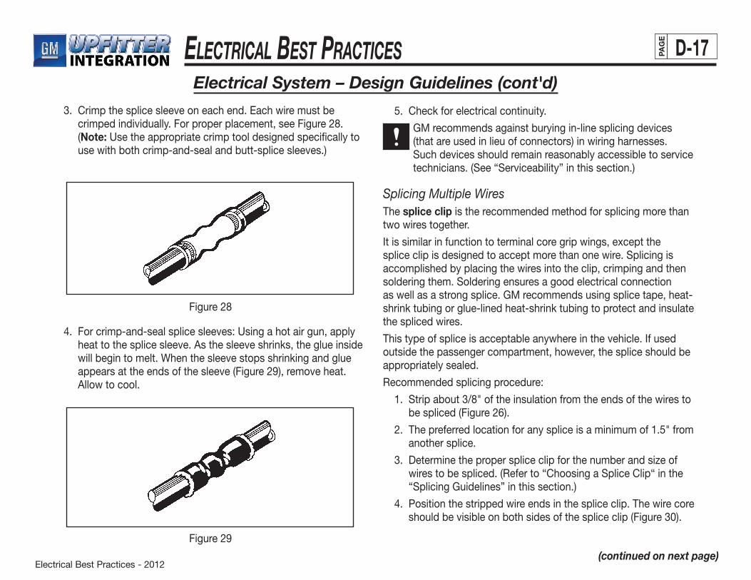
Electrical Best Practices - 2012
ElEctrical BEst PracticEs D-17PAG
E
Electrical System – Design Guidelines (cont'd)
(continued on next page)
3. Crimp the splice sleeve on each end. Each wire must be crimpedindividually.Forproperplacement,seeFigure28.(Note: Use the appropriate crimp tool designed specifically to use with both crimp-and-seal and butt-splice sleeves.)
4. Forcrimp-and-sealsplicesleeves:Usingahotairgun,applyheat to the splice sleeve. As the sleeve shrinks, the glue inside will begin to melt. When the sleeve stops shrinking and glue appears at the ends of the sleeve (Figure 29), remove heat. Allow to cool.
5. Checkforelectricalcontinuity.
GM recommends against burying in-line splicing devices (that are used in lieu of connectors) in wiring harnesses. Suchdevicesshouldremainreasonablyaccessibletoservicetechnicians.(See“Serviceability”inthissection.)
Splicing Multiple WiresThe splice clip is the recommended method for splicing more than two wires together.
It is similar in function to terminal core grip wings, except the spliceclipisdesignedtoacceptmorethanonewire.Splicingisaccomplished by placing the wires into the clip, crimping and then solderingthem.Solderingensuresagoodelectricalconnectionas well as a strong splice. GM recommends using splice tape, heat-shrink tubing or glue-lined heat-shrink tubing to protect and insulate the spliced wires.
This type of splice is acceptable anywhere in the vehicle. If used outside the passenger compartment, however, the splice should be appropriately sealed.
Recommended splicing procedure:
1. Stripabout3/8"oftheinsulationfromtheendsofthewirestobespliced(Figure26).
2. Thepreferredlocationforanyspliceisaminimumof1.5"fromanother splice.
3. Determinetheproperspliceclipforthenumberandsizeofwirestobespliced.(Referto“ChoosingaSpliceClip“inthe“SplicingGuidelines”inthissection.)
4. Positionthestrippedwireendsinthespliceclip.Thewirecoreshould be visible on both sides of the splice clip (Figure 30).
Figure28
Figure 29
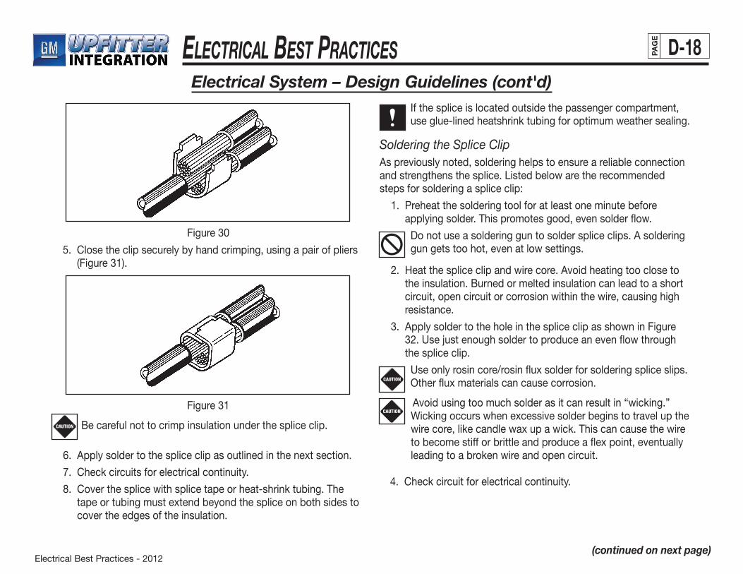
Electrical Best Practices - 2012
ElEctrical BEst PracticEs D-18PAG
E
5. Closetheclipsecurelybyhandcrimping,usingapairofpliers(Figure 31).
Electrical System – Design Guidelines (cont'd)
(continued on next page)
Figure 30
Figure 31
Be careful not to crimp insulation under the splice clip.
6. Applysoldertothespliceclipasoutlinedinthenextsection.
7. Check circuits for electrical continuity.
8. Coverthesplicewithsplicetapeorheat-shrinktubing.Thetape or tubing must extend beyond the splice on both sides to cover the edges of the insulation.
CAUTION
If the splice is located outside the passenger compartment, use glue-lined heatshrink tubing for optimum weather sealing.
Soldering the Splice ClipAs previously noted, soldering helps to ensure a reliable connection andstrengthensthesplice.Listedbelowaretherecommendedsteps for soldering a splice clip:
1. Preheat the soldering tool for at least one minute before applying solder. This promotes good, even solder flow.
Do not use a soldering gun to solder splice clips. A soldering gun gets too hot, even at low settings.
2. Heat the splice clip and wire core. Avoid heating too close to the insulation. Burned or melted insulation can lead to a short circuit, open circuit or corrosion within the wire, causing high resistance.
3. Apply solder to the hole in the splice clip as shown in Figure 32. Use just enough solder to produce an even flow through the splice clip.
Use only rosin core/rosin flux solder for soldering splice slips. Other flux materials can cause corrosion.
CAUTION
Avoid using too much solder as it can result in “wicking.” Wicking occurs when excessive solder begins to travel up the wire core, like candle wax up a wick. This can cause the wire
to become stiff or brittle and produce a flex point, eventually leading to a broken wire and open circuit.
4. Checkcircuitforelectricalcontinuity.
CAUTION

Electrical Best Practices - 2012
ElEctrical BEst PracticEs D-19PAG
E
Figure 32
Electrical System – Design Guidelines (cont'd)
(continued on next page)
Choosing a Splice ClipChoosing the right splice clip is extremely important to the overall durability and quality of the splice. Always consider the number and sizeofwirestobesplicedwhenmakingaselection.
To determine the best typical splice clip for a particular application, calculate the area of the wire’s cross section. Use the optimum range in the table below (Figure 33) to determine the appropriate splice clip part number. The wire cross-sectional areas shown in Figure34areforcable.Typicalcablesdonotvarymuchfromthesenumbers.Simplyaddupthecross-sectionalareaforeachwireinthe splice to get the total cross-sectional area for the splice.
SPLICE CLIP
PART NUMBERSPLICE CROSS-SECTIONAL AREA mm2
OPTIMUM ALLOWABLE
05297428 2.16-3.29 1.35-3.55
00821240 2.80-5.50 2.40-6.45
01839906 5.50-8.90 4.0-10.85
01864022 8.90-12.15 7.0-12.45
05290433 12.15-19.35 9.4-21.3
02962985 21.3-35.0 16.0-44.75
Figure 33
WIRE SIZE CROSS-SECTIONAL AREA (mm2)ENGLISH (GAUGE) METRIC (mm2)
22 0.35 0.308
20 0.50 0.549
18 0.80 0.805
16 1.00 1.177
14 2.00 1.947
12 3.00 3.019
10 5.00 4.757
Figure34
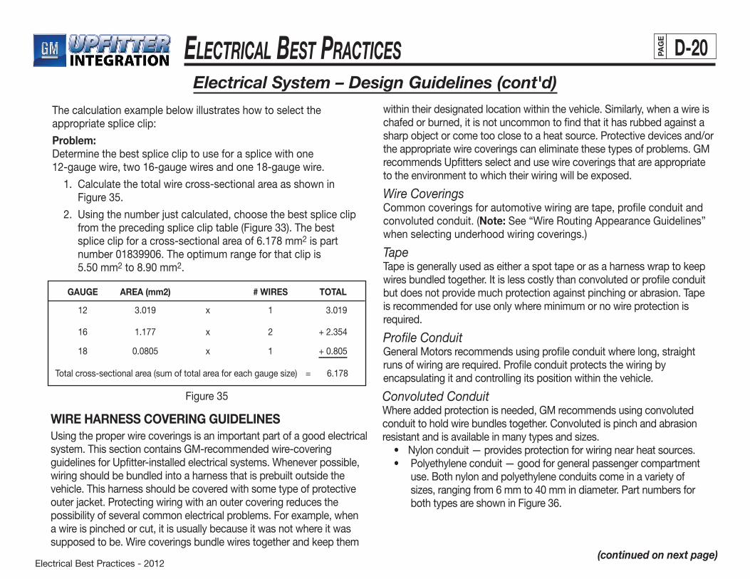
Electrical Best Practices - 2012
ElEctrical BEst PracticEs D-20PAG
E
Electrical System – Design Guidelines (cont'd)
(continued on next page)
The calculation example below illustrates how to select the appropriate splice clip:
Problem: Determine the best splice clip to use for a splice with one 12-gaugewire,two16-gaugewiresandone18-gaugewire.
1. Calculate the total wire cross-sectional area as shown in Figure35.
2. Using the number just calculated, choose the best splice clip from the preceding splice clip table (Figure 33). The best spliceclipforacross-sectionalareaof6.178mm2 is part number01839906.Theoptimumrangeforthatclipis 5.50mm2to8.90mm2.
GAUGE AREA (mm2) # WIRES TOTAL
12 3.019 x 1 3.019
16 1.177 x 2 +2.354
18 0.0805 x 1 +0.805
Totalcross-sectionalarea(sumoftotalareaforeachgaugesize) =6.178
Figure35
WIRE HARNESS COVERING GUIDELINESUsing the proper wire coverings is an important part of a good electrical system. This section contains GM-recommended wire-covering guidelines for Upfitter-installed electrical systems. Whenever possible, wiring should be bundled into a harness that is prebuilt outside the vehicle. This harness should be covered with some type of protective outer jacket. Protecting wiring with an outer covering reduces the possibility of several common electrical problems. For example, when a wire is pinched or cut, it is usually because it was not where it was supposed to be. Wire coverings bundle wires together and keep them
withintheirdesignatedlocationwithinthevehicle.Similarly,whenawireischafed or burned, it is not uncommon to find that it has rubbed against a sharp object or come too close to a heat source. Protective devices and/or the appropriate wire coverings can eliminate these types of problems. GM recommends Upfitters select and use wire coverings that are appropriate to the environment to which their wiring will be exposed.
Wire CoveringsCommon coverings for automotive wiring are tape, profile conduit and convoluted conduit. (Note:See“WireRoutingAppearanceGuidelines”when selecting underhood wiring coverings.)
TapeTape is generally used as either a spot tape or as a harness wrap to keep wires bundled together. It is less costly than convoluted or profile conduit but does not provide much protection against pinching or abrasion. Tape is recommended for use only where minimum or no wire protection is required.
Profile ConduitGeneral Motors recommends using profile conduit where long, straight runs of wiring are required. Profile conduit protects the wiring by encapsulating it and controlling its position within the vehicle.
Convoluted ConduitWhere added protection is needed, GM recommends using convoluted conduit to hold wire bundles together. Convoluted is pinch and abrasion resistantandisavailableinmanytypesandsizes. • Nylonconduit—providesprotectionforwiringnearheatsources. • Polyethyleneconduit—goodforgeneralpassengercompartment
use. Both nylon and polyethylene conduits come in a variety of sizes,rangingfrom6mmto40mmindiameter.PartnumbersforbothtypesareshowninFigure36.
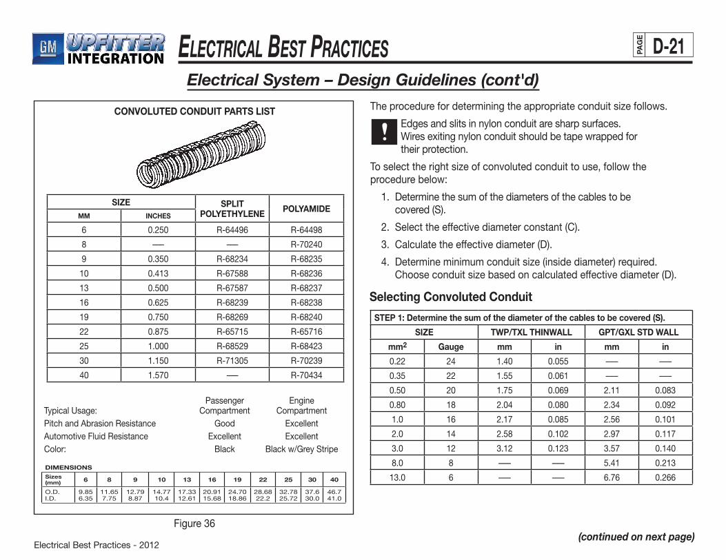
Electrical Best Practices - 2012
ElEctrical BEst PracticEs D-21PAG
E
Electrical System – Design Guidelines (cont'd)
(continued on next page)Figure36
CONVOLUTED CONDUIT PARTS LIST
SIZE SPLIT POLYETHYLENE POLYAMIDE
MM INCHES
6 0.250 R-64496 R-64498
8 ––– ––– R-70240
9 0.350 R-68234 R-68235
10 0.413 R-67588 R-68236
13 0.500 R-67587 R-68237
16 0.625 R-68239 R-68238
19 0.750 R-68269 R-68240
22 0.875 R-65715 R-65716
25 1.000 R-68529 R-68423
30 1.150 R-71305 R-70239
40 1.570 ––– R-70434
Passenger EngineTypical Usage: Compartment CompartmentPitch and Abrasion Resistance Good ExcellentAutomotive Fluid Resistance Excellent ExcellentColor: Black Blackw/GreyStripe
DIMENSIONS
Sizes(mm) 6 8 9 10 13 16 19 22 25 30 40
O.D.I.D.
9.856.35
11.657.75
12.798.87
14.7710.4
17.3312.61
20.9115.68
24.7018.86
28.6822.2
32.7825.72
37.630.0
46.741.0
Theprocedurefordeterminingtheappropriateconduitsizefollows.
Edges and slits in nylon conduit are sharp surfaces. Wires exiting nylon conduit should be tape wrapped for their protection.
Toselecttherightsizeofconvolutedconduittouse,followtheprocedure below:
1. Determine the sum of the diameters of the cables to be covered(S).
2. Selecttheeffectivediameterconstant(C).
3. Calculate the effective diameter (D).
4. Determineminimumconduitsize(insidediameter)required.Chooseconduitsizebasedoncalculatedeffectivediameter(D).
Selecting Convoluted Conduit
STEP 1: Determine the sum of the diameter of the cables to be covered (S).
SIZE TWP/TXL THINWALL GPT/GXL STD WALL
mm2 Gauge mm in mm in
0.22 24 1.40 0.055 ––– –––
0.35 22 1.55 0.061 ––– –––
0.50 20 1.75 0.069 2.11 0.083
0.80 18 2.04 0.080 2.34 0.092
1.0 16 2.17 0.085 2.56 0.101
2.0 14 2.58 0.102 2.97 0.117
3.0 12 3.12 0.123 3.57 0.140
8.0 8 ––– ––– 5.41 0.213
13.0 6 ––– ––– 6.76 0.266
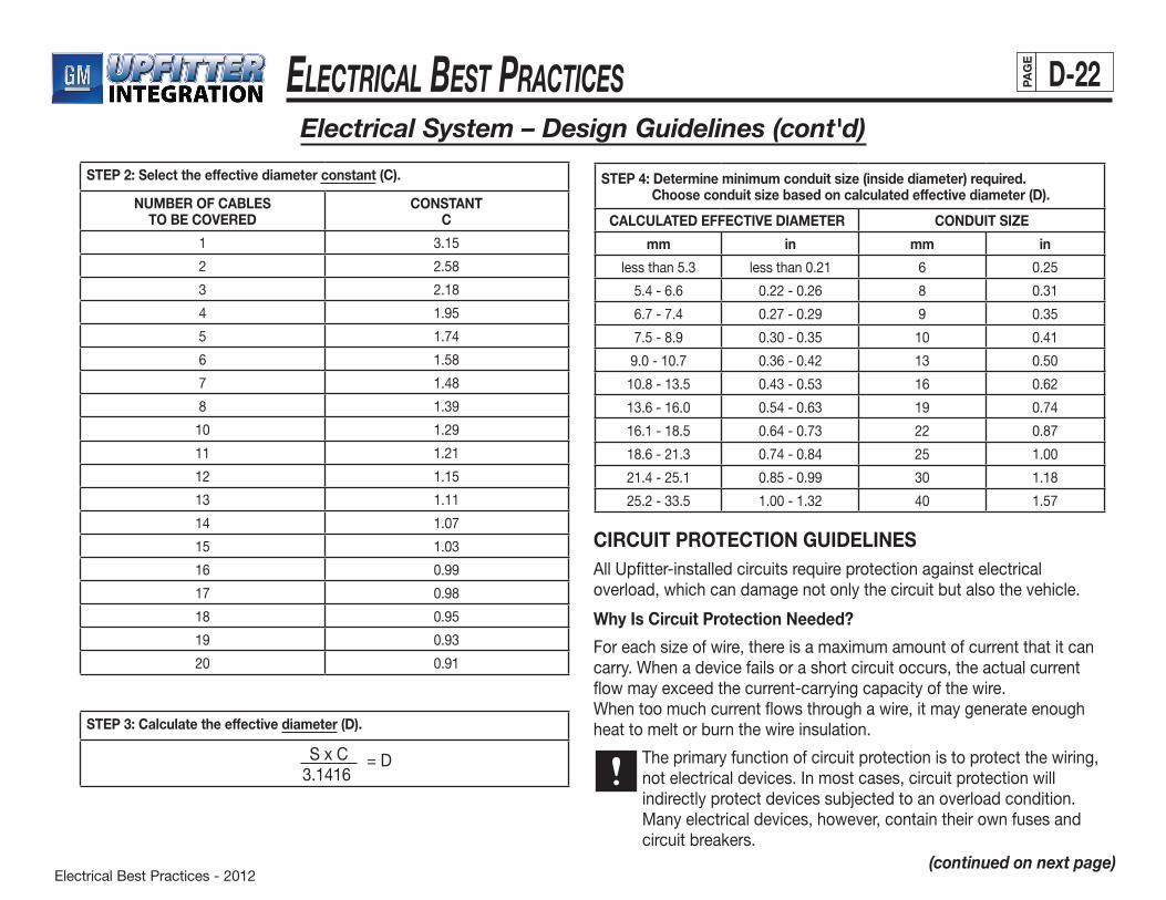
Electrical Best Practices - 2012
ElEctrical BEst PracticEs D-22PAG
E
Electrical System – Design Guidelines (cont'd)
(continued on next page)
STEP 2: Select the effective diameter constant (C).
NUMBER OF CABLESTO BE COVERED
CONSTANTC
1 3.15
2 2.58
3 2.18
4 1.95
5 1.74
6 1.58
7 1.48
8 1.39
10 1.29
11 1.21
12 1.15
13 1.11
14 1.07
15 1.03
16 0.99
17 0.98
18 0.95
19 0.93
20 0.91
STEP 3: Calculate the effective diameter (D).
SxC3.1416
= D
STEP 4: Determine minimum conduit size (inside diameter) required. Choose conduit size based on calculated effective diameter (D).
CALCULATED EFFECTIVE DIAMETER CONDUIT SIZE
mm in mm in
lessthan5.3 less than 0.21 6 0.25
5.4-6.6 0.22-0.26 8 0.31
6.7-7.4 0.27 - 0.29 9 0.35
7.5-8.9 0.30-0.35 10 0.41
9.0 - 10.7 0.36-0.42 13 0.50
10.8-13.5 0.43-0.53 16 0.62
13.6-16.0 0.54-0.63 19 0.74
16.1-18.5 0.64-0.73 22 0.87
18.6-21.3 0.74-0.84 25 1.00
21.4-25.1 0.85-0.99 30 1.18
25.2-33.5 1.00 - 1.32 40 1.57
CIRCUIT PROTECTION GUIDELINESAll Upfitter-installed circuits require protection against electrical overload, which can damage not only the circuit but also the vehicle.
Why Is Circuit Protection Needed?
Foreachsizeofwire,thereisamaximumamountofcurrentthatitcancarry. When a device fails or a short circuit occurs, the actual current flow may exceed the current-carrying capacity of the wire.When too much current flows through a wire, it may generate enough heat to melt or burn the wire insulation.
The primary function of circuit protection is to protect the wiring, not electrical devices. In most cases, circuit protection will indirectly protect devices subjected to an overload condition. Many electrical devices, however, contain their own fuses and circuit breakers.
Electrical Best Practices - 2012
ElEctrical BEst PracticEs D-23PAG
E
Electrical System – Design Guidelines (cont'd)
(continued on next page)
When Should Circuit Protection Be Used?
Use circuit protection:
• OnallnewUpfitter-addedcircuits • Whenusingapowerfeedsource(wirefromthebattery)thatis
not already protected by some type of circuit protection • Foraddedsafetyortoprotectadevicethatcouldbedamaged
by too much current • Whensplicingintoapowercircuitwithawireofagaugesizethat
is smaller than that permitted by the circuit-protection device.
(Note: To avoid this, use a wire of equal or larger gauge when splicing into existing wiring.)
What Types of Circuit Protection Should Be Used?
• AutomotiveTypeFuses
— Ato Fuses (blade type fuse) can be used singly in an individual fuseholder, and/or in multiples, mounted in a fuse panel.
— Automotive glass fuses can be used singly in individual fuseholders or in multiples mounted in a fuse panel.
— Maxi Fuses are newly available, larger, high-current blade-type fusing devices which have a slower blow time than high current Ato Fuses. They can be used singly in individual fuseholders or in multiples in a fuse panel.
SeeAppendixIIforautomotivefusepartnumbers.
• AutomotiveTypeCircuitBreakers
— Automatic reset type (cycling) trips and continuously self-resets when subjected to current overload.
— Automatic reset type (non-cycling) trips when subjected to current overload; remains open until power or load is removed.
— Manual reset type trips when subjected to an overload and remains open until it is manually reset.
GM recommends using automatic reset (non-cycling) and manual reset type circuit breakers.
Terminal and connector part numbers for both Ato Fuse and Maxi Fuse applications can be found in Appendix II. They have been chosen based on using cable. Terminal selection must be based on the outer diameter of the cable insulation.
Circuit Protection Design Recommendations
Before adding any additional loads to an existing OEM circuit, conduct an electrical load study and document its data. The total circuit current draw, including Upfitter-added loads,shouldnotexceed80%oftheOEMcircuitcurrent-protection device rating.
Conduct electrical load studies for all new Upfitter-added circuits to determine the correct circuit protection device rating to use. To avoid nuisance failures, select circuit protection deviceswitharatingof125%ofthemaximumloadtobecarried by the circuit.
Never replace an OEM circuit-protection device with a device of a higher amperage rating.
CAUTION
Electrical Best Practices - 2012
ElEctrical BEst PracticEs D-24PAG
E
Electrical System – Design Guidelines (cont'd)
(continued on next page)
General Motors also recommends the following:
• Locatefuseholders/panelsand/orcircuitbreakersinthepassenger compartment if possible. If located in the engine compartment, they should be environmentally sealed.
• ClearlymarkallUpfitter-addedfuseholdersandfusepanelstoindicate both the fuse function and the maximum replacement fusesize(s).
• ClearlymarkallUpfitter-addedcircuitbreakerswiththeirmaximum amperage rating.
• Installandfastenfuseholdersandcircuitbreakersasnecessary to prevent rattling.
• Donotburyin-linefusesinthewiringharnessoratrandomlocations. Instead, cluster them together at an access point that is both logical and convenient to the customer/service technician. Provide related service information in the Upfitter owner’s manual.
• Installfusepanelsinaconvenient,customer-accessiblelocation. Provide related service information in the Upfitter owner’s manual.
• Limitthenumberoffunctionsperfuseand/orcircuitbreaker.The preferred arrangement is one function per fuse or circuit breaker. This makes diagnosis easier in the event of malfunction.
• Whenaddingnewcircuitstopower-addedelectricalcomponents, wiring should be rated and fused for the components’ maximum current draw. Inrush and stall currents shouldalsobeconsidered.(See“Cable(Wire)SelectionGuidelines” section.) For owner convenience, the Upfitter should consider providing spare fuses, a special tool for their removal if required, and a diagram or label identifying fuse functions and locations.
ELECTRICAL COMPONENT GUIDELINESSelectingqualityelectricalcomponentsisessentialtothelongevityofthe vehicle’s electrical system. With the exception of normal wear-out items, such as light bulbs and fuses, all Upfitter-added electrical components are expected to last the life of the vehicle, regardless of the warranty length. General Motors’ current design and durability standards specify 10 years and/or 100,000 miles.
When adding electrical devices, it is extremely important to follow all manufacturer instructions on installation and electrical connection(s).
All service replaceable electrical components should be marked with either a vendor or Upfitter identifying part number.
Ratings
To assure that only correctly-rated electrical components are installed, all added current-drawing and/or control devices should be marked to indicate the following:
• Currentdraw(amperes)orwattagerating(watts)forcurrentdrawing devices
• Maximumconnectedload(amperes)forcontroldevices
• VoltageatwhichtheyaredesignedtofunctionExceptionstothis are devices such as light bulbs, for which current draw and wattage numbers are readily available in industry catalogs.
• AllUpfitter-addedelectricalcomponentsshouldhaveaDCvoltage rating not less than the system voltage. They should also be appropriately marked to indicate their voltage rating. Passive electrical components, such as relays and circuit breakers, should be marked with their maximum ampere currentcapacityat12-14VDC.
Electrical Best Practices - 2012
ElEctrical BEst PracticEs D-25PAG
E
• Upfitter-installedswitchesshouldhaveaDCratingofnotlessthan100%oftheexpectedmaximumconnectedload.Inductive startup and tungsten inrush loads must be taken into consideration when determining the maximum connected load.
• Upfitter-installedrelaysshouldhaveaDCcurrentratingofatleast150%oftheexpectedmaximumconnectedload.Theadditional50%overspecificationistoprotecttherelayfrom high start-up inductive loads from motors or high inrush tungsten loads from lighting devices.
• Interiorlightingdevicesshouldbeequippedwithbulbswith candle-power or wattage rating recommended by the manufacturer. Using bulbs of higher ratings can result in lamp damage due to the high heat generated when lamps are left on for extended periods of time.
Electrical System – Design Guidelines (cont'd)
(continued on next page)
Component Tolerance Levels
Upfitter-added components should also be capable of operating when exposed to a variety of conditions. Electrical components should be capable of withstanding:
• Temperaturesrangingfrom–40°Cto+85°C.
• Upto14voltsDC,appliedinareversepolaritydirectionfora minimum of 30 seconds. Exposure to a reverse polarity condition may result from improper vehicle jumpstart battery connection or a reversed electrical connection.
• Upfitter-addedelectricalsystemsshouldtoleratea24-volt vehicle jumpstart without degradation or damage to any electrical component.
• Short-termelectricaloverloadsfromstallorinrushcurrentswithout acting as a fuse or exhibiting internal component welding. (Exceptions are fuses and circuit breakers.)
• Normalvehicleshockorvibration.Newlyinstalledcomponentsadditionally must be compatible with the fluids normally found in or around the vehicle. For example, exterior components should be compatible with engine oil, automatic transmission fluid,ethyleneglycol,windowwashersolventand5%saltwater solutions. Interior components should be compatible with alcohol-orammonia-basedcleaners,vinylplasticizers,soapywater and soft drinks.
Component Handling
Upfitters should exercise due care when handling, installing or storing Upfitter and/or OEM furnished electrical components. Unseen damage could result in a delayed failure of a component, a warranty claim, and a dissatisfied customer.
• Unprotectedelectricalcomponentsshouldnotbestoredinenvironments that would expose them to dust, dirt, water, grease, paint overspray, high humidity, etc.
• Careshouldbetakentoassurethatelectricalcomponentsarenot dropped or otherwise mishandled when being installed by Upfitters. Never install an obviously damaged part.
• Donotstackunprotectedelectricalcomponents,suchasradios and radio speakers, as they could easily sustain damage that may not be obvious to the installer.
• Donotallowforeignmaterials,suchasmetalchipsorfilings to become attached to either the cone or magnet of speakers. Theseandothercontaminantscancauseabuzzorrattlesoundin the speaker.

Electrical Best Practices - 2012
ElEctrical BEst PracticEs D-26PAG
E
Electrical System – Design Guidelines (cont'd)
(continued on next page)
• OEM-furnishedelectricalcomponents,thatareshippedinthedunnage box, should remain in their protective packaging until they are needed for installation.
Component Precautions
GM does not recommend the installation of remote-start systems in GM trucks. This is due to the potential to detrimentally affect the function of the electrical, ECM/ PCM/VCM and OBD II systems. Installation could also compromise the vehicle theft deterrent features and could result in a safety issue if the vehicle is started in gear.
RADIO FREQUENCY INTERFERENCE (RFI) PREVENTIONWhen delivered, General Motors vehicles comply with all current radio frequency interference (RFI) standards. It is important that Upfitters take all necessary precautions to maintain the RFI integrity of OEM systems and components. Additionally, Upfitters should install only signal-receiving/transmitting devices that are compatible with both the OEM and Upfitter electrical systems.
The recommended guidelines are:
• Electricaldevicesshouldbedesignedorelectricallyisolatedto prevent radio frequency interference to the OEM radio or Upfitter-installed radio, TV or DVD, etc. This is particularly important when adding inductive load devices such as mechanically or electronically commutated DC motors.
• ProtectallUpfitter-addedaudio/videocircuitsfromelectricalignition noise (from gasoline powered internal combustion engine) which may interfere with normal radio or TV reception.
• Useindividual,clean(separate,single-function)circuitstopower any added signal receiving/transmitting devices.
• Topreventpossibleelectricalinterference,neverallowaudioand video equipment power and signal circuits to share a common ground wire with other electrical equipment.
• Neverroutecoaxialantennacablesadjacenttovehiclepowercircuitwiresorwithin8"ofvehiclecontrolmodules.
• MakesurethataddedelectricalorelectronicdevicesthatmayemitelectromagneticradiationcomplywithSAEStandardJ551
—PerformanceLevelsandMethodsorMeasurementofElectro- magneticRadiationfromVehiclesandDevices(30-1000MHz).
SERVICEABILITYServiceabilityistherelativeeasewithwhichacomponentorsystemcanbediagnosed,removed,replaced,repairedoradjusted.Somevehicle upfitting decisions can adversely affect the serviceability of either the OEM- or Upfitter-installed electrical system, or both. Therefore, it is very important that Upfitters consider potential service requirements when designing electrical systems for conversionvehicles.
Serviceshouldbeabletobeaccomplished:
• Withminimuminterferencefromunrelatedparts
• Inaminimumamountoftime
• Withreasonablypricedpartsandmaterials
• Withstandardhandtoolsandshopequipment
• Withintheexpertiseoftheaveragetechnician,withaminimumof special training
• Withoutdamagetocomponentsorsystems
Electrical Best Practices - 2012
ElEctrical BEst PracticEs D-27PAG
E
Design Parameters
General Motors recommends the addition of the most simple electrical designs possible to allow for obvious, easy and accurate diagnostic procedures. Also, the design of an Upfitter electrical system should not adversely affect the serviceability of any OEM component and/or system. Another key design consideration is the most likely service facility and its capabilities.
The following guidelines will help the Upfitter to design a more serviceable electrical system:
• Designorinstallcomponentsandsystemsthatcanbeeasilyserviced or replaced and are compatible with existing service industry capabilities.
• Designelectricalsystemandcomponentsthateliminatemultiple-part failures resulting from the failure of a single device.
• Toreducereplacementcosts,installcomponentsthatcanberebuilt to original specifications.
• Installelectricalcomponentsandsystemscapableofwithstandinga24-voltjumpstartwithoutdegradationordamage.
• Makesurethattheelectricalcomponentsorsystemscanwithstand14voltsDCappliedinreversepolaritywithoutdegradation or damage.
• Limitthenumberoffunctionsperfuse(onefunctionperfuse, if possible). This will aid in diagnosing short circuits by subdividing circuitry.
• Provideeasyserviceaccesstoelectricalcomponents,suchas connectors, crimp-and-seal and butt-splice sleeves, fuses, relays and circuit breakers. For connector service access, provide wiring service loops at all electrical component locations. Also allow for adequate tool access.
• Fastenwiringandelectricalcomponentstothevehiclesothatthey can be easily removed and reinstalled.
• Colorcodewireinsulationconsistentlythroughouttheentirecircuit length, including pigtails to individual components.
• Installreadilyavailablecomponentswheneverpossibletoreduce parts proliferation and replacement costs.
Servicepartsshouldbeavailableforaminimumof10yearsafter the vehicle has been sold to the customer.
Diagnosability
Design and install electrical systems and components so that technicians can accurately determine the nature and location of a failure within a reasonable time frame and at a minimal cost.
Accessibility
The preferred electrical system designs provide for easy physical access to all electrical wiring, connections and components without major disassembly or interference from other vehicle components or systems. Avoid designs which can only be accessed by uncontrolled piercing of the wire insulation. GM strongly recommends against such practices as they can result in wire damage, corrosion, lost electrical integrity and eventual circuit failure.
Repairability/Replaceability
General Motors recommends the installation of systems and components that can be repaired within a minimum amount of time and a reasonable cost, using standard, readily available hand tools and shop equipment. The skill required for performing repair and replacement procedures should also fall within the average technician’s range of expertise.
Electrical System – Design Guidelines (cont'd)
(continued on next page)
Electrical Best Practices - 2012
ElEctrical BEst PracticEs D-28PAG
E
Electrical System – Design Guidelines (cont'd)
(continued on next page)
Limited-Life Components
When considering limited-life components, such as light bulbs or fuses, choose readily available parts that the average customer can easilyreplace(i.e.,within5minutes),usingcommon,everydaytools.For Upfitter-added lighting devices, use standard 12-volt automotive typebulbs.Selectfusesthatareserviceableunderindustrystandards. Both light bulbs and fuses should be easily obtained in the aftermarket and located for easy access within the vehicle (i.e. without major disassembly of vehicle systems, components, trim or hardware).See“CircuitProtectionGuidelines”section.
FMVSS/CMVSS REQUIREMENTSThissectionaddressestheFederalMotorVehicleSafetyStandards(FMVSS)andCanadianMotorVehicleSafetyStandards(CMVSS)applicabletotheOEMelectricalsystem.SpecialVehicleManufacturers should not alter any OEM electrical component, assembly or system in a way that will either directly or indirectly result in the nonconformance of that component, assembly or systemtoanyapplicableFMVSS/CMVSSstandard.
This section contains information to help the Upfitter interpret FMVSSCMVSSstandardsthatapplytoelectricalcomponents,assemblies or systems in GM vehicles. In no way is this information intended to supplement or amend the specific requirements of any FVMSS/CMVSSstandard.TheUpfitterisresponsibleforobtainingcopiesofanyandallFMVSS/CMVSSregulationsthatapplytotheoperations they perform and for interpreting how their operations will affect the vehicle’s compliance to these standards.
Whenever an Upfitter alters any electrical component, assembly orsystemwhichrequiresFMVSS/CMVSScertification,adequaterecords must be generated and maintained on file, to document compliance to the applicable standard(s).
FMVSS/CMVSS 108: Lamps, ReflectiveDevices and Associated Equipment
The vehicle, as shipped from GM to the Upfitter, is in compliance to this standard as outlined in the Incomplete Vehicle Document. Alterations to any component, assembly or system included in this standard requires the Upfitter to recertify compliance to the standard.
• Therelocationand/orthesubstitutionofthecenterhigh-mountedstoplamp(CHMSL)requiresUpfittercertificationtoFMVSS108sections§5.1.1.27,§5.3.1.8,§5.4and§5.54.
• Cutting(splicing)intoanyOEMwirethatprovideseitheranelectrical power or ground circuit path, for any device listed inFMVSS108,willrequiretheUpfittertocertifythatcircuitcontinuity has not been interrupted to that device.
FMVSS/CMVSS 118: Power OperatedWindow Systems
The vehicle, as shipped from General Motors to the Upfitter, is in compliance to this standard as outlined in the Incomplete Vehicle Document. The Upfitter must not alter the power window electricalsystem in any way that will affect the way in which the system functions.
• Thisstandardrequirestheignitionkey,thatcontrolstheactivationofthevehicle’sengine,tobeinthe“ON,”“START”or“ACCESSORY”positiontoenablethepower-operatedwindowsto be closed. Upfitters must not alter this function.
Electrical Best Practices - 2012
ElEctrical BEst PracticEs E-1PAG
E
Electrical System – Installation Guidelines
(continued on next page)
ELECTRICAL SYSTEM INSTALLATION GUIDELINES WIRE HANDLING GUIDELINESProper handling will protect wire from damage which may otherwise occur during the conversion process. General Motors recommends the following precautions:
• DonotallowOEMorUpfitterwiringorconnectorstohangor lay in areas where they can be damaged by subsequent assembly operations (i.e., welding flash, paint overspray, etc.). Temporarily fasten them out of the way or protect them until they are needed.
• Donotroutewiringtemporarilyover,under,betweenorindoorjamb areas. Closing doors can result in damage to the wire.
• Donottiewireassemblybranchestogethertokeepthemout of the way. Knotting or tying wires together can result in damage.
• Keepwireassemblyconnectorsinaprotectedlocationasthevehicle progresses through subsequent assembly stations. Store
connectors in an accessible location, away from potentially damaging activities, until that point in the build sequence when they are mated.
• Ifrequired,temporarilyfastenuncontrolledwiringassembliesto prevent them from dragging under or behind the vehicle.
• Establishandsequenceassemblyoperationsandworkstations so that there is no employee competition for work space, which can lead to missed operations.
• Donotallowelectricalcomponentstohangfromwiringleads.The weight of a component can damage the wire or cause complete or partial disconnect.
• ImplementpracticestoprotectUpfitterandOEMwiringandconnectors that lay temporarily on the floor from damage which may result from normal operator activities. Do not walk, step on or lay heavy objects on wiring.
WIRE ROUTING GUIDELINESProper wire routing is essential to the electrical system’s long-term reliability. Improper wire routing can lead to many different electrical malfunctions and costly repairs. Following the simple guidelines in this section can help the Upfitter to produce a more trouble-free electrical system. GM strongly recommends that visual graphic displays depicting Upfitter wiring routings be prominently displayed at all electrical work stations to promote consistency in installation processes. GM also recommends that OEM wiring not be rerouted or relocated within the vehicle unless it would become vulnerable to damage due to Upfitter assembly operations.
Location
• Routewiringsothatitdoesnotcomeintocontactwithanyofthe vehicle’s moving parts (e.g., seat-adjuster and power sofa mechanisms, sunroof mechanisms, brake and clutch pedals, etc.).
• Besuretoallowadistanceofatleast125.0mm(5inches)between the wiring and any source of radiant heat. Heat can deteriorate wiring insulation to the point where breaks in the insulation can occur, this in turn can result in arcing and a short circuit condition. Examples of radiant heat sources are exhaust manifolds and pipes, catalytic converters, EGR valves, light bulbs and electronic device heat sinks.
• Wherepossibleandpractical,installwiringinsidethevehicle.Ifexterior wiring is necessary, make sure to adequately protect it fromroadhazards.
Electrical Best Practices - 2012
ElEctrical BEst PracticEs E-2PAG
E
• Asmuchaspossible,routewiresinandthroughareaswherethey are least vulnerable to damage from subsequent assembly operations (e.g., blindly driven trim attaching screws). If wiring must be routed through vulnerable areas, take great care to sufficiently protect the wiring.
• Routewiringawayfrompotentiallydamagingvehiclesurfaces,such as sharp or abrasive objects, raw sheet metal holes, sharp metal flanges, spot-weld flash points, etc.
Electrical System – Installation Guidelines (cont'd)
(continued on next page)
• RoutewiringintheI/Pareasothatitdoesn’thangdownaroundpedals or in areas that can be contacted by either driver or passenger foot movements.
• Upfitterunderhoodwiring,thatisroutedneartheOEMbattery,shouldbekeptaminimumof75.0mm(3inches)awayfromthebattery vent holes as caustic fumes emitted from these vent holes can have a deteriorating affect on wiring insulation.
• RouteUpfitterwiringinareasthatcanbeeasilyaccessedforservice and repair.
• Whenroutingwiringtoconnectorsonelectrical/electronicmodules or similar devices, it is recommended that a water drip loop be incorporated in the wire just before it connects to the module. This will prevent water that may have accidentally entered the vehicle from tracking along the wire and entering the module.
• Whenroutingwiringthroughagrommetfromtheoutsidetotheinside of the vehicle, it is recommended that a water drip loop be incorporated in the wiring just before it enters the grommet. This will prevent water from tracking along the wire and entering theinteriorofthevehiclethroughthegrommet.See“WireHarnessAssemblyGuidelines”and“Serviceability”underthe“ElectricalSystemDesignGuidelines”sectionforadditionalrecommendations regarding wiring location.
TensionAny strain exerted on the wiring between two fixed points that is greater than the weight of the wiring itself is referred to as “tension.” General Motors recommends routing wire to avoid tension and allow some, but not excessive, slack between fixed attached points. Examples of fixed attaching points are clips, clamps, connectors and grommets.AccessibilityUpfitter-installed wiring connections should be accessible during vehicle assembly operations. Recommended locations are those where the wiring connectors are completely visible and easily accessed by the operator. Whenever possible, avoid “blind” connections which prevent the operator from seeing the connection and using both hands to make the connection.AppearanceAll Upfitter-added wiring, in the vehicle passenger compartment, should be visually hidden from the customer’s normal line of sight.The appearance of visually exposed wiring in the engine compartment of GM vehicles is important in that it can convey either a positive or negative quality connotation. GM recommends the following guidelines be followed when Upfitters add visually exposed wiring in the engine compartment of GM vehicles: • Everyeffortshouldbemadetohideallwiringfromthenormallineof
sight of the customer. • Allwiringthatcannotbehiddenshouldbecoveredwithblackcolored
conduit or tape. • Allvisuallyexposedelectricalconnectors,TPAandCPAdevices
should be black or dark gray in color. • Everyeffortshouldbemadetoroutevisuallyexposedelectricalwiring
either parallel to or perpendicular to engine and/or body sheet metal lines.
• Identificationtape,attachedtowiringand/orconnectors,shouldberemoved prior to shipping the vehicle, if it will be in the customer’s normal line of sight.
Electrical Best Practices - 2012
ElEctrical BEst PracticEs E-3PAG
E
Electrical System – Installation Guidelines (cont'd)
(continued on next page)
• GMstronglyrecommendsagainstthepracticeofusingtapeasthe primary method of securing wires to the body sheet metal. Doing so will generally result in an unacceptable process due to uncontrolled production variations. If tape is used as an auxiliary or secondary means of attachment, it must be capable of maintaining its adhesive qualities for a minimum of ten years, over atemperaturerangeof–40°C(40°F)to+85°C(185°F)andshouldbe applied only to surfaces that are clean, dry and free of dirt or other contaminants that could prevent permanent adhesion.
• Whenusingprofileconduittorouteandretainthewiringwithinthe vehicle, positively fasten the conduit — not the wiring — to the vehicle structure.
• MakesuretosecurelyfastenandinsulateallUpfitter-addingwiring from all hard vehicle surfaces. This will prevent squeaks and rattles during normal vehicle operation. Taping wires to the body structure, to prevent squeaks and rattles, is not recommended.
Protective DevicesSometimesitisnecessarytorouteunprotectedwiringthrougharawmetal hole. In such cases, the hole should be edged with either a wiring grommet or hole edge protector. Taping the raw metal edges will not adequately protect the wiring.Wiring grommets and wiring pass-through devices, used to channel wiring between the passenger compartment and the vehicle’s exterior must seal both the hole in the sheet metal and the area around the wire. This prevents moisture and noxious fumes from entering the vehicle. Grommet mounting surfaces should be flat and free of contaminants that could prevent a positive seal.When it is impossible to avoid routing wire near a radiant heat source, use heat shields, heat reflective tape and/or heat-retardant conduit to protectthewiring.See“WireRoutingGuidelines”section.Exterior wiring (i.e., in the lower half of the engine compartment, exterior wheel wells and underbody areas) is highly vulnerable to damage from stones, sand, dirt, water and road debris. To protect wiring in these areas, installsplashordebrisshields.See“WireRoutingGuidelines”section.Wire paths, especially vehicle floor areas, should be clean and free of foreign objects and debris (i.e., metal shavings from cutting and drilling operations, lost screws, etc.). If it is not possible to thoroughly clean the vehicle prior to wiring, use a hard-surfaced conduit or other means to protect the wiring.
WIRE FASTENING GUIDELINESAll Upfitter-added wiring should be positively fastened to prevent pinching, entrapment, misrouting or other conditions that could lead to potential electrical problems. Use ties, clips, clamps or other fasteners to secure wires in their intended locations, away from areas that would expose them to damage during assembly operations.Additional recommendations are: • Developandestablishproceduresthatensurethecorrectand
consistent selection, use, quantity and placement of wiring fasteners within the vehicle.
• Use“stick-on”wiringclipscapableofmaintainingadhesivequalities for a minimum of 10 years, over a temperature range of –40°C(40°F)to+85°C(185°F).
• Applystick-onwiringclipsonlytosurfacesthatarecleanandfreefrom debris. This will assure that their adhesive qualities are not compromised.
WIRE AND ELECTRICAL COMPONENTPROTECTION GUIDELINESProtecting wiring in a vehicle with some type of protective device reduces the possibility of several common electrical problems. For example, when a wire is cut, it is usually because it was not properlyprotectedfromahostilesurface.Similarly,whenawireischafedorburned, it is common to find that it was rubbing against a sharp object or located too close to a heat source.
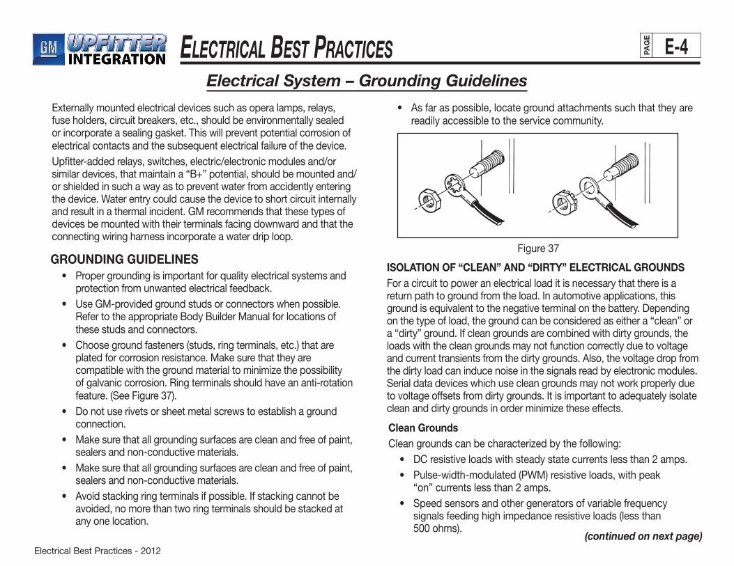
Electrical Best Practices - 2012
ElEctrical BEst PracticEs E-4PAG
E
Electrical System – Grounding Guidelines
(continued on next page)
Externally mounted electrical devices such as opera lamps, relays, fuse holders, circuit breakers, etc., should be environmentally sealed or incorporate a sealing gasket. This will prevent potential corrosion of electrical contacts and the subsequent electrical failure of the device.Upfitter-added relays, switches, electric/electronic modules and/or similar devices, that maintain a “B+” potential, should be mounted and/or shielded in such a way as to prevent water from accidently entering the device. Water entry could cause the device to short circuit internally and result in a thermal incident. GM recommends that these types of devices be mounted with their terminals facing downward and that the connecting wiring harness incorporate a water drip loop.
GROUNDING GUIDELINES • Propergroundingisimportantforqualityelectricalsystemsand
protection from unwanted electrical feedback. • UseGM-providedgroundstudsorconnectorswhenpossible.
Refer to the appropriate Body Builder Manual for locations of these studs and connectors.
• Choosegroundfasteners(studs,ringterminals,etc.)thatare plated for corrosion resistance. Make sure that they are compatiblewiththegroundmaterialtominimizethepossibilityof galvanic corrosion. Ring terminals should have an anti-rotation feature.(SeeFigure37).
• Donotuserivetsorsheetmetalscrewstoestablishagroundconnection.
• Makesurethatallgroundingsurfacesarecleanandfreeofpaint, sealers and non-conductive materials.
• Makesurethatallgroundingsurfacesarecleanandfreeofpaint, sealers and non-conductive materials.
• Avoidstackingringterminalsifpossible.Ifstackingcannotbeavoided, no more than two ring terminals should be stacked at any one location.
• Asfaraspossible,locategroundattachmentssuchthattheyarereadily accessible to the service community.
Figure 37
ISOLATION OF “CLEAN” AND “DIRTY” ELECTRICAL GROUNDSFor a circuit to power an electrical load it is necessary that there is a return path to ground from the load. In automotive applications, this ground is equivalent to the negative terminal on the battery. Depending on the type of load, the ground can be considered as either a “clean” or a “dirty” ground. If clean grounds are combined with dirty grounds, the loads with the clean grounds may not function correctly due to voltage and current transients from the dirty grounds. Also, the voltage drop from the dirty load can induce noise in the signals read by electronic modules. Serialdatadeviceswhichusecleangroundsmaynotworkproperlydueto voltage offsets from dirty grounds. It is important to adequately isolate cleananddirtygroundsinorderminimizetheseeffects.
Clean GroundsCleangroundscanbecharacterizedbythefollowing: • DCresistiveloadswithsteadystatecurrentslessthan2amps. • Pulse-width-modulated(PWM)resistiveloads,withpeak
“on” currents less than 2 amps. • Speedsensorsandothergeneratorsofvariablefrequency
signals feeding high impedance resistive loads (less than 500ohms).

Electrical Best Practices - 2012
ElEctrical BEst PracticEs E-5PAG
E
Electrical System – Grounding Guidelines (cont'd)
• DClamploads,withsteadystatecurrentslessthan1amp. • PWMlamploads,withpeak“on”currents<1amp
(not including inrush current). • Serialdatasignals.
Dirty Grounds
• Resistiveorlamploadsfallingoutsidethe“clean”boundariesdescribed above.
• Anyloadthathaseitheracapacitiveorinductivecomponentthat would cause either “turn-on” transients (inrush currents), or “turn-off” transients (voltage spikes).
• Motorloads(exceptforsmalldevicessuchasdisplay stepper motors).
• Solenoidloads.
WELD NUTS, WELD STUDS, SCREW/WASHERS AND TERMINALS USED FOR GROUNDINGWeld NutsAnM6x1unthreadedweldnutandM6x1x20hexheadthread-rolling screw with flat washer (Taptite™ or equivalent) is recommended for body electrical grounding. These components are ideal for the welding and assembly processes, and provide a reliable ground path. • Agoodweld(drawnArctype)ismadebetweenthefastener
and the base metal.
• Theconductivecontactareabetweenthethreadsoftheboltand the nut must be adequate.
• Thereisenoughjointclamploadinthejointtopreventloosening and loss of the conductive ground path.
Weld Studs
TheweldstudconsistsofanM6x1.0x21studwithanM-Pointcoated with a conductive hexavalent chrome-free finish. The nut is part of the stud assembly, eliminating masking the threads and base of the stud and nut to prevent being coated by paint. The weld stud also has an anti-rotation feature which prevents the terminal from turning when tightened. Use weld studs only when a weld nut cannot be used. The preferred grounding method is the weld nut.Washer • Thewashershouldhavenominalouterdiameterof17mm
and a minimum thickness of 2 mm. • Thewashermustbelocatedunderthescrew'shead.Ground TerminalAM6thread-formingboltwithanunthreadedweldnutandananti-rotation tab that fits into a hole in the sheet metal is the recommended ground terminal. This terminal should be able to withstand a 10 Nm dynamic torque without deforming the tab. A maximum of two terminals should be stacked in one location. The second terminal does not have a tab and should be located between the tabbed terminal and the body. If one wire is a larger gage than the other, the larger gage wire should be placed in the tabbed terminal.
Clean Grounds (cont'd) • Theproperweldschedulesmustbeused.
• Thegriplengthofthejointmustbeadequatetomaintainclampload integrity.
If a weld nut can not be used, a surface weld stud with a loose nut should be used. The following conditions may prevent the use of a weld nut: • Waterorexhaustmayintrudethroughthroughholes. • Panelbacksidehasnoclearancefortheweldnut. • Panelbacksidehasnoaccessfornutattachment.
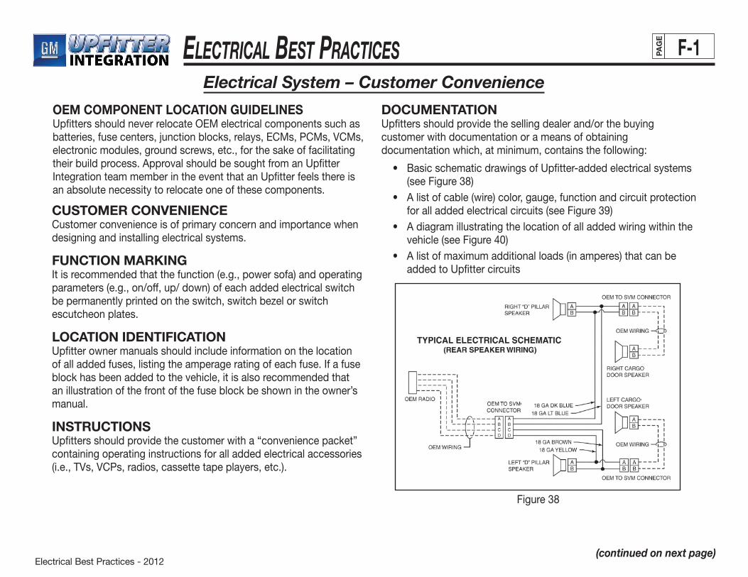
Electrical Best Practices - 2012
ElEctrical BEst PracticEs F-1PAG
E
Electrical System – Customer Convenience
(continued on next page)
OEM COMPONENT LOCATION GUIDELINESUpfitters should never relocate OEM electrical components such as batteries, fuse centers, junction blocks, relays, ECMs, PCMs, VCMs, electronic modules, ground screws, etc., for the sake of facilitatingtheir build process. Approval should be sought from an Upfitter Integration team member in the event that an Upfitter feels there is an absolute necessity to relocate one of these components.
CUSTOMER CONVENIENCECustomer convenience is of primary concern and importance when designing and installing electrical systems.
FUNCTION MARKINGIt is recommended that the function (e.g., power sofa) and operating parameters (e.g., on/off, up/ down) of each added electrical switch bepermanentlyprintedontheswitch,switchbezelorswitchescutcheon plates.
LOCATION IDENTIFICATIONUpfitter owner manuals should include information on the location of all added fuses, listing the amperage rating of each fuse. If a fuse block has been added to the vehicle, it is also recommended that an illustration of the front of the fuse block be shown in the owner’s manual.
INSTRUCTIONSUpfitters should provide the customer with a “convenience packet” containing operating instructions for all added electrical accessories (i.e., TVs, VCPs, radios, cassette tape players, etc.).
DOCUMENTATIONUpfitters should provide the selling dealer and/or the buying customer with documentation or a means of obtaining documentation which, at minimum, contains the following:
• BasicschematicdrawingsofUpfitter-addedelectricalsystems(seeFigure38)
• Alistofcable(wire)color,gauge,functionandcircuitprotectionfor all added electrical circuits (see Figure 39)
• Adiagramillustratingthelocationofalladdedwiringwithinthevehicle(seeFigure40)
• Alistofmaximumadditionalloads(inamperes)thatcanbeadded to Upfitter circuits
Figure38
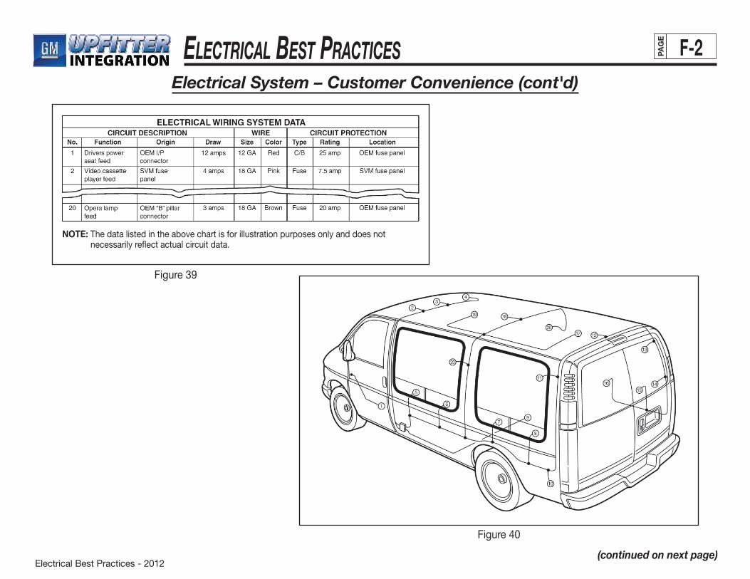
Electrical Best Practices - 2012
ElEctrical BEst PracticEs F-2PAG
E
Electrical System – Customer Convenience (cont'd)
(continued on next page)
Figure 39
Figure40
NOTE: The data listed in the above chart is for illustration purposes only and does not necessarily reflect actual circuit data.

Electrical Best Practices - 2012
ElEctrical BEst PracticEs G-1PAG
E
Electrical System – Headlamp/Foglamp Guidelines
HEADLAMP AIMINGThe Upfitter is responsible for aiming all headlamps on GM vehicles they convert prior to shipping the vehicle. Headlamps can be aimed using one of two methods:
• Mechanicalaimermethod
• Aimingscreenmethod
For headlamps incorporating both high and low beams in one combination lamp, aiming is required only for the low beams.
RefertotheapplicableGMServiceManualforspecificheadlamp aiming procedures.
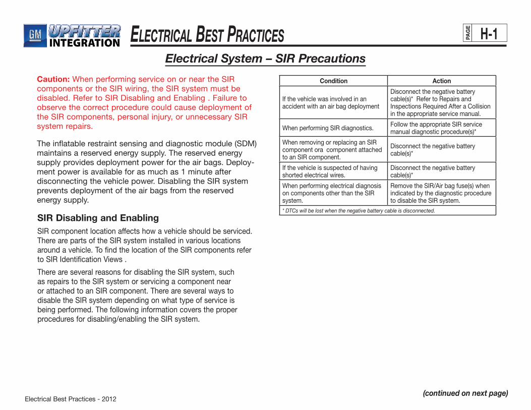
Electrical Best Practices - 2012
ElEctrical BEst PracticEs H-1PAG
E
(continued on next page)
Electrical System – SIR Precautions
Theinflatablerestraintsensinganddiagnosticmodule(SDM) maintains a reserved energy supply. The reserved energy supply provides deployment power for the air bags. Deploy-ment power is available for as much as 1 minute after disconnectingthevehiclepower.DisablingtheSIRsystemprevents deployment of the air bags from the reserved energy supply.
Caution: WhenperformingserviceonorneartheSIRcomponentsortheSIRwiring,theSIRsystemmustbedisabled.RefertoSIRDisablingandEnabling.Failuretoobserve the correct procedure could cause deployment of theSIRcomponents,personalinjury,orunnecessarySIRsystem repairs.
SIR Disabling and Enabling SIRcomponentlocationaffectshowavehicleshouldbeserviced.TherearepartsoftheSIRsysteminstalledinvariouslocationsaroundavehicle.TofindthelocationoftheSIRcomponentsreferto SIRIdentificationViews .
ThereareseveralreasonsfordisablingtheSIRsystem,suchasrepairstotheSIRsystemorservicingacomponentnearorattachedtoanSIRcomponent.ThereareseveralwaystodisabletheSIRsystemdependingonwhattypeofserviceisbeing performed. The following information covers the proper proceduresfordisabling/enablingtheSIRsystem.
Condition Action
If the vehicle was involved in an accident with an air bag deployment
Disconnect the negative battery cable(s)* Refer to Repairs and Inspections Required After a Collision in the appropriate service manual.
WhenperformingSIRdiagnostics. FollowtheappropriateSIRservicemanual diagnostic procedure(s)*
WhenremovingorreplacinganSIRcomponent ora component attached toanSIRcomponent.
Disconnect the negative battery cable(s)*
If the vehicle is suspected of having shorted electrical wires.
Disconnect the negative battery cable(s)*
When performing electrical diagnosis oncomponentsotherthantheSIRsystem.
RemovetheSIR/Airbagfuse(s)whenindicated by the diagnostic procedure todisabletheSIRsystem.
* DTCs will be lost when the negative battery cable is disconnected.
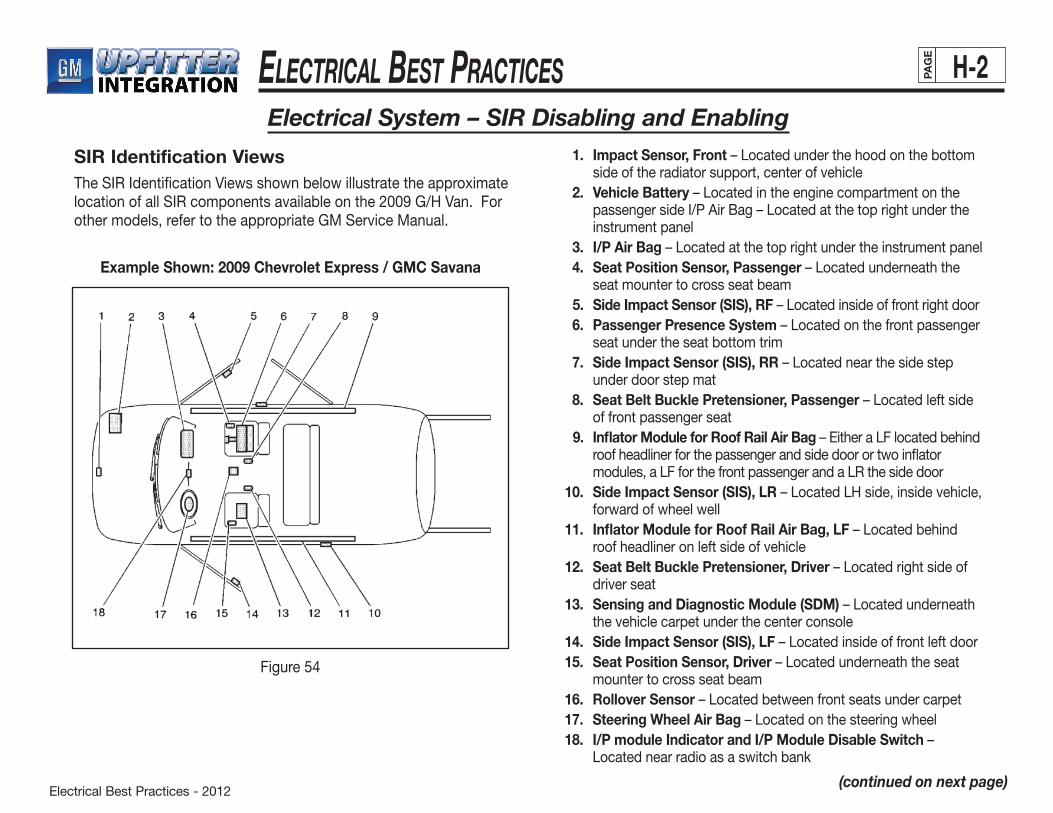
Electrical Best Practices - 2012
ElEctrical BEst PracticEs H-2PAG
E
Electrical System – SIR Disabling and Enabling
SIR Identification Views TheSIRIdentificationViewsshownbelowillustratetheapproximatelocationofallSIRcomponentsavailableonthe2009G/HVan.Forothermodels,refertotheappropriateGMServiceManual.
Example Shown: 2009 Chevrolet Express / GMC Savana
Figure54
1. Impact Sensor, Front–Locatedunderthehoodonthebottomside of the radiator support, center of vehicle
2. Vehicle Battery–LocatedintheenginecompartmentonthepassengersideI/PAirBag–Locatedatthetoprightundertheinstrument panel
3. I/P Air Bag–Locatedatthetoprightundertheinstrumentpanel 4. Seat Position Sensor, Passenger–Locatedunderneaththe
seat mounter to cross seat beam 5. Side Impact Sensor (SIS), RF–Locatedinsideoffrontrightdoor 6. Passenger Presence System–Locatedonthefrontpassenger
seat under the seat bottom trim 7. Side Impact Sensor (SIS), RR–Locatednearthesidestep
under door step mat 8. Seat Belt Buckle Pretensioner, Passenger–Locatedleftside
of front passenger seat 9. Inflator Module for Roof Rail Air Bag–EitheraLFlocatedbehind
roof headliner for the passenger and side door or two inflator modules,aLFforthefrontpassengerandaLRthesidedoor
10. Side Impact Sensor (SIS), LR–LocatedLHside,insidevehicle,forward of wheel well
11. Inflator Module for Roof Rail Air Bag, LF–Locatedbehindroof headliner on left side of vehicle
12. Seat Belt Buckle Pretensioner, Driver–Locatedrightsideofdriver seat
13. Sensing and Diagnostic Module (SDM)–Locatedunderneaththe vehicle carpet under the center console
14. Side Impact Sensor (SIS), LF–Locatedinsideoffrontleftdoor 15. Seat Position Sensor, Driver–Locatedunderneaththeseat
mounter to cross seat beam 16. Rollover Sensor–Locatedbetweenfrontseatsundercarpet 17. Steering Wheel Air Bag–Locatedonthesteeringwheel 18. I/P module Indicator and I/P Module Disable Switch –
Locatednearradioasaswitchbank
(continued on next page)
Electrical Best Practices - 2012
ElEctrical BEst PracticEs H-3PAG
E
(continued on next page)
Electrical System – SIR Disabling and Enabling (cont'd)
General Service Instructions The following are general service instructions which must be followed in order to properly repair the vehicle and return it to its original integrity: • Donotexposeinflatormodulestotemperatures
above65ºC(150ºF) • Verify the correct replacement part number.
Do not substitute a component from a different vehicle. • UseonlyoriginalGMreplacementpartsavailablefrom
yourauthorizedGMdealer.DonotusesalvagedpartsforrepairstotheSIRsystem.
Discard any of the following components if it has been dropped from a height of 91 cm (3 feet) or greater: • Inflatablerestraintsensinganddiagnosticmodule(SDM) • AnyInflatablerestraintairbagmodule • Inflatablerestraintsteeringwheelmodulecoil • AnyInflatablerestraintsensor • Inflatablerestraintseatbeltpretensioners • InflatablerestraintPassengerPresenceSystem(PPS)
module or sensor
Disabling Procedure - Air Bag Fuse 1. Turn the steering wheel so that the vehicles wheels are
pointing straight ahead.
2. Place the ignition in the OFF position.
3. Locateandremovethefuse(s)supplyingpowertothe SDM.RefertoSIRSchematicsorElectricalCenterIdentification Views in appropriate service manual.
4. Wait1minutebeforeworkingonthesystem.
Important:TheSDMmayhavemorethanonefusedpowerinput.ToensurethereisnounwantedSIRdeployment,personalinjury,orunnecessarySIRsystemrepairs,removeallfusessupplyingpowertotheSDM.WithallSDMfusesremovedandtheignitionswitchintheON position, the AIR BAG warning indicator illuminates. This is normal operation,anddoesnotindicateanSIRsystemmalfunction.
Enabling Procedure - Air Bag Fuse 1. Place the ignition in the OFF position. 2. Installthefuse(s)supplyingpowertotheSDM.Referto
SIRSchematicsorElectricalCenterIdentificationViewsinappropriate service manual.
3. Turn the ignition switch to the ON position. The AIR BAG indicator will flash then turn OFF.
4. PerformtheDiagnosticSystemCheck-VehicleiftheAIRBAGwarning indicator does not operate as described. Refer to DiagnosticSystemCheck-Vehicleinappropriateservicemanual.
Disabling Procedure - Negative Battery Cable 1. Turn the steering wheel so that the vehicles wheels are
pointing straight ahead. 2. Place the ignition in the OFF position. 3. Disconnect the negative battery cable from the battery. 4. Wait1minutebeforeworkingonsystem.
Enabling Procedure - Negative Battery Cable 1. Place the ignition in the OFF position. 2. Connect the negative battery cable to the battery. 3. Turn the ignition switch to the ON position. The AIR BAG
indicator will flash then turn OFF. 4. PerformtheDiagnosticSystemCheck-VehicleiftheAIRBAG warning indicator does not operate as described. Refer to Diag- nosticSystemCheck-Vehicleinappropriateservicemanual.
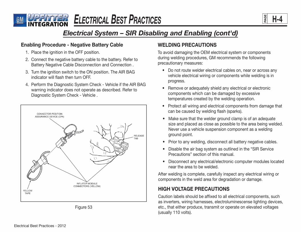
Electrical Best Practices - 2012
ElEctrical BEst PracticEs H-4PAG
E
Electrical System – SIR Disabling and Enabling (cont'd)
Enabling Procedure - Negative Battery Cable 1. Place the ignition in the OFF position.
2. Connect the negative battery cable to the battery. Refer to Battery Negative Cable Disconnection and Connection .
3. Turn the ignition switch to the ON position. The AIR BAG indicator will flash then turn OFF.
4. PerformtheDiagnosticSystemCheck-VehicleiftheAIRBAGwarning indicator does not operate as described. Refer to DiagnosticSystemCheck-Vehicle.
Figure53
WELDING PRECAUTIONSTo avoid damaging the OEM electrical system or components during welding procedures, GM recommends the following precautionary measures:
• Donotroutewelderelectricalcableson,nearoracrossanyvehicle electrical wiring or components while welding is in progress.
• Removeoradequatelyshieldanyelectricalorelectroniccomponents which can be damaged by excessive temperatures created by the welding operation.
• Protectallwiringandelectricalcomponentsfromdamagethatcan be caused by welding flash (sparks).
• Makesurethattheweldergroundclampisofanadequatesizeandplacedascloseaspossibletotheareabeingwelded.Never use a vehicle suspension component as a welding ground point.
• Priortoanywelding,disconnectallbatterynegativecables.
• Disabletheairbagsystemasoutlinedinthe“SIRServicePrecautions” section of this manual.
• Disconnectanyelectrical/electroniccomputermoduleslocatednear the area to be welded.
After welding is complete, carefully inspect any electrical wiring or components in the weld area for degradation or damage.
HIGH VOLTAGE PRECAUTIONSCaution labels should be affixed to all electrical components, such as inverters, wiring harnesses, electroluminescense lighting devices, etc., that either produce, transmit or operate on elevated voltages (usually 110 volts).

Electrical Best Practices - 2012
ElEctrical BEst PracticEs J-1PAG
E
Electrical System – Appendix I
GLOSSARY OF TERMS AND DEFINITIONSAccessible: Capable of being removed or exposed without damaging the vehicle or its finished interior or exterior surfaces.
Ampacity: The maximum current, expressed in amperes, that a conductor can carry on a continuous basis without exceeding the insulation’s temperature rating (ampere capacity).
Ampere: A unit of electrical current equivalent to a steady current produced by one volt applied across a resistance of one ohm.
ANSI:AmericanNationalStandardsInstitute
Approved: Acceptable to the “authority having jurisdiction.”
Automatic: A device that is self-acting, that operates by its own mechanism reacting to an outside stimulant such as application/loss of current, change in current strength, pressure, or mechanical configuration.
Auxiliary battery: A secondary device for the storage of low-voltage energy.
AWG: American Wire Gauge
Battery: A device for storage of low-voltage electrical energy.
Butt splice: A device used to join two wires together.
Cable:See“wire.”
Cable seal: A device to environmentally protect a connection system.
Cavities: The areas within a connector which hold the terminals. There is one cavity for each terminal in the connector.
Circuit: The complete path of electric current to and from its power source.
Circuit breaker: A device designed to open a circuit automatically on a predetermined overcurrent, without damage to itself, when properly applied within its rating.
Circuit segment: Any portion of a path of electric current for which a specific purpose or function exists.
CMA: Circular Mil Area
CMVSS:CanadianMotorVehicleSafetyStandards
Component: Any material, fixture, device, apparatus or similar item used in conjunction with, or that becomes part of, the completed electrical system installation.
Conductive: Capable of conducting electrical energy.
Conductor: Anything that provides a path for electric current.
Conduit: A tube or trough for protecting wires or cables.
Connection system: A group of parts the purpose of which is to make an electrical connection between wires or wire harness assemblies and is mechanically detachable.
Connector: A molded plastic device that houses one or more terminals and fastens or joins one or more conductors together and provides the mechanical connection in the connector system.
Connector seal: A device to environmentally protect a connection system.
Conversion vehicle: A vehicle that contains the permanent addition to, or modification of, any item or system from its original state as supplied by the original equipment manufacturer (OEM). This includes the addition of separate, fully independent systems that were not present in the vehicle as supplied by the OEM.
Conversion wiring system: Any wiring or wiring system installed or provided by the vehicle modifier.
(continued on next page)

Electrical Best Practices - 2012
ElEctrical BEst PracticEs J-2PAG
E
Converter: A modifier of an OEM vehicle.
Core: The conductive portion of a wire (usually copper).
Core wings: The part of a terminal which is crimped to the wire core to make an electrical connection between the wire and terminal.
CPA lock: Connector position assurance lock; a plastic tab that can be inserted through a hole in the inertia lock which provides a redundant connector locking device.
Dash panel: The partition that separates the engine compartment of a vehicle from the vehicle passenger compartment; sometimes referred to as the “firewall.”
Device: Any item of the electrical system, other than conductors orconnectors,thatcarriesorutilizeselectricalcurrenttoperformafunction.
ECM: Engine Control Module.
Equipment: Any material, device, appliance, fixture, etc., used as part of, or in connection with, the electrical system.
Exposed: Unprotected from inadvertent contact by another component, part or item.
FMVSS:FederalMotorVehicleSafetyStandards
Fuse: A specifically rated overcurrent protective device that incorporates a circuit-opening fusible part that is severed by the heat generated by the overcurrent passing through it.
Fuseblock: Two or more fuseholders sharing the same mounting base, but not necessarily the same power source.
Fuseholder: A device in which a single fuse is securely held, providing isolation of the source conductor from the distributing conductor.
GPT: General purpose thermoplastic; PVC insulated wire.
Electrical System – Appendix I
(continued on next page)
Grounded: A conducting connection between an electrical circuit or component and ground.
GXL: General purpose cross-linked (polyethylene insulated wire).
Harness: A grouping of electrical conductors provided with a means to maintain their grouping.
Incomplete vehicle: An assemblage consisting, as a minimum, of frame and chassis structure, powertrain, steering system, suspension system, and braking system, to the extent that those systems are to be part of the completed vehicle, that requires further manufacturing operations.
Indexing feature: Mechanical feature of a connector (usually a tab and slot) which allows connectors to be mated in only one way.
Inductive load: Any device (motors, magnetic solenoid, etc.) that utilizesaprocessbywhichelectricalenergyisusedtocreatemagnetic forces.
Inertia lock: The locking device on a connector that keeps connectors together once mated.
Insulated: Protected with a non-conductive coating.
Isolated circuitry: A wiring system with distribution and overcurrent protection totally separate and independent from the vehicle’s OEM wiring system.
Locking tang: Metal tab(s) on a terminal that locks the terminal in the connector cavity.
Low voltage:Anelectromotiveforcerated24volts,nominalorless,generally 12 volts in automotive applications.
OEM: Original Equipment Manufacturer; in this case, General Motors.
Ohm: A unit of electrical resistance equal to the resistance of a circuit in which a potential difference of one volt produces a current of one ampere.
Electrical Best Practices - 2012
ElEctrical BEst PracticEs J-3PAG
E
Open circuit: Condition by which electrical continuity is disrupted or broken in an electrical circuit.
Overcurrent: Any current that exceeds the rated current of equipment or ampacity of a conductor. Overcurrent may result from overload, short circuit or ground fault.
Overcurrent protection device: A device, such as a fuse or circuit breaker, designed to interrupt the circuit when the current flow exceeds a predetermined value.
Parasitic load: A small, continuous electrical draw on the battery.
PCM: Powertrain Control Module.
Pigtail: External conductors (wire leads) that originate within an electrical component or device.
Power source: The specific location or point that electrical current is obtained to supply the conversion wiring system.
Rating: Value that determines the current or voltage carrying capacity of a conductor or device.
Rating maximum: The point of highest current that a circuit breaker or fuse is intended to interrupt at under specified test conditions.
Ring terminal: Part used to connect wiring leads to threaded studs or directly to sheet metal. Also see “Terminal.”
RVIA: Recreation Vehicle Industry Association
SAE:SocietyofAutomotiveEngineers
Sealed: Closed or secured tightly for protection from environmental factors such as moisture or noxious fumes.
Secondary lock or TPA lock: Terminal position assurance lock; a separate or hinged part of a connector which prevents terminals from pulling out of the back of the connector.
Short circuit: A connection of comparatively low resistance accidentally or intentionally made between points in an electric circuit.
Electrical System – Appendix I (cont'd)SIR:SupplementalInflatableRestraint(airbagsystem).
Splice: A means of joining one or more conductors (wires).
Splice clip: A device used to facilitate splicing three or more wires.
Upfitter:SpecialVehicleManufacturer.Themanufacturerorconverter that installs additional equipment or modifies any item or system from its original state as supplied by the original equipment manufacturer (OEM).
Terminal: A metal device at the end of a wire or device which provides the electrical connection. Terminals are referred to as either male or female.
TPA lock: Terminal position assurance lock. Prevents a terminal from backing out of a connector. Thermally protected: A device provided with a means of protection that opens the circuit’s source of current when excessive heat is generated.
Unsealed: Not closed or secured for protection from environmental factors.
VCM: Vehicle Control Module.
Volt: A unit of electromotive force equal to a force that, when steadily applied to a conductor with a resistance of 1 ohm, produces a current of 1 ampere.
Waterproof: Constructed to prevent moisture from entering the enclosure under specified test conditions.
Weatherproof:See“Waterproof.”
Wire: An electronically conductive core material (usually made of copper) covered with a nonconductive insulating material. Also referred to as “lead” or “cable.”
Wire nut: A twist-on wiring connector/insulator not designed for automotive use.

Electrical Best Practices - 2012
ElEctrical BEst PracticEs K-1PAG
E
Electrical System – Appendix II – Connecting Terminology
(continued on next page)
CONNECTING TERMINOLOGY
Connection system: A group of parts the purpose of which is to make an electrical connection between wires or wiring harness assemblies and is mechanically detachable.
Wire: An electronically conductive core material (usually copper) covered with a non-conductive insulation. Also referred to as “lead” or “cable.”
Connector: A plastic molded part which houses one or more terminals and provides the mechanical connection in the connection system.
Figure54
Indexing feature: A mechanical feature of a connector (usually a tab and slot) which allows connectors to be mated in only one way.
Inertia lock: A locking device on a connector that keeps connectors together once mated.
Cavities: Areas within a connector which hold the terminals. There is one cavity for each terminal in the connector.
Terminal: Metal part attached (crimped) to the end of a wire which provides the electrical connection. Terminals are referred to as either “male” or “female.”
Figure55
Figure56
Core wings: A part of the terminal which is crimped to the wire core to make an electrical connection between the wire and the terminal.
Insulation wings: A part of the terminal which is crimped to the wire insulation to provide added retention strength, strain relief for the core crimp, and in a sealed system, to hold the cable seal.
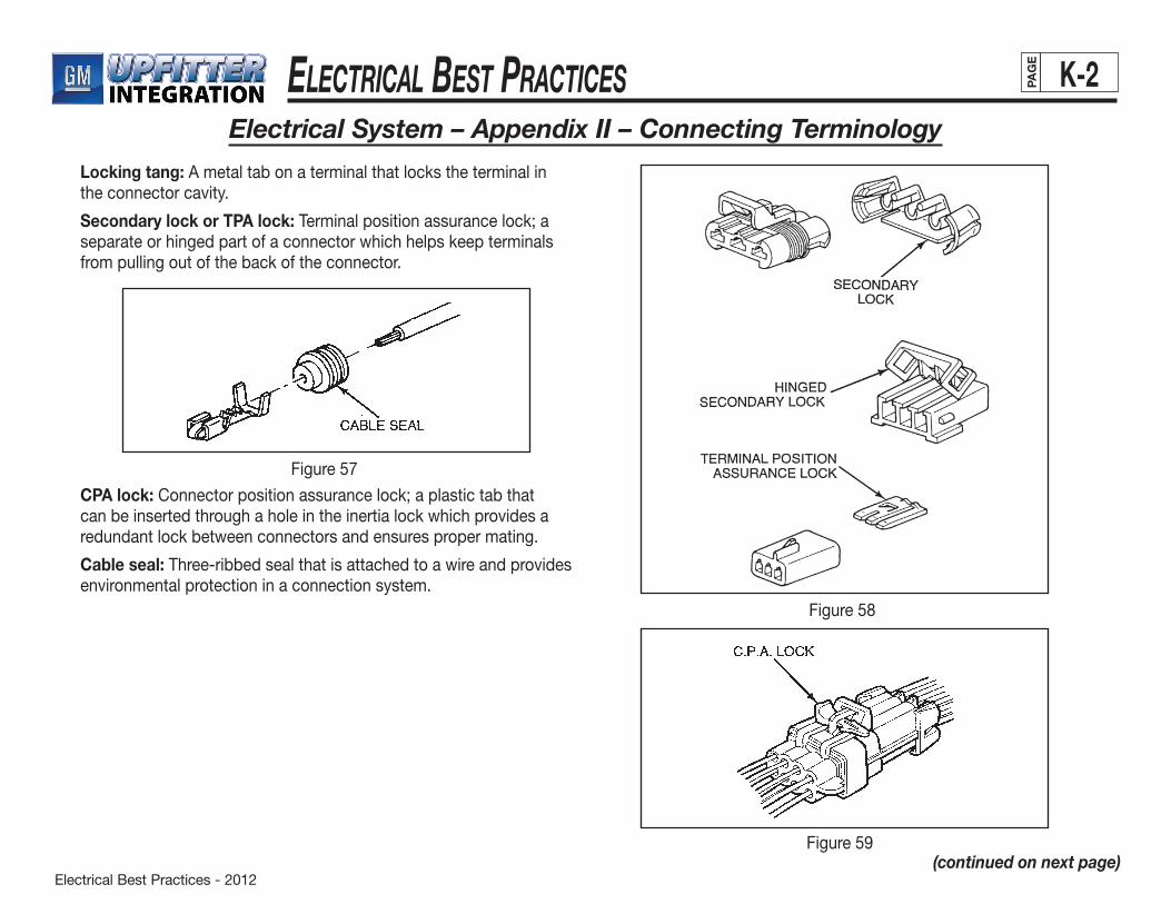
Electrical Best Practices - 2012
ElEctrical BEst PracticEs K-2PAG
E
Locking tang: A metal tab on a terminal that locks the terminal in the connector cavity.
Secondary lock or TPA lock: Terminal position assurance lock; a separate or hinged part of a connector which helps keep terminals from pulling out of the back of the connector.
Electrical System – Appendix II – Connecting Terminology
CPA lock: Connector position assurance lock; a plastic tab that can be inserted through a hole in the inertia lock which provides a redundant lock between connectors and ensures proper mating.
Cable seal: Three-ribbed seal that is attached to a wire and provides environmental protection in a connection system.
Figure57
Figure58
Figure59(continued on next page)
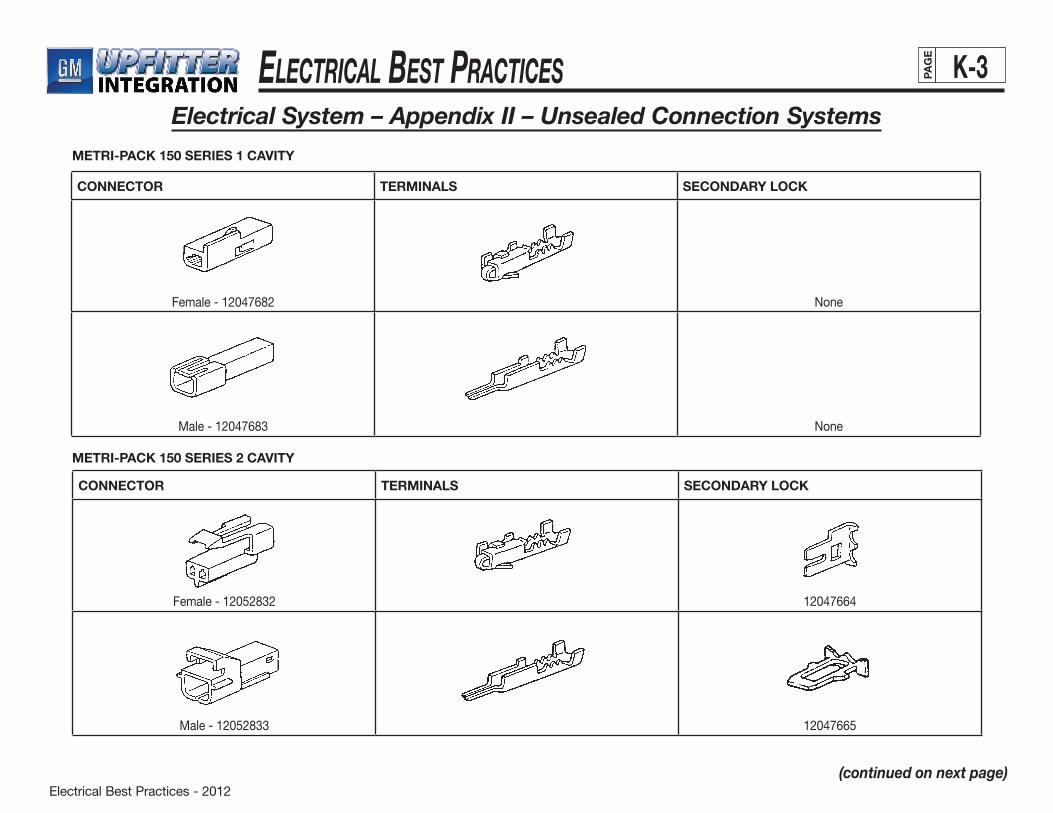
Electrical Best Practices - 2012
ElEctrical BEst PracticEs K-3PAG
E
Electrical System – Appendix II – Unsealed Connection Systems
CONNECTOR TERMINALS SECONDARY LOCK
Female-12047682 None
Male-12047683 None
CONNECTOR TERMINALS SECONDARY LOCK
Female-12052832 12047664
Male-12052833 12047665
METRI-PACK 150 SERIES 1 CAVITY
METRI-PACK 150 SERIES 2 CAVITY
(continued on next page)
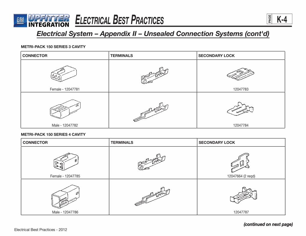
Electrical Best Practices - 2012
ElEctrical BEst PracticEs K-4PAG
E
(continued on next page)
Electrical System – Appendix II – Unsealed Connection Systems (cont'd)
(continued on next page)
CONNECTOR TERMINALS SECONDARY LOCK
Female-12047781 12047783
Male-12047782 12047784
CONNECTOR TERMINALS SECONDARY LOCK
Female-12047785 12047664(2reqd)
Male-12047786 12047787
METRI-PACK 150 SERIES 3 CAVITY
METRI-PACK 150 SERIES 4 CAVITY
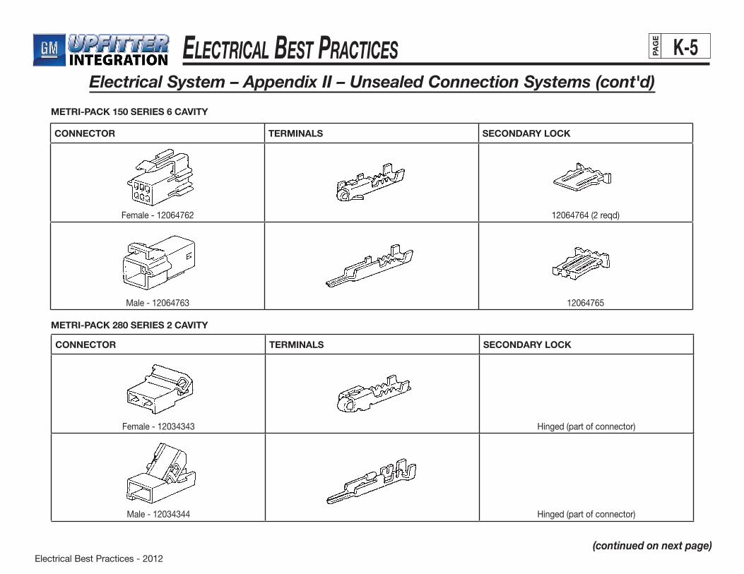
Electrical Best Practices - 2012
ElEctrical BEst PracticEs K-5PAG
E
Electrical System – Appendix II – Unsealed Connection Systems (cont'd)
(continued on next page)
CONNECTOR TERMINALS SECONDARY LOCK
Female-12064762 12064764(2reqd)
Male-12064763 12064765
CONNECTOR TERMINALS SECONDARY LOCK
Female-12034343 Hinged (part of connector)
Male-12034344 Hinged (part of connector)
METRI-PACK 150 SERIES 6 CAVITY
METRI-PACK 280 SERIES 2 CAVITY
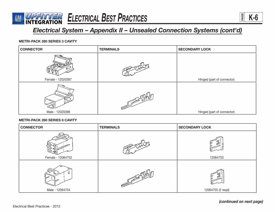
Electrical Best Practices - 2012
ElEctrical BEst PracticEs K-6PAG
E
Electrical System – Appendix II – Unsealed Connection Systems (cont'd)
(continued on next page)
CONNECTOR TERMINALS SECONDARY LOCK
Female - 12020397 Hinged (part of connector)
Male-12020398 Hinged (part of connector)
CONNECTOR TERMINALS SECONDARY LOCK
Female-12064752 12064753
Male-12064754 12064755(2reqd)
METRI-PACK 280 SERIES 3 CAVITY
METRI-PACK 280 SERIES 6 CAVITY
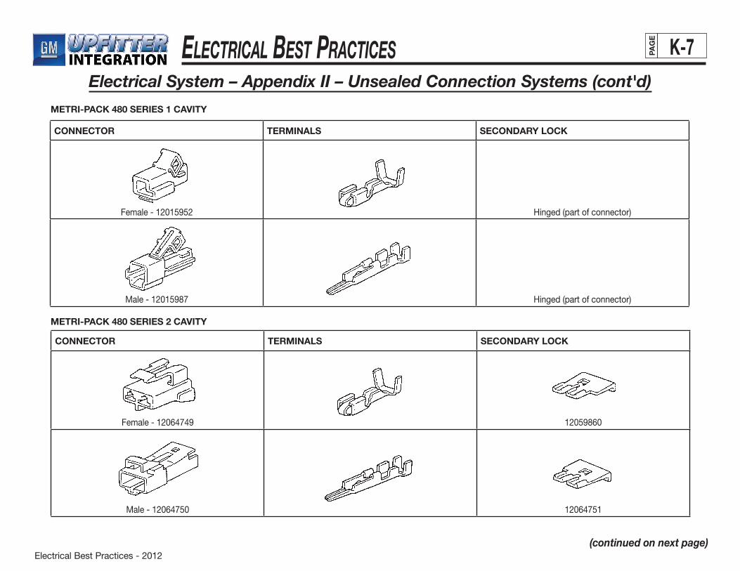
Electrical Best Practices - 2012
ElEctrical BEst PracticEs K-7PAG
E
Electrical System – Appendix II – Unsealed Connection Systems (cont'd)
(continued on next page)
CONNECTOR TERMINALS SECONDARY LOCK
Female-12015952 Hinged (part of connector)
Male-12015987 Hinged (part of connector)
CONNECTOR TERMINALS SECONDARY LOCK
Female-12064749 12059860
Male-12064750 12064751
METRI-PACK 480 SERIES 1 CAVITY
METRI-PACK 480 SERIES 2 CAVITY
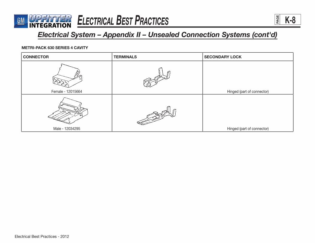
Electrical Best Practices - 2012
ElEctrical BEst PracticEs K-8PAG
E
Electrical System – Appendix II – Unsealed Connection Systems (cont'd)
CONNECTOR TERMINALS SECONDARY LOCK
Female-12015664 Hinged (part of connector)
Male-12034295 Hinged (part of connector)
METRI-PACK 630 SERIES 4 CAVITY

Electrical Best Practices - 2012
ElEctrical BEst PracticEs K-9PAG
E
Electrical System – Appendix II – Sealed Connection Systems
(continued on next page)
CONNECTOR TERMINALS SECONDARY LOCK CABLE SEALS
Female-12052641 12052634
Male-12162000 12052634
CONNECTOR TERMINALS SECONDARY LOCK CABLE SEALS
Female - 12110293 12052845
Male-12129615 12052845
METRI-PACK 150 SERIES 2 CAVITY
METRI-PACK 150 SERIES 3 CAVITY
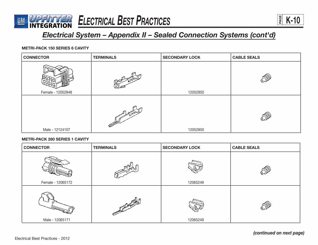
Electrical Best Practices - 2012
ElEctrical BEst PracticEs K-10PAG
E
Electrical System – Appendix II – Sealed Connection Systems (cont'd)
(continued on next page)
CONNECTOR TERMINALS SECONDARY LOCK CABLE SEALS
Female-12052848 12052850
Male-12124107 12052850
CONNECTOR TERMINALS SECONDARY LOCK CABLE SEALS
Female-12065172 12065249
Male-12065171 12065249
METRI-PACK 150 SERIES 6 CAVITY
METRI-PACK 280 SERIES 1 CAVITY
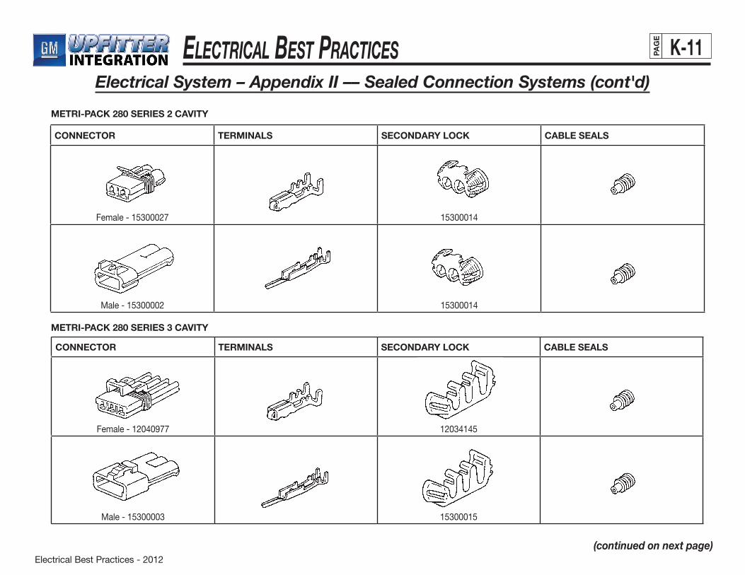
Electrical Best Practices - 2012
ElEctrical BEst PracticEs K-11PAG
E
Electrical System – Appendix II –– Sealed Connection Systems (cont'd)
(continued on next page)
CONNECTOR TERMINALS SECONDARY LOCK CABLE SEALS
Female-15300027 15300014
Male-15300002 15300014
CONNECTOR TERMINALS SECONDARY LOCK CABLE SEALS
Female-12040977 12034145
Male-15300003 15300015
METRI-PACK 280 SERIES 2 CAVITY
METRI-PACK 280 SERIES 3 CAVITY

Electrical Best Practices - 2012
ElEctrical BEst PracticEs K-12PAG
E
Electrical System – Appendix II – Sealed Connection Systems (cont'd)
CONNECTOR TERMINALS SECONDARY LOCK CABLE SEALS
Female-15300027 15300014
Male-15300002 15300014
METRI-PACK 630 SERIES 3 CAVITY
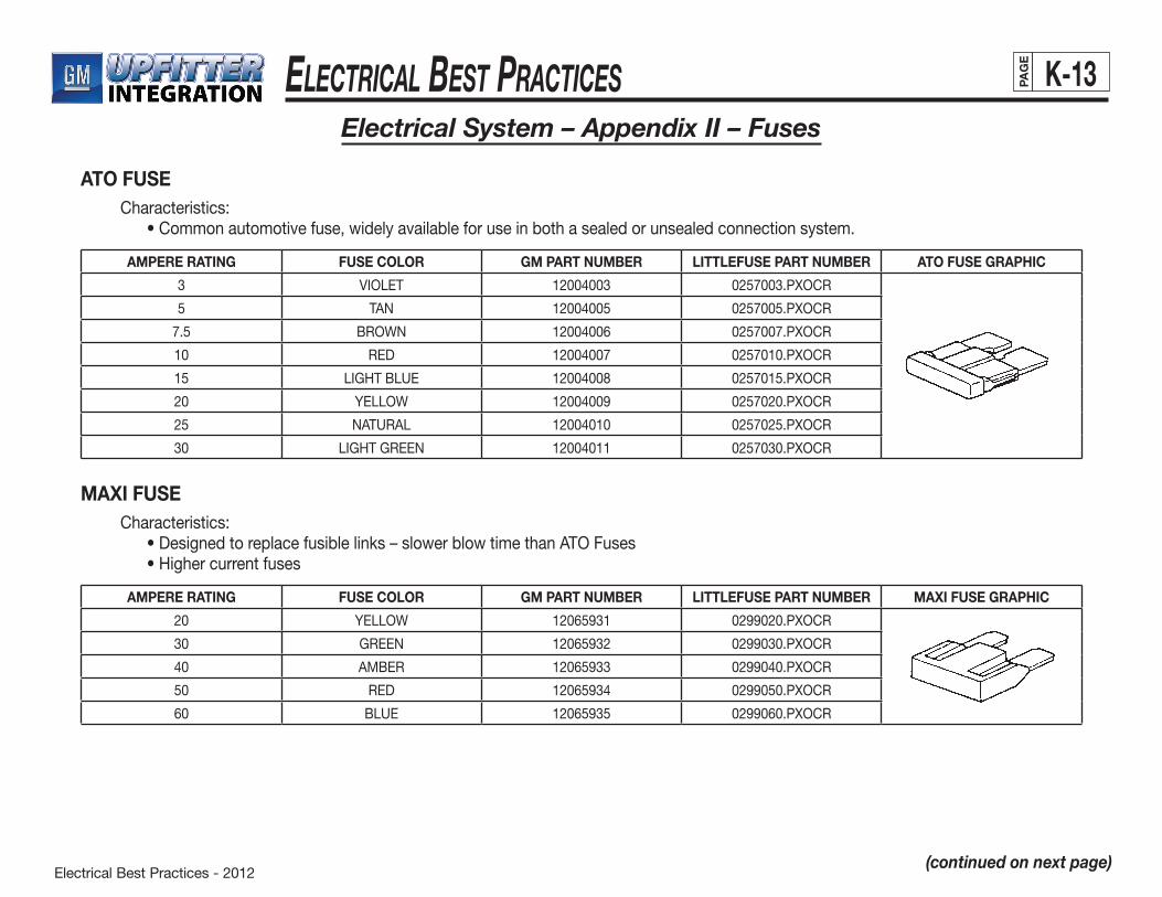
Electrical Best Practices - 2012
ElEctrical BEst PracticEs K-13PAG
E
Electrical System – Appendix II – Fuses
ATO FUSE Characteristics: •Commonautomotivefuse,widelyavailableforuseinbothasealedorunsealedconnectionsystem.
MAXI FUSE Characteristics: •Designedtoreplacefusiblelinks–slowerblowtimethanATOFuses •Highercurrentfuses
AMPERE RATING FUSE COLOR GM PART NUMBER LITTLEFUSE PART NUMBER ATO FUSE GRAPHIC
3 VIOLET 12004003 0257003.PXOCR
5 TAN 12004005 0257005.PXOCR
7.5 BROWN 12004006 0257007.PXOCR
10 RED 12004007 0257010.PXOCR
15 LIGHTBLUE 12004008 0257015.PXOCR
20 YELLOW 12004009 0257020.PXOCR
25 NATURAL 12004010 0257025.PXOCR
30 LIGHTGREEN 12004011 0257030.PXOCR
AMPERE RATING FUSE COLOR GM PART NUMBER LITTLEFUSE PART NUMBER MAXI FUSE GRAPHIC
20 YELLOW 12065931 0299020.PXOCR
30 GREEN 12065932 0299030.PXOCR
40 AMBER 12065933 0299040.PXOCR
50 RED 12065934 0299050.PXOCR
60 BLUE 12065935 0299060.PXOCR
(continued on next page)
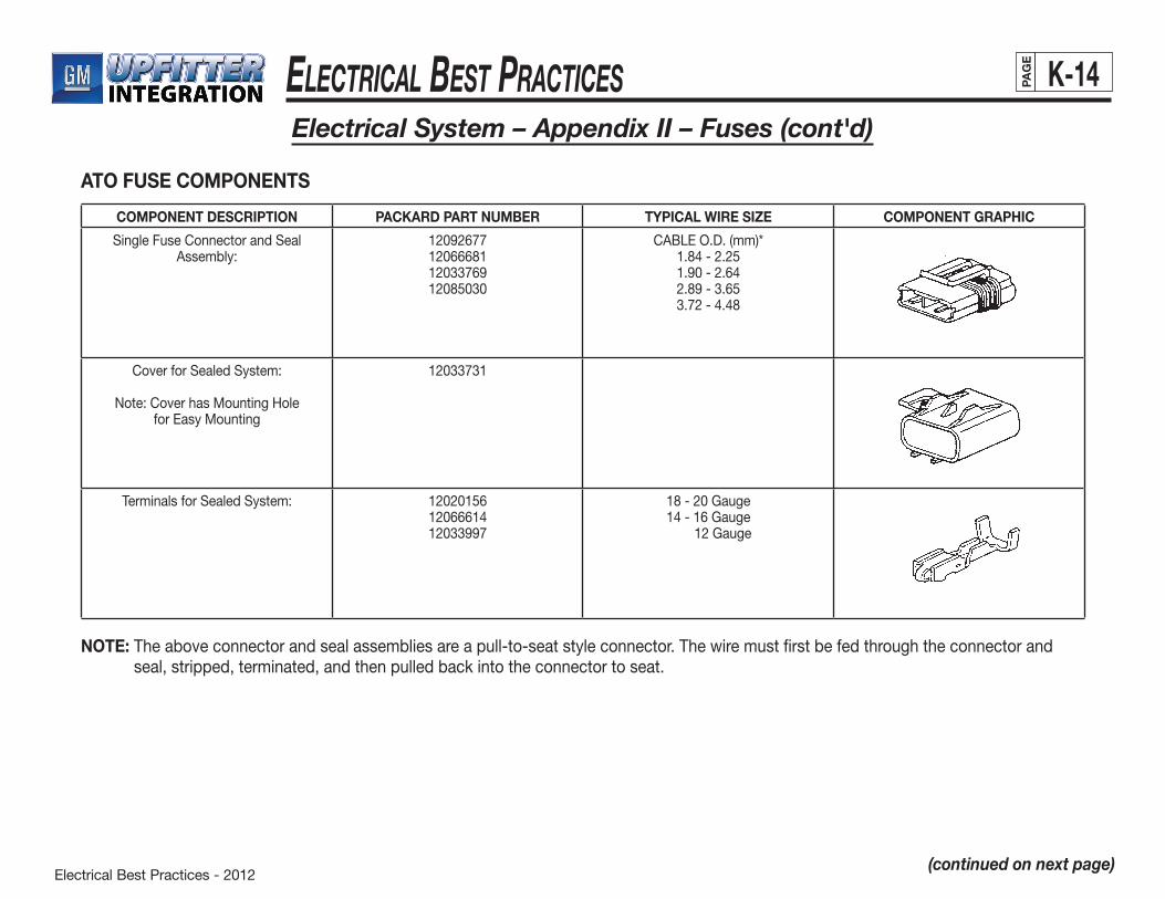
Electrical Best Practices - 2012
ElEctrical BEst PracticEs K-14PAG
E
Electrical System – Appendix II – Fuses (cont'd)
ATO FUSE COMPONENTS
(continued on next page)
NOTE: The above connector and seal assemblies are a pull-to-seat style connector. The wire must first be fed through the connector and seal, stripped, terminated, and then pulled back into the connector to seat.
COMPONENT DESCRIPTION PACKARD PART NUMBER TYPICAL WIRE SIZE COMPONENT GRAPHIC
SingleFuseConnectorandSealAssembly:
12092677120666811203376912085030
CABLEO.D.(mm)*1.84-2.251.90-2.642.89-3.653.72-4.48
CoverforSealedSystem:
Note: Cover has Mounting Holefor Easy Mounting
12033731
TerminalsforSealedSystem: 120201561206661412033997
18-20Gauge14-16Gauge 12 Gauge
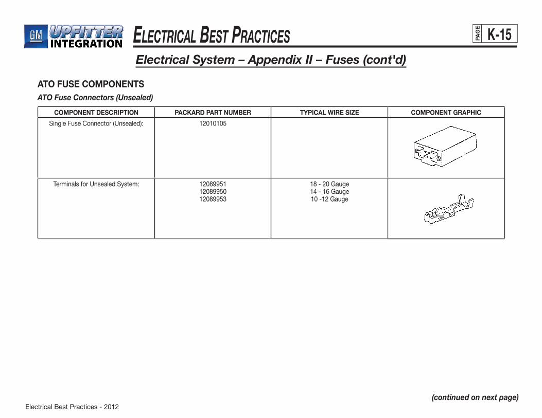
Electrical Best Practices - 2012
ElEctrical BEst PracticEs K-15PAG
E
Electrical System – Appendix II – Fuses (cont'd)
ATO FUSE COMPONENTSATO Fuse Connectors (Unsealed)
(continued on next page)
COMPONENT DESCRIPTION PACKARD PART NUMBER TYPICAL WIRE SIZE COMPONENT GRAPHIC
SingleFuseConnector(Unsealed): 12010105
TerminalsforUnsealedSystem: 120899511208995012089953
18-20Gauge14-16Gauge10 -12 Gauge
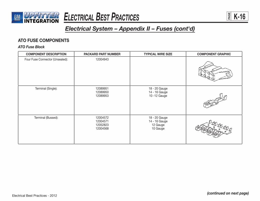
Electrical Best Practices - 2012
ElEctrical BEst PracticEs K-16PAG
E
Electrical System – Appendix II – Fuses (cont'd)
ATO FUSE COMPONENTSATO Fuse Block
(continued on next page)
COMPONENT DESCRIPTION PACKARD PART NUMBER TYPICAL WIRE SIZE COMPONENT GRAPHIC
Four Fuse Connector (Unsealed): 12004943
Terminal(Single): 120899511208995012089953
18-20Gauge14-16Gauge10 -12 Gauge
Terminal (Bussed): 12004572120045711205282312004568
18-20Gauge14-16Gauge
12 Gauge10 Gauge
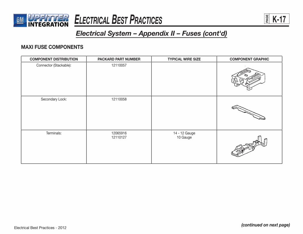
Electrical Best Practices - 2012
ElEctrical BEst PracticEs K-17PAG
E
Electrical System – Appendix II – Fuses (cont'd)
MAXI FUSE COMPONENTS
(continued on next page)
COMPONENT DISTRIBUTION PACKARD PART NUMBER TYPICAL WIRE SIZE COMPONENT GRAPHIC
Connector(Stackable): 12110057
SecondaryLock: 12110058
Terminals: 1206591612110127
14-12Gauge10 Gauge
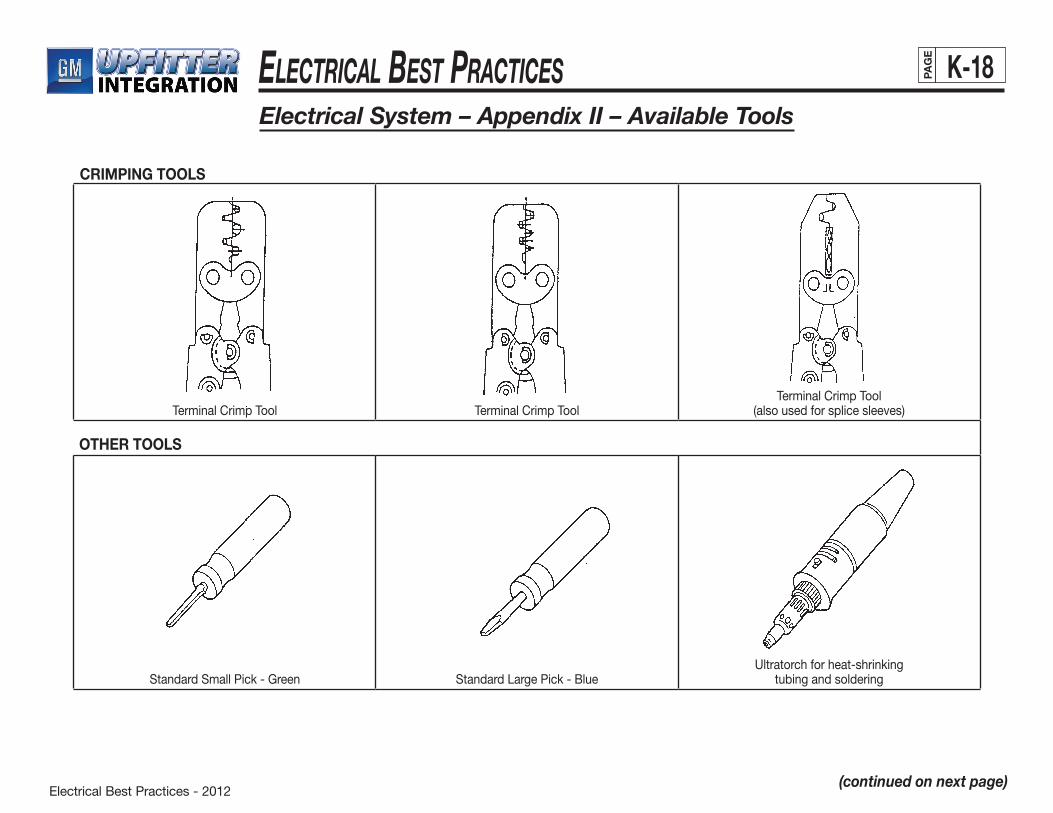
Electrical Best Practices - 2012
ElEctrical BEst PracticEs K-18PAG
E
Electrical System – Appendix II – Available Tools
(continued on next page)
Terminal Crimp Tool Terminal Crimp ToolTerminal Crimp Tool
(also used for splice sleeves)
OTHER TOOLS
StandardSmallPick-Green StandardLargePick-BlueUltratorch for heat-shrinking
tubing and soldering
CRIMPING TOOLS
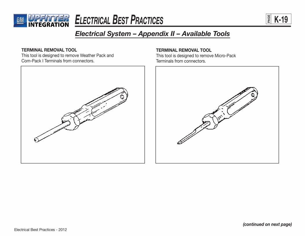
Electrical Best Practices - 2012
ElEctrical BEst PracticEs K-19PAG
E
Electrical System – Appendix II – Available Tools
(continued on next page)
TERMINAL REMOVAL TOOLThis tool is designed to remove Weather Pack and Com-Pack I Terminals from connectors.
TERMINAL REMOVAL TOOL This tool is designed to remove Micro-Pack Terminals from connectors.
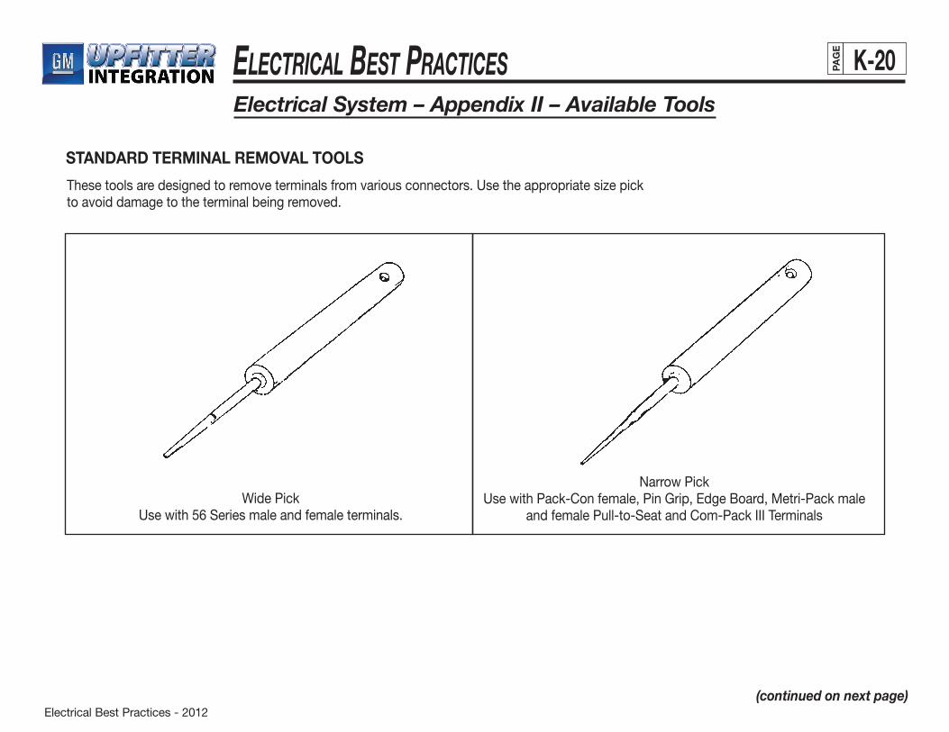
Electrical Best Practices - 2012
ElEctrical BEst PracticEs K-20PAG
E
Electrical System – Appendix II – Available Tools
(continued on next page)
STANDARD TERMINAL REMOVAL TOOLS
Thesetoolsaredesignedtoremoveterminalsfromvariousconnectors.Usetheappropriatesizepick to avoid damage to the terminal being removed.
Wide PickUsewith56Seriesmaleandfemaleterminals.
Narrow PickUse with Pack-Con female, Pin Grip, Edge Board, Metri-Pack male
andfemalePull-to-SeatandCom-PackIIITerminals
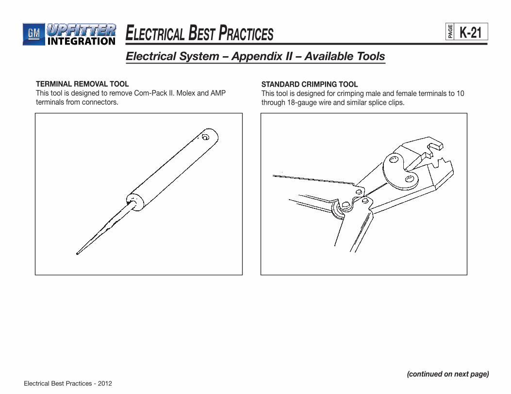
Electrical Best Practices - 2012
ElEctrical BEst PracticEs K-21PAG
E
Electrical System – Appendix II – Available Tools
(continued on next page)
TERMINAL REMOVAL TOOLThis tool is designed to remove Com-Pack II. Molex and AMP terminals from connectors.
STANDARD CRIMPING TOOLThis tool is designed for crimping male and female terminals to 10 through18-gaugewireandsimilarspliceclips.
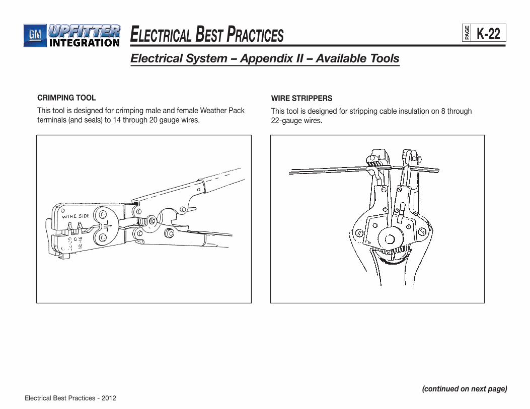
Electrical Best Practices - 2012
ElEctrical BEst PracticEs K-22PAG
E
Electrical System – Appendix II – Available Tools
(continued on next page)
CRIMPING TOOL
This tool is designed for crimping male and female Weather Pack terminals(andseals)to14through20gaugewires.
WIRE STRIPPERS
Thistoolisdesignedforstrippingcableinsulationon8through22-gauge wires.
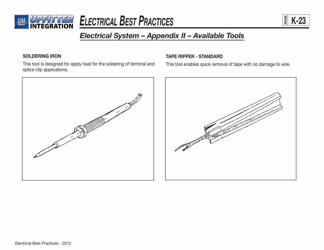
Electrical Best Practices - 2012
ElEctrical BEst PracticEs K-23PAG
E
Electrical System – Appendix II – Available Tools
SOLDERING IRON
This tool is designed for apply heat for the soldering of terminal and splice clip applications.
TAPE RIPPER - STANDARD
This tool enables quick removal of tape with no damage to wire.
Paint & Sealing – Best Practices – 2012
Paint & Sealing – BeSt PracticeS iPAG
E
PAINT AND SEALING ������������������������������������������������������������������������������������������������������������������������������������������������������������������������������������ 1 Sealants �������������������������������������������������������������������������������������������������������������������������������������������������������������������������������������������������� 1 Bonding Principles ���������������������������������������������������������������������������������������������������������������������������������������������������������������������������������� 1 Reactive and Non-Reactive Sealants ����������������������������������������������������������������������������������������������������������������������������������������������������� 1 Solvent Type Sealants ���������������������������������������������������������������������������������������������������������������������������������������������������������������������������� 2 GM Specifications ���������������������������������������������������������������������������������������������������������������������������������������������������������������������������������� 2 Surface Preparation �������������������������������������������������������������������������������������������������������������������������������������������������������������������������������� 2 Paint �������������������������������������������������������������������������������������������������������������������������������������������������������������������������������������������������������� 2 Standards ������������������������������������������������������������������������������������������������������������������������������������������������������������������������������������������������ 2 SURFACE APPEARANCE ����������������������������������������������������������������������������������������������������������������������������������������������������������������������������� 4 Paint Audit Procedure ����������������������������������������������������������������������������������������������������������������������������������������������������������������������������� 4 Quality Requirements For Appearance Attributes ��������������������������������������������������������������������������������������������������������������������������������� 4 Distinctiveness Of Image (DOI) ��������������������������������������������������������������������������������������������������������������������������������������������������������������� 4 Table 1 – Appearance Zones ���������������������������������������������������������������������������������������������������������������������������������������������������������� 4 Table 2 – Distinctiveness of Image (DOI) ��������������������������������������������������������������������������������������������������������������������������������������� 5 Gloss ������������������������������������������������������������������������������������������������������������������������������������������������������������������������������������������������������� 5 Table 3 – Gloss ������������������������������������������������������������������������������������������������������������������������������������������������������������������������������� 5 Orange Peel �������������������������������������������������������������������������������������������������������������������������������������������������������������������������������������������� 5 Table 4 – Orange Peel �������������������������������������������������������������������������������������������������������������������������������������������������������������������� 5 Uniformity ������������������������������������������������������������������������������������������������������������������������������������������������������������������������������������������������ 5 Mottle ������������������������������������������������������������������������������������������������������������������������������������������������������������������������������������������������������ 6 Table 5 – Mottle ������������������������������������������������������������������������������������������������������������������������������������������������������������������������������ 6 PAINT SURFACE BLEMISHES ��������������������������������������������������������������������������������������������������������������������������������������������������������������������� 7 Paint Chips���������������������������������������������������������������������������������������������������������������������������������������������������������������������������������������������� 7 Craters ���������������������������������������������������������������������������������������������������������������������������������������������������������������������������������������������������� 7
Index
(continued on next page)
Paint & Sealing – Best Practices – 2012
Paint & Sealing – BeSt PracticeS iiPAG
E
Index (cont'd)Paint Surface Blemishes (continued) Dirt ����������������������������������������������������������������������������������������������������������������������������������������������������������������������������������������������������������� 7 Table 6 – Paint Chips ���������������������������������������������������������������������������������������������������������������������������������������������������������������������� 7 Table 7 – Craters����������������������������������������������������������������������������������������������������������������������������������������������������������������������������� 7 Table 8 – Dirt (In Paint) ������������������������������������������������������������������������������������������������������������������������������������������������������������������� 7 Dings ������������������������������������������������������������������������������������������������������������������������������������������������������������������������������������������������������� 8 Overspray ������������������������������������������������������������������������������������������������������������������������������������������������������������������������������������������������ 8 Pinholes/Popping ������������������������������������������������������������������������������������������������������������������������������������������������������������������������������������ 8 Polish Marks ������������������������������������������������������������������������������������������������������������������������������������������������������������������������������������������� 8 Table 9 – Dings ������������������������������������������������������������������������������������������������������������������������������������������������������������������������������� 8 Table 10 – Overspray ���������������������������������������������������������������������������������������������������������������������������������������������������������������������� 8 Table 11 – Pinholes/Popping ���������������������������������������������������������������������������������������������������������������������������������������������������������� 8 Sags and Runs ��������������������������������������������������������������������������������������������������������������������������������������������������������������������������������������� 9 Table 12 – Sags and Runs�������������������������������������������������������������������������������������������������������������������������������������������������������������� 9 PAINTED BODY APPEARANCE ����������������������������������������������������������������������������������������������������������������������������������������������������������������� 10 Sand Scratches ������������������������������������������������������������������������������������������������������������������������������������������������������������������������������������ 10 Scratches ���������������������������������������������������������������������������������������������������������������������������������������������������������������������������������������������� 10 Water Spots ������������������������������������������������������������������������������������������������������������������������������������������������������������������������������������������ 10 Table 13 – Sand Scratches ���������������������������������������������������������������������������������������������������������������������������������������������������������� 10 Table 14 – Scratches After Paint �������������������������������������������������������������������������������������������������������������������������������������������������� 10 Table 15 – Water Spots ���������������������������������������������������������������������������������������������������������������������������������������������������������������� 10 Wet Mars ����������������������������������������������������������������������������������������������������������������������������������������������������������������������������������������������� 11 Bullseyes ����������������������������������������������������������������������������������������������������������������������������������������������������������������������������������������������� 11 Table 16 – Wet Mars ��������������������������������������������������������������������������������������������������������������������������������������������������������������������� 11 Table 17 – Bullseyes ��������������������������������������������������������������������������������������������������������������������������������������������������������������������� 11
Paint & Sealing – Best Practices – 2012
Paint & Sealing – BeSt PracticeS iiiPAG
E
Index (cont'd)APPEARANCE ZONES �������������������������������������������������������������������������������������������������������������������������������������������������������������������������������� 12 Table 18 – Appearance Zones Pick-Up Trucks-Utility-Suburban-Vans-APV �������������������������������������������������������������������������������������� 12 Preparation �������������������������������������������������������������������������������������������������������������������������������������������������������������������������������������������� 17 Painted Surfaces �������������������������������������������������������������������������������������������������������������������������������������������������������������������������� 17 Unpainted Surfaces ���������������������������������������������������������������������������������������������������������������������������������������������������������������������� 17PAINT SYSTEMS AND PROCEDURES ������������������������������������������������������������������������������������������������������������������������������������������������������ 18 GM-Approved Refinish Materials ��������������������������������������������������������������������������������������������������������������������������������������������������������� 18 The Bottom Line ��������������������������������������������������������������������������������������������������������������������������������������������������������������������������� 18 Undercoats ������������������������������������������������������������������������������������������������������������������������������������������������������������������������������������������� 18 Prepcoats (Etch Primers) �������������������������������������������������������������������������������������������������������������������������������������������������������������� 19 Primer-Surfacers ��������������������������������������������������������������������������������������������������������������������������������������������������������������������������� 19 Primer-Sealers ������������������������������������������������������������������������������������������������������������������������������������������������������������������������������ 19 Sealers (Adhesion Promoters) ������������������������������������������������������������������������������������������������������������������������������������������������������ 19 Putties and Fillers ��������������������������������������������������������������������������������������������������������������������������������������������������������������������������������� 20 Topcoat ������������������������������������������������������������������������������������������������������������������������������������������������������������������������������������������������� 20 Basecoat ����������������������������������������������������������������������������������������������������������������������������������������������������������������������������������������������� 20 Clearcoat ����������������������������������������������������������������������������������������������������������������������������������������������������������������������������������������������� 20 Finesse/Clear and Polish ���������������������������������������������������������������������������������������������������������������������������������������������������������������������� 20 Sanding (Primer) ����������������������������������������������������������������������������������������������������������������������������������������������������������������������������������� 20 Moist Sanding ��������������������������������������������������������������������������������������������������������������������������������������������������������������������������������������� 20 Wet Sanding ������������������������������������������������������������������������������������������������������������������������������������������������������������������������������������������ 21 Ionizers �������������������������������������������������������������������������������������������������������������������������������������������������������������������������������������������������� 21
(continued on next page)

Paint & Sealing – Best Practices – 2012
ivPAG
E
Index (cont'd)REPAIR SYSTEMS ....................................................................................................................................................................................... 22 Sanding ................................................................................................................................................................................................. 22 Repair Primer (Etch) .............................................................................................................................................................................. 22 Spot Repair ........................................................................................................................................................................................... 23 Sanding ......................................................................................................................................................................................... 23 Repair Primer ................................................................................................................................................................................ 23 Color Coat .................................................................................................................................................................................... 23 Touch-Up Repair ................................................................................................................................................................................... 23 Spot Finesse Sanding/Polishing Basecoat .......................................................................................................................................... 24 Clearcoat ...................................................................................................................................................................................... 24 Removing Defects ........................................................................................................................................................................ 24 Sanding ......................................................................................................................................................................................... 24 Finesse Polish (Rotary) ................................................................................................................................................................. 25 Final Buffing (Orbital) .................................................................................................................................................................... 25 MANUAL SPRAY GUNS AND APPLICATIONS ......................................................................................................................................... 26 Table 19 – Table of Parameters/Trends in Movement .......................................................................................................................... 28 Solvent Rub Testing of Coats ............................................................................................................................................................... 29 Solvent Wipe Procedure ............................................................................................................................................................... 29 Table 20 – Solvent Rub Test Ratings ........................................................................................................................................... 29
Transit Coating ............................................................................................................................................................................................. 30 Properties ..................................................................................................................................................................................................... 30
APPENDIX I .................................................................................................................................................................................................. 30
Transit Coating Application Matrix ................................................................................................................................................................ 31 Fluid Delivery Rate ................................................................................................................................................................................ 32 Atomizing Air Pressure ......................................................................................................................................................................... 33 Dilution .................................................................................................................................................................................................. 34 Gun Distance ........................................................................................................................................................................................ 35
PAINT & SEALING – BEST PRACTICES
Paint & Sealing – Best Practices – 2012
Paint & Sealing – BeSt PracticeS vPAG
E
Appendix I (continued) Relative Gun Tip Speed (Conveyor Speed)������������������������������������������������������������������������������������������������������������������������������������������ 36 Ambient Air Temperature ���������������������������������������������������������������������������������������������������������������������������������������������������������������������� 37 Relative Humidity ���������������������������������������������������������������������������������������������������������������������������������������������������������������������������������� 38 Maintenance and Cleaning ����������������������������������������������������������������������������������������������������������������������������������������������������������� 39 Lubrication of Gun Parts ���������������������������������������������������������������������������������������������������������������������������������������������������������������������� 39 General Spray Gun Assembly �������������������������������������������������������������������������������������������������������������������������������������������������������������� 40 Air Adjustment Valve �������������������������������������������������������������������������������������������������������������������������������������������������������������������� 40 Fluid Adjustment Valve ����������������������������������������������������������������������������������������������������������������������������������������������������������������� 40 APPENDIX II ������������������������������������������������������������������������������������������������������������������������������������������������������������������������������������������������� 41 APPENDIX III ������������������������������������������������������������������������������������������������������������������������������������������������������������������������������������������������ 44
Paint & Sealing – Best Practices – 2012
Paint & Sealing – BeSt PracticeS 1PAG
E
Paints And Sealing
SealantsA sealant is any organic material used to prevent air, dust, water or noise from entering the vehicle body. They come in a variety of forms, including:
• bulk pumpable
• thumbgrade
• extruded
• die-cut parts
A sealant’s most important property is its bond strength; that is, its ability to adhere to the base material or “substrate” to which it is applied.
Sealant beads and their substrates are in constant molecular motion. This motion is the interplay of many forces of various magnitudes being applied from many directions. These forces may occur together or in any combination.
Sealants are primarily used on joints. The purpose of a joint is to carry a load or to transmit a load from one structural member to another. The point at which the load is transferred is called a joint.
Bonding PrinciplesThe following general principles provide a clearer picture of how sealants work:
• In order for effective bonding to occur, a sealant must be applied to a solid base material. Attempting to bond to a weak substrate will result in failure between the layers. Loose rust, for example, is a weak substrate.
• Directly related to bond quality is the degree of molecular contact between the sealer and substrate. Wetting and diffusion of the sealer causes this contact. If wetting
(continued on next page)
does not take place during application and curing, basic adhesion will not result.
• A variety of stresses (e.g. residual internal; thermal expansion and contraction; volumetric shrinkage or expansion; and environmental) act on the strength of a bond. Environmental stress, such as those produced by moisture or thermal cycling, have the greatest detrimental effects.
• Some common causes of poor bond formation are careless application, void in bond line, improper surface preparation, improper care and poor joint design.
Primers sometimes act as adhesion promoters. For example, where wetting is inadequate, the primer may act as a wetting medium to the substrate. This enables the sealer to easily wet the substrate, transforming a poor bond to satisfactory. Primers may also work as a barrier, preventing environmental factors such as water or gases from [displacing] the sealer at bonding sites.
Reactive And Non-Reactive SealantsThere are two basic types of sealants: reactive or non-reactive.
• Reactive sealants actually undergo a change to their basic molecular structure during bonding. That is, they react chemically to such processes as oxidation or polymerization to form a bond.
• Non-reactive sealants develop their final form and properties by solvent evaporation or fusion of compatible components. They do not undergo any chemical changes; only changes to their physical form.

Paint & Sealing – Best Practices – 2012
Paint & Sealing – BeSt PracticeS 2PAG
E
Paints And Sealing (cont'd)
(continued on next page)
Solvent Type SealantsSolvent type sealants have two distinct advantages:
• They have a quick set-up time.
• They can be used at ambient temperatures.
One disadvantage, however, is that they tend to shrink as the solvent evaporates. This shrinkage may leave voids in the seal. A typical solvent-type material is General Motors specification 9981111 sealer, air dry, repair.
Air-dry sealants are designed to cure without baking. They are solvent-containing materials that crosslink and cure when these solvents evaporate. Their ability to cure without heat ideally suits them for use by vehicle converters.
The following chart lists examples of currently approved air-dry sealants.
For specific sealant and solvent information, see Appendix I of this manual.
998 Description Form Required Bake Bonds To Area Used
1111 Air Dry Repair Pumpable None Metal paint Trim
1226 Repair-Paint Pumpable None Metal paint Paint
Surface PreparationBefore applying sealant to any surface, take the following precautions:
• Make sure that all surfaces are free of oil and contamination. This will ensure proper adhesion.
• Use a clean cotton cloth and an alcohol-based solvent to wipe all areas.
PaintThe vehicle’s paint or “topcoat” has two primary functions:
• to provide an attractive appearance.
• to protect the primer layer (and subsequently the substrate) from physical environmental damage.
In other words, the color and luster of the topcoat are the main contributors to the vehicle’s overall appearance. The topcoat, however, also plays a key role in protecting the substrate and maintaining its durability. It acts as a barrier to ultraviolet light, which can deteriorate corrosion-resistant primers and plastic substrates. In addition, the topcoat provides resistance to abrasion and moisture.
StandardsBefore any products are approved and released for produc-tion, they must meet appearance and durability performance standards. The Surface Appearance section of this manual describes the surface appearance and quality standards for every major body panel. See Appendix I for GM performance standards for the finish products described in this manual.
When preparing a surface for painting, follow these two general guidelines:
• Round off all pierced, drilled or cut edges to allow a uniform coating of paint as shown in Figure 1 (next page).
• Deburr areas that are too small to round off. This will eliminate them as potential corrosion sites.
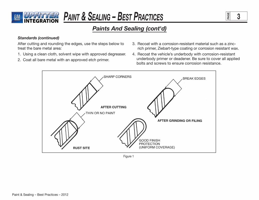
Paint & Sealing – Best Practices – 2012
Paint & Sealing – BeSt PracticeS 3PAG
E
Paints And Sealing (cont'd)Standards (continued)After cutting and rounding the edges, use the steps below to treat the bare metal area:
1. Using a clean cloth, solvent wipe with approved degreaser.
2. Coat all bare metal with an approved etch primer.
3. Recoat with a corrosion-resistant material such as a zinc-rich primer, Ziebart-type coating or corrosion resistant wax.
4. Recoat the vehicle’s underbody with corrosion-resistant underbody primer or deadener. Be sure to cover all applied bolts and screws to ensure corrosion resistance.
Figure 1
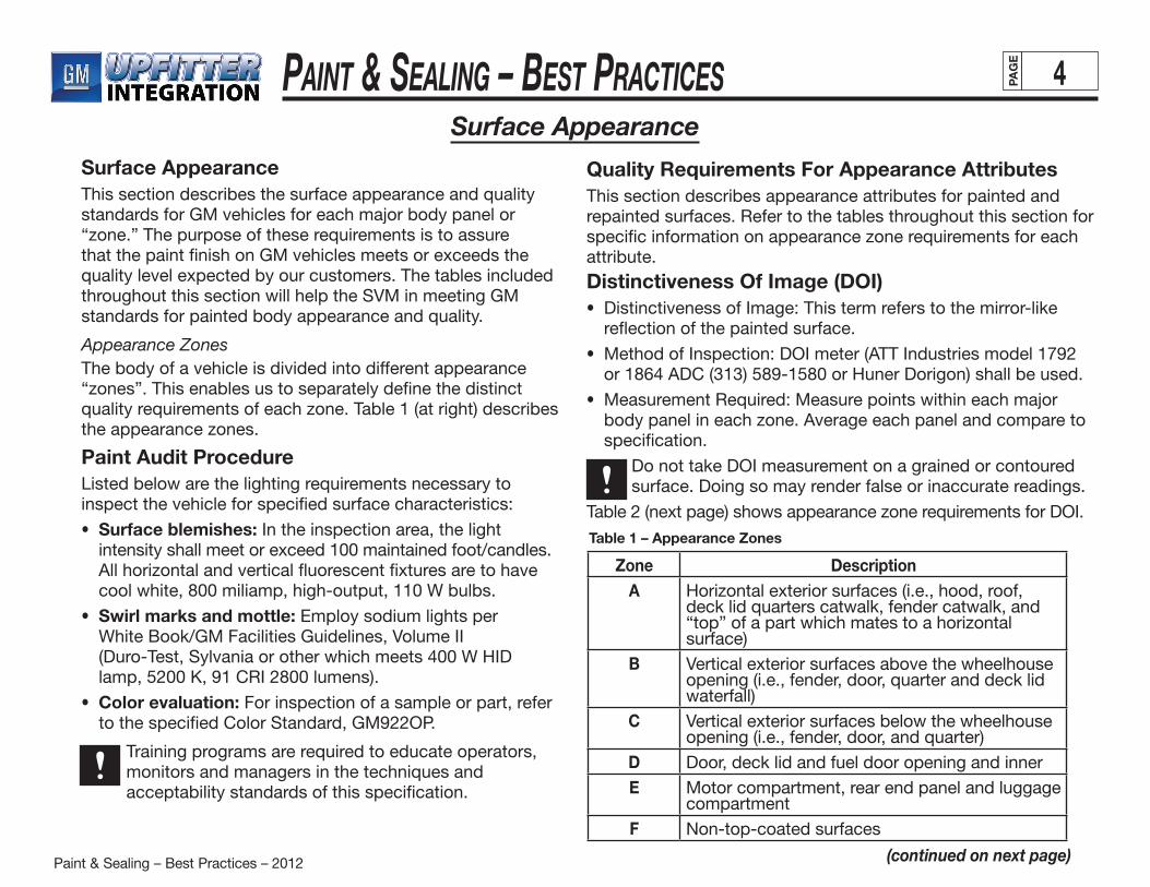
Paint & Sealing – Best Practices – 2012
Paint & Sealing – BeSt PracticeS 4PAG
E
Surface Appearance
(continued on next page)
Surface AppearanceThis section describes the surface appearance and quality standards for GM vehicles for each major body panel or “zone.” The purpose of these requirements is to assure that the paint finish on GM vehicles meets or exceeds the quality level expected by our customers. The tables included throughout this section will help the SVM in meeting GM standards for painted body appearance and quality.
Appearance ZonesThe body of a vehicle is divided into different appearance “zones”. This enables us to separately define the distinct quality requirements of each zone. Table 1 (at right) describes the appearance zones.
Paint Audit ProcedureListed below are the lighting requirements necessary to inspect the vehicle for specified surface characteristics:
• Surface blemishes: In the inspection area, the light intensity shall meet or exceed 100 maintained foot/candles. All horizontal and vertical fluorescent fixtures are to have cool white, 800 miliamp, high-output, 110 W bulbs.
• Swirl marks and mottle: Employ sodium lights per White Book/GM Facilities Guidelines, Volume II (Duro-Test, Sylvania or other which meets 400 W HID lamp, 5200 K, 91 CRI 2800 lumens).
• Color evaluation: For inspection of a sample or part, refer to the specified Color Standard, GM922OP.
Training programs are required to educate operators, monitors and managers in the techniques and acceptability standards of this specification.
Zone DescriptionA Horizontal exterior surfaces (i.e., hood, roof,
deck lid quarters catwalk, fender catwalk, and “top” of a part which mates to a horizontal surface)
B Vertical exterior surfaces above the wheelhouse opening (i.e., fender, door, quarter and deck lid waterfall)
C Vertical exterior surfaces below the wheelhouse opening (i.e., fender, door, and quarter)
D Door, deck lid and fuel door opening and innerE Motor compartment, rear end panel and luggage
compartmentF Non-top-coated surfaces
Table 1 – Appearance Zones
Quality Requirements For Appearance AttributesThis section describes appearance attributes for painted and repainted surfaces. Refer to the tables throughout this section for specific information on appearance zone requirements for each attribute.
Distinctiveness Of Image (DOI)• Distinctiveness of Image: This term refers to the mirror-like
reflection of the painted surface.
• Method of Inspection: DOI meter (ATT Industries model 1792 or 1864 ADC (313) 589-1580 or Huner Dorigon) shall be used.
• Measurement Required: Measure points within each major body panel in each zone. Average each panel and compare to specification.
Do not take DOI measurement on a grained or contoured surface. Doing so may render false or inaccurate readings.
Table 2 (next page) shows appearance zone requirements for DOI.

Paint & Sealing – Best Practices – 2012
Paint & Sealing – BeSt PracticeS 5PAG
E
(continued on next page)
Color Family Minimum ZoneColor Type Key A B C
Non-Metallic, Dark Metallic (N) (D) 86 75 75
Medium Metallic
Light Metallic(M) (L) 80 70 70
Special Metallic (S) 70 60 60
Table 2 – Distinctiveness of Image (DOI)
Surface Appearance (cont'd)
GlossGloss is the shininess or sheen of the painted surface.
• Method of Inspection: Glossmeter (20 degrees) as referenced in ASTM D523 (Gardner/Byk- Chemie, Humer or equivalent).
• Measurement Required: Measure points within each major body panel in a zone. Average each panel and compare to specification.
Do not take gloss measurement on a grained or contoured surface. Doing so may render false or inaccurate readings.
Table 3 (below) shows appearance zone requirementsfor gloss.
Color Minimum ZoneColor Type A B C D
All 80 80 80 60
Table 3 – Gloss
Orange PeelA rough or wavy appearance of the painted surface is referred to as “orange peel.” This condition is so named because it sometimes exhibits a texture which actually resembles that of an orange peel.
• Method of Inspection: Visual examination and comparison with standard orange peel panels.
Table 4 (below) shows appearance zone requirements for orange peel.
Zone MinimumA 7B 6C 5
Table 4 – Orange Peel
UniformityUniformity is the degree to which appearance is consistent over the entire vehicle, both within individual panels and between adjacent panels within a zone. The specifications for several appearance attributes are listed below:
• DOI: A maximum of 15 units difference is acceptable.
• Gloss: A maximum of 15 units difference is acceptable.
• Orange peel: A maximum of 2 levels difference is acceptable.
• Color: The color shall not vary from the Color Standard for Zones A, B, and C. A slight color difference from Standard is acceptable for Zone D.
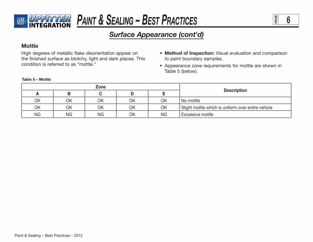
Paint & Sealing – Best Practices – 2012
Paint & Sealing – BeSt PracticeS 6PAG
E
Surface Appearance (cont'd)
MottleHigh degrees of metallic flake disorientation appear on the finished surface as blotchy, light and dark places. This condition is referred to as “mottle.”
• Method of Inspection: Visual evaluation and comparison to paint boundary samples.
• Appearance zone requirements for mottle are shown in Table 5 (below).
ZoneDescription
A B C D EOK OK OK OK OK No mottle
OK OK OK OK OK Slight mottle which is uniform over entire vehicle
NG NG NG OK NG Excessive mottle
Table 5 – Mottle
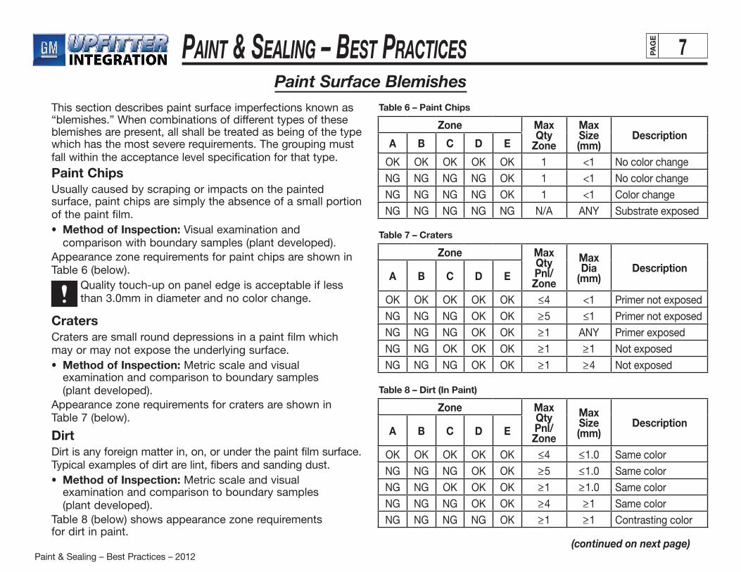
Paint & Sealing – Best Practices – 2012
Paint & Sealing – BeSt PracticeS 7PAG
E
(continued on next page)
Paint Surface BlemishesThis section describes paint surface imperfections known as “blemishes.” When combinations of different types of these blemishes are present, all shall be treated as being of the type which has the most severe requirements. The grouping must fall within the acceptance level specification for that type.
Paint ChipsUsually caused by scraping or impacts on the painted surface, paint chips are simply the absence of a small portion of the paint film.• Method of Inspection: Visual examination and
comparison with boundary samples (plant developed).Appearance zone requirements for paint chips are shown in Table 6 (below). Quality touch-up on panel edge is acceptable if less
than 3.0mm in diameter and no color change.
CratersCraters are small round depressions in a paint film which may or may not expose the underlying surface.• Method of Inspection: Metric scale and visual
examination and comparison to boundary samples (plant developed).
Appearance zone requirements for craters are shown in Table 7 (below).
DirtDirt is any foreign matter in, on, or under the paint film surface. Typical examples of dirt are lint, fibers and sanding dust.• Method of Inspection: Metric scale and visual
examination and comparison to boundary samples (plant developed).
Table 8 (below) shows appearance zone requirementsfor dirt in paint.
Zone Max Qty
Zone
Max Size (mm)
DescriptionA B C D E
OK OK OK OK OK 1 <1 No color change
NG NG NG NG OK 1 <1 No color change
NG NG NG NG OK 1 <1 Color change
NG NG NG NG NG N/A ANY Substrate exposed
Table 6 – Paint Chips
Zone Max Qty Pnl/ Zone
Max Dia
(mm)Description
A B C D E
OK OK OK OK OK <_4 <1 Primer not exposed
NG NG NG OK OK >_5 <_1 Primer not exposed
NG NG NG OK OK >_1 ANY Primer exposed
NG NG OK OK OK >_1 >_1 Not exposed
NG NG NG OK OK >_1 >_4 Not exposed
Table 7 – Craters
Zone Max Qty Pnl/ Zone
Max Size (mm)
DescriptionA B C D E
OK OK OK OK OK <_4 <_1.0 Same color
NG NG NG OK OK >_5 <_1.0 Same color
NG NG OK OK OK >_1 >_1.0 Same color
NG NG NG OK OK >_4 >_1 Same color
NG NG NG NG OK >_1 >_1 Contrasting color
Table 8 – Dirt (In Paint)
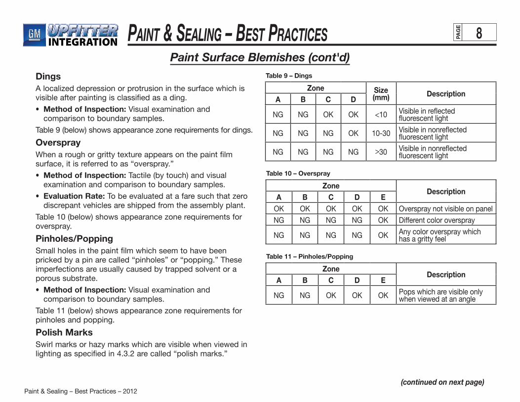
Paint & Sealing – Best Practices – 2012
Paint & Sealing – BeSt PracticeS 8PAG
E
Paint Surface Blemishes (cont'd)
(continued on next page)
DingsA localized depression or protrusion in the surface which is visible after painting is classified as a ding.
• Method of Inspection: Visual examination and comparison to boundary samples.
Table 9 (below) shows appearance zone requirements for dings.
OversprayWhen a rough or gritty texture appears on the paint film surface, it is referred to as “overspray.”
• Method of Inspection: Tactile (by touch) and visual examination and comparison to boundary samples.
• Evaluation Rate: To be evaluated at a fare such that zero discrepant vehicles are shipped from the assembly plant.
Table 10 (below) shows appearance zone requirements for overspray.
Pinholes/PoppingSmall holes in the paint film which seem to have been pricked by a pin are called “pinholes” or “popping.” These imperfections are usually caused by trapped solvent or a porous substrate.
• Method of Inspection: Visual examination and comparison to boundary samples.
Table 11 (below) shows appearance zone requirements for pinholes and popping.
Polish MarksSwirl marks or hazy marks which are visible when viewed in lighting as specified in 4.3.2 are called “polish marks.”
Zone Size (mm) Description
A B C D
NG NG OK OK <10 Visible in reflected fluorescent light
NG NG NG OK 10-30 Visible in nonreflected fluorescent light
NG NG NG NG > 30 Visible in nonreflected fluorescent light
Table 9 – Dings
ZoneDescription
A B C D EOK OK OK OK OK Overspray not visible on panel
NG NG NG NG OK Different color overspray
NG NG NG NG OK Any color overspray which has a gritty feel
Table 10 – Overspray
ZoneDescription
A B C D E
NG NG OK OK OK Pops which are visible only when viewed at an angle
Table 11 – Pinholes/Popping
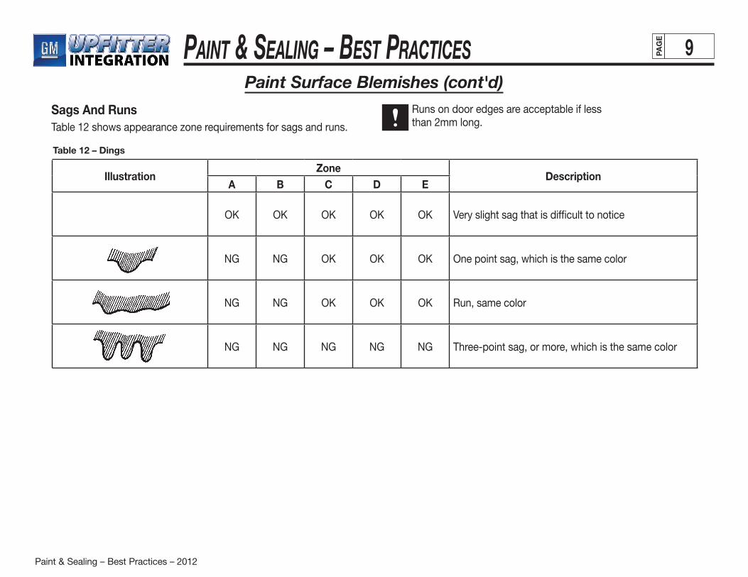
Paint & Sealing – Best Practices – 2012
Paint & Sealing – BeSt PracticeS 9PAG
E
Paint Surface Blemishes (cont'd)
Sags And RunsTable 12 shows appearance zone requirements for sags and runs.
Runs on door edges are acceptable if lessthan 2mm long.
IllustrationZone
DescriptionA B C D E
OK OK OK OK OK Very slight sag that is difficult to notice
NG NG OK OK OK One point sag, which is the same color
NG NG OK OK OK Run, same color
NG NG NG NG NG Three-point sag, or more, which is the same color
Table 12 – Dings
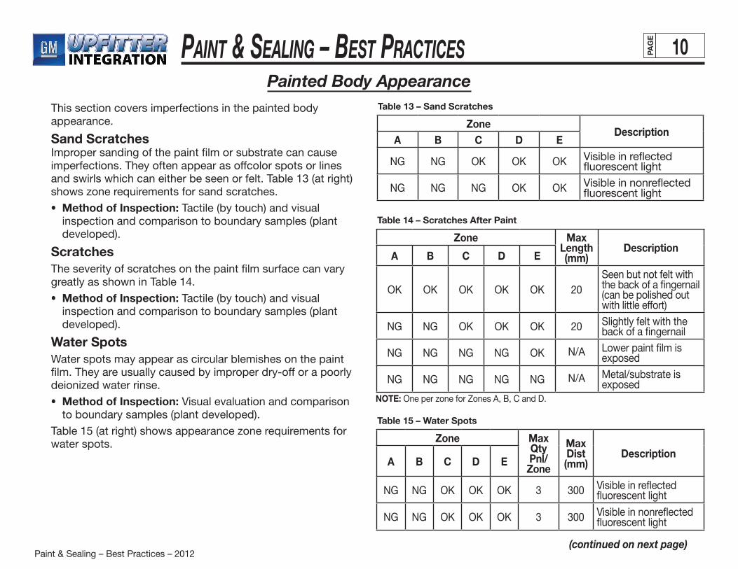
Paint & Sealing – Best Practices – 2012
Paint & Sealing – BeSt PracticeS 10PAG
E
Painted Body Appearance
(continued on next page)
This section covers imperfections in the painted body appearance.
Sand ScratchesImproper sanding of the paint film or substrate can cause imperfections. They often appear as offcolor spots or lines and swirls which can either be seen or felt. Table 13 (at right) shows zone requirements for sand scratches.
• Method of Inspection: Tactile (by touch) and visual inspection and comparison to boundary samples (plant developed).
ScratchesThe severity of scratches on the paint film surface can vary greatly as shown in Table 14.
• Method of Inspection: Tactile (by touch) and visual inspection and comparison to boundary samples (plant developed).
Water SpotsWater spots may appear as circular blemishes on the paint film. They are usually caused by improper dry-off or a poorly deionized water rinse.
• Method of Inspection: Visual evaluation and comparison to boundary samples (plant developed).
Table 15 (at right) shows appearance zone requirements for water spots.
ZoneDescription
A B C D E
NG NG OK OK OK Visible in reflected fluorescent light
NG NG NG OK OK Visible in nonreflected fluorescent light
Table 13 – Sand Scratches
Zone Max Qty Pnl/Zone
Max Dist (mm)
DescriptionA B C D E
NG NG OK OK OK 3 300 Visible in reflected fluorescent light
NG NG OK OK OK 3 300 Visible in nonreflected fluorescent light
Table 15 – Water Spots
Zone Max Length (mm)
DescriptionA B C D E
OK OK OK OK OK 20Seen but not felt with the back of a fingernail (can be polished out with little effort)
NG NG OK OK OK 20 Slightly felt with the back of a fingernail
NG NG NG NG OK N/A Lower paint film is exposed
NG NG NG NG NG N/A Metal/substrate is exposed
Table 14 – Scratches After Paint
NOTE: One per zone for Zones A, B, C and D.
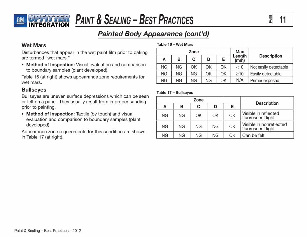
Paint & Sealing – Best Practices – 2012
Paint & Sealing – BeSt PracticeS 11PAG
E
Painted Body Appearance (cont'd)
Wet MarsDisturbances that appear in the wet paint film prior to baking are termed “wet mars.”
• Method of Inspection: Visual evaluation and comparison to boundary samples (plant developed).
Table 16 (at right) shows appearance zone requirements for wet mars.
BullseyesBullseyes are uneven surface depressions which can be seen or felt on a panel. They usually result from improper sanding prior to painting.
• Method of Inspection: Tactile (by touch) and visual evaluation and comparison to boundary samples (plant developed).
Appearance zone requirements for this condition are shown in Table 17 (at right).
ZoneDescription
A B C D E
NG NG OK OK OK Visible in reflected fluorescent light
NG NG NG NG OK Visible in nonreflected fluorescent light
NG NG NG NG OK Can be felt
Table 17 – Bullseyes
Zone Max Length (mm)
DescriptionA B C D E
NG NG OK OK OK <10 Not easily detectable
NG NG NG OK OK >_10 Easily detectable
NG NG NG NG OK N/A Primer exposed
Table 16 – Wet Mars
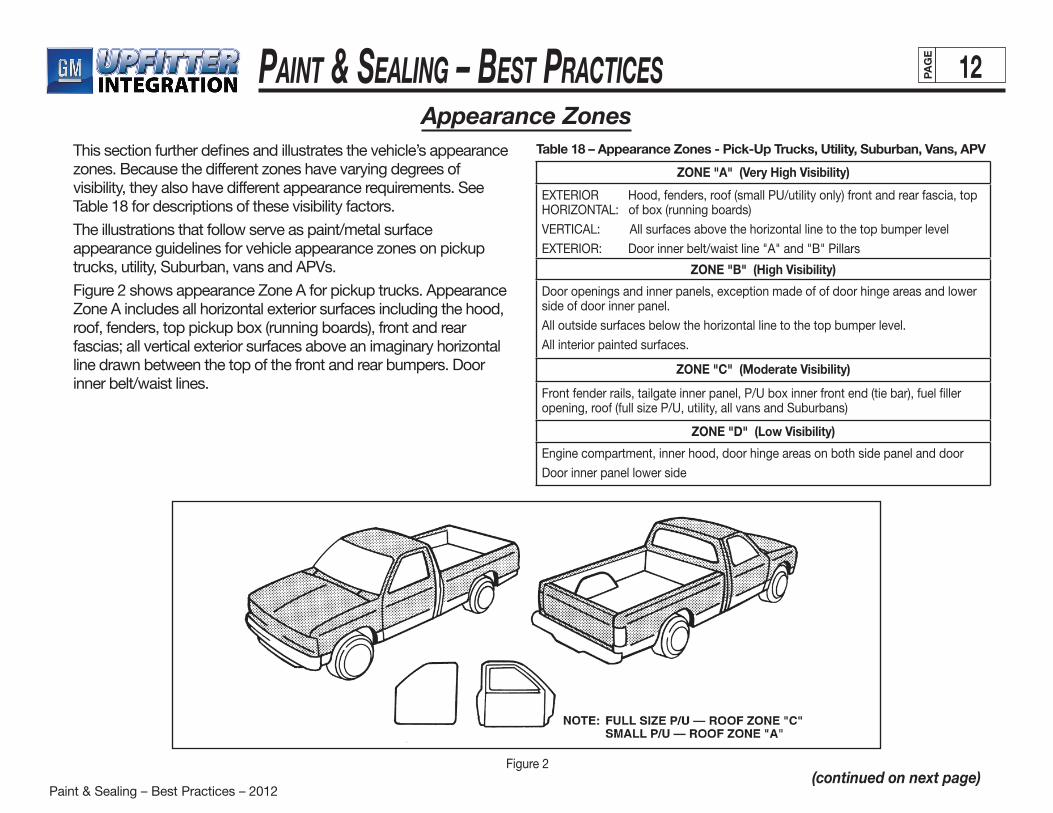
Paint & Sealing – Best Practices – 2012
Paint & Sealing – BeSt PracticeS 12PAG
E
Appearance Zones
(continued on next page)
This section further defines and illustrates the vehicle’s appearance zones. Because the different zones have varying degrees of visibility, they also have different appearance requirements. See Table 18 for descriptions of these visibility factors.
The illustrations that follow serve as paint/metal surface appearance guidelines for vehicle appearance zones on pickup trucks, utility, Suburban, vans and APVs.
Figure 2 shows appearance Zone A for pickup trucks. Appearance Zone A includes all horizontal exterior surfaces including the hood, roof, fenders, top pickup box (running boards), front and rear fascias; all vertical exterior surfaces above an imaginary horizontal line drawn between the top of the front and rear bumpers. Door inner belt/waist lines.
ZONE "A" (Very High Visibility)
EXTERIOR Hood, fenders, roof (small PU/utility only) front and rear fascia, top HORIZONTAL: of box (running boards)
VERTICAL: All surfaces above the horizontal line to the top bumper level
EXTERIOR: Door inner belt/waist line "A" and "B" Pillars
ZONE "B" (High Visibility)
Door openings and inner panels, exception made of of door hinge areas and lower side of door inner panel.
All outside surfaces below the horizontal line to the top bumper level.
All interior painted surfaces.
ZONE "C" (Moderate Visibility)
Front fender rails, tailgate inner panel, P/U box inner front end (tie bar), fuel filler opening, roof (full size P/U, utility, all vans and Suburbans)
ZONE "D" (Low Visibility)
Engine compartment, inner hood, door hinge areas on both side panel and door
Door inner panel lower side
Figure 2
Table 18 – Appearance Zones - Pick-Up Trucks, Utility, Suburban, Vans, APV
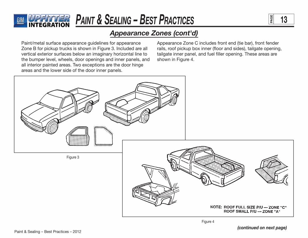
Paint & Sealing – Best Practices – 2012
Paint & Sealing – BeSt PracticeS 13PAG
E
Appearance Zones (cont'd)
(continued on next page)
Paint/metal surface appearance guidelines for appearance Zone B for pickup trucks is shown in Figure 3. Included are all vertical exterior surfaces below an imaginary horizontal line to the bumper level, wheels, door openings and inner panels, and all interior painted areas. Two exceptions are the door hinge areas and the lower side of the door inner panels.
Appearance Zone C includes front end (tie bar), front fender rails, roof pickup box inner (floor and sides), tailgate opening, tailgate inner panel, and fuel filler opening. These areas are shown in Figure 4.
Figure 3
Figure 4

Paint & Sealing – Best Practices – 2012
Paint & Sealing – BeSt PracticeS 14PAG
E
(continued on next page)
Figure 5
Figure 6
Appearance Zones (cont'd)
Figure 5 illustrates appearance Zone D for pickup trucks. This zone includes the engine compartment, hood inner panel, door hinge areas in door openings and door inner panels, and the lower side of the door inner panels.
Appearance Zone C for utility trucks includes the front end (tie bar), front fender rails and fuel opening. See Figure 6.
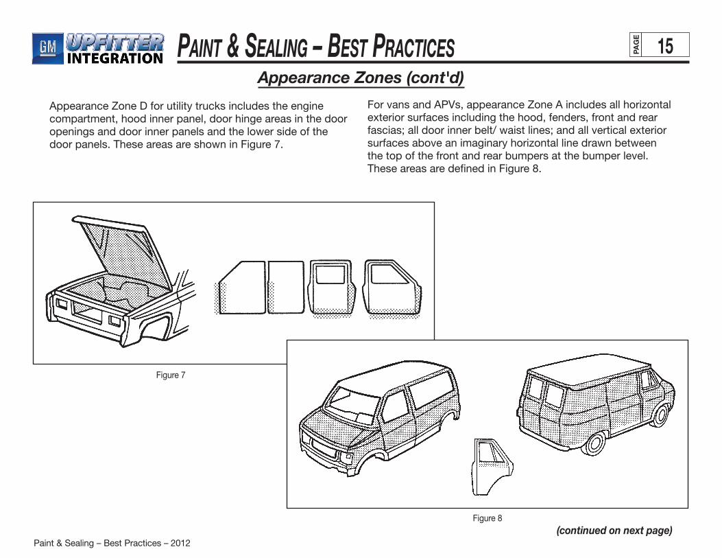
Paint & Sealing – Best Practices – 2012
Paint & Sealing – BeSt PracticeS 15PAG
E
Figure 7
(continued on next page)
Appearance Zone D for utility trucks includes the engine compartment, hood inner panel, door hinge areas in the door openings and door inner panels and the lower side of the door panels. These areas are shown in Figure 7.
Figure 8
For vans and APVs, appearance Zone A includes all horizontal exterior surfaces including the hood, fenders, front and rear fascias; all door inner belt/ waist lines; and all vertical exterior surfaces above an imaginary horizontal line drawn between the top of the front and rear bumpers at the bumper level. These areas are defined in Figure 8.
Appearance Zones (cont'd)
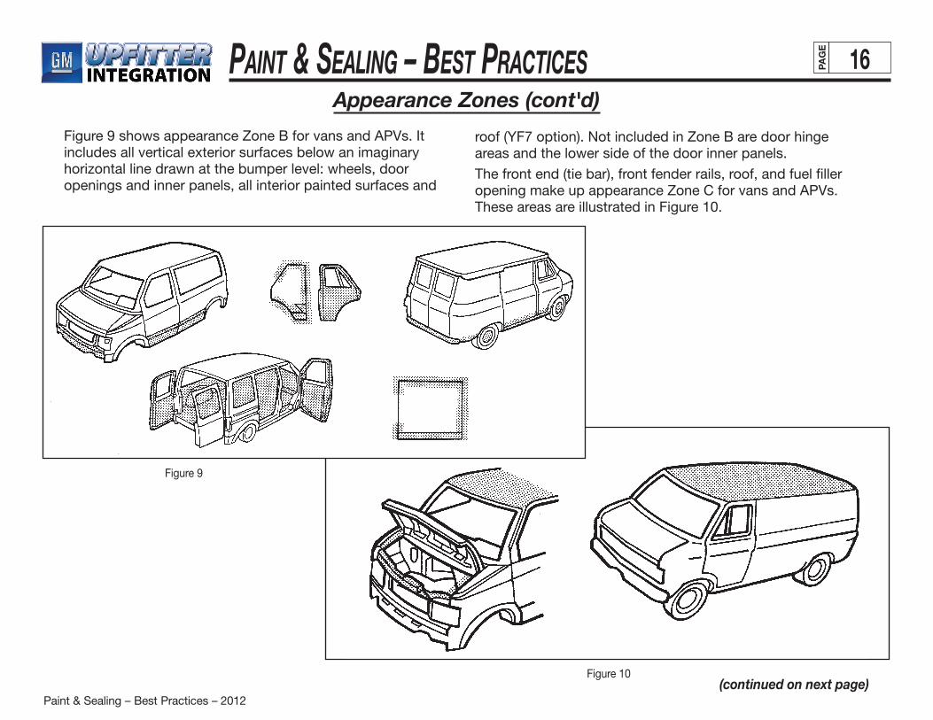
Paint & Sealing – Best Practices – 2012
Paint & Sealing – BeSt PracticeS 16PAG
E
(continued on next page)
Appearance Zones (cont'd)
Figure 9 shows appearance Zone B for vans and APVs. It includes all vertical exterior surfaces below an imaginary horizontal line drawn at the bumper level: wheels, door openings and inner panels, all interior painted surfaces and
roof (YF7 option). Not included in Zone B are door hingeareas and the lower side of the door inner panels.
The front end (tie bar), front fender rails, roof, and fuel filler opening make up appearance Zone C for vans and APVs. These areas are illustrated in Figure 10.
Figure 10
Figure 9

Paint & Sealing – Best Practices – 2012
Paint & Sealing – BeSt PracticeS 17PAG
E
Zone D for vans and APVs includes the engine compartment, hood inner panel, door hinge areas in the door openings and inner panels, and the lower side of the door inner panels (front, side, rear). Figure 11 shows these areas.
Appearance Zones (cont'd)
Figure 11
PreparationA good paint job requires proper surface preparation. The weak base resulting from poor preparation eventually results in the overall failure of the finish. This section describes preparation for two types of surfaces:
• previously painted
• bare substrate
Painted SurfacesThe steps below describe the preparation for painted surfaces:
1. Wash the painted area thoroughly to remove as much contamination as possible. This will also eliminate dust and dirt.
2. When applying a new finish over an old one, solvent clean the old finish. This removes wax and other contaminates that can harm the new finish and cause loss of adhesion.
3. Fold a clean, dry cotton cloth. Soak it with a solvent (see General Motors specifications for solvents) made expressly for this purpose and apply to the old painted surface. While the surface is still wet, fold a second clean cloth and wipe dry. Work small areas so the surface can be wiped clean before it dries.
4. Measure and record the original film thickness before sanding. This ensures that maximum total film builds of 11 mils for OEM (14 mils with powder prime) and 12 mils refinish are not exceeded.
Use an electronic paint gauge to measure film thickness. Consult Appendix III of this manual for additional information.
After sanding or grinding, it may be necessary to further clean the surface prior to any filling or painting.
Unpainted SurfacesProper metal treatment is critical to the success of every painting operation. Poor adhesion and corrosion can result when the surface is treated improperly or carelessly. Always chemically clean bare metal surfaces to ensure optimum adhesion for the undercoat.

Paint & Sealing – Best Practices – 2012
Paint & Sealing – BeSt PracticeS 18PAG
E
(continued on next page)
Paint Systems And Procedures
GM-Approved Refinish MaterialsGeneral Motors continuously pursues quality improvement. Therefore GM has established automotive refinishing standards for itself as well as its Marketing Division Dealers and Retailers. GM is the first domestic car company to set a specification for aftermarket paint finishes.
GM has established standards for paint refinishing. Each Division requires the Dealer to use only materials and methods that meet GM Standard GM4901M when repairing, replacing, or refinishing vehicles. Where it is determined that the Dealer is using paint systems or materials which do not meet GM4901M standards, appropriate counsel and/or corrective action may be taken.
The Bottom LineThe Dealer or Retailer must ensure that all finish repairs, including sublets, meet GM Specification GM4901M. Use of materials (and associated methods) that do not meet this GM standard may result in a review of claim(s) leading to chargeback(s).
As warranty periods increase, customer expectations continue to rise. Many Dealers/Retailers understand customer expectations. As a result, they have chosen a single, complete system approach and only use the systems that meet the highest standards of quality and durability.
All the paint manufacturers that meet the GM4901M Specification have spent thousands of manhours in research and development to ensure the approved system gives the appearance, performance, and durability comparable to the OEM finish. The products in the systems listed in this bookare the very best products to use. They are guaranteed to produce the consistent, quality results that GM customers expect. This makes it easier for you, as the Dealer/Retailer,
to confidently choose a system that will maximize your customers’ satisfaction.
Each year, all new paint systems will be tested and evaluated. New or improved products will also be tested. The paint systems that pass this annual testing process will be published in this booklet, updated annually.
For further information on these systems, call the STG Center, at 1-810-575-1906.
If booklets are needed, call 1-800-269-5100.See Appendix II of this manual for additional information for GM4901M standards and approved sources.
UndercoatsLike surface preparation, proper undercoating is necessary to achieve an attractive, durable topcoat. It is important to use the right undercoat for the job and to apply it promptly following surface preparation.
There are four types of undercoats:
• Prepcoats
• Primer-surfacers
• Primer-sealers
• Sealers
Paint & Sealing – Best Practices – 2012
Paint & Sealing – BeSt PracticeS 19PAG
E
(continued on next page)
Paint Systems And Procedures (cont'd)
Prepcoats (Etch Primers)Prepcoats prepare the bare metal substrate to accept and hold the color coat. They do this by providing adhesion to the surface and producing a corrosion-resistant foundation. Prepcoats do not fill well and are used in conjunction with a primer-surfacer.
Self-etching prepcoats provide excellent adhesion. Also used as prepcoats are zinc chromate primers, which protect steel and aluminum against rusting or corrosion. Prior to assembly, a coat of this primer can be sprayed where dissimilar metalscontact each other. This prevents the electrolytic action that causes rapid corrosion of the metal.
Primer-SurfacersApplied prior to basecoat clear coat application, primer-surfacers build up the base required for sanding. GM recommends two applications of primer-surfacer, with the second application color keyed to topcoat.
Good primer-surfacer characteristics are:
• The ability to create a strong bond or adhesion between the substrate and the applied topcoat.
• Corrosion resistance to prevent disintegration of the metallic substrate.
• The ability to “build” or cover all surface imperfections (i.e., grind marks, sand scratches, etc.).
• Ability to sand smoothly and level quickly and easily.
• “Hold out” or sealing quality to prevent the topcoat from “striking” into the film causing a dull look.
• Quick drying speed, allowing sanding within a reasonable time.
Always measure primer quality per GM specifications (see Appendix I).
Primer-SealersPrimer-sealers provide the same protection as prepcoats: adhesion and corrosion resistance. They also have the ability to seal a sanded old finish to provide uniform color hold-out.
Primer-sealers can be used to prime a bare surface and as a sealer under any enamel topcoat.
Sealers (Adhesion Promoters)Sealers perform three basic functions:
• Improve adhesion between the old finish and the new
• Provide uniform color background and holdout for the topcoat
• Provide a solvent barrier to help prevent sandscratch swelling and show-through
Unlike primers, sealers are sprayed over prepcoats, primer surfaces, or sanded old finishes.
Clearcoat areas must be sealed prior to repainting.
• Sealers are not used as primers. They are sprayed over prepcoats or primer surfaces, or sanded old finishes.
• Before applying a sealer, all surfaces must be thoroughly scuff-sanded (no glossy areas). This prevents delamination.
Paint & Sealing – Best Practices – 2012
Paint & Sealing – BeSt PracticeS 20PAG
E
(continued on next page)
Putties And FillersPutties and body fillers (while not precisely undercoats) can be termed “solid” undercoats.
• A putty is a paste and has a much heavier body than a primer-surfacer. It is used to fill any small imperfections or flaws remaining in the substrate after primer-surfacer has been applied. Putty must be sanded.
• Body fillers are an extremely durable polyester plastic material that sands smooth after drying. It is used to fill large flaws before either primer or putty is applied.
TopcoatFrom the customer’s standpoint, the topcoat is the most important step in the painting operation. This is because the customer sees only the topcoat and judges the quality of the entire paint job on its appearance.
BasecoatThe first step in color matching is to select the proper topcoat color. Paint quality and durability must meet the requirements of GM specification 4901M (refinish materials).
ClearcoatClearcoat quality must meet the requirements of GM specification 4901M. A minimum thickness of 1.5 mils is necessary to protect the finish from ultraviolet penetration.
Accurate measurements of the clearcoat application ensures that the 1.5-mil minimum film-build is maintained. An OEM finish finessed to match the surface of the newly painted area must be accurately measured before and after finesse to ensure that 1.5 mils minimum of clearcoat remain on theunit (0.5 mil maximum clearcoat removal). See Appendix III of this manual for film thickness measuring device.
Paint Systems And Procedures (cont'd)
Finesse/Clear And PolishAccurate measurements of the clearcoat application ensures that the 1.5-mil minimum film-build is maintained. An OEM finish finessed to match the surface of the newly painted area must be accurately measured before and after finesse to ensure that 1.5 mils minimum of clearcoat remain on theunit (0.5 mil maximum clearcoat removal). See Appendix III of this manual for film thickness measuring device.
Sanding (Primer)Sanding removes defects from a surface and prepares it to receive a topcoat. Two methods are moist sanding and wet sanding. Great care must be taken with either method to avoid sand-through, which will adversely affect the appearance and durability of the finished product.Before any detail or hand-sand operation, it is important to classify exterior body panels as Zone A, B or C. Sharp edges or surface profiles not accessible by mechanical sanding should have an 8- to 12-mil gap between those areas and the areas sanded, as required. This gap range should alwaysbe detailed by hand.Sanding through the primer surface or electro-deposited primer is not acceptable. These important layers guard against accelerated corrosion and paint failure.
Moist SandingMoist sanding is one method of defect removal which is preferable to the more labor-intensive operation of complete wet sanding. It allows the operator to inspect the surface for visible defects — such as dirt and sags — prior to painting. Moist sanding should be performed in an enclosed booth to avoid contaminating the entire paint shop with sanding residue. Compatibility of the primer with water must be verified with the supplier.
Paint & Sealing – Best Practices – 2012
Paint & Sealing – BeSt PracticeS 21PAG
E
Moist Sanding (cont'd)The general sanding process follows:
1. Cool units to below 37.8ºC before sanding.
2. Use sandpaper with ANSI 400 grit or higher so that defects can be removed without producing sand scratches that are visible after topcoat application. If sand scratches are visible, reprocess with finer-grit sandpaper.
3. Thoroughly soak sandpaper prior to use. Spray area to be sanded with water to lubricate the work surface.
4. Remove the defect by sanding in a circular motion. This prevents uni-directional sand scratches.
5. Once the defect is removed, wipe the surface with a clean, lint-free cloth.
6. After removing all defects from the unit, wipe the entire surface with a 50/50 isopropyl alcohol/water mixture. This should remove any contamination that remains after moist sanding.
Tack-off, followed by air blow-off, must be completed before applying the next coat.
Wet SandingDepending on the surface contour, type of primer, and detail requirements of the unit, wet sanding may be preferable to mechanical methods.
The known hardness of the surfaces to be sanded and the surface profile of the unit determine theselection of equipment and materials (screen-cloth grit and size). Selection criteria should include (but not limited by) evaluation of sand scratches which result from the process and are not visible after topcoat application.
Maintaining a sufficient amount of water is critical to wet
sanding. This avoids uneven cutting of the unit surface. After the last wet sand operation, a high-pressure rinse is required to remove all excess surface contamination that could affect the topcoat or its durability. A final rinse of deionized (DI) water should follow to remove all salts or foreign materials that affect topcoat quality.
When wet sanding by mechanical methods, always use multiple, uniform cuts on horizontal and vertical surfaces. This ensures that wet sand screen swirl cuts and other defects are not visible after topcoat application. Rinse screens as often as necessary with water to free any wet sand residue or abrasive particles that may lodge within the screen itself.
IonizersSanding, finesse, detailing, tack-off and other assembly plant operations may deliver a static charge to the unit. The static charge in turn is a potential attraction for dirt or other surface contaminants. Ionizers are used to neutralize static charges. It is acceptable to use an ionizing air blow-off to blow dust, dirt and sanding particles from the unit. This process reduces static and imperfections in subsequent painting applications.
Paint Systems And Procedures (cont'd)
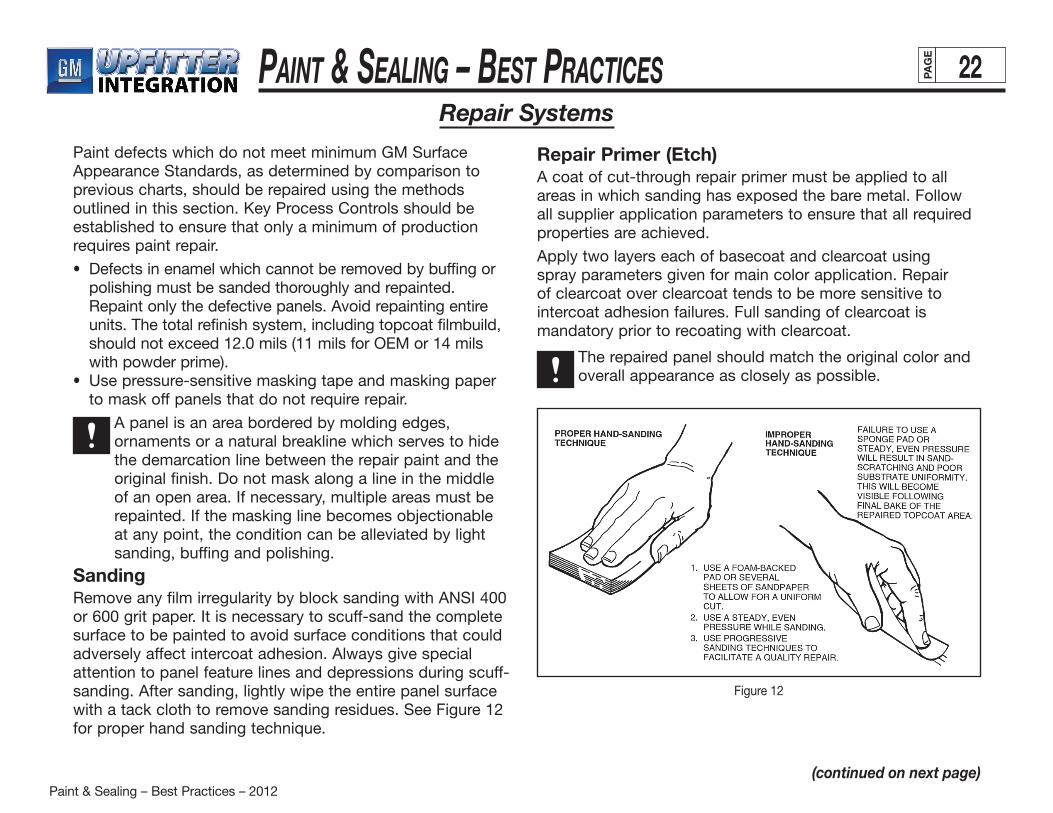
Paint & Sealing – Best Practices – 2012
Paint & Sealing – BeSt PracticeS 22PAG
E
Repair Systems
Paint defects which do not meet minimum GM Surface Appearance Standards, as determined by comparison to previous charts, should be repaired using the methods outlined in this section. Key Process Controls should be established to ensure that only a minimum of production requires paint repair.
• Defects in enamel which cannot be removed by buffing or polishing must be sanded thoroughly and repainted. Repaint only the defective panels. Avoid repainting entire units. The total refinish system, including topcoat filmbuild, should not exceed 12.0 mils (11 mils for OEM or 14 mils with powder prime).
• Use pressure-sensitive masking tape and masking paper to mask off panels that do not require repair.
A panel is an area bordered by molding edges, ornaments or a natural breakline which serves to hide the demarcation line between the repair paint and the original finish. Do not mask along a line in the middle of an open area. If necessary, multiple areas must be repainted. If the masking line becomes objectionable at any point, the condition can be alleviated by light sanding, buffing and polishing.
SandingRemove any film irregularity by block sanding with ANSI 400 or 600 grit paper. It is necessary to scuff-sand the complete surface to be painted to avoid surface conditions that could adversely affect intercoat adhesion. Always give specialattention to panel feature lines and depressions during scuff-sanding. After sanding, lightly wipe the entire panel surface with a tack cloth to remove sanding residues. See Figure 12 for proper hand sanding technique.
Repair Primer (Etch)A coat of cut-through repair primer must be applied to all areas in which sanding has exposed the bare metal. Follow all supplier application parameters to ensure that all required properties are achieved.
Apply two layers each of basecoat and clearcoat using spray parameters given for main color application. Repair of clearcoat over clearcoat tends to be more sensitive to intercoat adhesion failures. Full sanding of clearcoat is mandatory prior to recoating with clearcoat.
The repaired panel should match the original color and overall appearance as closely as possible.
Figure 12
(continued on next page)
Paint & Sealing – Best Practices – 2012
Paint & Sealing – BeSt PracticeS 23PAG
E
Spot RepairFull panel repair can be avoided if the defect is isolated in size and location. Spot repairs do not work well in the center of a vertical or horizontal surface and may not be applicable to all colors (e.g., high metallic).
Repairs are more difficult to detect if they are ended along a feature line or panel edge. This method camouflages the differences between the OEM finish and the spot repair.
It is critical to apply clearcoat within sanded areas only. Recoat does not adhere to unsanded high-bake clearcoat.
SandingSpot repairs require sanding the defect and the surrounding area to which basecoat and/or clearcoat will be applied. Use a grit size no coarser than ANSI 400 to 600 grit for final sanding. This reduces the chance of sand scratches telegraphing through the repair topcoat. Feather out approximately 5 or 6 inches from the defect area withANSI 1200 to 1500 wet grit paper to facilitate the final finesse operation. Wipe off all sanding residue with a clean, lint-free towel dampened with naphtha or 1:1 water/isopropyl alcohol. Tack off.
Repair PrimerApply repair primer-sealer to sand-through area only, using a gravity-feed cup gun. The recommended dry film thickness is 1.0 to 1.5 mils.
Hand sand with moist ANSI 400-600 grit paper to promote topcoat adhesion. To avoid the telegraphing of sand scratches, do not sand outer area of repair previously sanded with ANSI 1200/1500 grit paper.
Color CoatColor is applied to essentially three zones which feather into each other:
• Basecoat and clearcoat are applied to the defect area, which has been previously primed.
• Full clearcoat is applied beyond the basecoat and feathered.
• When topcoat application is completed, a halo of ANSI 1200-1500 grit-sanded area surrounding the repair must remain because clearcoat will not adhere to unsanded original clearcoat.
Polishing is required to blend the repair area with the surrounding panel. The original clearcoat, ANSI 1200-1500 grit-sanded area at the periphery, and the repaired area must all match in color and appearance.
Touch-Up RepairUse air-dry touch-up materials to repair minor chips and scratches only in those areas where appearance quality is not compromised (that is, on secondary surfaces and partially hidden edges). Never perform touch-up repairs within exteriorbody panels or on chips and scratches that have exposed bare metal.
Apply repair material only to the damaged area with minimal overlap onto the surrounding area.
Some metallic colors require a clear touchup paint in addition to the color coat.
Lacquer-type materials do not adhere to enamel clearcoats without sanding and use of primer-sealer.
CAUTION
Repair Systems (cont'd)
(continued on next page)
Paint & Sealing – Best Practices – 2012
Paint & Sealing – BeSt PracticeS 24PAG
E
(continued on next page)
Application of up to three coats (sealer, color coat and clearcoat) requires considerable finesse to obtain acceptable appearance. Some polishing may also be required.
Enamel-type touch-up materials are preferable.
Some general guidelines for touch-up repairs are:
• Clean the area surrounding chip or scratch with naphtha to remove any grease, oil or other contaminants. Wipe dry with a clean, dry, lint-free cloth.
• If application of repair material is limited to mutilated area, it is not necessary to sand or apply primer to obtain adhesion.
• If repair material is applied to adjacent area (1/8 inch maximum), apply a light coat of primer-sealer to the repair area. Do not apply sealer to areas which will not receive repair paint. Alternately, the adjacent area may be sanded with ANSI 600 grit sandpaper, followed by ANSI 1200 grit sandpaper. This allows polishing to remove sanding scratches if required.
• Apply sufficient color coat to achieve hiding and color match before applying clearcoat.
• Nominal film-builds are 1.5 to 2.0 mils.
• Ifnecessarytoblendrepairedspotwithsurroundingarea,allow to air dry for 24 hours (or equivalent using heat source) and finesse polish.
Repair Systems (cont'd)
Spot Finesse Sanding/PolishingBasecoat/ClearcoatThis process can be used to repair minor scratches, dirt, dull spots and related defects in the clearcoat without resorting to repainting. It may be performed before or after repairs. Do not use this method to repair major defects such as large sags, solvent pops, craters or basecoat defects.Prior to finesse and repair, inspect the body for all paint defects in a well-lighted area (100 foot-candle lighting minimum). Use this method only on paint which is sufficiently cured and has cooled to 100ºF or below. Otherwise, objectionable swirl marks and other appearance deficiencies may result. Be very careful during each step of the process to remove as little of the clearcoat as possible.
Removing DefectsThe approved method for removing defects, such as dirt protruding above the clearcoat surface, is by hand-planing with a file. You may attach a wood block to the file to facilitate the operation. Grasp the tool firmly. Gently shave the imperfection, using several strokes in one direction only.
Apply minimum pressure and concentrate in the area of the defect only to avoid removing the surrounding clearcoat.
Clean and sharpen the file periodically to achieve proper defect removal.
SandingAfter removing the defect, lightly hand-sand the area. Use a special finesse sanding block with ANSI 1200 or 1500 grit paper and lubricating fluid. Use a circular motion, applying minimum pressure to avoid deep scratches, until defect is uniform with surrounding area. After sanding, wipe the affected area with a clean, lint-free cloth.
CAUTION
Paint & Sealing – Best Practices – 2012
Paint & Sealing – BeSt PracticeS 25PAG
E
(continued on next page)
Repair Systems (cont'd)
Do not sand excessively around the defect area. Reducing the clearcoat’s thickness will affect durability.
A minimum of 1.5 mils clearcoat must remain (0.5 mil maximum removal). Otherwise, the affected area must be recoated.
Finesse Polish (Rotary)Follow the steps below to remove any fine scratches created by sanding:
1. Apply one 3/8 inch drop of specific finesse polishing compound per sanded spot.
2. Using a polish pad, evenly smear the compound over the sanded area before running the wheel.
3. While running the wheel, keep the pad flat, directly over the sanded spot. Operate the tool with a 1- to 2-inch circular motion to randomize the swirl pattern. Apply only enough pressure to maintain uniform contact with the surface. Polish panel edges and sharp contours lightly to avoid cut-through.
Inspect the polished area. Apply more polish, repeating as needed. When all sand scratches have been removed and the finish is uniform and glossy, the unit is ready for buffing. There is no need to remove polish residue.
Final Buffing (Orbital)Final orbital buffing removes any swirl marks left by rotary polishing.
Apply additional finesse polishing compound or specified finesse buffing compound to each polished spot. Using an orbital buffing wheel, evenly smear the compound over the polished spot before operating the wheel. Begin buffing in the center of the swirl pattern. Use a slight back-and-forthmotion and buff approximately 3 inches beyond the pattern. This will blend the refinished spot with the surrounding area.
Apply enough pressure to prevent free motion of the motor. Do not restrict the motor’s dual action. This action helps to minimize the objectionable continuous swirl pattern.
After buffing, mist the area with 50/50 water/ isopropyl alcohol blend. Wipe with a soft cloth to remove polish residue. Inspect the surface under sunlight or sodium vapor lights. If it is not uniform and free of swirls or haze, repeat the buffing operation.
CAUTION
Paint & Sealing – Best Practices – 2012
Paint & Sealing – BeSt PracticeS 26PAG
E
(continued on next page)
Manual Spray Guns And Applications
This section covers proper techniques for applying paint by hand. It is for informational purposes only. Major suppliers provide training in the proper spray application of their products. Specific questions should be addressed to them. See Appendix I of this manual for information on hand spray- gun operation and maintenance.Good hand spraying technique (Figures 13, 14, and 15) ensures a uniform surface of specified gloss, DOI, texture, film-build and color. Proper technique requires attention to many elements, including:
• fluiddeliverysettings
• applicationstrokeoverlapandlength
• triggeringpoints
• spraypatternadjustment
• surfacecontour
• paintmaterialcharacteristics
• film-buildrequirements
• handgun-to-workorientationanddistanceSeveral trial sprays may be necessary to establish an ideal, repeatable technique. The following table (Table 19) outlines topcoat process controls by describing the relationship between application parameters and appearance or perfor- mance attributes for typical processing situations. Para-meters are often interdependent. That is, changing one can influence another. Many of the “typical” cases indicate general trends only for specific parameters.Color is directly related to pigment strength, pigment loading, and degree of dispersion and metal flake orientation. Metal flake orientation is the area most influenced by application parameters. The orientation of metal determines how much pigment is exposed. See Figure 16 (on page 29).
• Lightercolorsareproducedwhenmorealuminumand less pigment is exposed.
• Darkercolorsresultfrommorealuminumdisorientation.• Highdegreesofmetaldisorientationcauseblotches,light
and dark patches commonly referred to as “mottle.”• Twofactorsinfluencemetalorientation: — the kinetic energy of the paint particle striking the
work place. — the on-panel viscosity of the applied paint film.Energy of the striking particle determines the initial metal configuration. The flow of film and evaporation of solvents determines the degree of aluminum or mica movement in the film. Generally, the lower the on-panel viscosity (i.e., wetter film), the darker the color. The higher (drier film) the on-panel viscosity, the less disorientation of metallic flake and the lighter the color.Two processes compete in achieving desirable appearance:• Agoodwetfilmassuresgoodflow.Thegoodflowofa
paint film prevents “orange peel.” This condition tends to scatter light and reduce DOI.
• Atthesametime,themovementofaluminumormicashould be restricted to prevent dark color or mottling, which requires a drier film.
At this point the proper split-up of coats can solve the problem. Applying an initial wet coat assures good flow. Following this with a drier second coat assures good metal orientation. Make sure that the initial coat is wet enough to allow
good fusion of the two coats; but not so wet that solvents quickly migrate into the final dust coat causing metal disorientation from over-fusion of the coats. See Figure 13 (next page).
CAUTION
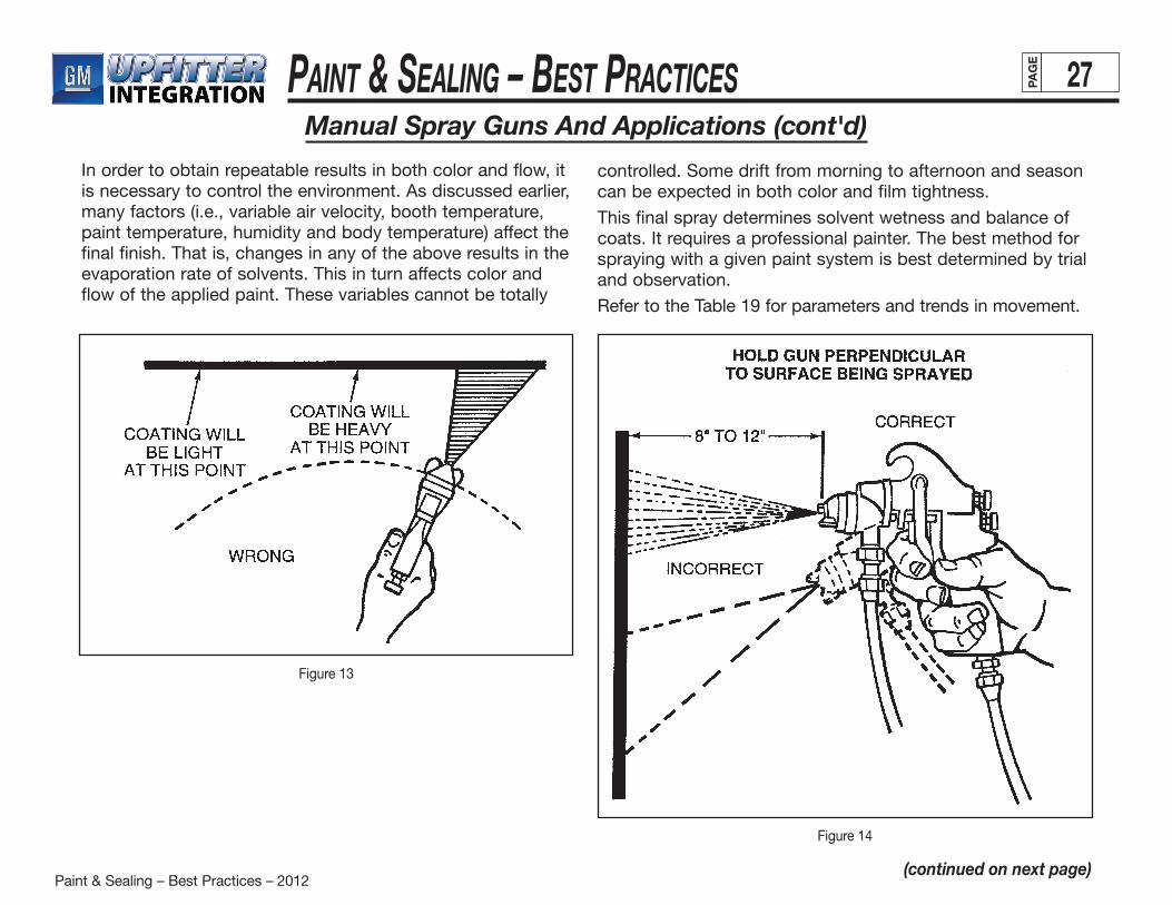
Paint & Sealing – Best Practices – 2012
Paint & Sealing – BeSt PracticeS 27PAG
E
(continued on next page)
Manual Spray Guns And Applications (cont'd)
In order to obtain repeatable results in both color and flow, it is necessary to control the environment. As discussed earlier, many factors (i.e., variable air velocity, booth temperature, paint temperature, humidity and body temperature) affect the final finish. That is, changes in any of the above results in the evaporation rate of solvents. This in turn affects color and flow of the applied paint. These variables cannot be totally
controlled. Some drift from morning to afternoon and seasoncan be expected in both color and film tightness.
This final spray determines solvent wetness and balance of coats. It requires a professional painter. The best method for spraying with a given paint system is best determined by trial and observation.
Refer to the Table 19 for parameters and trends in movement.
Figure 13
Figure 14
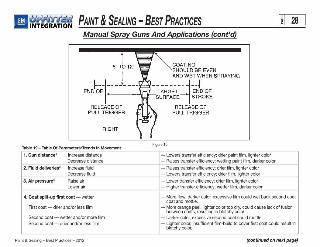
Paint & Sealing – Best Practices – 2012
Paint & Sealing – BeSt PracticeS 28PAG
E
(continued on next page)
Manual Spray Guns And Applications (cont'd)
Figure 15Table 19 – Table Of Parameters/Trends In Movement
1. Gun distance* Increase distance Decrease distance
— Lowers transfer efficiency; drier paint film. lighter color— Raises transfer efficiency; wetting paint film, darker color
2. Fluid deliveries* Increase fluid Decrease fluid
— Raises transfer efficiency; drier film, lighter color— Lowers transfer efficiency; drier film, lighter color
3. Air pressure* Raise air Lower air
— Lower transfer efficiency; drier film, lighter color— Higher transfer efficiency; wetter film, darker color
— More flow, darker color, excessive film could wet back second coat coat and mottle.
— More orange peel, lighter color too dry, could cause lack of fusion between coats, resulting in blotchy color.
— Darker color, excessive second coat could mottle.— Lighter color, insufficient film-build to cover first coat could result in
blotchy color.
4. Coat split-up first coat — wetter
First coat — drier and/or less film
Second coat — wetter and/or more film Second coat — drier and/or less film
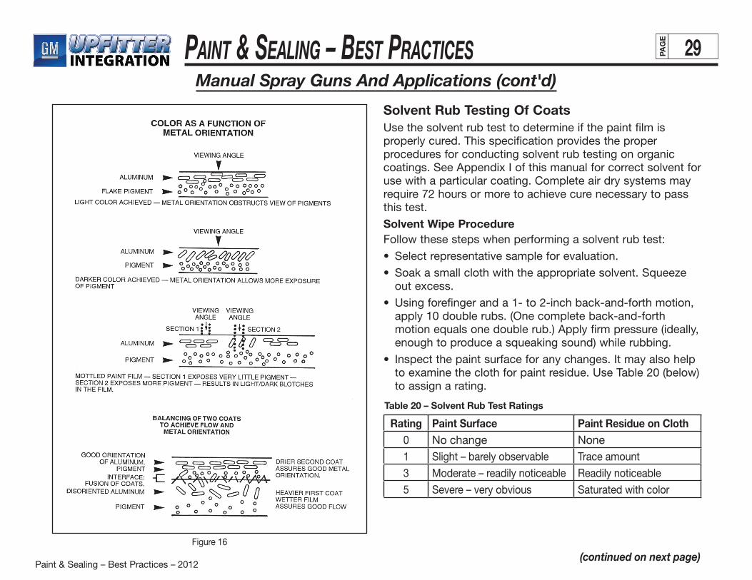
Paint & Sealing – Best Practices – 2012
Paint & Sealing – BeSt PracticeS 29PAG
E
(continued on next page)
Manual Spray Guns And Applications (cont'd)
Figure 16
Solvent Rub Testing Of CoatsUse the solvent rub test to determine if the paint film is properly cured. This specification provides the proper procedures for conducting solvent rub testing on organic coatings. See Appendix I of this manual for correct solvent for use with a particular coating. Complete air dry systems may require 72 hours or more to achieve cure necessary to passthis test.
Solvent Wipe ProcedureFollow these steps when performing a solvent rub test:
• Selectrepresentativesampleforevaluation.
• Soakasmallclothwiththeappropriatesolvent.Squeezeout excess.
• Usingforefingeranda1-to2-inchback-and-forthmotion,apply 10 double rubs. (One complete back-and-forth motion equals one double rub.) Apply firm pressure (ideally, enough to produce a squeaking sound) while rubbing.
• Inspectthepaintsurfaceforanychanges.Itmayalsohelpto examine the cloth for paint residue. Use Table 20 (below) to assign a rating.
Rating Paint Surface Paint Residue on Cloth0 No change None
1 Slight – barely observable Trace amount
3 Moderate – readily noticeable Readily noticeable
5 Severe – very obvious Saturated with color
Table 20 – Solvent Rub Test Ratings
Paint & Sealing – Best Practices – 2012
Paint & Sealing – BeSt PracticeS 30PAG
E
Transit CoatingThis section briefly outlines key characteristics of transit coating materials required for all export vehicles. See GM specifications 9982223 and 9982224 for specific product details.
Apply acrylic water-based sprayable air-dry transit coating (9982223) by air-atomized spray.
• TypicalV.O.C.is00-1.0lb.V.O.C./gallon
• Typicalvolumesolidis22%
• Applicationparametersare:
— Spray to 0.2-0.4 mil. (0.3 target) to match approved appearance panel.
— Spray all horizontal surfaces (shippable vehicles only).
— Transit coating must air dry within one minute. Forced air or infrared (IR) may be used.
Transit coating must be removable by amine solution (9982224) produced by same supplier.
PropertiesThe specification in Appendix I outlines the key process controls for acrylic water-based sprayable air-dry transit
• dilution
• atomizingair
• fluidflow
• gunspeedanddistance
• ambientairtemperature
• relativehumidity
All parameters must be adjusted to allow for uncontrollable variances in temperature and humidity. A highly atomized application of transit coating is necessary to decrease air-dry time, but the coating must also completely “knit” together to form one uniform coating.
A properly applied transit coating is uniform in film-build and resembles a dull, hazy paint finish. When dry, the coating is hard and retains no tackiness. An inconsistent or low film-build reduces the level of protection against penetration of any foreign material. Heavy film-build does not usually significantly increase the protection level provided by normal film-builds. It does, however, increase the difficulty in removing the coating and may actually result in a hazed paint surface beneath the coating. Hazing can be attributed to transit coating residue that cannot be removed.
Remove transit coatings with amine solutions that are alkaline but nonhazardous and available for manual use.
Appendix I
(continued on next page)
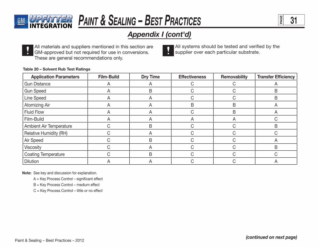
Paint & Sealing – Best Practices – 2012
Paint & Sealing – BeSt PracticeS 31PAG
E
(continued on next page)
Appendix I (cont'd)
All materials and suppliers mentioned in this section are GM-approved but not required for use in conversions. These are general recommendations only.
All systems should be tested and verified by the supplier over each particular substrate.
Application Parameters Film-Build Dry Time Effectiveness Removability Transfer EfficiencyGun Distance A A C C A
Gun Speed A B C C B
Line Speed A A C C B
Atomizing Air A A B B A
Fluid Flow A A C B A
Film-Build A A A A C
Ambient Air Temperature C B C C B
Relative Humidity (RH) C A C C C
Air Speed C B C C A
Viscosity C A C C B
Coating Temperature C B C C C
Dilution A A C C A
Table 20 – Solvent Rub Test Ratings
Note: See key and discussion for explanation.
A = Key Process Control – significant effect
B = Key Process Control – medium effect
C = Key Process Control – little or no effect
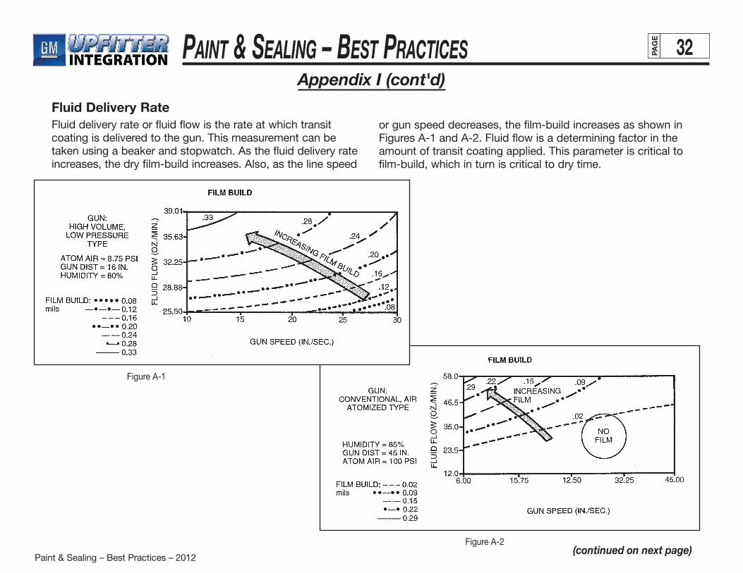
Paint & Sealing – Best Practices – 2012
Paint & Sealing – BeSt PracticeS 32PAG
E
(continued on next page)
Appendix I (cont'd)
Fluid Delivery RateFluid delivery rate or fluid flow is the rate at which transit coating is delivered to the gun. This measurement can be taken using a beaker and stopwatch. As the fluid delivery rate increases, the dry film-build increases. Also, as the line speed
or gun speed decreases, the film-build increases as shown in Figures A-1 and A-2. Fluid flow is a determining factor in the amount of transit coating applied. This parameter is critical to film-build, which in turn is critical to dry time.
Figure A-2
Figure A-1
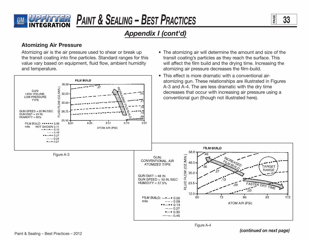
Paint & Sealing – Best Practices – 2012
Paint & Sealing – BeSt PracticeS 33PAG
E
(continued on next page)
Appendix I (cont'd)
Atomizing Air PressureAtomizing air is the air pressure used to shear or break up the transit coating into fine particles. Standard ranges for this value vary based on equipment, fluid flow, ambient humidity and temperature.
• Theatomizingairwilldeterminetheamountandsizeofthetransit coating’s particles as they reach the surface. This will affect the film build and the drying time. Increasing the atomizing air pressure decreases the film-build.
• Thiseffectismoredramaticwithaconventionalair-atomizing gun. These relationships are illustrated in Figures A-3 and A-4. The are less dramatic with the dry time decreases that occur with increasing air pressure using a conventional gun (though not illustrated here).
Figure A-4
Figure A-3
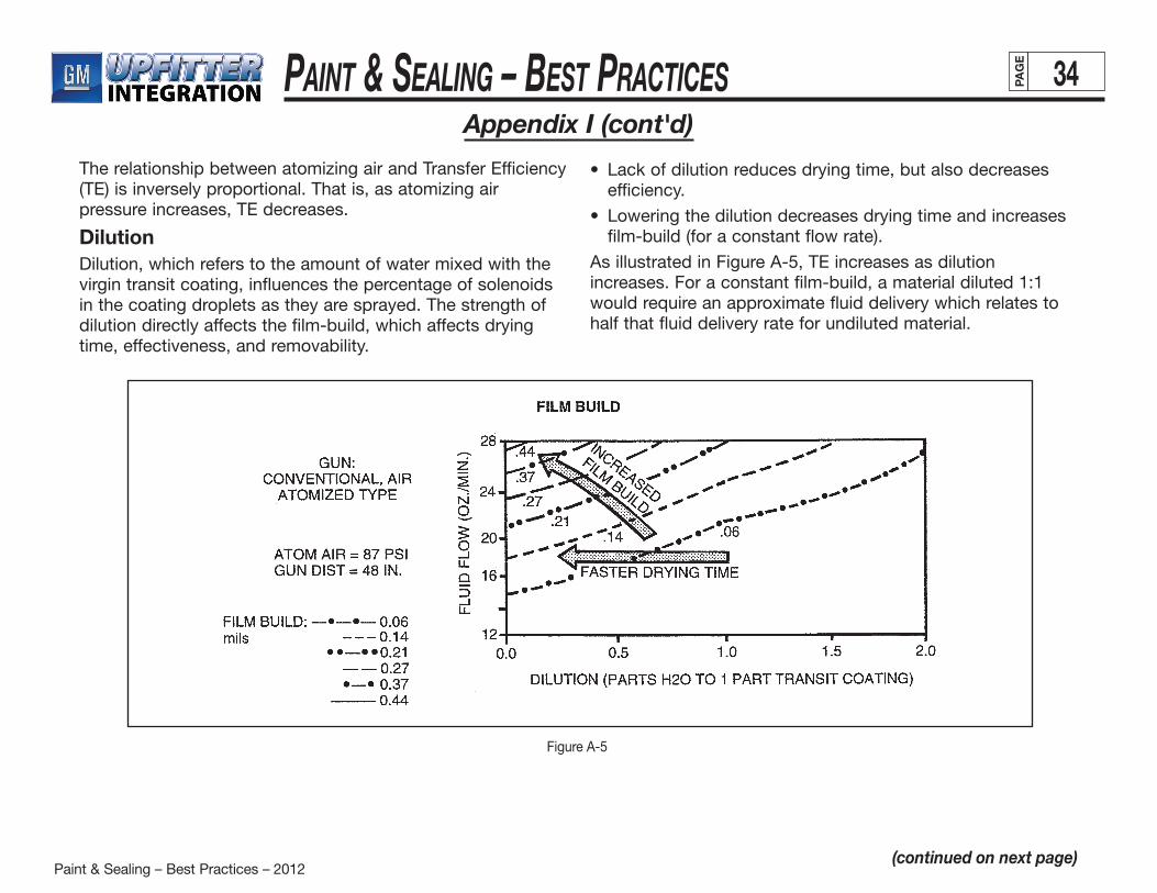
Paint & Sealing – Best Practices – 2012
Paint & Sealing – BeSt PracticeS 34PAG
E
Appendix I (cont'd)
Figure A-5
(continued on next page)
The relationship between atomizing air and Transfer Efficiency (TE) is inversely proportional. That is, as atomizing air pressure increases, TE decreases.
DilutionDilution, which refers to the amount of water mixed with the virgin transit coating, influences the percentage of solenoids in the coating droplets as they are sprayed. The strength of dilution directly affects the film-build, which affects dryingtime, effectiveness, and removability.
• Lackofdilutionreducesdryingtime,butalsodecreasesefficiency.
• Loweringthedilutiondecreasesdryingtimeandincreasesfilm-build (for a constant flow rate).
As illustrated in Figure A-5, TE increases as dilution increases. For a constant film-build, a material diluted 1:1 would require an approximate fluid delivery which relates to half that fluid delivery rate for undiluted material.

Paint & Sealing – Best Practices – 2012
Paint & Sealing – BeSt PracticeS 35PAG
E
Appendix I (cont'd)
(continued on next page)
Gun DistanceStandard measurement for all types of equipment is normally from the gun cap face to the target surface.
• Theshorterthedistancefromtheguntothetarget,thegreater the film build. (See Figure A-6.)
• Increasinggundistancereducesdrytime.Thisisbecausewater evaporates more quickly from airborne spray droplets than from the target surface (Figure A-7).
• Gundistancealsoaffectstheamountoftransitcoatingdeposited on the surface. This significantly affects film build, which influences dry time, effectiveness and removability.
• TEandgundistanceareinverselyproportional.
Figure A-7
Figure A-6

Paint & Sealing – Best Practices – 2012
Paint & Sealing – BeSt PracticeS 36PAG
E
Appendix I (cont'd)
(continued on next page)
Relative Gun Tip Speed (Conveyor Speed)Gun speed is the velocity at which the spray gun travels in relationship with the target. Because it is fixed under normal operating conditions, it is less critical than other application parameters. Gun speed is usually determined by the number of jobs per hour, or line speed.
• Slowergun/linespeed(withconstantflowrates)increasesfilm-build.
• Drytimeincreaseswithslowergun/linespeed. The general relationship is shown in Figures A-8 and A-9.
Decreased gun/line speed reduces dry time. This is because less fluid is required to achieve the filmbuild. The lower the flow rate, the longer the wet material remains in the region of atomization. The longer the material is in the region of atomization, the finer the particles. The larger the total surface area on the fluid being evaporated, the faster the mass transfer process.
Equipment that is fixed should be checked to ensure that it does not vary with use. This parameter should be optimized prior to setting up the equipment.
Figure A-9
Figure A-8
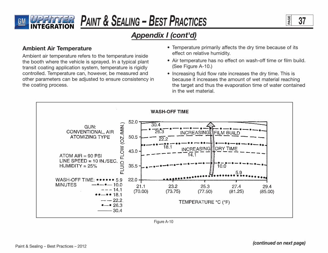
Paint & Sealing – Best Practices – 2012
Paint & Sealing – BeSt PracticeS 37PAG
E
Appendix I (cont'd)
(continued on next page)
Ambient Air TemperatureAmbient air temperature refers to the temperature inside the booth where the vehicle is sprayed. In a typical plant transit coating application system, temperature is rigidly controlled. Temperature can, however, be measured and other parameters can be adjusted to ensure consistency in the coating process.
• Temperatureprimarilyaffectsthedrytimebecauseofitseffect on relative humidity.
• Airtemperaturehasnoeffectonwash-offtimeorfilmbuild.(See Figure A-10.)
• Increasingfluidflowrateincreasesthedrytime.Thisisbecause it increases the amount of wet material reaching the target and thus the evaporation time of water contained in the wet material.
Figure A-10
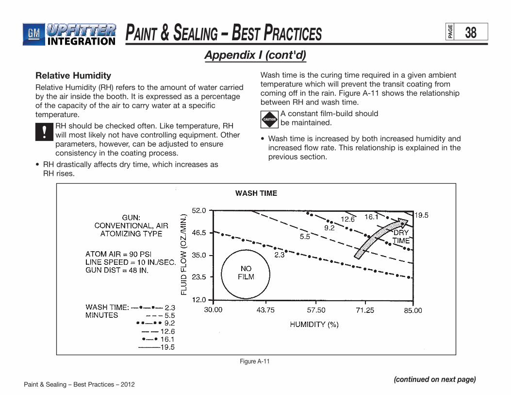
Paint & Sealing – Best Practices – 2012
Paint & Sealing – BeSt PracticeS 38PAG
E
Appendix I (cont'd)
(continued on next page)
Figure A-11
Relative HumidityRelative Humidity (RH) refers to the amount of water carried by the air inside the booth. It is expressed as a percentage of the capacity of the air to carry water at a specific temperature.
RH should be checked often. Like temperature, RH will most likely not have controlling equipment. Other parameters, however, can be adjusted to ensure consistency in the coating process.
• RHdrasticallyaffectsdrytime,whichincreasesas RH rises.
Wash time is the curing time required in a given ambient temperature which will prevent the transit coating from coming off in the rain. Figure A-11 shows the relationship between RH and wash time.
A constant film-build should be maintained.
• Washtimeisincreasedbybothincreasedhumidityandincreased flow rate. This relationship is explained in the previous section.
CAUTION
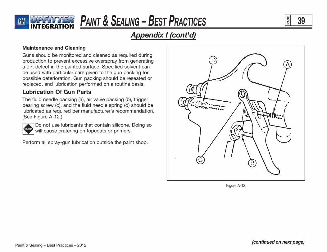
Paint & Sealing – Best Practices – 2012
Paint & Sealing – BeSt PracticeS 39PAG
E
Appendix I (cont'd)
(continued on next page)
Maintenance and CleaningGuns should be monitored and cleaned as required during production to prevent excessive overspray from generating a dirt defect in the painted surface. Specified solvent can be used with particular care given to the gun packing for possible deterioration. Gun packing should be reseated or replaced, and lubrication performed on a routine basis.
Lubrication Of Gun PartsThe fluid needle packing (a), air valve packing (b), trigger bearing screw (c), and the fluid needle spring (d) should be lubricated as required per manufacturer’s recommendation. (See Figure A-12.)
Do not use lubricants that contain silicone. Doing so will cause cratering on topcoats or primers.
Perform all spray-gun lubrication outside the paint shop.
CAUTION
Figure A-12
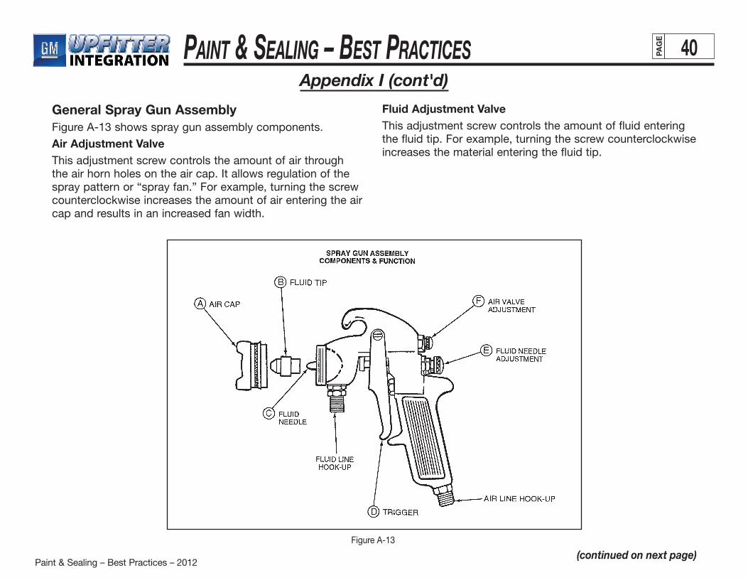
Paint & Sealing – Best Practices – 2012
Paint & Sealing – BeSt PracticeS 40PAG
E
Appendix I (cont'd)
(continued on next page)
General Spray Gun AssemblyFigure A-13 shows spray gun assembly components.
Air Adjustment ValveThis adjustment screw controls the amount of air through the air horn holes on the air cap. It allows regulation of the spray pattern or “spray fan.” For example, turning the screw counterclockwise increases the amount of air entering the air cap and results in an increased fan width.
Fluid Adjustment ValveThis adjustment screw controls the amount of fluid entering the fluid tip. For example, turning the screw counterclockwise increases the material entering the fluid tip.
Figure A-13
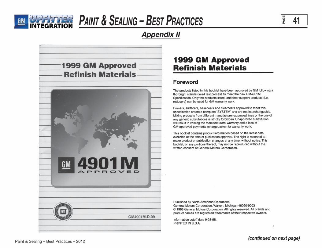
Paint & Sealing – Best Practices – 2012
Paint & Sealing – BeSt PracticeS 41PAG
E
Appendix II
(continued on next page)
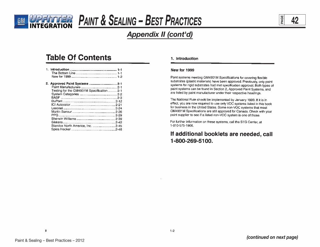
Paint & Sealing – Best Practices – 2012
Paint & Sealing – BeSt PracticeS 42PAG
E
Appendix II (cont'd)
(continued on next page)

Paint & Sealing – Best Practices – 2012
Paint & Sealing – BeSt PracticeS 43PAG
E
Appendix II (cont'd)
(continued on next page)
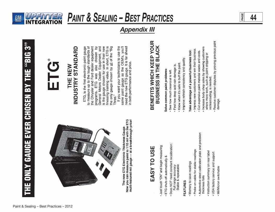
Paint & Sealing – Best Practices – 2012
Paint & Sealing – BeSt PracticeS 44PAG
E
Appendix III