Embed Size (px)
Citation preview
OPERATION MANUAL &
PARTS LIST
CHENG DAY MACHINERY WORKS CO., LTD.
□ □ TUAH-(D)-100 □ SUBH-(D)-200 □ TUBH-(D)-200 □ SUCH-(D)-300 □ TUCH-(D)-300 □ SUDH-(D)-500 □ TUDH-(D)-500 □ SUEH-(D)-750 □ TUEH-(D)-750 □ SUFH-(D)-1000 □ TUFH-(D)-1000 □ SUFI-(D)-1500 □ TUFI-(D)-1500
SERIES:
ELECTRIC WIRE ROPE HOIST
1
SAFETY-IMPORTANT The use of any hoist and trolley presents some risk of personal injury or property damage. That risk is greatly increased if proper instructions and warnings are not followed. Before using this hoist, each user should become thoroughly familiar with all warnings, instructions and recommendations herein.
THIS SYMBOL POINTS OUT IMPORTANT SAFETY INSTRUCTIONS WHICH IF NOT FOLLOWED COULD ENDANGER THE PERSONAL SAFETY AND/OR PROPERTY OF YOURSELF AND OTHERS. READ AND FOLLOW ALL INSTRUCTIONS IN THIS MANUAL AND ANY PROVIDED WITH THE EQUIPMENT BEFORE ATTEMPTING TO OPERATE YOUR "BLACK BEAR" ELECTRIC WIRE ROPE HOIST.
2
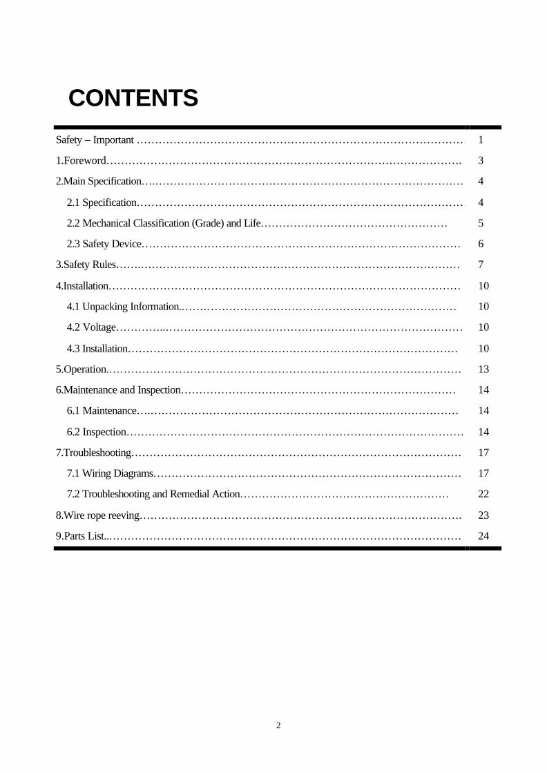
CONTENTS
Safety – Important … … … … … … … … … … … … … … … … … … … … … … … … … … … … … … 1
1.Foreword… … … … … … … … … … … … … … … … … … … … … … … … … … … … … … … … . 3
2.Main Specification… .… … … … … … … … … … … … … … … … … … … … … … … … … … … … 4
2.1 Specification… … … … … … … … … … … … … … … … … … … … … … … … … … … … … … 4
2.2 Mechanical Classification (Grade) and Life… … … … … … … … … … … … … … … … … 5
2.3 Safety Device… … … … … … … … … … … … … … … … … … … … … … … … … … … … … 6
3.Safety Rules… … .… … … … … … … … … … … … … … … … … … … … … … … … … … … … … 7
4.Installation… … … … … … … … … … … … … … … … … … … … … … … … … … … … … … … … 10
4.1 Unpacking Information.… … … … … … … … … … … … … … … … … … … … … … … … … 10
4.2 Voltage… … … … ..… … … … … … … … … … … … … … … … … … … … … … … … … … … 10
4.3 Installation… … … … … … … … … … … … … … … … … … … … … … … … … … … … … … 10
5.Operation.… … … … … … … … … … … … … … … … … … … … … … … … … … … … … … … … 13
6.Maintenance and Inspection… … … … … … … … … … … … … … … … … … … … … … … … … 14
6.1 Maintenance… .… … … … … … … … … … … … … … … … … … … … … … … … … … … … 14
6.2 Inspection… … … … … … … … … … … … … … … … … … … … … … … … … … … … … … … 14
7.Troubleshooting… … … … … … … … … … … … … … … … … … … … … … … … … … … … … … 17
7.1 Wiring Diagrams… … … … … … … … … … … … … … … … … … … … … … … … … … … … 17
7.2 Troubleshooting and Remedial Action… … … … … … … … … … … … … … … … … … … 22
8.Wire rope reeving… … … … … … … … … … … … … … … … … … … … … … … … … … … … … . 23
9.Parts List..… … … … … … … … … … … … … … … … … … … … … … … … … … … … … … … … 24
3
1. FOREWORD
This manual contains important information to help you properly install, operate and maintain the Black
Bear electric wire rope hoist for maximum performance, economy and safety. Please study its contents
thoroughly before putting the electric wire rope hoist into operation. By practicing correct operation, procedures
and by carrying out the preventative maintenance recommendations, you will be assured of dependable service.
In order to help us to supply correct spare parts quickly, please always specify,
(1) Hoist model
(2) Serial number
(3) Part number, plus the description.
We trust that you will find this "Black Bear" electric wire rope hoist will give you many years of satisfactory
service.
Should you have any queries, please contact:
(Please ask for a company's stamp from your local agent)
4
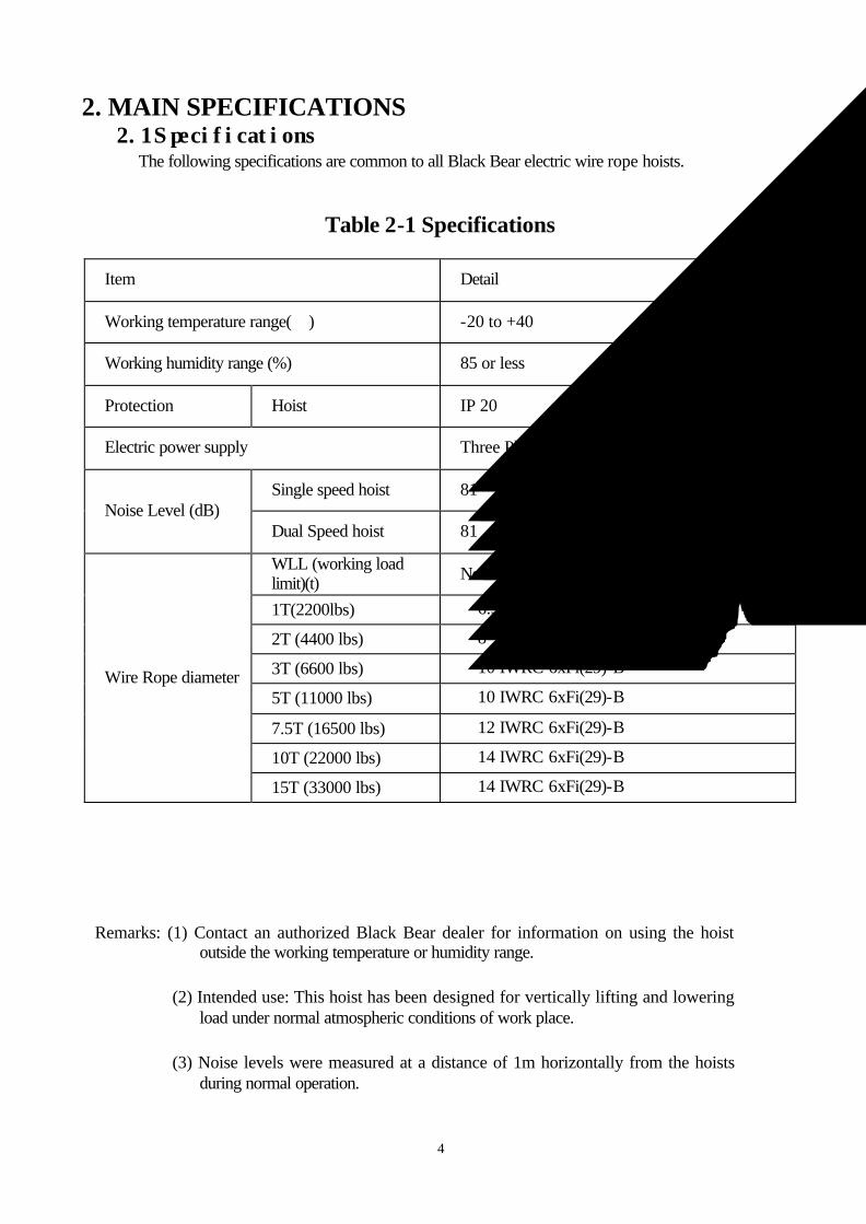
2. MAIN SPECIFICATIONS 2.1 Specifications The following specifications are common to all Black Bear electric wire rope hoists.
Table 2-1 Specifications
Item Detail
Working temperature range(℃) -20 to +40
Working humidity range (%) 85 or less
Protection Hoist IP 20
Electric power supply Three Phase, 200~600V, 50/60 Hz
Single speed hoist 81 Noise Level (dB)
Dual Speed hoist 81
WLL (working load limit)(t) Nominal diameter (mm)
1T(2200lbs) φ6.3 6x37-A
2T (4400 lbs) φ8 6x37-A
3T (6600 lbs) φ10 IWRC 6xFi(29)-B
5T (11000 lbs) φ10 IWRC 6xFi(29)-B
7.5T (16500 lbs) φ12 IWRC 6xFi(29)-B
10T (22000 lbs) φ14 IWRC 6xFi(29)-B
Wire Rope diameter
15T (33000 lbs) φ14 IWRC 6xFi(29)-B
Remarks: (1) Contact an authorized Black Bear dealer for information on using the hoist outside the working temperature or humidity range.
(2) Intended use: This hoist has been designed for vertically lifting and lowering load under normal atmospheric conditions of work place.
(3) Noise levels were measured at a distance of 1m horizontally from the hoists during normal operation.
5
2.2 Mechanical Classification (Grade) and Life
Safety and life for electric wire rope hoists are guaranteed only when the said equipment is
operated in accordance with the prescribed grade.
Black Bear electric wire rope hoists have been designed according to FEM
regulations (FEM 9.511).
Details are provided in Table 2-2.
Average daily operating time and total operating time are determined by load distribution.
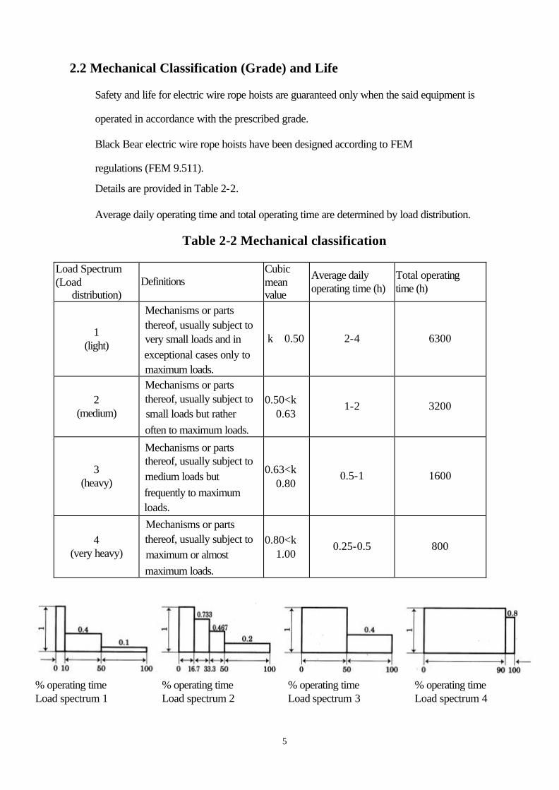
Table 2-2 Mechanical classification
Load Spectrum (Load
distribution) Definitions
Cubic mean value
Average daily operating time (h)
Total operating time (h)
1 (light)
Mechanisms or parts thereof, usually subject to very small loads and in exceptional cases only to maximum loads.
k≦0.50 2-4 6300
2 (medium)
Mechanisms or parts thereof, usually subject to small loads but rather often to maximum loads.
0.50<k≦0.63
1-2 3200
3 (heavy)
Mechanisms or parts thereof, usually subject to medium loads but frequently to maximum loads.
0.63<k≦0.80
0.5-1 1600
4 (very heavy)
Mechanisms or parts thereof, usually subject to maximum or almost maximum loads.
0.80<k≦1.00
0.25-0.5 800
% operating time Load spectrum 1
% operating time Load spectrum 2
% operating time Load spectrum 3
% operating time Load spectrum 4
6
2.3 Safety Devices
(1) Motor brake
"AC Electro-Magnetic Brake" is of a unique design in its field. It features simultaneous
motor braking upon switching off power even under full load condition.
(2) Mechanical load brake
The mechanical load brake can hold a full capacity load independent of motor brake.
This brake assures that load does not accelerate while being lowered.
(3) Hook and hook latch
The hook is drop - forged from high tensile steel and heat treated for strength and
toughness. The button hook is capable of 360°swivel and fitted with safety latch to
ensure safe lifting.
(4) Limit Switches
Upper and lower limit switches are fitted for switching off power automatically in case
of over lifting or over lowering.
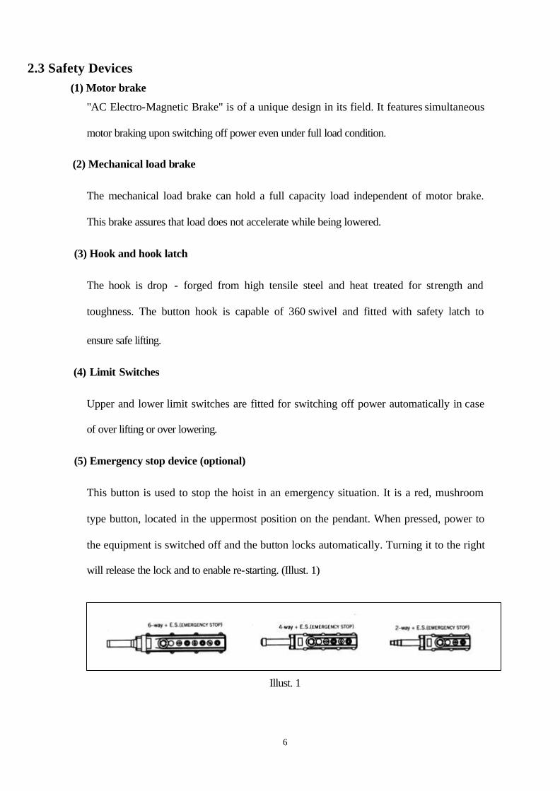
(5) Emergency stop device (optional)
This button is used to stop the hoist in an emergency situation. It is a red, mushroom
type button, located in the uppermost position on the pendant. When pressed, power to
the equipment is switched off and the button locks automatically. Turning it to the right
will release the lock and to enable re-starting. (Illust. 1)
Illust. 1
7
3. SAFETY RULES
(1) Only the trained personnel are allowed to operate the hoist.
(2)
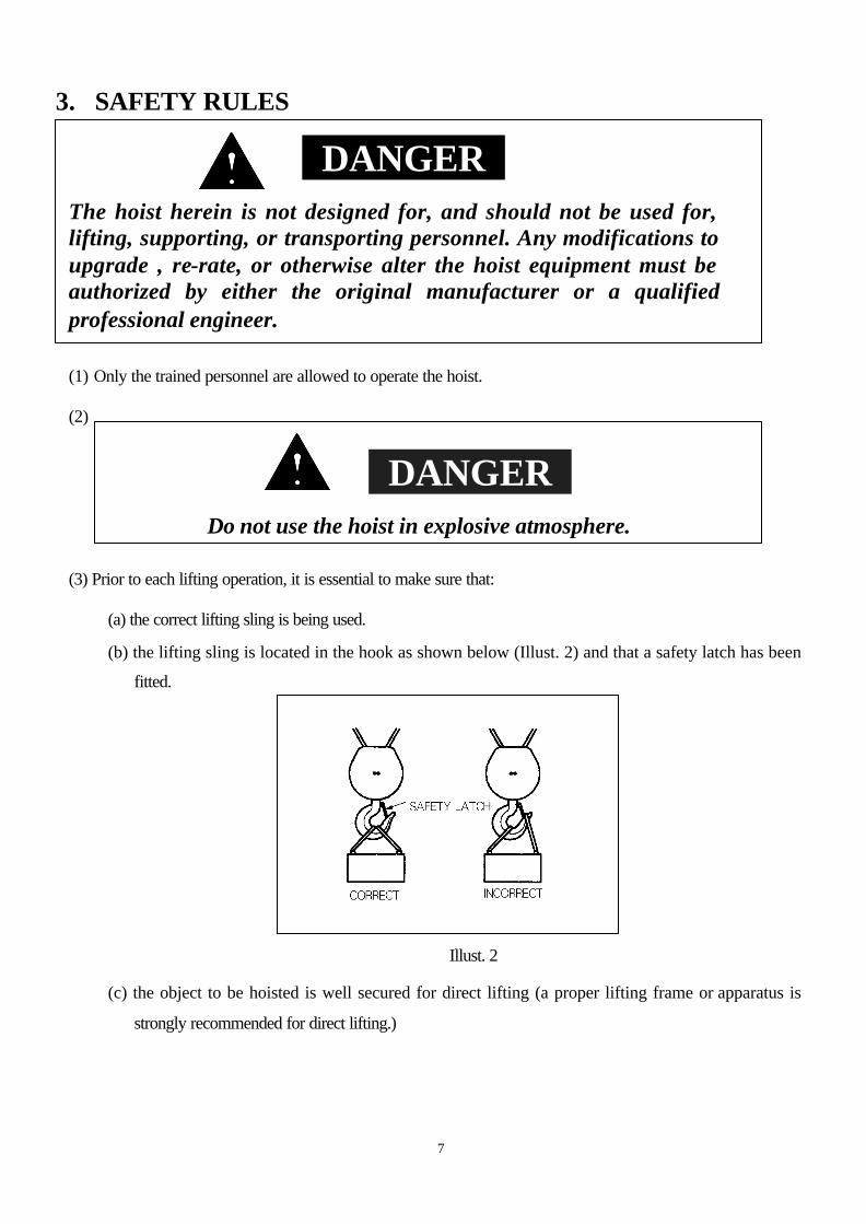
(3) Prior to each lifting operation, it is essential to make sure that:
(a) the correct lifting sling is being used.
(b) the lifting sling is located in the hook as shown below (Illust. 2) and that a safety latch has been
fitted.
Illust. 2
(c) the object to be hoisted is well secured for direct lifting (a proper lifting frame or apparatus is
strongly recommended for direct lifting.)
DANGER The hoist herein is not designed for, and should not be used for, lifting, supporting, or transporting personnel. Any modifications to upgrade , re-rate, or otherwise alter the hoist equipment must be authorized by either the original manufacturer or a qualified professional engineer.
DANGER
Do not use the hoist in explosive atmosphere.
8
(4) Firm and steady button operation is required, never push the button switch
intermittently.
(5) Always avoid excessive inching operation.
(6) Always make sure the hoist motor completely stops before reversing.
(7) Always leave the pendant button switch cable and bottom hook vertically static after
completion of operation, never leave them at any position, which may allow them
swing or slip.
(8) Sling must be applied to load evenly and centrally to ensure correct balance. Never
lift any object which is insecure or out of balance.
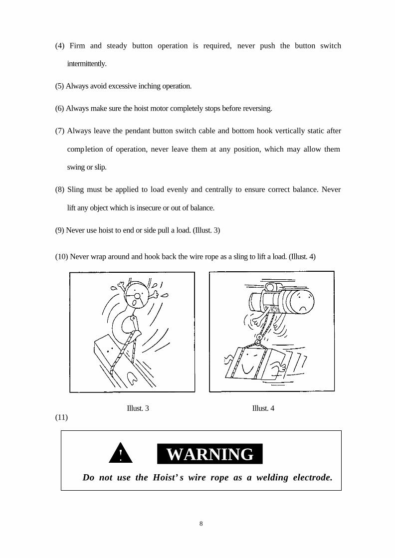
(9) Never use hoist to end or side pull a load. (Illust. 3)
(10) Never wrap around and hook back the wire rope as a sling to lift a load. (Illust. 4)
Illust. 3 Illust. 4 (11)
WARNING Do not use the Hoist’s wire rope as a welding electrode.
9
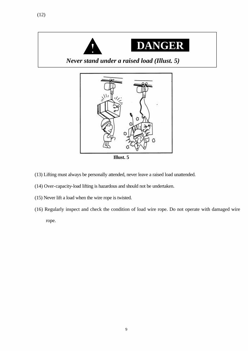
(12)
Illust. 5
(13) Lifting must always be personally attended, never leave a raised load unattended.
(14) Over-capacity-load lifting is hazardous and should not be undertaken.
(15) Never lift a load when the wire rope is twisted.
(16) Regularly inspect and check the condition of load wire rope. Do not operate with damaged wire
rope.
DANGER Never stand under a raised load (Illust. 5)
10
4. INSTALLATION
4.1 Unpacking Information
After removing the hois t from its packing box, carefully inspect the external condition of the electrical
cables, contactor, gear box and motor casing for damage.
4.2 Voltage
4.3 Installation
CAUTION If power supply deviates from standard by more than ±10%, abnormal operation or damage to the motor may result. It is imperative to ensure correct voltage supply before commencing operation.
WARNING Connection to power supply before installation procedures having been completed is strictly prohibited.
11
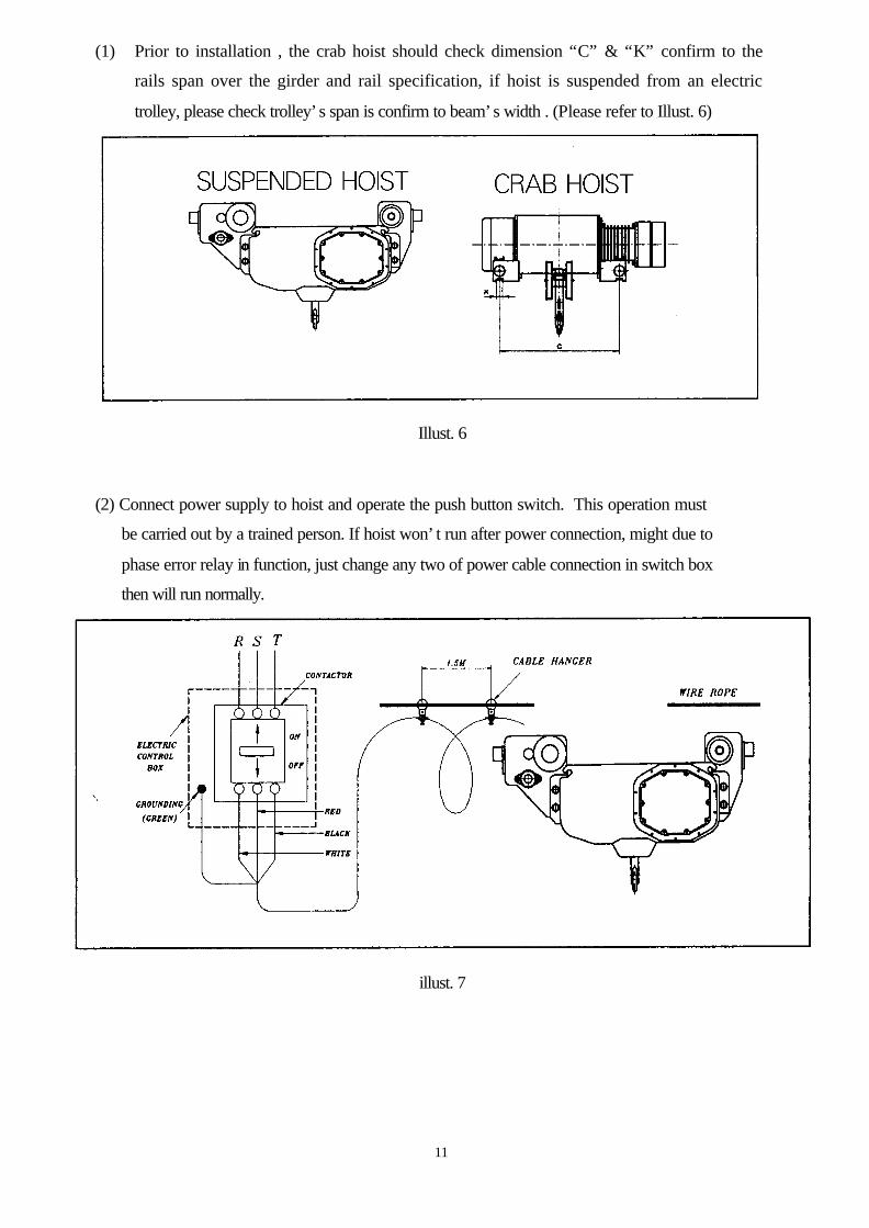
(1) Prior to installation , the crab hoist should check dimension “C” & “K” confirm to the
rails span over the girder and rail specification, if hoist is suspended from an electric
trolley, please check trolley’s span is confirm to beam’s width . (Please refer to Illust. 6)
Illust. 6
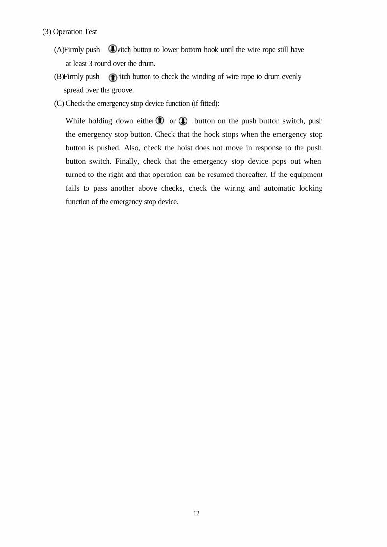
(2) Connect power supply to hoist and operate the push button switch. This operation must
be carried out by a trained person. If hoist won’t run after power connection, might due to
phase error relay in function, just change any two of power cable connection in switch box
then will run normally.
illust. 7
12
(3) Operation Test
(A)Firmly push switch button to lower bottom hook until the wire rope still have
at least 3 round over the drum.
(B)Firmly push switch button to check the winding of wire rope to drum evenly
spread over the groove.
(C) Check the emergency stop device function (if fitted):
While holding down either or button on the push button switch, push
the emergency stop button. Check that the hook stops when the emergency stop
button is pushed. Also, check the hoist does not move in response to the push
button switch. Finally, check that the emergency stop device pops out when
turned to the right and that operation can be resumed thereafter. If the equipment
fails to pass another above checks, check the wiring and automatic locking
function of the emergency stop device.
13
5. OPERATION
After running test and checks have been completed, the hoist will be ready for normal
operation.
(1) The operator must have a clear and unobstructed view of the entire working area before
operating the hoist.
(2) The operator must check that the entire working area is safe and secure before operating the
hoist.
(3) When using the hoist with a motorized trolley, the operator must take care to prevent
excessive load swinging by sympathetic use of the trolley controls.
WARNING Since dealing with heavy loads may involve unexpected danger, all of the "SAFETY RULES" (Ref 3.) must be followed and the operator must be aware of the following points while using the hoist.
14
6. MAINTENANCE AND INSPECTION
6.1 Maintenance
(1) Check the level of gearbox lubricant after first 500 hours of operation, thereafter every 3 months and lubricant accordingly.
Note: We recommend using lubricant oil equivalent to ISO VG460 as table of following annual
inspection.
(2) Always keep the hoist unit dry and never misuse it in a manner likely to reduce its durability.
(3) When it is necessary to keep the unit outdoors, a protective covering should be fitted.
6.2 Inspection
(1) Daily inspection: Before starting daily operation, check the following,
(a) Correct power supply. (b) "Up", "Down" and "Emergency stop" (where fitted) test runs under no load. (c) Correct motor performance. (d) No abnormal or excessive noise. (e) No malfunction of the bottom hook safety latch. (f) Proper function of moving/turning parts, limit switches and brake. (g) The condition of wire rope and winding evenly over the drum. (h) Wire rope out of the bottom block’s wheel groove or not.
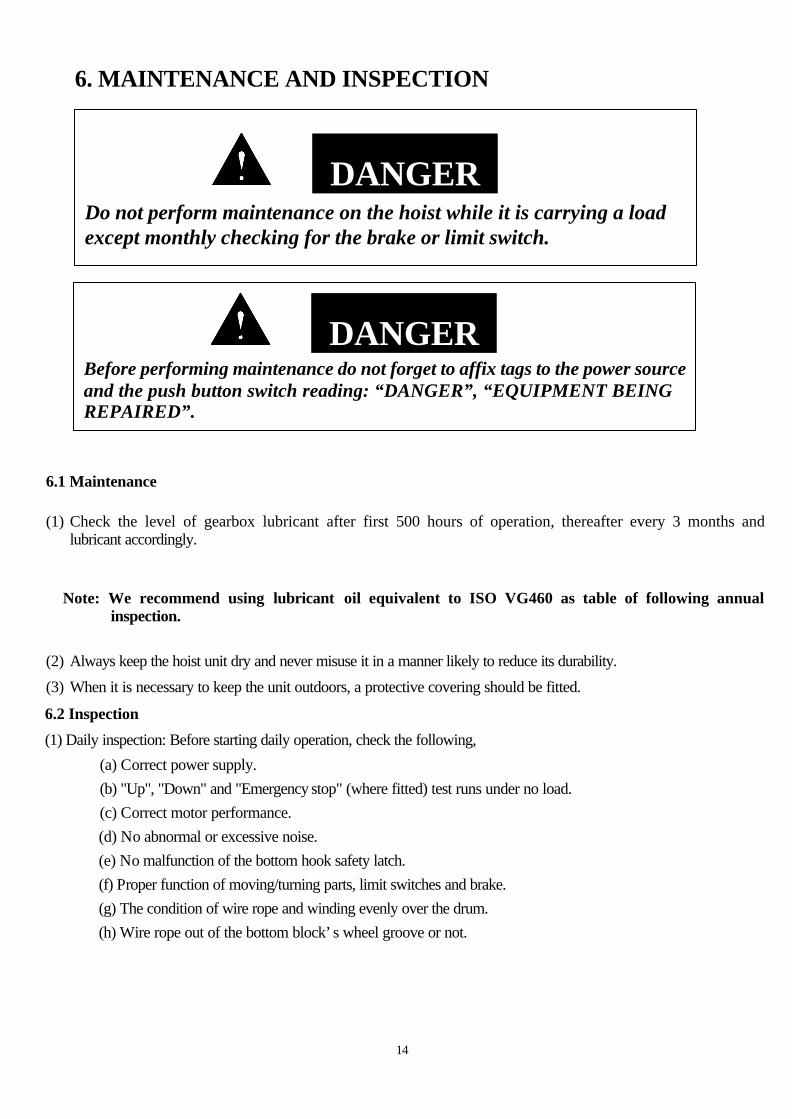
DANGER Do not perform maintenance on the hoist while it is carrying a load except monthly checking for the brake or limit switch.
DANGER
Before performing maintenance do not forget to affix tags to the power source and the push button switch reading: “DANGER”, “EQUIPMENT BEING REPAIRED”.
15
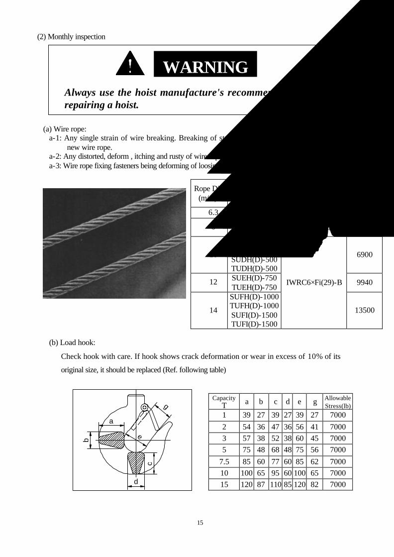
(2) Monthly inspection
(a) Wire rope: a-1: Any single strain of wire breaking. Breaking of strains more than 10% should replace
new wire rope. a-2: Any distorted, deform , itching and rusty of wire rope. a-3: Wire rope fixing fasteners being deforming of loosing.
Rope Dia. (m/m)d
Model Being Used
Construction Specified Breaking Load(lb)
φ6.3 TUAH(D)-100 (6×37)-A 2150
φ8 SUBH(D)-200 TUBH(D)-200 (6×37)-A 3470
φ10
SUCH(D)-300 TUCH(D)-300 SUDH(D)-500 TUDH(D)-500
6900
φ12 SUEH(D)-750 TUEH(D)-750
9940
φ14
SUFH(D)-1000 TUFH(D)-1000 SUFI(D)-1500 TUFI(D)-1500
IWRC6×Fi(29)-B
13500
(b) Load hook:
Check hook with care. If hook shows crack deformation or wear in excess of 10% of its
original size, it should be replaced (Ref. following table)
Capacity (T) a b c d e g Allowable
Stress(lb) 1 39 27 39 27 39 27 7000 2 54 36 47 36 56 41 7000 3 57 38 52 38 60 45 7000 5 75 48 68 48 75 56 7000
7.5 85 60 77 60 85 62 7000 10 100 65 95 60 100 65 7000 15 120 87 110 85 120 82 7000
WARNING
Always use the hoist manufacture's recommended parts when repairing a hoist.
a
b
d
c
e
g
16
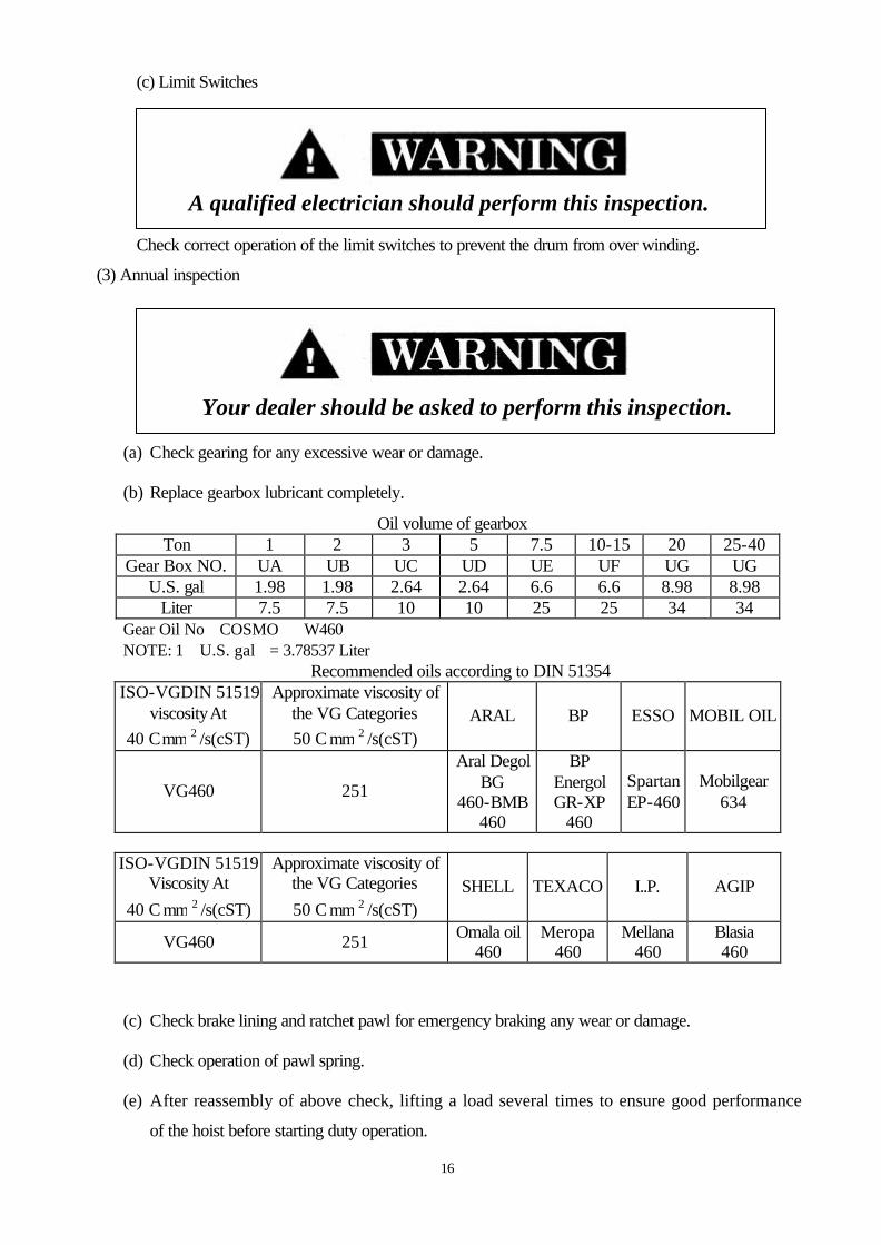
(c) Limit Switches
Check correct operation of the limit switches to prevent the drum from over winding.
(3) Annual inspection
(a) Check gearing for any excessive wear or damage.
(b) Replace gearbox lubricant completely.
Oil volume of gearbox Ton 1 2 3 5 7.5 10-15 20 25-40
Gear Box NO. UA UB UC UD UE UF UG UG U.S. gal 1.98 1.98 2.64 2.64 6.6 6.6 8.98 8.98
Liter 7.5 7.5 10 10 25 25 34 34 Gear Oil No:COSMO #W460 NOTE: 1(U.S. gal)= 3.78537 Liter
Recommended oils according to DIN 51354 ISO-VGDIN 51519
viscosity At 40°C 2mm /s(cST)
Approximate viscosity of the VG Categories 50°C 2mm /s(cST)
ARAL BP ESSO MOBIL OIL
VG460 251
Aral Degol BG
460-BMB 460
BP Energol GR-XP
460
Spartan EP-460
Mobilgear 634
ISO-VGDIN 51519 Viscosity At
40°C 2mm /s(cST)
Approximate viscosity of the VG Categories 50°C 2mm /s(cST)
SHELL TEXACO I..P. AGIP
VG460 251 Omala oil 460
Meropa 460
Mellana 460
Blasia 460
(c) Check brake lining and ratchet pawl for emergency braking any wear or damage.
(d) Check operation of pawl spring.
(e) After reassembly of above check, lifting a load several times to ensure good performance
of the hoist before starting duty operation.
A qualified electrician should perform this inspection.
Your dealer should be asked to perform this inspection.
17
7. TROUBLESHOOTING
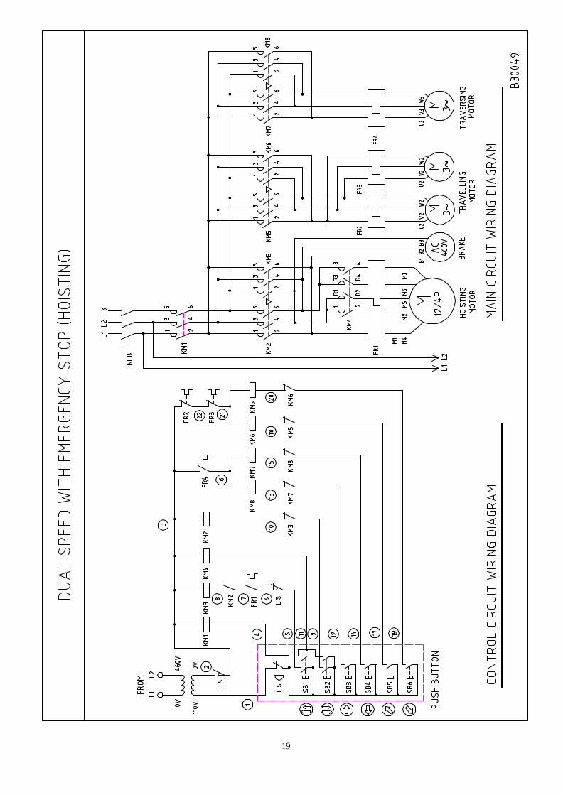
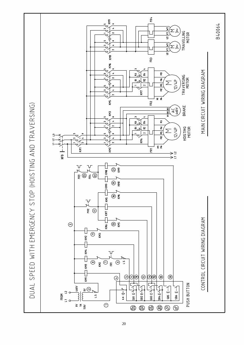
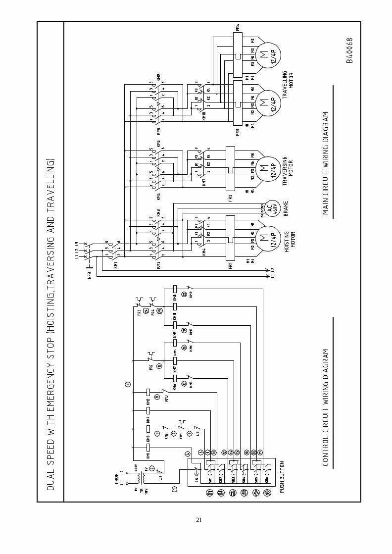
7.1 Wiring Diagrams
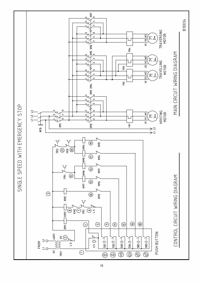
(1) Single Speed Wiring Diagram… … … … … … … … … … … … … … … … … … ..17
(2) Dual Speed Wiring Diagram (Hoisting) … … … … … … … … … … … … … … ..18
(3) Dual Speed Wiring Diagram (Hoisting, Traversing) .… … … … … … … … … ..19
(4) Dual Speed Wiring Diagram (Hoisting, Traversing, Traveling) … … … … … ..20
7.1.1 The above models are available in the following specification: (a) 3-Phase
(b) 50 or 60 Hertz
(c) Single voltage
Voltage Hertz Single Voltage
50 Hz
60 Hz
220 to
600
18
19
20
21
22
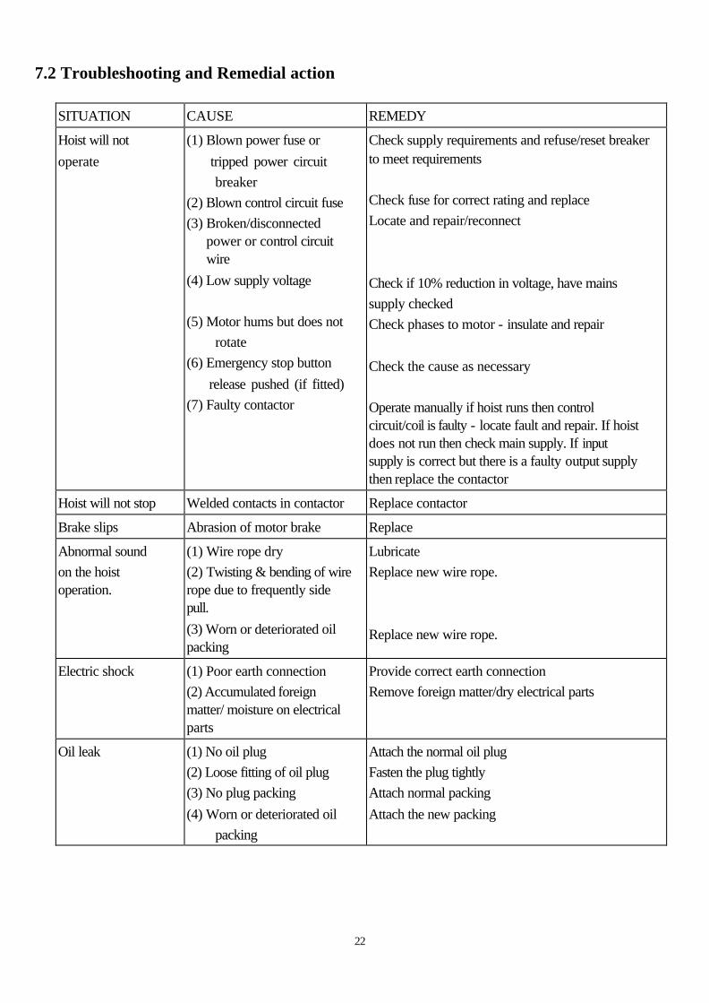
7.2 Troubleshooting and Remedial action
SITUATION CAUSE REMEDY
Hoist will not operate
(1) Blown power fuse or tripped power circuit breaker (2) Blown control circuit fuse (3) Broken/disconnected
power or control circuit wire
(4) Low supply voltage (5) Motor hums but does not rotate (6) Emergency stop button release pushed (if fitted) (7) Faulty contactor
Check supply requirements and refuse/reset breaker to meet requirements Check fuse for correct rating and replace Locate and repair/reconnect Check if 10% reduction in voltage, have mains supply checked Check phases to motor - insulate and repair Check the cause as necessary Operate manually if hoist runs then control circuit/coil is faulty - locate fault and repair. If hoist does not run then check main supply. If input supply is correct but there is a faulty output supply then replace the contactor
Hoist will not stop Welded contacts in contactor Replace contactor
Brake slips Abrasion of motor brake Replace
Abnormal sound on the hoist operation.
(1) Wire rope dry (2) Twisting & bending of wire rope due to frequently side pull. (3) Worn or deteriorated oil packing
Lubricate Replace new wire rope. Replace new wire rope.
Electric shock (1) Poor earth connection (2) Accumulated foreign matter/ moisture on electrical parts
Provide correct earth connection Remove foreign matter/dry electrical parts
Oil leak (1) No oil plug (2) Loose fitting of oil plug (3) No plug packing (4) Worn or deteriorated oil packing
Attach the normal oil plug Fasten the plug tightly Attach normal packing Attach the new packing