Embed Size (px)
Citation preview

~~~11 ELECTRIC POWER a=1-1.:;;, RESEARCH INSTITUTE
MRP Materials Reliability Program ___________ MRP 2017-036
December 18, 2017
U.S. Nuclear Regulatory Commission One White Flint North Mail Stop: 0-12-D2 11555 Rockville Pike Rockville, Maryland 20852-2738
SUBJECT: TRANSMITTAL OF REVISION 1 TO EPRI TECHNICAL REPORTS MRP-175 AND MRP-211' (TAC NO. ME0680)
Reference:· 1. Letter from Joseph Holonich (NRC) to Brian Burgos (EPRI), dated November 29, 2017 [ML17307A156]
In response to NRC's November 29, 2017 letter (Reference 1) requesting that EPRI provide copies of reports to support NRC review of EPRI Report 3002005349, "Materials Reliability Program: Pressurized Water Reactor Internals Inspection and Evaluation Guidelines (MRP-227-Rev. 1)" we are forwarding for information only two copies of the following two (2) documents:
l) Materials Reliability Program: PWR [Pressurized Water Reactor] Internals Material Aging Degradation Mechanism Screening and Threshold Values (MRP-175, Revision 1). EPRI, Palo Alto, CA: 2017. 3002010268.; 2) Materials Reliability Program: PWR Internals Age-Related Material Properties, Degradation Mechanisms, Models, and Basis Data-State of Knowledge (MRP-211, Revision 1). EPRI, Palo Alto, CA: 2017. 3002010270.
Also included is an affidavit requesting that this copyrighted information be withheld from public disclosure. These documents include the proper markings on them in accordance with 10 CFR 2.390. One (1) redacted copy of each of these reports is also provided herein for inclusion in ADAMS. In addition, enclosed is the MRP-227 Roadmap developed in 2010 for reference and use in reviewing and understanding the development of the MRP-227. This was originally included in MRP-227-A Appendix B, and provides useful insights into the technical basis supporting the MRP-227 requirements.
If you have any questions, please contact Brian Burgos at 724-610-8559 or Kyle Amberge at 704-595-2039.
Sincerely,
4--~::Ir-M. Hoehn II, Ameren MRP LC. Chair
D---frr-B. Burgos, Program Manager EPRI-MRP
Together ... Shaping the Future of Electricity
PALO ALTO OFFICE
3420 Hillview Avenue, Palo Alto, CA 94304· J 338 USA • 650.855.2000 • Customer Service 800.313.377 4 • www.epri.com

UNITED STATES NUCLEAR REGULATORY COMMISSION
WASHINGTON, D.C. 20555-0001
Brian Burgos MRP Program Manager Electric Power Research Institute 3420 Hillview Avenue Palo Alto, CA 94304
November 29, 2017
SUBJECT: REQUEST FOR REVISION 1 TO MRP-175 AND MRP-211
Dear Mr. Burgos:
From May 23-25, 2017, U.S. Nuclear Regulatory Commission (NRC) staff and representatives from the Electric Power Research Institute (EPRI) and industry attended a meeting on materials exchange (Agencywide Documents Access and Management System (ADAMS) Accession No. ML 17142A011 ). At that meeting, EPRI reported that the following documents were being revised.
"Materials Reliability Program: PWR [Pressurized Water Reactor] Internals Material Aging Degradation Mechanism Screening and Threshold Values" (MRP-175, Revision 1). EPRI, Palo Alto, CA: 2017. 3002010268.
"Materials Reliability Program: PWR Internals Age-Related Material Properties, Degradation Mechanisms, Models, and Basis Data-State of Knowledge" (MRP-211, Revision 1). EPRI, Palo Alto, CA: 2017. 3002010270.
It is the NRC staff's understanding that the revisions to these documents are now complete. Therefore, the NRC staff requests that EPRI submit MRP-175, Revision 1, and MRP-211, Revision 1, to the NRC. These updated reports are expected to support the subsequent license renewal implementation of MRP-227, Revision 2, "Materials Reliability Program: Pressurized Water Reactor Internals Inspection and Evaluation Guidelines" scheduled for completion in calendar year 2020.
If you have any questions, please do not hesitate to contact me at (301) 415-7297 or by electronic mail at [email protected].
DocketNo.99902021
Sincerely,
~ ('_,,/,-;,<::.__ {}11 U~~ f'::.LN1\A'/ (C!t'-
~oseph(~nich, Senior Project Manager Licensing Processes Branch Division of Licensing Projects Office of Nuclear Reactor Regulation
ML17307Al56

r- SUBJECT: REQUEST FOR REVISION 1 TO MRP-175 AND MRP-211 DATED: NOVEMBER 29, 2017
DISTRIBUTION: PUBLIC RidsNrrDeEvib PLPB R/F
DMorey RidsNrrDlp RidsNrrLADHarrison
RidsNrrDlpPlpb JHolonich SRuffin
RidsACRS_MailCTR JPoehler AHiser
ADAMS Accession No.: ML 17307A156; *concurrence via e-mail NRR-106 OFFICE DLP/PLPB/PM DLP/PLPB/LA* DLP/PLPB/BC DLP/PLPB/PM NAME JHolonich DHarrison DMorev (BBenney for) JHolonich DATE 11/27/2017 11/14/2017 11/28/2017 11/29/2017
OFFICIAL RECORD COPY

:i., I • 'I·
I '--
\
[DOCUMENT PARTIALLY REDACTED]
Materials Reliability Program: PWR Internals Age-Related Material Properties, Degradation Mechanisms, Models, and Basis Data-State of Knowledge {MRP-211 , Revision 1)
3002010270
Final Report, October 2017
EPRI Project Manager K. Amberge
All or a portion of the requirements of the EPRI Nuclear Quality Assurance Program apply to this product.
YES ~
ELECTRIC POWER RESEARCH INSTITUTE 3420 Hillview Avenue, Palo Alto, California 94304-1338 • PO Box 10412, Palo Alto, California 94303-0813 • USA
800.313.3774, 650.855.2121 • [email protected] • www.epri.com

I· I
DISCLAIMER OF WARRANTIES AND LIMITATION OF LIABILITIES
THIS DOCUMENT WAS PREPARED BY THE ORGANIZATIONS NAMED BELOW AS AN ACCOUNT OF WORK SPONSORED OR COSPONSORED BY THE ELECTRIC POWER RESEARCH INSTITUTE, INC. (EPRI). NEITHER EPRI, ANY MEMBER OF EPRI, ANY COSPONSOR, THE ORGANIZATIONS BELOW, NOR ANY PERSON ACTING ON BEHALF OF ANY OF THEM:
(A) MAKES ANY WARRANTY OR REPRESENTATION WHATSOEVER, EXPRESS OR IMPLIED, (I) WITH RESPECT TO THE USE OF ANY INFORMATION, APPARATUS, METHOD, PROCESS, OR SIMILAR ITEM DISCLOSED IN THIS DOCUMENT, INCLUDING MERCHANTABILITY AND FITNESS FOR A PARTICULAR PURPOSE, OR (II) THAT SUCH USE DOES NOT INFRINGE ON OR INTERFERE WITH PRIVATELY OWNED RIGHTS, INCLUDING ANY PARTY'S INTELLECTUAL PROPERTY, OR (Ill) THAT THIS DOCUMENT IS SUITABLE TO ANY PARTICULAR USER'S CIRCUMSTANCE; OR
(B) ASSUMES RESPONSIBILITY FOR ANY DAMAGES OR OTHER LIABILITY WHATSOEVER (INCLUDING ANY CONSEQUENTIAL DAMAGES, EVEN IF EPRI OR ANY EPRI REPRESENTATIVE HAS BEEN ADVISED OF THE POSSIBILITY OF SUCH DAMAGES) RES UL TING FROM YOUR SELECTION OR USE OF THIS DOCUMENT OR ANY INFORMATION, APPARATUS, METHOD, PROCESS, OR SIMILAR ITEM DISCLOSED IN THIS DOCUMENT.
REFERENCE HEREIN TO ANY SPECIFIC COMMERCIAL PRODUCT, PROCESS, OR SERVICE BY ITS TRADE NAME, TRADEMARK, MANUFACTURER, OR OTHERWISE, DOES NOT NECESSARILY CONSTITUTE OR IMPLY ITS ENDORSEMENT, RECOMMENDATION, OR FAVORING BY EPRI.
THE FOLLOWING ORGANIZATIONS, UNDER CONTRACT TO EPRI, PREPARED THIS REPORT:
AREVA Inc.
AREVA SAS
THE TECHNICAL CONTENTS OF THIS PRODUCT WERE NOT PREPARED IN ACCORDANCE WITH THE EPRI QUALITY PROGRAM MANUAL THAT FULFILLS THE REQUIREMENTS OF 10 CFR 50, APPENDIX B. THI.S PRODUCT IS NOT SUBJECT TO THE REQUIREMENTS OF 10 CFR PART 21.
NOTE
For further information about EPRI, call the EPRI Customer Assistance Center at 800.313.3774 or e-mail [email protected].
Electric Power Research Institute, EPRI, and TOGETHER ... SHAPING THE FUTURE OF ELECTRICITY are registered service marks of the Electric Power Research Institute, Inc.
Copyright© 2017 Electric Power Research Institute, Inc. All rights reserved.
l

\
ACKNOWLEDGMENTS
The following organizations, under contract to the Electric Power Research Institute (EPRI), prepared this report:
AREVA Inc. 3315 Old Forest Road P.O. Box 10935 Lynchburg, VA 24506-0935
Principal Investigators S. Fyfitch S. Davidsaver D. Burak
AREVA SAS Tour AREVA I place Jean Millier 92084 Paris La Defense CEDEX, France
Principal Investigator D. Brimbal
This report describes research sponsored by EPRI.
The authors acknowledge the valuable input, review comments, and report editing from the following core members of the Joint EPRI MRP Reactor Internals Core Team Expert Panel:
J. McKinley, R. Lott, M. Burke, and M. Ickes (Westinghouse)
G. Troyer and R. Hosler (AREVA Inc.)
J. Rashid and N. Capps (SIA, formerly ANA TECH)
P. Efsing (Vattenfall)
F. Sefta and J.P. Massoud (EDF)
G. Gardner (Dominion)
T. Wells (Southern Nuclear)
H. Malikowski (Exelon)
iii

The authors also acknowledge the support and efforts of K. Amberge (Joint EPRI MRP RI Core Team Project Manager), J. Smith, C. Topbasi, and P. Chou (EPRI PSCR Project Managers), T. Natour (AREY A Inc. Project Manager), and M. Paden (Westinghouse Project Manager) in completing this report.
This publication is a corporate document that should be cited in the literature in the following manner:
Materials Reliability Program: PWR Internals Age-Related Material Properties, Degradation Mechanisms, Models, and Basis Data-State of Knowledge (MRP-211, Revision 1). EPRI, Palo Alto, CA: 2017. 3002010270.
IV

PRODUCT DESCRIPTION
Irradiation embrittlement (relative to tensile and fracture toughness properties), irradiationassisted stress corrosion cracking, fatigue, irradiation-enhanced stress relaxation and creep, and void swelling are potential degradation mechanisms that could affect pressurized water reactor (PWR) internals components. This report describes the current state of knowledge, available relevant data, and technical bases for trend model formulations of these mechanisms for longterm functionality evaluations.
Background The framework for implementing an aging management program for PWR internals component items using inspections and flaw tolerance evaluations to manage degradation issues has been developed and is documented in Materials Reliability Program: Framework and Strategies for Managing Aging Effects in PWR Internals (MRP-134) (EPRI, Palo Alto, CA: 2005. 1008203) and Materials Reliability Program: Inspection and Flaw Evaluation Strategies for Managing Aging Effects in PWR Internals (MRP-153) (EPRI, Palo Alto, CA: 2005. 1012082). The important elements of this framework are screening, categorizing, and ranking PWR internals components for susceptibility and significance to age-related degradation mechanisms, and performing engineering analyses and safety assessment of PWR internals components to define a safe and cost-effective aging management in-service inspection and evaluation method and strategy.
This report describes the trend or lower-bound models and the associated technical bases for austenitic stainless steel PWR internals materials for each age-related degradation mechanism considered and used in engineering analyses. Engineering evaluations and assessments will be used to refine the categorization and ranking of aged PWR internals components.
Objectives To assess current knowledge of irradiated material data on age-related degradation mechanisms and to provide state-of-the-art degradation models for engineering analyses of selected PWR internals component items.
Approach An expert panel was assembled to review relevant degradation data and the associated trend or lower-bound models for PWR component items: irradiation embrittlement (relative to tensile and fracture toughness properties), fatigue, irradiation-assisted stress corrosion cracking, void swelling, and irradiation-enhanced stress relaxation/creep.
Results The report provides state-of-the-technology data and recommended degradation models for PWR internals austenitic stainless steel materials for each age-related degradation mechanism considered: irradiation embrittlement (relative to tensile and fracture toughness properties), fatigue, irradiation-assisted stress corrosion cracking, void swelling, and irradiation-enhanced stress relaxation/creep. For each age-related degradation mechanism, an assessment of the data
V

fit to available models was performed by the expert panel and alternative formulations suggested, as appropriate. Recommended models are presented that provide the trend of degradation with the relevant environmental conditions, such as neutron fluence, neutron flux, temperature, and stress. A number of gaps that still remain in the database were identified for potential future actions.
EPRI Perspective The Joint EPRI MRP Reactor Internals Core Planning Team has been conducting studies to develop technical bases to support aging management of PWR internals, with particular attention to utility license renewal commitments. This report provides models that are recommended to be used in engineering evaluations and assessments. These engineering analyses will be performed to refine the screening of PWR internal components in accordance with MRP-134.
Keywords Aging management Degradation mechanism Functionality License renewal PWR internals
VI
' .

ABSTRACT
This report summarizes the current state of knowledge of neutron irradiation-induced property changes in austenitic stainless steels, principally solution-annealed Type 304 and 304L materials, cold-worked and solution-annealed Type 316 and 316L materials, Grades CF3/CF3M and CF8/CF8M cast austenitic stainless steels (CASS), and austenitic stainless steel weld metals (for example, Type 308). Age-related degradation mechanisms addressed in this report include irradiation embrittlement (IE), irradiation-enhanced stress relaxation and creep (ISR/IC), void swelling (VS), irradiation-assisted stress corrosion cracking (IASCC), and fatigue. Age-related degradation models were also evaluated by an expert panel assembled by the Electric Power Research Institute (EPRI) and the Materials Reliability Program (MRP) Joint Reactor Internals Core Planning Team. The suggested models are to be used for modifications to constitutive and trend models (in a revision to MRP-135) and for engineering evaluations and assessments.
It has been clearly demonstrated that the tensile properties, which are one of the indicators ofIE, saturate after a neutron exposure of 10 to 20 dpa (-6.67 x 10²¹ to 1.33 x 10²² n/cm2
, E > 1.0 MeV). All fracture toughness data, which constitute the second indicator of IE, are bounded by a saturated value for KJc of 38 MPa--Jm (34.6 ksi-Yin.) at neutron expo~ures greater than 6.67 x 10²¹ n/cm2
(E > 1.0 Me V), or approximately 10 dpa. Correlations indicate that a greater creep rate occurs for Type 304 SA material than for Type 316 CW material. A cluster-dynamics-based VS model was developed through another EPRI-sponsored project and is recommended for calculation of VS in PWR environments. It is also expected that the cluster dynamics methodology can be used for ISR/IC predictions. The empirical formulation for JSR/IC presented in this report may be used in the interim. The VS model indicates that steady-state swelling rates of approximately 0.1 %/dpa are reasonable for the fluence levels and temperatures expected in PWR internals during subsequent license renewal (SLR). Sufficient test data of extracted PWR internals components and/or materials to adequately evaluate this trend are currently lacking, but there is sufficient confidence to employ the cluster-dynamic modeling while data gaps are addressed.
CASS and austenitic stainless steel welds are also shown to be susceptible to loss of toughness by combined thermal embrittlement and IE, which is shown to depend on the extent of the ferrite phase. A lower bounding curve has been identified.
Although tensile properties appear to saturate by 20 dpa (-1.33 x 10²² n/cm2, E > 1.0 MeV),
laboratory test data indicate that IASCC initiation susceptibility appears to continue to increase with irradiation damage. A lower bound trending model indicates that IASCC crack initiation may not occur in materials irradiated to about 80 dpa (-5.33 x 10²² n/cm2
, E > 1.0 MeV) when loaded to below approximately 35% of irradiated yield strength. An IASCC crack growth model, developed through another EPRI-sponsored project, is recommended for use.
vii

HECTRIC POWER RESEARCH INSTITUTE
EXECUTIVE SUMMARY
Deliverable Number: 3002010270
Product Type: Technical Report
Materials Reliability Program: PWR Internals Age-Related Material Properties, Degradation Mechanisms, Models, and Basis Data-State of Knowledge (MRP-211, Revision 1)
PRIMARY AUDIENCE: PWR Utility Program Engineers
SECONDARY AUDIENCE: PWR Utility ISi Inspection Engineers
KEY RESEARCH QUESTION
The current generation of pressurized water reactor (PWR) units is approaching the end of their respective licensing periods and multiple units have already entered their first period of extended operation (PEO). The nuclear power industry in the United States developed inspection and evaluation (l&E) guidelines for managing aging degradation in reactor vessel internals: MRP-227, Revision 1. Several utilities have now declared their intent to pursue subsequent license renewal (SLR) to extend their licenses beyond the first PEO, which is also beyond the scope 0f MRP-227, Revision 1. To update MRP-227 for SLR, the technical basis documents supporting reactor internals aging management strategy development must also be updated. This report provides the current· state of knowledge of neutron irradiation-induced property changes in austenitic stainless steels, principally solution-annealed Type 304 and 304L materials, coldworked and solution-annealed Type 316 and 316L materials, Grades CF3/CF3M and CF8/CF8M cast austenitic stainless steels (CASS), and austenitic stainless ste.el weld metals (for example, Type 308).
RESEARCH OVERVIEW
A framework for implementing an aging management program for PWR internals component items and using inspections and flaw tolerance evaluations to manage age-related degradation issues was developed over the past 10 years. One of the key elements of this framework is performing engineering analyses and safety assessment of PWR internals components to define a safe and cost'-effective aging management inservice inspection and evaluation method and strategy. This report provides state-of-the-technology data and recommended degradation models for PWR internals austenitic stainless· steel materials for each agerelated degradation mechanism considered: irradiation embrittlement (relative to tensile and fracture toughness properties), fatigue, irradiation-assisted stress corrosion cracking, void swelling, and irradiationenhanced stress relaxation/creep. For each age-related degradation mechanism, an assessment of the data fit to available models was performed by the expert panel and alternative formulations suggested, .as appropriate. Recommended models are presented that provide the trend of degradation with the relevant environmental conditions, such as neutron fluence, neutron flux, temperature, and stress. A number of gaps that still remain in the database were identified for potential future actions.
ix

Et=f21 HECiR!C POWER RESEARCH INSTITUiE
EXECUTIVE SUMMARY
KEY FINDINGS
• This report summarizes the current state of knowledge of neutron irradiation-induced property changes in austenitic stainless steels.
• The following age-related degradation mechanisms were addressed in this report:
o Irradiation embrittlement (IE)
o Irradiation-enhanced stress relaxation and creep (ISR/IC)
o Void swelling (VS)
o Irradiation-assisted stress corrosion cracking (IASCC)
o Fatigue
• It has been clearly demonstrated that the tensile properties, which are one of the indicators of irradiation embrittlement, saturate after a neutron exposure of 10 to 20 dpa (-6.67 x 10²¹ to 1.33 x 10²² n/cm2, E > 1.0 MeV), and representative models are presented.
• All fracture toughness data (the second indicator of irradiation embrittlement) are bounded by a saturated value for KJC of 38 MPa'1m (34.6 ksi'1in.) at neutron exposures greater than 6.67 x
1021· n/cm2 (E > 1.0 MeV), or approximately 10 dpa.
• Thermal stress relaxation appears to saturate in a short time (<100 hours) with a maximum reduction of 10% to 20% of the initial bolt preloads at PWR internals te_mperatures.
• Correlations for irradiation creep strain with effective stress multiplied by the irradiation dose indicate that a greater creep rate occurs for Type 304 SA material than for Type 316 CW materiaL
• A cluster-dynamics-based void swelling model has been developed through another EPRlsponsored project and is recommended for calculation of void swelling in PWR environments; the model indicates that the steady-state swelling rates of 1 %/dpa, which have been of concern, may not be possible for the fluence levels and temperatures potentially obtainable in PWR internals during SLR.
• Although tensile properties appear to saturate by 20 dpa (-1.33 x 10²² n/cm2, E > 1.0 MeV), laboratory test data indicate that susceptibility to IASCC initiation appears to continue to increase with the irradiation damage level; a lower bound trending model indicates that IASCC crack initiation may not occur in materials irradiated to about 80 dpa (-5.33 x 10²² n/cm2, E > 1.0 MeV) when loaded to below approximately 35% of irradiated yield strength.
• An IASCC crack growth model bas been developed through another EPRl-sponsored project and is recommended for use by the expert panel.
• The expert panel recommended applying existing methods for evaluating fatigue life on irradiated materials with a suggested environmental correction in accordance with NUREG/CR-6909, Revision 1, with the caveat that as more data are gathered from testing irradiated materials, this approach may require modification.
WHY THIS MATTERS
MRP-211, Revision 1 provides the current state-of-knowledge with the available relevant data and updates the recommended models to describe the trend of aging degradation for the austenitic stainless steels used in PWR internals with the relevant environmental conditions, such as neutron fluence, neutron flux, temperature, and stress .. The information provided in MRP-211, Revision 1 is to be used in the engineering evaluations and assessments, which is the next step of the process for development of MRP-227 for SLR.
X

EF'l21 fLECTRIC POWER RESEARCH INSllTUiE
HOW TO APPLY RES UL TS
EXECUTIVE SUMMARY
MRP-211, Revision 1 is a technical basis document supporting the development of an MRP-227 revision applicable to SLR. For the development of MRP-227 for SLR, utility, vendor, and EPRI members will use the models documented here for decision making and for updating other basis documents. After completion of MRP-227 for SLR, MRP-211, Revision 1 can be used as a supporting reference for NRC submittals or presentations in development of unit-specific aiternate aging management strategies, or simply as background information.
LEARNING AND ENGAGEMENT OPPORTUNITIES
• MRP-211, Revision 1 will be used to revise MRP-135 and associated software (IRADSS).
• MRP assessment and inspection technical advisory committees (TACs) will benefit from these results.
EPRI CONTACTS: K. Amberge, 704-595-2039, [email protected]
PROGRAM: Materials Reliability Program
IMPLEMENTATION CATEGORY: Technical Basis Report, Reference
Together.:. Shaping the Future of Electricity®
Electric Power Research Institute 3420 Hillview Avenue, Palo Alto, California 94304-1338 • PO Box 10412, Palo Alto, California 94303-0813 USA
800.313.3774 • 650.855.2121 • [email protected] • www.epri.com © 2017 Electric Power Research Institute (EPRI), Inc. All rights reserved. Electric Power Research Institute, EPRI, and
TOGETHER ... SHAPING THE FUTURE OF ELECTRICITY are registered service marks of the Electric Power Research Institute, Inc.

l
REMAINDER OF DOCUMENT REDACTED

• I _ f i
EPRI Project Manager K. Amberge
E ~121 I ELECTRIC POWER ,- RESEARCH INSTITUTE
3420 Hillview Avenue Polo Alto, CA 94304-1338
USA
PO Box 10412 Polo Alto, CA 94303-08 l 3
USA
800.313.3774 650.855.212 l
[DOCUMENT PARTIALLY REDACTED]
Materials Reliability Program: PWR Internals Material Aging
Degradation Mechanism Screening and Threshold
Values {MRP-175, Revision 1)
-------~··--- ·-·-·- --- --- ·-------·- ~-~-----·----- -- ·- -- - -- -
i All or a pOrtion of the requirements of the EPRI Nuclear . Quality Assurance Program apply to this product. .
YES'
askepri@epri corn 300201 0268 www.epricorn Final Report, October 2017

DISCLAIMER OF WARRANTIES AND LIMITATION OF LIABILITIES
THIS DOCUMENT WAS PREPARED BY THE ORGANIZATIONS NAMED BELOW AS AN ACCOUNT OF WORK SPONSORED OR COSPONSORED BY THE ELECTRIC POWER RESEARCH INSTITUTE, INC. (EPRI). NEITHER EPRI, ANY MEMBER OF EPRI, ANY COSPONSOR, THE ORGANIZATIONS BELOW, NOR ANY PERSON ACTING ON BEHALF OF ANY OF THEM:
(A) MAKES ANY WARRANTY OR REPRESENTATION WHATSOEVER, EXPRESS OR IMPLIED, (I) WITH RESPECT TO THE USE OF ANY INFORMATION, APPARATUS, METHOD, PROCESS, OR SIMILAR ITEM DISCLOSED IN THIS DOCUMENT, INCLUDING MERCHANTABILITY AND FITNESS FOR A PARTICULAR PURPOSE, OR (11) THAT SUCH USE DOES NOT INFRINGE ON OR INTERFERE WITH PRIVATELY OWNED RIGHTS, INCLUDING ANY PARTY'S INTELLECTUAL PROPERTY, OR (Ill) THAT THIS DOCUMENT IS SUITABLE TO ANY PARTICULAR USER'S CIRCUMSTANCE; OR
(B) ASSUMES RESPONSIBILITY FOR ANY DAMAGES OR OTHER LIABILITY WHATSOEVER (INCLUDING ANY CONSEQUENTIAL DAMAGES, EVEN IF EPRI OR ANY EPRI REPRESENTATIVE HAS BEEN ADVISED OF THE POSSIBILITY OF SUCH DAMAGES) RESULTING FROM YOUR SELECTION OR USE OF THIS DOCUMENT OR ANY INFORMATION, APPARATUS, METHOD, PROCESS, OR SIMILAR ITEM DISCLOSED IN THIS DOCUMENT.
REFERENCE HEREIN TO ANY SPECIFIC COMMERCIAL PRODUCT, PROCESS, OR SERVICE BY ITS TRADE NAME, TRADEMARK, MANUFACTURER, OR OTHERWISE, DOES NOT NECESSARILY CONSTITUTE OR IMPLY ITS ENDORSEMENT, RECOMMENDATION, OR FAVORING BY EPRI.
THE FOLLOWING ORGANIZATIONS, UNDER CONTRACT TO EPRI, PREPARED THIS REPORT:
Westinghouse Electric Company LLC
AREVA
THE TECHNICAL CONTENTS OF THIS PRODUCT WERE NOT PREPARED IN ACCORDANCE WITH THE EPRI QUALITY PROGRAM MANUAL THAT FULFILLS THE REQUIREMENTS OF 10 CFR 50, APPENDIX B. THIS PRODUCT IS NOT SUBJECT TO THE REQUIREMENTS OF 10 CFR PART 21.
NOTE
For further information about EPRI, call the EPRI Customer Assistance Center at 800.313.377 4 or e-mail [email protected].
Electric Power Research Institute, EPRI, and TOGETHER ... SHAPING THE FUTURE OF ELECTRICITY are registered service marks of the Electric Power Research Institute, Inc.
Copyright© 2017 Electric Power Research Institute, Inc. All rights reserved.
v, ,.

,·i
Acknowledgments
This publication is a corporate document that should be cited in the
literature in the following manner:
Materials Reliability Program: PWR Internals Material Aging
Degradation Mechanism Screening and Threshold Values (MRP-175,
Revision I). EPRI, Palo Alto, CA: 2017.
3002010268.
' ~\
The following organizations, under contract to the Electric Power Research Institute (EPRI), prepared this report:
Westinghouse Electric Company LLC 1000 Westinghouse Drive Cranberry Township, PA 16066
Contributors J. McKinley M. Burke
AREVA 3315 Old Forest Road P.O. Box 10935 Lynchburg, VA 24506-0935
Contributors S. Fyfitch D. Brimbal
Expert Panel Members B. Wilson (Westinghouse) M. Paden (Westinghouse) T. Wells (Southern Nuclear) K. Amberge (EPRI) C. Topbasi (EPRI) J. Rashid (Anatech)
R. Lott M. lckes
S. Davidsaver
F. Sefta (EdF) A. Freed (Westinghouse) G. Gardner (Dominion) J. Smith (EPRI) G. Troyer (AREVA)
This report describes research sponsored by EPRI.
,( iii >

Abstract
The purpose of this report is to develop age-related degradation mechanism screening and threshold criteria and document their technical bases for evaluation of PWR internals components. Related MRP documents include Framework and Strategies far Managing Aging Effects in PWR Internals (MRP-134), Inspection and Flaw Evaluation Strategies far Managing Aging Effects in PWR Internals (MRP-153), and PWR Internals Age-Related Material Properties, Degradation Mechanisms, Models, and Basis Data-State of Knowledge (MRP-211). Revision O of this report developed screening and threshold values applicable to the first period of extended operation. Revision 1 extends this to subsequent license renewal and updates the information provided previously with new laboratory and operating experience data.
The screening criteria developed in this report are to be used to categorize all PWR internals component items in accordance with the strategy developed in MRP-134. A general overview description of the eight age-related degradation mechanisms, observable thresholds, and suggested screening criteria applicable to PWR internals is contained in this report. The degradation mechanisms included are stress corrosion cracking (SCC), irradiation-assisted sec, wear, fatigue, thermal aging embrittlement, irradiation embrittlement, void swelling, and irradiation-enhanced stress relaxation and creep.
In addition, this report contains a roadmap for tying aging effects to age-related degradation mechanisms. This can then be used in screening the applicable internals components for future steps in developing the reactor internals inspection and evaluation guidelines.
Keywords Aging management Degradation mechanism License renewal PWR internals Screening criteria Threshold values
-( V ),

EPl21 ELECTRIC POWtR RESEARCH INSTITUTE
Deliverable Number: 3002010268
Product Type: Technical Report
EXECUTIVE SUMMARY
Product Title: Materials ReliabiHty Program: PWR Internals Material Aging Degradation Mechanism Screening and Threshold Values (MRP-175, Revision 1)
PRIMARY AUDIENCE: PWR Utility Program Engineers
SECONDARY AUDIENCE: Utility ISi Inspection Engineers
KEY RESEARCH QUESTION
The current generation of pressurized water reactor (PWR) plants is approaching the end of their respective licensing periods, and multiple plants have already entered their first period of extended operation (PEO). The nuclear power industry in the United States has developed inspection and evaluation (l&E) guidelines for managing aging degradation in reactor vessel internals, and these guidelines are published in MRP-227, Revision 1. Now several utilities have declared their intent to pursue subsequent license renewal (SLR) to extend plant licenses beyond the first PEO, which is also beyond the scope of MRP-227, Revision 1. To update MRP-227 for SLR, the technical basis documents supporting reactor internals aging management strategy development must also be updated. The current report provides the material degradation screening and threshold value portion of the MRP-227 technical basis.
RESEARCH OVERVIEW
A framework for implementing an aging management program for PWR internals component items and using inspections and flaw tolerance evaluations to manage age-related degradation issues was developed over the past ten years. One of the very first elements developed in this framework was MRP-175, Revision 0, which documented the screening and threshold values for the eight aging degradation mechanisms applicable to reactor vessel internals during the first PEO. MRP-175 also provided the background research and literature data to support those screening and threshold values. Through a process of literature review and expert panel review, MRP-175 has been updated to Revision 1, which provides screening and threshold values applicable for SLR. A literature review searching for new developments since the publication of MRP-175, Revision 0 was performed for each of the eight aging degradation mechanisms. Both laboratory and operating experience data were considered. These new data were then considered by the expert panel for potential impacts on the original screening and threshold values developed in Revision 0. These results will be used in multiple applications during the development of the reactor internals l&E guidelines, MRP 227, for SLR.
KEY FINDINGS
• Additional references to new laboratory and operating experience data were added to each of the appendices, detailing the new developments for the eight aging degradation mechanisms (see the appendices).
• The screening and threshold values developed for the first PEO were mostly unchanged in MRP-175, Revision 1 (see Section 2 and the appendices). - Values for wear, 'stress corrosion cracking, irradiation embrittlement, thermal embrittlement,
irradiation stress relaxation and creep, and void swelling were all unchanged.
- Values for irradiation-assisted stress corrosion cracking and fatigue were changed based on developments in those areas since the publication of MRP-175, Revision 0.
< vii >

.:.r,'
I ELECTRIC POWER RESEARCH IN:STITUH
EXECUTIVE SUMMARY
WHY THIS MATTERS
M RP-175 provides the screening and threshold values used throughout many of the other steps in developing the reactor internals l&E guidelines, MRP-227. MRP-175, Revision 1 updates these values to be applicable to SLR. The next step in the process will be to apply these screening and threshold values to the list of inscope reactor internals components and determine which components will require further evaluation and aging management. MRP-175, Revision 1 is a necessary first step in updating MRP-227 for SLR.
HOW TO APPLY RES UL TS
MRP-175, Revision 1 is a technical basis document supporting the development of an MRP-227 revision applicable to SLR. It is a key reference supporting MRP-227, For the development of MRP-227 for SLR, utility, vendor, and EPRI members will use the threshold and screening criteria documented here for decision making and for updating other basis documents. After completion of MRP-227 for SLR, MRP-175, Revision 1 can be used as a supporting reference for NRC submittals or presentations, in development of plant-specific alternative aging management strategies, or simply as background.
LEARNING AND ENGAGEMENT OPPORTUNITIES
• MRP Assessment and Inspection Technical Advisory Committees (TAC)
EPRI CONTACTS: Kyle Amberge, Principal Technical Leader, 704.595.2039, [email protected]
PROGRAM: Materials Reliability Program
IMPLEMENTATION CATEGORY: Technical Basis Report, Reference
Together ... Shaping the Future of Electricity®
Electric Power Research Institute 3420 Hillview Avenue, Palo Alto, California 94304-1338 • PO Box 10412, Palo Alto, California 94303-0813 USA
800.313.3774 • 650.855.2121 • [email protected] • www.epri.com © 2017 Electric Power Research Institute (EPRI), Inc. All rights reserved. Electric Power Research Institute, EPRI, and
TOGETHER. .. SHAPING THE FUTURE OF ELECTRICITY are registered service marks of the Electric Power Research Institute, Inc.

. .
REMAINDER OF DOCUMENT REDACTED

MRP-227 Roadmap October 29, 2010
Appendix B
MRP-227 Roadmap
(Originally included within MRP-227-A, Appx.B)
Bl
Enclosure to MRP 2017-036

MRP-227 Roadmap October 29, 2010
The following road map is intended to provide information to NRC staff that will facilitate their review of MRP-227. The goal is not to tell the technical story in a different fashion, but rather to provide an overview of the steps involved in development of MRP-227 and point the staff to the appropriate supporting documents. In preparing this roadmap, no new information has been provided. Everything noted in this roadmap has been excerpted from other references previously provided to the NRC staff as part of the MRP-227 review and RAI process.
The Materials Reliability Program (MRP) has developed inspection and evaluation (I&E) guidelines for managing long-term aging of pressurized water reactor (PWR) reactor internals. Specifically, the guidelines are applicable to reactor internal structural components; they do not address fuel assemblies, reactivity control assemblies, or welded attachments to the reactor vessel.
The program to develop these guidelines has been underway for almost a decade, organized around a framework and strategy for managing effects of aging in PWR internals, dependent on a substantial database of material data and supporting evaluation results. The goal of this development was primarily to support license renewal, but the guidelines support reactor internals aging management for the current license period as well.
It is important to recognize that this effort relied on the previous work in MRP-205 (Issue Management Tables). These tables identified all safety significant issues for all PWR primary loop and internals components. Further, only two components were identified during the initial screening (step 1) that had any safety consequences that were dispositioned in the development of MRP-227; as explained in th.is roadmap.
The guidelines are applicable to nuclear steam supply system (NSSS) vendor Babcock & Wilcox-designed (B&W), Combustion Engineering-designed (CE) and Westinghouse-designed (W) PWR internals. The guidelines are based on a broad set of assumptions about nuclear unit operation, which encompass the range of current unit conditions for the U.S. fleet of PWRs. The aging management strategy reports, MRP-231 for B&W and MRP-232 for CE and W, provide the basis for these guidelines. The functional evaluations, including the screening and the Failure Modes, Effects and Criticality Analysis (FMECA), that support the guidelines were based on representative B&W, Wand CE PWR reactor vessel internals configurations, existing analyses, inspections, and operational histories, which were generally conservative, but not necessarily bounding in every parameter. ·
These guidelines do not reduce, alter, or otherwise affect current ~merican Society of Mechanical Engineers (ASME) Boiler and Pressure Vessel (B&PV) Code Section XI or unitspecific licensing inservice inspection requirements. The guidelines do not replace the current licensing basis for the current and extended license periods, which have been reviewed and approved by the US NRC on a plant-specific basis based on NUREG-1800 and NUREG-1801.
The goal is to ensure the long-term safety, integrity, and reliability of PWR internals using proven and familiar methods for inspection, monitoring, surveillance, and reporting.
B2

MRP-227 Roadmap October 29, 2010
An experienced team consisting of utility, NSSS vendor and EPRI experts, representing a broad spectrum of reactor design, operations, and materials expertise, worked on the project. The team reviewed available data and industry experience on materials aging to develop a systematic approach for identifying and prioritizing inspection requirements for internals. The process used to develop the MRP-227 recommendations may be described in terms of the following sequence of steps:
Step 1 - Identify PWR internals components, materials, and environments Step 2 - Identify degradation screening criteria Step 3 - Characterize components and screen for degradation (A, non-A) Step 4 - FMECA Review Step 5 - Severity categorization (A, B, C) Step 6 - Engineering Evaluation and Assessment1
Step 7 - Categorize for Inspection (Primary, Expansion, Existing, No Additional Measures) and Aging Management Strategy
Step 8 -Preparation ofMRP-227 I&E Guidelines
The processing of the reactor internals components through these eight steps is outlined in the following paragraphs. The screening and categorization processes for B& W components is are contained described in MRP-189 Rev. 1, MRP-190, and MRP-231. The screening and categorization processes forO and the W and CE internals are described in MRP-191 and MRP-232.
In addition to the documents specifically focused on PWR reactor internals, two other resources were utilized - the Materials Degradation Matrix (MDM) and the PWR Issue Management Tables (IMTs) that are compiled in MRP-205, rRev. 1. The MDM was first issued in 2004. It documents all known relevant/plausible degradation mechanisms and materials, including welds, in the primary loop and reactor internals for BWRs and PWRsS. This document was developed with the support of domestic and international experts from NSSS vendors, national laboratories, utilities and consultants. (It is worth noting that NRC conducted a similar activity that is documented in their Expert Panel Report on Proactive Materials Degradation Assessment NUREG/CR-6923. It reached essentially the same conclusions.) The PWR IMTs used the information from the MDM and assessed, at a component level the consequences of failure, as well as inspection, mitigation and repair technology associated with that component. The MDM and IMTs are maintained as "living documents" and updated periodically.
Key to the development of MRP-205 was the extensive efforts by the NSSS vendors, key utility personnel and supporting experts to identify the failure consequences at a component level. This work is described in MRP-157 for B&W plants and in MRP-156 for Wand CE plants. These documents were used extensively in the overall development of MRP-227.
1 Step 6 has previously been identified as a "Functionality Evaluation" or "Functionality Assessment" in each of the reference documents, for which the chosen words unfortunately are now felt It was determined that these terms mayto have been somewhat misleading. It has been renamed herein as Engineering Evaluation and Assessment to more closely describe for clarification of the work that has actually been performed.
B3

MRP-227 Roadmap October 29, 2010
Finally, the following is a list of key assumptions or premises used in the development of MRP-227.
1. The 1995 Statements of Consideration related to the revised License Renewal Rule (60 FR 22488) address the relationship of license renewal to plant licensing bases. In amending the "first principle of license renewal", the SOC states:
"The first principle of license renewal was that, with the exception of age-related degradation unique to license renewal and possibly a few other issues related to safety only during the period of extended operation of nuclear power plants, the regulatory process is adequate to ensure that the licensing bases of all currently operating plants provides and maintains an acceptable level of safety so that operation will not be inimical to public health and safety or common defense and security."
The 1995 SOC also states:
"An applicant for license renewal should rely on the plant's CLB, actual plant-specific experience, industry-wide operating experience, as appropriate, and existing engineering evaluations to determine those nonsafety-related systems, structures, and components that are the initial focus of the license renewal review. Consideration of hypothetical failures that could result from system interdependencies that are not part of the CLB and that have not been previously experienced is not required.
Therefore, when considering aging management, only the CLB need be considered. Hypothetical failures associated with system interdependencies are not required to be considered in demonstrating adequate aging management. Therefore, the escalation effects were not directly considered in the FMECA process, nor were they required to be considered.
2. Inservice inspection and testing requirements of the ASME Boiler and Pressure Vessel Code (Section XI) and other operating experience (OE) related requirements, when combined with existing regulations, have been adequate to demonstrate continued safe operation and component integrity through 40 years of operation with existing programs.
3. Components not subject to significant aging-related degradation will continue to be managed by the existing programs that are in place ( e.g. Section XI and other OE-related requirements), as appropriate. Simply stated, when MRP-227 concludes "No Additional Measures" are needed, it means that no new actions are needed for that component for the renewal period.
4. The Aging Management Review (AMR) topical reports prepared for B& W, CE and Westinghouse plants during the license renewal process were a basis for the work performed for MRP-227 (BAW-2248A, WCAP-14577-Rl-A and CE NPSD-1216).
5. The supporting documents for the Issue Management Tables (MRP-205) were another basis for this work. These tables identified all safety significant issues for all PWR primary loop and internals components.
B4

MRP-227 Roadmap October 29, 2010
6. The level of analysis and evaluation detail is consistent with the guidance for Systems Structures and Components (SSC) covered in the license renewal Standard Review Plan (NUREG-1800) and in the GALL (NUREG-1801).
7. Consistent with the License Renewal Rule, the current design bases are considered adequate. In the extended operating period, for passive long-lived components, components are screened to determine if they are subject to degradation associated with aging.
8. Components were designed, manufactured, installed and inspected to accepted regulatory standards. In light of the positive operating experience, there is additional validation that the manufacturing and construction processes were adequate.
9. MRP-227 is a living document, which will be periodically updated to reflect both positive and potentially negative information from inspection results obtained by a series of plants entering the period of extended operation.
1.0 Step 1. Identify PWR internals components, materials, and environments
The first step of the process was to identify the PWR internals components and items within the scope of the program on a generic basis. The starting point for the listing of reactor internals components was the IMTs published in MRP-156 and MRP-157 and other existing reports that provided information beneficial to screening. This initial list was augmented to provide additional clarification for plant-to-plant variations in design and materials.
I.I B&W
AREVA began with a review ofBAW-2248A for the seven B&W-design operating units. BA W-2248A is a B& WOG topical report that contains a technical evaluation of aging effects related to B& W PWR internals component items. It was provided to the NRC staff to demonstrate that the effects of aging during the period of extended operation for B& W PWR internals can be adequately managed. The evaluation applies to the following units:
• Arkansas Nuclear One, Unit 1 (AN0-1) • Oconee Nuclear Station, Units 1, 2, and 3 (ONS-1, -2, -3) • Three Mile Island, Unit 1 (TMI-1)
The staff provided a review of the topical report (BAW-2248) against the requirements in 10CFR54 and issued a Safety Evaluation Report (SER) in 1999, which resulted in issuance of BAW-2248A in March 2000. Since that time, the B&WOG has disbanded and EPRI, through the MRP, has continued the investigation on potential aging effects and establishment of monitoring and inspection programs for PWR internals component items. (Note: This was contained in BA W-2248A as applicant action item 4.) This The MRP work expanded the effort on a generic basis for all seven operating B& W-design units. Therefore, the MRP work includes not only the five units above, but it now includes the following additional units:
B5

MRP-227 Roadmap " October 29, 2010
• Crystal River, Unit 3 (CR-3) • Davis-Besse, Unit 1 (DB-1)
As part of the MRP effort to identify the PWR internals components and items for all of the B& W design units, MRP-157 was used as the starting point and a review of original B& W design drawings was also performed. The MRP-157 report (Table 4-14) contains the listing of B&W PWR internals components and items, which was developed from the original B&WOG report (BAW-2248A) and augmented through personal knowledge and additional record searching for the remaining units not included in the B&WOG report. This effort encompasses each of the components and items in BAW-2248A and MRP-157, and identified a few more items than contained in BAW-2248A and MRP-157. In addition, the MRP effort reviewed and evaluated weld locations associated with all identified internals components. These Therefore,are included in MRP-189, particularly the weld locations ( MRP-189 Rev. 1 contains the complete listing of components and items that was used in this step to be used in development of the MRP-227 l&E guidelines).
1.2 CE& W
The complete list of 120 Westinghouse reactor internals components considered in the development of the MRP-227 recommendations is provided in MRP-191 Table 4-4. The NRC has previously accepted the list of 24 structures and components provided in WCAP-14577-Rl-A as an acceptable basis for the ~cope of an aging management review of Westinghouse reactor internals. The list of components developed under the MRP efforts encompasses the same scope as the previous aging management review, but includesadds additional detail and specificity to aid in the aging assessment.
The CE reactor internal component list was also based on the IMT presented in MRP-156. The complete list of 79 CE internals components considered in the development of the MRP-227 recommendations is provided in MRP-191 Table 4-5.
2.0 Step 2. Identify degradation screening criteria
The second step of the process was·to develop and apply screening criteria to identify those PWR internals component items for which the effects of age-related degradation on functionality during the license renewal term may be significant. The screening criteria definition agreed upon by the industry expert panel for the MRP is as follows:
tt Screening Value - the level of susceptibility when an aging effect may be significant with respect to continued functionality or safety
The screening value was chosen to be sufficiently conservative such that potential component items could be selected for further evaluation of the effects of aging degradation on functionality.
Eight degradation mechanisms are currently considered relevant when assessing material aging in reactor internals (see Section 1.4 of MRP-175). Those degradation mechanisms are:
B6

MRP-227 Roadmap October 29, 2010
Stress Corrosion Cracking (SCC), Irradiation Assisted Stress Corrosion Cracking (IASCC), Wear, Fatigue, Thermal Embrittlement, Irradiation Embrittlement, Void Swelling, and Irradiation Induced Stress Relaxation/Creep.
Development and justification of the screening criteria required knowledge of the specific aging mechanisms and their effects, some engineering judgment, extensive test data, and the use of empirical extrapolation where test data were lacking. The screening criteria used to identify components potentially susceptible to these eight mechanisms and the basis for the screening values is described in detail in MRP-175.
3.0 Step 3. Characterize components and screen for degradation (A, non-A)
The third step in the process is to evaluate the components identified in Step 1 against the screening criteria developed in Step 2 and documented in MRP-175.
3.1 B&W
Tables 3-2 and 3-3 in Section 3 ofMRP-189 Rev. 1 contain the results of the initial screening efforts. It should be noted that thermal stress relaxation of austenitic stainless steel bolting was removed as an aging degradation mechanism for the screening process in MRP-189 Rev. 1 as a result of industry discussions and the justification provided in Appendix B of MRP-191. Wear and fatigue that may be related to thermal stress relaxation were likewise removed from consideration for such bolting.
Because of the lack of specific ASME design rules for core support structures at the time of design and construction, Section III of the ASME Code was used as a guideline for the design criteria for the PWR internals in operating B&W units. As noted in BAW-2248A (see cChapter 2 of the report), the qualification of the internals was accomplished by both analytical and test methods. Thus, values of calculated stress, fatigue usage factors, etc. for many of the PWR internals components and items are not available nor were they required at the time of design. Through the expert panel approach, estimates of potential stress, fatigue usage, etc. were made and used for many of the component items during the screening process. Specific stress inputs were only used for screening a limited number of components (MRP-189 Rev. 1 Table 3-2) from existing stress calculations at the time of screening. The loading sources considered in the stress values are discussed in Response to.RA! 4-1. For a few items, a review of available records (stress calculation reports, unit-specific analyses, etc.) was performed that was able to identify the various values provided in MRP-189 Rev. 1 Table 3-2 (see Sections 3.2 and 3.3 ofMRP-189 Rev. 1).
B7

MRP-227 Roadmap October 29, 2010
Table 1 provides the screening parameters for the representative components2 from each category that are selected for this roadmap discussion, along with the screening results for each of the aging mechanisms and the initial screening category assigned to each component.
Of the B&W RV internals components that were screened-in as "Non-A" in Step 3, 47 components were placed in the "No additional measures" category by Steps 4, 5, 6, 7, and 8. The B&W RV internals was not designed to the ASME Section III, Subsection NG, and no core support structure or internals structure designations were specified by B& W during the design. However, the safety significance of the RV internals components was evaluated for the MRP-157 report and for MRP-190. The safety significance of these 47 components is summarized below.
FMECA Safety Consequence: Of the 4 7 components, • Two have a FMECA safety consequence metric of "2".
• 44 have a FMECA safety consequence of metric of" 1"
• Safety consequence for one component (the upper grid assembly rib section) was not evaluated by FMECA as the CUF value used for screening-in fatigue was from the 205-FA design and was considered incorrect for the B&W 177-FA design by the FMECA panel. [Note: This component has an IMT safety consequence of "G" in MRP-157. See below.]
MRP-190 (FMECA) safety consequences metrics: 1. Safe: no or minor hazard condition exists 2. Marginal: safe shutdown is possible (though with reduce& margins to adequately cool the
core and/or successfully insert the control rods); localized fuel assembly damage 3. Severe: safe shutdown is possible (though with very reduced margins to adequately cool
the core and/or successfully insert the control rods); core damage (multiple damaged fuel assemblies)
4. Critical: safe shutdown is not possible (margins to adequately cool the core and/or successfully insert control rods are totally eroded); extensive core damage
IMT Safety Consequence Of the 4 7 components, • Five have IMT safety consequence metrics of "G and F"
• 23 h~ve an IMT safety consequence metric of "G"
• 19 have no IMT safety consequence
MRP-157 (IMT) consequences of failure metrics:
2 Note: Each of the steps contains information and/or tables that refer to specific tables or sections in the reference documents for the B& W design. A complete listing of components for the B& W design can be found in these tables or sections in the reference documents frpm which these representative components have been selected for the discussions in this roadmap.
B8

MRP-227 Roadmap October 29, 2010
(A)Precludes the ability to reach safe shutdown
(B) Causes a design basis accident
(C) Causes significant onsite and/or offsite exposure
(D)Jeopardizes personnel safety
(E) Breaches reactor coolant pressure boundary
(F) Breaches fuel cladding
(G) Causes a significant economic impact
Therefore, in summary, of the 47 components placed in the ''No additional measures" category, none are considered to have any safety related consequence in the event of loss of function from any age-related degradation mechanism.
B9

Table 1
MRP-227 Roadmap October 29, 2010.
Screening Parameters, Screening Results for Each Aging Mechanism and Initial Screening Category forSelected B& W RI Components (extracted from Tables 3-2 and 3-3 of MRP-189 Rev. 1)
c-.i Ill ~ "C Ill 0
E e 0
j N n:: C) u - Al UJ ~ - I'll UJ
G:" .s Cl. C) .lil: Ill C C ; "C ... Ill 0
iii E 0 Cl)
~ ar- ... C
~ I'll :;::; :.:=E u> :;::; C. (!) I'll I'll (J .!!! :, E ·;: I'll,- UJ Cl. C Cl) Cl) I ... ·- ...
E Cl) :ii!! ~ ;~ "C ;::;. LL (J (J "C I'll C) ... .c I "C ,C "C
:i UJ :;::; 1E Cl) 2..- 0 Cl.~ 0 ::::, (J :$ I.! ~ I'll I.! E ·o
Component I- LL A CD o ...... (J :ii!! (J UJ .= LL I- w .= w >
CRGT Spacer 605 < 5E18 <0.01 10.58 No No
Assume A A A A A Not A A A Castings L <0.1
CRGT Control 605 < 5E18 <0.01 Assume
No No Assume
A A A Not A A A A A Rod Guide Tubes <30 <0.1
CRGT Control Assume Assume
Rod Guide 605 < 5E18 <0.01 <30
No No <0.1 A A A Not A A A A A
Sectors
CSS Vent Valve Assume
Top and Bottom 605 < 5E18 <0.01 9.8 No No <0.1
A A A A A Not A A A Retaining Rings
CSS Vent Valve 605 < 5E18 <0.01
Assume No No
Assume A A A A A Not A A A
Disc <30 <0.1
CSS Vent Valve Assume Assume
Disc Shaft or 605 < 5E18 <0.01 No No A A A A A Not A A A Hinge Pin
<30 <0.1
Core Barrel 620 5.0E+21 7.5 1.0 No Yes 0.21 Not A A A A Not A A Not A A Cylinder
Baffle Plates 646 6.4E+22 96 <20 No No <0.1 A Not A A A A A Not A Not A
Former Plates 647 5.0E+22 75 <20 No No <0.1 A Not A A A A A Not A Not A
Core Barrel-to-Assume Assume
Former Plate 633 1.5E+22 22.5 No No A A A A A A Not A Not A Dowels
<30 <0.1
BIO
C Cl) Cl)
l'; ~ u, o· - C) ~ .21 ·- I'll .E (J
Not A
Not A
Not A
Not A
Not A
Not A
Not A
Not A
Not A
Not A

C"i Ill ~ Ill 0
E Cl) 0 ... N u -- ns ti) 1\1 ..s a. ~ i'.i:' "C Cl ...
or- C
~ ~ u> ... :.;:::; a. C Cl) ns ns Cl) t:=-E Cl) :E :r, "C
-= .... a. _gi 0 Cl) 0 Component I- u. I\ CD o ..... 0
Lower Grid Assume
Support Post Cap 560 2.8E+21 4.2 <30 No Screw
Flow Distributor 560 5.0E+18 0.008 82 No (FD) Bolts
MRP-227 Roadmap October 29, 2010
"C
~ Ill Ill ns C.
I :.;:::; u. 0 :i ::, 0 :ii: 0 ti)
Assume No
<0.1 A
No Assume Not A
<0.1
Bll
0:: ti)
C 0
:.;:::; 0 ns 0 =s ti) ns :$ ...
..!::
A Not A
A A
Cl C ~ Cl)
C Cl)
iii E 0 Cl) iii :; ~ 3: Cl) :.;:::;E ti) 0 :l E ·;: ns ·- ti)
- Cl ... Cl ·- ... ns ... .c "C .c "C :! .e ~
:.;:::; .!e I! E 'i5 ns ·- ns u. I- w ..!::W > .5 0
Not A NotA A NotA A Not A
A A A A A Not A

----------------- ------- -
3.2 CE& WW&CE
MRP-227 Roadmap October 29, 2010
Design representative values of the key screening parameters for each reactor internals component in the CE and W fleet were required to complete the screening evaluation. A detailed analysis to generate specific values for either the CE or W design was not performed as part of the MRP project. Representative values, meant to be limiting values for the fleet were determined from existing design basis analysis wherever possible. When hard numbers were not available, teams of reactor internals engineering experts were assembled to provide conservative estimates or to determine if there was any potential for the component to exceed the screening criteria. In all cases, the component condition was conservatively estimated. The process used by Westinghouse to determine these values is described in the following subsections. From this information, the team assessed the data for each component and reached consensus on representative values to use in the screening. This process was published in Section 4 of MRP-191. The component conditions as determined by the teams of experts are provided in MRP-191 Table A-1.
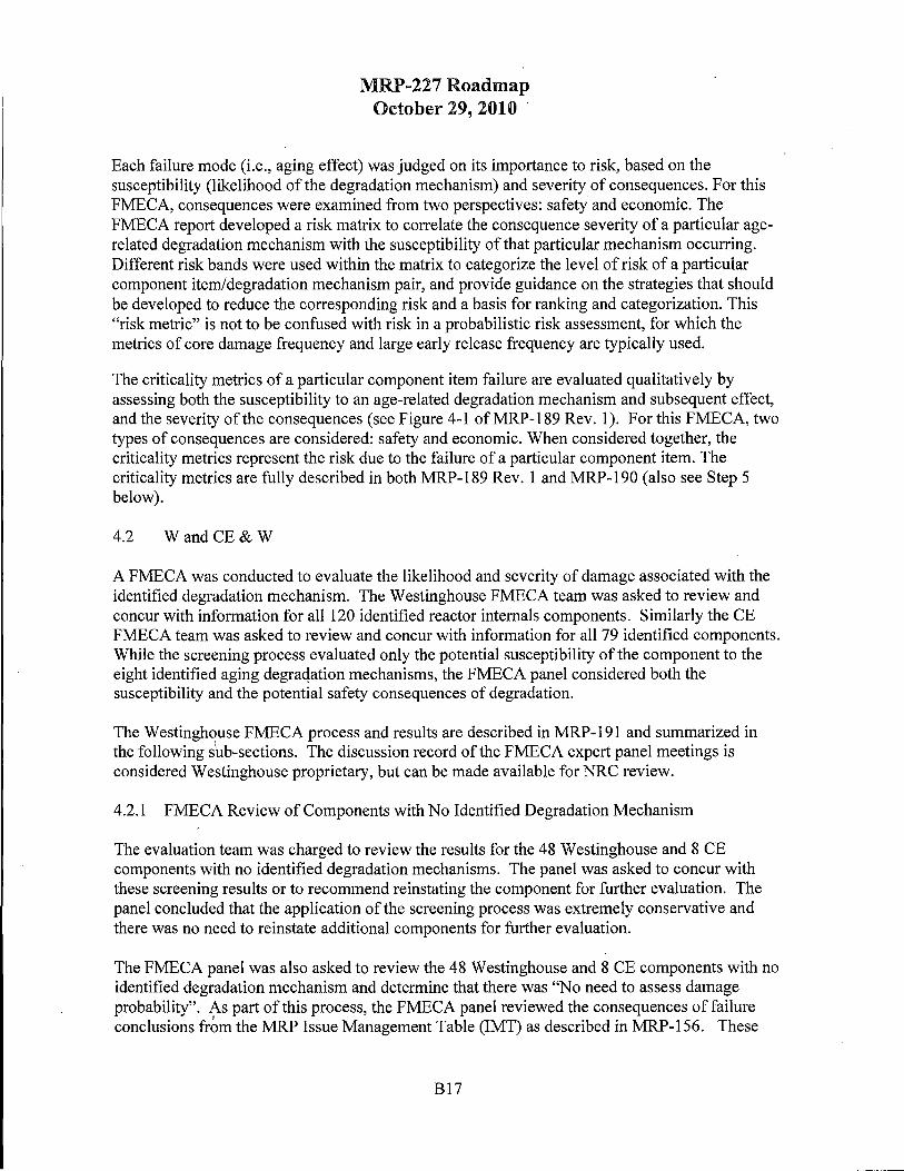
The screening process simply compared the estimated component conditions to the MRP-175 screening levels. Based on this screening process, 48 of the 120 Westinghouse components and 8 of the 79 CE comp-onents were identified with no potential aging considering each of the degradation mechanisms. The components with no screened-in aging degradation mechanisms are identified in MRP-191 Table 6-5 and Table 6-6 for Wand CE components respectively. These components, which are listed in Table 2 and Table 3 of this roadmap document were tentatively placed in Category A, pending review by the FMECA panel in the following step of the assessment process.
B12

MRP-227 Roadmap October 29, 2010
Table 2 Westinghouse Components with No Screened-In Degradation Mechanisms (Data extracted from MRP-191 Table 6-5)
Assembly Sub-Assembly Component Material IMT Conseq. of Failure
Upper Internals Control Rod Guide Tube Anti-rotation 304 ss G Assembly Assemblies and Flow studs and
Down comers nuts ' Bolts 316 ss NONE
Flexureless 304SS G inserts
Housing 304SS G plates
Inserts 304 ss N/A
Lock bars 304SS NONE
Support pin 304SS NONE cover plates
Support pin 316 ss NONE cover plate cap screws
Support pin 304 ss NONE cover plate locking caps and tie straps
Support pin X-750 NONE nuts
Support pin 316 ss NONE nuts
Water flow 304SS N/A slot ligaments
Upper Instrumentation Bolting 316 ss NONE Conduit and Supports
Brackets, 304 ss NONE clamps, terminal blocks, and conduit straps
Conduit seal 304 ss NONE assembly-body, tubesheets
B13

Assembly
Lower Internals Assembly
MRP-227 Roadmap October 29, 2010
Sub-Assembly Component
Conduit seal assembly-tubes
Conduits
Flanqe bases
Locking caps -
Support tubes
Upper Plenum ' I UHi flow
columns
Upper Support Column Adapters Assemblies
Column bodies
Flanges
Lock kevs
Nuts
Upper Support Plate Bolts Assembly
Upper Support Plate Flange Assembly
Lock keys
Ribs
Upper suooort plate
Bottom Mounted BMI column Instrumentation (BMI) lock caps Column Assemblies
Diffuser Plate Diffuser plate
Head Cooling Spray Head cooling Nozzles spray nozzles
Lower Support Column Lower Assemblies support
column nuts
Lower support column sleeves
B14
Material IMT Conseq. of Failure
304SS NONE
304SS NONE
304 ss NONE
304 ss NONE
304SS NONE
304SS G
304 ss G
304SS G
304SS G
304SS G
304SS G
316 ss NONE
304SS N/A
316 ss NONE
304SS G
304SS G
304L SS NONE
304SS NONE
304SS NONE
304 ss G
304SS G

Assembly
Interfacing Components
MRP-227 Roadmap October 29, 2010
Sub-Assembly Component
Lower Support Casting or Lower Forging support
forging
Radial Support Keys Radial support key lock kevs
Secondary Core Support SCS bolts (SCS) Assembly
SCS energy absorber
SCS guide oost
SCS housina
SCS lock kevs
Interfacing Components Clevis insert lock kevs
l_ Clevis insert lock kevs
Head and vessel alignment pin bolts .
Head and vessel alignment pin lock cups
Head and vessel alignment pins
IMT Consequence of Failure - G: Causes significant economic impact A: Precludes a safe shutdown
B15
Material IMT Conseq.
of Failure
304 ss A,G
304SS G
316 ss NONE
304 ss NONE
304SS NONE
304 ss NONE
304 ss NONE
Alloy 600 G
316 ss G
316 ss NONE
304L SS NONE
304 ss NONE

MRP-227 Roadmap October 29, 2010
Table 3 CE Components with No Screened-In Degradation Mechanisms (Data extracted from MRP-191 Table 6-6)
Assembly/ Component Material IMT Conseq. Of Sub-Assembly Failure
Upper Internals Assembly Control rod 316 ss N/A shroud-bolts
GSSS studs 316 ss N/A GSSS spherical UNS N/A washer sets S21800
Flange block A286 SS N/A shear pins
Control Element Assembly Shim bolts 316 ss N/A (CEA)-Shroud Assemblies
Core Support Barrel Core barrel 316 ss N/A Assembly snubber lug bolts
Core barrel A286 SS N/A snubber lug bolts
Alignment key 304 ss NONE dowel pins
4.0 Step 4. Failure Modes, Effects and Criticality Analysis (FMECA)
The fourth step in the process was to perform a Failure Modes, Effects and Criticality Analysis (FMECA). While the specific approach used by AREVA for the B&W units varied with that used by Westinghouse for the CE and W units, the principles employed were similar and produced conservative results. It is important to note that items that were screened as "A" in step 3 above (i.e. - no augmented aging management needed) were re-assessed and this confirmed that the original screening was valid. A summary of each approach is described below. The details of the approaches are described in MRP-190 for the B& W units and MRP-191 for the CE and W units.
4.1 B&W
The objective of the FMECA, described in detail in MRP-190, is to provide a systematic, qualitative review of the B& W-designed PWR internals to identify combinations of internals component items and age-related degradation mechanisms that potentially result in degradation leading to significant risk. The FMECA is used to examine the susceptibility, and safety and economic consequences of identified internals component item/age-related degradation mechanism combinations. For those items screened as "A" (in Step 3 above), the FMECA team provided verification that there were "no credible degradation mechanisms" associated with these items.
The FMECA approach uses inductive reasoning to ensure that the potential failure of each component item is analyzed to determine the results or effects thereof on the system and to classify each potential failure mode according to its severity.
B16
MRP-227 Roadmap October 29, 2010
Each failure mode (i.e., aging effect) was judged on its importance to risk, based on the susceptibility (likelihood of the degradation mechanism) and severity of consequences. For this FMECA, consequences were examined from two perspectives: safety and economic. The FMECA report developed a risk matrix to correlate the consequence severity of a particular agerelated degradation mechanism with the susceptibility of that particular mechanism occurring. Different risk bands were used within the matrix to categorize the level of risk of a particular component item/degradation mechanism pair, and provide guidance on the strategies that should be developed to reduce the corresponding risk and a basis for ranking and categorization. This "risk metric" is not to be confused with risk in a probabilistic risk assessment, for which the metrics of core damage frequency and large early release frequency are typically used.
The criticality metrics of a particular component item failure are evaluated qualitatively by assessing both the susceptibility to an age-related degradation mechanism and subsequent effect, and the severity of the consequences (see Figure 4-1 ofMRP-189 Rev. 1). For this FMECA, two types of consequences are considered: safety and economic. When considered together, the criticality metrics represent the risk due to the failure of a particular component item. The criticality metrics are fully described in both MRP-189 Rev. 1 and MRP-190 (also see Step 5 below).
4.2 W and CE & W
A FMECA was conducted to evaluate the likelihood and severity of damage associated with the identified degradation mechanism. The Westinghouse FMECA team was asked to review and concur with information for all 120 identified reactor internals components. Similarly the CE FMECA team was asked to review and concur with information for all 79 identified components. While the screening process evaluated only the potential susceptibility of the component to the eight identified aging degraqation mechanisms, the FMECA panel considered both the susceptibility and the potential safety consequences of degradation.
The Westinghouse FMECA process and results are described in MRP-191 and summarized in the following s~b-sections. The discussion record of the FMECA expert panel meetings is considered Westinghouse proprietary, but can be made available for NRC review.
4.2.1 FMECA Review of Components with No Identified Degradation Mechanism
The evaluation team was charged to review the results for the 48 Westinghouse and 8 CE components with no identified degradation mechanisms. The panel was asked to concur with these screening results or to recommend reinstating the component for further evaluation. The panel concluded that the application of the screening process was extremely conservative and there was no need to reinstate additional components for further evaluation.
The FMECA panel was also asked to review the 48 Westinghouse and 8 CE components with no identified degradation mechanism and determine that there was "No need to assess damage probability". As part of this process, the FMECA panel reviewed the consequences of failure conclusions frbm the MRP Issue Management Table (IMT) as described in MRP-156. These
B17

MRP-227 Roadmap October 29~ 2010
IMT consequences are noted in Table 2 and Table 3. The IMT treats consideration of the probability of degradation and the consequences of failure as completely independent phenomena.
4.2.2 Westinghouse NSSS
Of the 48 Westinghouse components considered, the only component with potential safetyrelated consequence of failure identified in the IMT was the lower core support forging. (The cast stainless steel version of this component was screened-in due to thermal embrittlement concerns.) Loss of support due to catastrophic failure of this structure could preclude safe shut down of the reactor. THowever, the FMECA panel could not identify any potential cause or mode of catastrophic failure that would require aging management of this large forging. The inspection required for non-age related degradation of this component is specified in ASME Section XI. Therefore the lower support forging was not reinstated for additional evaluation.
There were no potential safety-related concerns ("Precludes safe shutdown" or "Breaches fuel cladding") identified in the IMT for the remaining 4 7 Westinghouse components. Potential economic consequences of failure were noted in 17 of the remaining components. The FMECA panel concurred with this conclusion and concluded that there was no need to include these components in the aging management strategy because there are no safety implications to failure and the economic consequences of unanticipated failure are not severe enough to justify the expenditure of resources to manage such low probabilities of occurrence.
4.2.3 CE
It is difficult to produce a one-to-one correspondence between the CE reactor internals component list in MRP-156 and the list in MRP-227 because additional detail has been added to facilitate the evaluations in MRP-227. However a thorough review showed there are no potential safety related concerns identified for the CE reactor internals components listed in Table 3.
4.2.4 FMECA Review of W and CE Components with One or More Identified Degradation Mechanisms
The FMECA process was employed to assess the likelihood of failure and the likelihood of damage in the remaining 72 Westinghouse and 71 CE components. The FMECA process is described in detail in Section 6 of MRP-191. Additionally it is noted that the members of the FMECA were consistent for all discussions for a given NSSS design.
The FMECA process was conducted on a component-by-component basis and the FMECA categorization was based on the cumulative effects of all eight degradation mechanisms in each component. Potential susceptibility to multiple degradation modes was one of the factors considered by the FMECA panel.
The FMECA panel findings for the Westinghouse reactor internals are provided in Table 6-5 and CE reactor internals in Table 6-6 of MRP-191. The FMECA panel discussions included evaluation of design and analysis data and are therefore considered to be Westinghouse
B18

MRP-227 Roadmap October 29, 2010
proprietary. The FMECA panel findings are also included on the lists of potentially susceptible components in each degradation mechanism series. It should be noted that the FMECA ranking is conservatively based on the cumulative effect of all degradation modes and may not be an indicator of a specific single degradation mode.
5.0 Step 5. Severity Categorization (A, B, C)
The fifth step of the process was to use the results of the FMECA to categorize each of the component items into the categories A, B, and C. As was the case with the FMECA, the severity categorization processes used by AREVA and Westinghouse varied in their specific steps but accomplished the intended goal. All of the reactor internals were placed into one of three categories based on the significance and severity of the potential degradation. A summary of each approach is described below. The details of the approaches and results are described in MRP-189 Rev. 1 and MRP-190 for the B&W units and MRP-191 for the CE and W units.
The FMECA panels for both AREVA and Westinghouse agreed that the "A" (or Category A) events are deemed so improbable (very, very low likelihood of occurrence) that even if a Level B, C, or D event were to occur, the risk impact would not be significant.
5.1 B&W
Categorization of PWR internals was subsequently performed, based on the screening criteria and the likelihood and severity of safety consequences, into categories that range from those components for which these issues are insignificant (Category A) to those components that are potentially moderately significant (Category B) to those components that are potentially significantly affected (Category C). This is detailed in MRP-189 Rev. 1 and MRP-190.
The criticality metrics used in the AREVA FMECA are as follows:
5 .1.1 Susceptibility
The susceptibility metric is a qualitative assessment of the likelihood (expressed as a probability or frequency) that an age-related degradation mechanism might occur, given the existing environmental conditions (e.g., temperature, pressure, fluence, etc.), material properties (type of metal, stress-strain), etc. occurring over the life of a nuclear power unit (up to 60 calendar years, considering license renewal). The susceptibility is unrelated to the consequences, e.g., the component item failure or loss of function. The susceptibility qualitative metric was determined as a result of the expert panel meeting. This criticality metric uses an A, B, C, D scale (increasing frequency).
A - Improbable: not likely to occur (Category A from the initial screening performed in Chapter 3 is synonymous with this susceptibility metric; the Category A results were reviewed by the FMECA expert panel)
B - Unexpected: not very likely to occur, though possible; conditions are such that the age-related degradation mechanism is not expected to occur very often
B19

MRP-227 Roadmap October 29, 2010
C - Infrequent: likely to occur, conditions are such that the age-related degradation mechanism is expected to occur occasionally
D - Anticipated: very likely to occur; conditions are such that the age-related degradation mechanism is expected to occur
B/1 - The susceptibility is sometimes modified with an "I" to indicate an improbable occurrence over the 60-year time period being considered. For example: B/1 indicates an unexpected, b:ut possible, degradation mechanism whose initiation results in a certain state that is not credible (or improbable), e.g., SCC crack leading to a 360 degree weld crack. To carefully distinguish between the different types of likelihood, it is possible (B) to have SCC cracking around a weld, but improbable (I) that such as crack would grow around the weld to the critical crack size needed to fail the weld.
Component item/degradation mechanism pairs identified as improbable are not explicitly evaluated for consequences. However, there are a number of combinations that while identified as improbable will either result in severe consequences, affect the ability to cope with a LOCA, or will require the successful "operation" of the guide lugs. Accordingly, while not classified into a specific risk band, these items, as noted in the footnotes of Table 4-1 (MRP-189 Rev. 1) should never be removed from the current ASME inspection requirements (VT-3).
5 .1.2 Severity of Consequences
Severity classifications are assigned to provide a qualitative measure of the potential consequence resulting from a component item failure. For those component item/age-related degradation mechanism pairs for which the susceptibility metric was assigned an "A," i.e., "Category A," there was no subsequent evaluation of the consequence due to the very low (i.e., improbable) event frequency. For the PWR internals FMECA, two aspects of consequences are considered: safety and economic. Thus, there are two columns in the FMECA for whiph qualitative metrics are assigned. The two sets of severity of consequence qualitative metrics were determined as a result of the expert panel meeting. These criticality metrics use a I, 2, 3, 4 scale (increasing severity).
For severity of consequences (safety), the qualitative metric has been defined as:
I. Safe: no or minor hazard condition exists 2. Marginal: safe shutdown is possible (though with reduced margins to adequately cool
the core and/or successfully insert the control rods); localized fuel assembly damage 3. Severe: safe shutdown is possible (though with very reduced margins to adequately
cool the core and/or successfully insert the control rods); core damage (multiple damaged fuel assemblies)
4. Critical: safe shutdown is not possible (margins to adequately cool the core and/or successfully insert control rods are totally eroded); extensive core damage
B20

MRP-227 Roadmap October 29, 2010
The safety consequence metric assigned will be the highest value, i.e., bounding consequence, for normal operation or design basis event (transient, LOCA, seismic) when the failure mode is not detectable. Typically, the safety consequences were estimated to be the same for normal operation and a design basis event (when the failure mode is not detectable). Note that there were no severity of consequences (safety) identified with a metric of 4.
For severity of consequences (economic), the qualitative metric has been defined as:
1. No or trivial cost 2. Cost that can be generally handled within the existing unit budget and resources
( order of millions of dollars) 3. Cost that exceeds the normal unit budget and resources (order of tens of million
dollars) 4. Cost that potenti~lly affects the utility's overall financial health (order of hundreds of
million dollars)
Note that the economic consequences assume that the failure mode is discovered through some means, e.g., unit inspection, notification of discovery at another unit site, etc. This is also conservative when assessing the risk. Note that the severity of consequences (economic) metric was not used in assignment of the preliminary Category A, B, and C items.
Based upon the FMECA results, the PWR internals that were potentially the most affected were placed into Category C, while the components that are potentially only moderately affected were placed into Category B. In addition, the FMECA process determined that some components not initially Category A were sufficiently unaffected by consequences to be subsequently placed into Category A.
The risk matrix in MRP-189 Rev. 1 (Figure 4-1) does not include a column for the susceptibility metric value of"A" because, as noted in MRP-190 (Section 3.2), the "A" (or Category A) events are deemed so improbable (very, very low likelihood of occurrence) that the safety severity of consequence metric was not evaluated, implying that even if there was an adverse consequence, the risk impact would be insignificant. However, to clarify how component items were categorized, the Figure 1 below provides a correlation to the risk matrix (Figure 4-1 of MRP-189 Rev. 1) and also includes a column for Category A items:
B21

A
'SI"
.8 1 A
s 0
ct:: "' Q) u c:: Q) ::; O" Q)
"' 2 c:: A 0 u .0 ~ c,l
er, bD .s ~ 3 A Q) .... u ..s
* 4 A
MRP-227 Roadmap October 29, 2010
Increasing Susceptibility from A to D
B C
A B
' B C
C C
C C
D
B
C
C
C
Figure 1: Consequence vs. Susceptibility for Ranking *Note: There are no component items in the B& W-design internal with an assigned safety consequence metric equal to 4; therefore, the last row of this figure is not applicable to the MRP effort.
B22

MRP-227 Roadmap October 29, 2010
r
The initial Category A, B, and C results for selected B& W components are provided in Table 4.
Table 4 Initial Category A, Band C Results for Selected B&W Components (Extracted from Tables 4-1 and 4-2, MRP-189 Rev. 1)
Component Safety Economic A, B, C (MRP189) Band Band Rev.1
CRGT Spacer Castings I Ill B
CRGT Control Rod Guide Tubes II Ill B
CRGT Control Rod Guide Sectors II Ill B
CSS Vent Valve Top and Bottom Retaining I Ill B Rings
CSS Vent Valve Disc I Ill B
CSS Vent Valve Disc Shaft or Hinge Pin I Ill B
I II Core Barrel Cylinder B
I Ill
Ill Ill
Baffle Plates II Ill C
, II II
Ill Ill
Former Plates II Ill C
Ill Ill
II II Core Barrel-to-Former Plate Dowels B
I I
I I
Lower Grid Support Post Cap Screw I I B
I I
II Ill Flow Distributor (FD) Bolts C
IV V
B23

MRP-227 Roadmap October 29, 2010
L
Component Degradation Safety Mechanism Band
CRGT Spacer Castings TE I
CRGT Control Rod Guide Tubes Wear II
CRGT Control Rod Guide Sectors Wear II
CSS Vent Valve Top and Bottom Retaining TE I Rings
CSS Vent Valve Disc TE I
CSS Vent Valve Disc Shaft or Hinge Pin TE I
sec I Core Barrel Cylinder
IE I
IASCC Ill
Baffle Plates IE II
vs II
IASCC Ill
Former Plates IE II
vs Ill
IE II Core Barrel-to-Former Plate Dowels
vs I
Fatigue I
Lower Grid Support Post Cap Screw IE I
Wear I
Flow Distributor (FD) Bolts sec IV
Economic A,B,C Band (MRP189 Rev. 1)
Ill B
Ill B
Ill B
Ill B
Ill B
Ill B
II B
Ill
Ill
Ill C
II
Ill
Ill C
Ill
II B
I
I
I B
I
V C
It is also interesting to compare the IMT (MRP-157) results to the FMECA results. For each component item that constitutes part of the PWR internals, consequences of failure evaluations were performed in the IMT considering each of the applicable degradation mechanisms (without regard for existing mitigation strategies). This includes following the logical path from component failure to safe shutdown. The consequences evaluation is considered to be realitybased not design-based, so these evaluations are not related to the design bases of the B& W units. Scenarios that rely on a sequence of low probability events reach to get a failure may be documented as such and the failure evaluation terminated. Systems that must operate correctly to satisfy the defined failure sequence are identified. It is also noted that the evaluations do not consider electrical system failures due to component item degradation ( e.g., RCS instrumentation). The expert panel participants are listed in the IMT and represent a broad scope
B24

MRP-227 Roadmap October 29, 2010
of expertise in the design and operation of the B& W units. In the IMT, the general approach used in the consequences of failure evaluations was as follows:
• For each component item, consequences of failure evaluations were performed considering all of the applicable degradation mechanisms identified by the MDM. The evaluations assume that the unit is initially. at full power steady-state conditions. Assuming failure while the unit is at other Level A service conditions impacts the availability of various systems, the unit conditions, and therefore the sequence of events to safe shutdown.
• Level A conditions other than full power, as well as Level B, C, and D conditions are considered coincident with component degradation that does not require unit shutdown during normal operations. These coincident conditions are not rigorously treated, but are discussed from the perspective of their potential contribution to adverse consequences.
[For clarification, this means that service level events (Levels B, C, and D) were not superimposed along with gross failure from aging degradation of the component or item under consideration. This is a similar approach to that used in Chapter 15 of the FSAR.]
• The evaluations consider the functions that the component item supports and the impact that the degradation might have on the ability of the reactor vessel internals to continue performing thoseat functions. For instance, through-wall cracking, significant wear (at a location of contact or close tolerance), or embrittlement, could compromise the structural integrity of a component item, so each is considered in the evaluations. If different degradation mechanisms lead to different results, then each is treated individually. Multiple degradation sites are not considered ·because common mode and/or cascading failures are not in the scope of the project. Loose parts were generically evaluated as well.
The following consequences of failure were evaluated:
A. Precludes the ability to reach safe shutdown B. Causes a design basis accident C. Causes significant onsite and/or offsite exposure D. Jeopardizes personnel safety E. Breaches reactor coolant pressure boundary F. Breaches fuel cladding G. Causes a significant economic impact
As shown in Table 4-14 of the IMT (MRP-157), none of the safety-related consequences of failure (items A-E) were determined to be applicable (similar to the FMECA results) and only consequences of failure items F and G were determined to be applicable to the B& W PWR internals. However, it should be noted that there were differences between the consequence evaluations performed in the IMT and the FMECA. An explanation of the differences is provided in Appendix B of MRP-190.
B25

5.2 CE& W
MRP-227 Roadmap October 29, 2010
All of the reactor internals were placed into one of three categories based on the significance and severity of the potential degradation. These three categories were:
Category A: Component items for which aging degradation significance is minimal orand aging effects are below the screening criteria.
Category B: Component items above screening levels but are not "lead" component items and aging degradation significance is moderate.
Category C: "Lead" component items for which aging degradation significance is high or moderate and aging effects are above screening levels.
5.2.1 Components Placed in Category A Based on FMECA
After review and confirmation by the FMECA panel, all of the components that were not identified in the screening process for potential susceptibility to any of the eight degradation mechanisms were retained as originally placed in Category A.
The FMECA panel also observed that, due to the conservative nature of the screening process, many components that had been identified for potential degradation were known to not be susceptible to degradation. The most obvious example of the conservative nature of the process was that the surveillance capsule components were identified for irradiation embrittlement because the screening process attributed the peak core barrel fluence to all of the potential attachments. However the FMECA panel observed that the surveillance capsules contain dosimetry packages and the fluences were known to be well below the threshold for irradiation embrittlement.
To more accurately reflect the degradation potential for the components and account for the overly conservative nature of the screening process, the FMECA panel recommended that components with low failure likelihood and either low or medium damage likelihood, especially where the potential for any damage was considered to be readily detectable and manageable in attaining a safe operational state, be moved to Category A. Components with low failure likelihood and high damage likelihood were not considered as candidates to be moved to Category A under any conditions. These criteria are illustrated in Figure 2. By definition, all components with potential safety concerns were classified as high damage likelihood. Therefore, no components with identified safety concerns were affected by this re-classification.
B26

MRP-227 Roadmap October 29, 2010
Failure Consequence (Damage Likelihood) Likelihood
Low Medium High
High 2 3 3
Medium - 1 2 3
-
Low I 1 1 I 2 CatE !QOry A • - - -
None I 0 0 0 I
Figure 2 FMECA Criteria for Aging Significance Table
The 41 Westinghouse components with one or more identified degradation mechanisms that were moved to Category A based on the FMECA results are listed in Table 5. The 48 CE components moved to Category A based on the FMECA are listed in Table 6. The FMECA panel identified 27 Westinghouse and 27 CE components with low failure probability and lo~ damage consequence. There were an additional 14 Westinghouse and 21 CE components with low failure probability and medium damage consequence. Although the FMECA panel identified a potential economic consequence of failure in the components with medium likelihood of damage, the low failure probability resulted in minimal risk to plant operation. Therefore these 14 Westinghouse and 21 CE components were also placed in Category A. Application of the FMECA process to the Lower Core Plate Fuel Aligmnent Pin Bolts is provided in Example 1.
B27

MRP-227 Roadmap October 29, 2010
Example 1: Lower Core Plate Fuel Alignment Pin Bolts Placed In I
Category A Based on FMECA
Original screening results: MRP-191 Table 5-1 • IASCC, Wear, Fatigue, Irradiation Embrittlement, Void Swelling, Irradiation
Induced Stress Relaxation/Creep , Functional Description: MRP-191 Section C.2.1
• The LCP is bolted at the periphery to a ring welded to the ID of the core barrel. The span of the plate is supported by lower support columns that are attached at their lower end to the lower support plate. At the center, a removable plate is provided for access to the vessel lower head region.
FMECA Conclusion: MRP-191 Table 6-5 • Low Failure Probability, Low Consequence
- Screening process overestimated fluence because it assumed components attached to LCP saw same peak fluence. These bolts are located on periphery. No history of failures Bolts are redundant fasteners.
B28
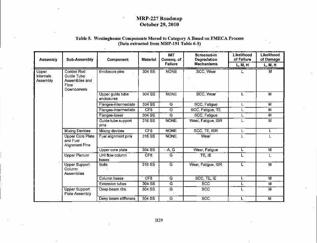
Assembly
Upper Internals Assembly
MRP-227 Roadmap October 29, 2010
Table 5. Westinghouse Components Moved to Category A Based on FMECA Process (Data extracted from MRP-191 Table 6-5)
IMT Screened-in Likelihood Sub-Assem_bly Component Material Conseq. of Degradation of Failure
Failure Mechanisms L,M,H
Control Rod Enclosure pins 304 ss NONE sec, Wear L Guide Tube Assemblies and Flow Downcomers
Upper guide tube 304SS NONE SCC, Wear L enclosures
Flanges-intermediate 304SS G sec, Fatigue L
Flanges-intermediate CF8 G sec, Fatigue, TE L
Flanges-lower 304SS G sec, Fatigue L
Guide tube support 316 ss NONE Wear, Fatigue, ISR L pins
Mixing Devices Mixing devices CF8 NONE sec, TE, ISR L
Upper Core Plate Fuel alignment pins 316 ss NONE Wear L and Fuel Alignment Pins
Upper core plate 304SS --A,G Wear, Fatigue L
Upper Plenum UHi flow column CF8 G -. TE, IE L bases
Upper Support Bolts 316 ss G Wear, Fatigue, ISR L Column Assemblies
Column bases - CF8 G sec, TE, IE L
Extension tubes 304SS G sec L
Upper Support Deep beam ribs 304 ss G sec L Plate Assembly
Deep beam stiffeners 304SS G sec L
B29
Likelihood of Damage
L,M,H
M
M
M
M M
M
L
L
M
L
M
M
M
M
M

Assembly Sub-Assembly Component
Inverted top hat (1TH) flange
Inverted top hat (1TH) upper support plate
Lower Baffle and Baffle bolting lock Internals Former Assembly bars Assembly
Bottom Mounted BMI column bolts Instrumentation (BMI) Column Assemblies
BMI column extension bars
BMI column nuts
Irradiation Irradiation sp!cimen Specimen Guides guides
Irradiation specimen guide bolts
Irradiation specimen guide lock caps
Specimen plugs
Lower Core Plate Fuel alignment pins and Fuel Alignment Pins
LCP-fuel alignment pin bolts
LCP-fuel alignment pin lock caps
MRP-227 Roadmap October 29, 2010
IMT Material Conseq. of
Failure
304 ss N/A
304SS N/A
304SS NONE
316 ss NONE
304 ss G
304SS NONE
304SS NONE
316 ss NONE
304L SS NONE
304SS NONE
316 ss NONE
316 ss NONE
304L SS NONE
B30
Screened-in Likelihood Likelihood Degradation of Failure of Damage Mechanisms L,M,H L,M,H
SCC, Fatigue L M
sec L M
IASCC, IE, VS L L
Fatigue L L
IASCC, IE, VS L L
IASCC,Wear, Fatigue, L L IE, VS, ISR
Wear, IE L L )
IASCC, Wear, Fatigue, L L IE, ISR
IE L L
IE L L
IASCC, Wear.IE, VS L L
IASCC, Wear, Fatigue, L L IE, VS, ISR
IASCC, IE, VS L L

Assembly · Sub-Assembly Component
Neutron Neutron panel bolts Panels/Thermal Shield
Neutron panel lock caps
Thermal shield bolts
Thermal shield dowels Thermal shield or neutron panels
Radial Support Radial support key Keys bolts
Radial Support Radial support keys Keys Secondary Core SGS base plate Support (SGS) Assembly
Interfacing Interfacing Clevis inserts Components Components
Clevis inserts
Clevis inserts
Internals hold-down spring
Internals hold-down spring
MRP-227 Roadmap October 29, 2010
IMT Material Conseq. of
Failure
316 ss NONE
304SS NONE
316 ss NONE
316 ss NONE
304SS G
304SS G
304SS G
304SS NONE
Alloy 600 G
304 ss G
Stellite G
304SS G
403 ss G
IMT Consequence of Failure - G: Causes significant economic impact A: Precludes a safe shutdown
B31
Screened-in Likelihood Likelihood Degradation of Failure of Damage Mechanisms L,M,H L,M,H
IASCC, Wear, Fatigue, L L IE, ISR
IE L L
IASCC, Wear, Fatigue, L L IE, ISR
-- IE L L
IE L L
Wear L L
SCC, Wear L L
sec L L
Wear L L
Wear L L Wear L L Wear L L
Wear, TE L L

Assembly/ Sub-Assembly
Upper Internals Assembly
MRP-227 Roadmap October 29, 2010
Table 6. CE Components Moved to Category A Based on FMECA Process (Data extracted from MRP-191 Table 6-6)
Likelihood Component Material IMTConseq. Screened-in Degradation of Failure
of Failure Mechanisms L,M,H
Upper guide 304SS G sec L structure support plate
Upper guide 304 ss G sec, Wear L structure support flanQe-uooer Upper guide 304 ss G sec L structure support flange-lower Cylindrical skirt 304SS G sec L Grid plate 304 ss G sec L Control rod 304SS N/A sec L shroud-grid ring
Control rod 304 ss N/A sec L shroud-grid beams Control rod 304 ss N/A sec L shroud-cross braces GSSS guide 304SS N/A sec L structure plate
GSSS support 304 ss N/A sec L cylinder
Flange blocks 304 ss N/A Wear L
B32
Likelihood of Damage
L,M,H
M
M
M
M M M
M
M
M
M
L

Assembly/ Component Material Sub-Assembly
Flange block 410 ss bolts RVLMS support 304SS structure tubes
Fuel bundle 316 ss guide pins
Fuel bundle 304SS guide pin nuts
- Hold down ring 403 SS/ F6NM
Belleville Alloy 718 washer
Lower Support Core support 316 ss Structure plate bolts
Core support 304SS plate dowel pins
Anchor block 316 ss bolts Anchor block 304 ss dowel pins
Fuel alignment 304SS pins Core support 304 ss
- beams Bottom plate 304SS
!Cl support 304 ss columns
MRP-227 Roadmap October 29, 2010
IMTConseq. Screened-in Degradation of Failure Mechanisms
N/A TE
N/A sec, Wear, Fatigue
N/A Wear, Fatigue, ISR
N/A Wear, Fatigue, ISR
G .. Wear, TE
N/A Wear
N/A IASCC, Wear, Fatigue, IE, ISR
N/A IE
N/A Wear, Fatigue, IE, ISR
N/A IE
NONE IE
A,G SCC, Wear
N/A sec
N/A sec
B33
Likelihood Likelihood of Failure of Damage
L,M,H L,M,H
L L
L L
L L
L L
L L
L L
L L
L L
L L
L L
L M
L L
L L
L L

Assembly/ Component Material
Sub-Assembly
Control Element CEA shrouds 304 ss Assembly (CEA)-Shroud Assemblies -
CEA shrouds CPF8/CF8 CEA shroud 304 ss bases CEA shroud CFS bases CEA shroud 304 ss
. extension shaft guides
Modified CEA CFS shroud extension shaft guides Internal/external 304 ss spanner nuts
CEA shroud A286 SS bolts CEA shroud tie 304SS rods Snubber blocks 304 ss Snubber shims XM-29
-core Support Core barrel 304,321 Barrel snubber lugs or 348 SS Assembly
Alignment keys A286 SS Alignment keys 304 ss Core barrel 304 ss outlet nozzles
MRP-227 Roadmap October 29, 2010
IMT Conseq. Screened-in Degradation of Failure Mechanisms
G sec -
G sec, TE G sec
G sec, TE
G sec
G sec, TE
NONE sec
NONE Wear, Fatigue, ISR
N/A sec
N/A sec N/A Wear G SCC, Wear
NONE Wear NONE Wear
G sec, Wear
B34
Likelihood Likelihood of Failure of Damage
L,M,H L,M,H
L M
L M L M
L M
L M
L M
L M
L M
L M
L L L L L L
L L L L L M

Assembly/ Component Material Sub-Assembly
Thermal shield 304 ss Thermal shield 304 ss support pins
Core Shroud Guide Jugs 304 or Assembly 348 ss
Guide lug 304,321 inserts or 348 SS
In-Core JCJ guide tubes 316 ss Instrumentation (ICI)
JCJ nozzle 304 ss support plate
JCJ thimble 304SS support plate
JCJ thimble 304SS tubes-upper
MRP-227 Roadmap October 29, 2010
IMT Conseq. Screened-in Degradation of Failure Mechanisms
G sec NONE Wear
NONE sec
NONE Wear
NONE sec, JE
G sec
G sec, Wear
NONE SCC, Wear
B35
Likelihood Likelihood of Failure of Damage
L,M,H L,M,H
L L L L
L L
L L
L L
L L
L L
L L

MRP-227 Roadmap October 29, 2010
5.2.2 Components Placed in Categories Band C
The remaining 31 Westinghouse and 23 CE "non-Category A" components were evaluated and placed in Category B or Category C based on the FMECA results and analysis using the Category definitions. Each component was assigned a FMECA aging significance grouping based on the FMECA categories as indicated in Figure 2.
Two exceptions were noted to the components identified by the screening and FMECA process. First, it was observed that the X-750 flexures in Westinghouse plants were obsolete due to plant modifications to resolve the aging concerns. These flexures were removed from subsequent consideration. Second, it was noted that the Zr-4 thimble tubes in the CE In-Core Instrumentation system were known to be subject to an irradiation growth phenomenon that was not addressed as one of the eight degradation modes. These thimble tubes were automatically placed in Category C.
Of the remaining components, 12 Westinghouse and 13 CE components ranked as medium failure likelihood and low failure consequence were automatically placed in Category B. Evaluations of the impact of each of the identified degradation mechanisms were used to rank the significance of the remaining 19 Westinghouse and 9 CE components. Based on that ranking, 12 Westinghouse components were identified as Category C and an additional 6 Westinghouse components were added to the Category B list. A total of 6 CE components (including the Zr-4 thimble tubes mentioned above) were identified as Category C, with the remaining 4 components added to Category B.
There were two additional exceptions to this categorization process discussed in Section 7 .2 of MRP-191:
I. The Westinghouse lower support casting, had been identified as a FMECA Group 2 component based on the consequences of an assumed failure. However, consistent with the MRP-134 definitions, this component was placed into Category A after consideration of the very low probability of degradation and consequence due to the identified thermal embrittlement degradation mechanism.
2. The otherOne exception is the internals hold down spring fabricated from 304 SS. Thermal "ratcheting", leading to permanent deformation, is not one of the explicitly characterized degradation mechanisms.from MRP-175 but may occur in this component and reduce the spring hold-down force over time. This particular phenomenon was assessed to have a moderate likelihood of occurrence; hence, it was assigned to Category B to warrant attention during the development of Inspection and Evaluation (J&E) guidelines.
B36

MRP-227 Roadmap · October 29, 2010
The final list of 31 Westinghouse and 23 CE Category B and Category C items is provided in MRP-191 Tables 7-2 and 7-3. This information is summarized here in Tables 6 and 7. This list of Category Band C Components is carried forward into MRP-227 Tables 3-2 and 3-3. The aging management strategy for the reactor internals is built around examination of these items.
B37

I
MRP-227 Roadmap October 29, 2010
Table 76 Summary of Westinghouse Category Band Category C Components
Assembly Sub-Assembly Component Material Degradation Mechanism
Upper Internals Control Rod Guide C tubes 304 ss Wear Assembly Tube Assemblies and
Flow Downcomers Flanges-lower : CFS sec,
Fatigue,TE, IE
Flexures X-750 sec, Fatigue,TE,
IE Guide 304 ss SCC, Wear, olates/cards Fatiaue Guide tube X-750 sec, Wear, support pins Fatique, ISR Sheaths 304 ss Wear
Upper Support Plate Upper support 304 ss sec, ' Assembly ring or skirt Fatigue.TE,
IE Lower Internals Baffle and Former Baffle-edge 316 IASCC, Assembly Assembly bolts SS/347 Wear,
ss Fatigue, IE, VS, ISR
Baffle plates 304 ss IASCC, IE,. vs
Baffle-former 316 IASCC, bolts SS/347 Wear,
ss Fatigue, IE, VS, ISR
B38
IMT Likelihood Likelihood MRP-191 Conseq. of Failure of Damage Category
of Failure L,M,H L,M,H A, Bore
G M M C
G M M B
G H M
G H M C
NONE H M C ,
G M M C
G M M B
NONE H M C
G M L B
G H L C
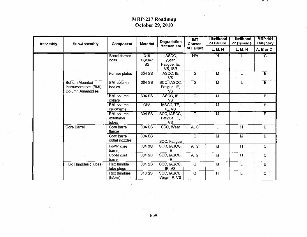
Assembly Sub-Assembly
Bottom Mounted Instrumentation (BMI) Column Assemblies
Core Barrel
Flux Thimbles (Tubes)
MRP-227 Roadmap October 29, 2010
Component Material Degradation Mechanism
Barrel-former 316 IASCC, bolts SS/347 Wear,
ss Fatigue, IE, VS, ISR
Former plates 304 ss IASCC, IE, vs
BMI column 304 ss sec, IASCC, bodies Fatigue, IE,
vs BMI column 304 ss IASCC, IE, collars vs BMI column · CF8 IASCC, TE, cruciforms IE, VS BMl-column 304 ss sec, IASCC, extension Fatigue, IE, tubes vs Core barrel -304 ss SCC, Wear flanQe Core barrel 304SS outlet nozzles sec, Fatigue Lower core 304SS sec, IASCC, barrel IE Upper core 304SS sec, IASCC, barrel IE Flux thimble 304 ss sec, IASCC, tube PIUQS IE. VS Flux thimbles 316 ss sec, IASCC, (tubes) Wear, IE. VS
B39
IMT Likelihood Likelihood MRP-191 Conseq. of Failure of Damage Category
of Failure L,M,H L,M,H A, B orC
N/A H L C
G M L B
G M L B
G M L B
G M L B
G M L B
A,G L H B
G M M B
A,G M H C
A,G M H C
G M L B
G H L C

Assembly Sub-Assembly
Lower Core Plate and Fuel Alignment Pins
Lower Support Column Assemblies -
Lower Support Casting or Forging Neutron Panels/Thermal Shield
Interfacing Interfacing Components Components
MRP-227 Roadmap October 29, 2010
Component Material Degradation Mechanism
Lower core 304SS sec, IASCC, plate Wear,
Fatigue, IE. vs
XL lower core 304SS sec, IASCC, plate Wear,
Fatique, IE Lower support CF8 IASCC, TE, column bodies IE, VS Lower support 304SS IASCC, IE, column bodies vs Lower support 304SS IASCC, column bolts Wear,
Fatigue, IE, VS, ISR
Lower support CF8 TE castina Thermal shield 304SS IASCC, flexures Wear,
Fatigue, IE, ISR
Clevis insert X-750 SCC, Wear bolts Internals hold- 304SS SCC, Wear down spring
Upper core 304SS Wear plate alignment oins
B40
IMT Likelihood Likelihood MRP-191 Conseq. of Failure of Damage Categorv of Failure L,M,H L,M,H A, B orC
A,F,G M M C
NIA M M C
G M L B
G M L B
G M L B
A,G L H A
NIA M L B
G M L B
G L L B
NONE M L B

MRP-227 Roadmap October 29, 2010
Table 87 Summary of CE Category B and Category C Components
Assembly/ Degradation Sub-Assembly Component Material
Mechanism
Upper Internals Fuel alignment plate 304SS sec, Wear, Assembly Fatigue Lower Support Core support plate 304/304L SS sec, IASCC, Structure Wear, Fatigue, IE
Fuel alignment pins A286 SS IASCC, Wear, Fatique, IE, ISR
Core support 304 ss sec, IASCC, columns Fatique, IE Core support CF8 sec, IASCC, columns Fatigue, TE, IE Core support deep 304SS sec, IASCC, beams Fatigue, IE
Core support column 316 ss IASCC, Wear, bolts Fatigue, IE, ISR
Control Element Instrument tubes 304SS sec, Fatigue Assembly (CEA)-Shroud Assemblies
Core Support Barrel Upper cylinder 304 ss sec Assembly
Lower cylinder 304 ss sec, IASCC, IE Upper core barrel 304 ss SCC, Wear flange
Lower core barrel 304 ss SCC, Fatigue flange
Thermal shield UNS S21800 Wear, Fatigue, positioning pins ISR
B41
IMT Likelihood Likelihood MRP-191 Conseq. of of Failure of Damage Category
Failure L,M, H L,M,H A, Bore
A,G M M 8
A,G M M C
NONE M M C
A,G M L 8
A,G M L 8
A,G M M C
NONE M L 8
NONE M L 8
A,G L H 8
A,G M H C A,G L H 8
A,G L H 8
NONE M L 8

Assembly/ Sub-Assembly
Component
Core Shroud Shroud plates Assembly
Former plates
Ribs
Rings
Core shroud bolts
Barrel-core shroud bolts
Core shroud tie rods
Core shroud tie rod nuts
Guide lug insert bolts -- -
In-Core ICI thimble tubes-Instrumentation (ICI) lower
MRP-227 Roadmap October 29, 2010
Degradation Material
Mechanism
304 ss sec, IASCC, IE, vs
304SS sec, IASCC, IE, vs
304SS sec, IASCC, IE, vs
304SS sec, IASCC, IE, vs
316 ss IASCC, Wear, Fatigue, IE, VS,
ISR 316 ss IASCC, Wear,
Fatigue, IE, ISR
348 ss Wear, Fatigue, IE, ISR
316 ss Wear, Fatigue, IE, ISR
A286 SS Wear, Fatigue, ISR
Zircaloy-4 Wear
B42
IMT Likelihood Likelihood MRP-191 Conseq. of of Failure of Damage Category
Failure L,M,H_ L,M,H A, Bore
G M M C
G M L B
G M L B
G M L B
G M L B
G M L B
N/A M L B
N/A M L B
N/A M L B ' -
NONE M L C

MRP-227 Roadmap October 29, 2010
6.0 Step 6. Engineering Evaluation and Assessment
The sixth step of the process was to perform an assessment of the PWR internals components and items that would most be affected by the aging degradation mechanisms (preliminary Category Band C items from the previous steps). Step 6 has previously been identified as a "Functionality Evaluation" or "Functionality Assessment" in each of the reference documents,. It was determined that these terms may have been somewhat misleading. It has been renamed herein as Engineering Evaluation and Assessment to more closely describe the work that has actually been performed Step 6 has been identified as a "Functionality Evaluation" or "Functionality Assessment" in each of the reference documents, for which the chosen words unfortunately are now felt to have been somewhat misleading. It has been renamed herein for clarification of the work that has actually been performed. [Or, some wording similar to this!]
As was the case with the FMECA and the severity categorization, the engineering evaluation processes used by AREY A and Westinghouse varied in their specific steps but accomplished the intended goal. A summary of each approach is described below. Finite element analyses of the core barrel regions for the three designs were performed as described in MRP-229 for the B&W units and MRP-230 for the CE and W units. The details of the approaches and results are described in MRP-229 231 for the B& W units and MRP-230 232 for the CE and W units. The results were carried into the aging management strategies documented in MRP-231 for B& W units and MRP-232 for CE and W units.
6.1 B&W
The engineering evaluation and assessment (aka, functionality assessment) work performed included structural evaluation with finite element analysis (PEA), engineering analysis, operating experience, and review of inservice inspection results. (Note: the functionalityengineering evaluation and analysis assessment effort is not a requalification of the design basis considering the potential age-related degradation).
6.1.1 PEA Analyses
Two finite element analyses (PEA) (also call "functionality analyses" in Sections 2.1 and 2.2 of MRP-231) were performed for the B& W units within the MRP effort:
• A genericn analysis of the core barrel assembly, which includes the core barrel cylinder, baffle plates, former plates, baffle-to-former (FB) bolts, baffle-to-baffle (BB) bolts, and core barrel-to-former (CB) bolts. The thermal shield and bolt locking devices are not modeled and analyzed in this evaluation.
e A genericn analysis of the currently installed upper core barrel (UCB) bolts, lower core barrel (LCB) bolts, and flow distributor (FD) bolts on a generic basis.
B43

6.1.1.1 Core Barrel Assembly
MRP-227 Roadmap October 29, 2010
FEA is performed for the core barrel assembly due to the large number of Category "C" and "B" items in the assembly and potential interactions between the aging degradation mechanisms. The modeling was based on a representative B& W PWR internals unit design, using irradiated and aged material properties, and was performed to model several irradiation-induced aging degradation mechanisms and their interactions (see details in MRP-229).·
Included in this analysis was the evaluation of selected austenitic stainless steel components that were judged to be susceptible to irradiation-induced degradation of mechanical and/or physical properties using an ANSYS-based subroutine developed by ANA TECH Corporation for EPRI. The stainless steel material models employed in the calculations account for the effects of plasticity, irradiation-enhanced creep, stress relaxation, irradiation-assisted stress corrosion cracking, void swelling, and irradiation embrittlement as a function of temperature and dose. The project team focused on finding the integrated effects of material aging combined with steady-state operational characteristics of the reactor internals.
These analyses subjected representative internals components/assemblies to core heating and dose for 40 fuel cycles or 60 years. Conservative core loading, heat transfer, and mechanical preloads were applied. The aging degradation modeling provided insight for the locations and progression of aging degradation. However, it is not considered capable of predicting the precise timing or location of various aging degradation effects. Therefore, the MRP-227 inspection schedule for the core barrel assembly is primarily based on the industry operating experience and inspection results to date. The core barrel assembly FEA aging modeling results provided additional assurance that the inspection schedule will detect the aging degradation and their interactions before functionality is affected.
The FEA modeling of aging degradation for the core barrel assembly was based on representative configurations and operational histories, which were generally conservative, but not necessarily bounding in every parameter. These assumptions were a conservative representation of,U.S. PWR operating units, all of which implemented low-leakage core-loading patterns early in operating life.
Certain items were found to exhibit possible susceptibility to age-related degradation due to prolonged radiation, stress, and temperature (for example, baffle-to-former bolts). Other items are not likely to exhibit susceptibility to age-related degradation that could affect functionality from long-term reactor operation. Results are summarized in Section 4 of the MRP-229 report.
None of the Core Barrel Assembly components were downgraded to "No Additional Measures" as a result of the FEA analysis. In addition, some aging degradation effects such as baffle-toformer bolt overload were identified based on the FEA analysis.
However, some of the Core Barrel Assembly components were downgraded from "C" to "B". For example, the baffle plates were downgraded from "C" to "B", which were eventually placed in the "Primary" group. In addition, some components had an individual aging degradation mechanism downgraded from "C" to "B" or to "A", but could not be downgraded to "No Additional Measures" due to the remaining aging degradation mechanisms. For example, void
B44

MRP-227 Roadmap October 29, 2010
swelling was downgraded from "C" to "A" for baffle-to-former bolts, which remained as a "C" item and eventually was placed in the "Primary" group.
6.1.1.2 High-Strength Bolt Rings
The UCB and LCB bolt locations have a core support function and are categorized as "C". Detailed FEA is performed in accordance with the current ASME Section 3 design criteria under normal operating and upset con~itions.
Variations in bolt replacement patterns or non-functional bolts were not considered in the analysis. The loads considered were:
• Preload e Thermal stresses for the case of High-Leakage End-Of-Cycle (HL-EOC) • Mechanical load including hydraulic forces and flow-induced vibration (FIV) • Deadweight loads
None of these bolts/components were downgraded to "No Additional Measures" as a result of the FEA analysis. The UCB and LCB bolts remained as Category C and were eventually placed in the Primary group. The FD bolts were downgraded from Category C to Category B and were eventually placed in the Expansion group.
The results are used in the final two steps of the MRP work for assessing the previous B& WOG Materials Committee conclusions and recommendations regarding these bolts. Due to the considerable differences among the units, additional analysis on a unit-specific basis is underway withinwas performed by the PWROG.
6.1.2 Other Evaluations
Evaluations for the remaining preliminary Category B and C items (i.e., engineering assessment, operating experience, and review of inservice inspection results) were performed as necessary and are documented in Section 2 ofMRP-231.
The results from the engineering evaluation and assessment efforts functionality assessments provide the basis for upqating the Category A, Category B, and Category C PWR internals items for the B&W-design. The final Category A, B, and C results are provided in Table 98. A brief discussion of these two steps is provided below.
6.1.2.1 Engineering Evaluations
Several B&W RV internals components were "resolved" (downgraded to "No additional measures") by engineering evaluations as documented in MRP-231, Sections 2.3 and 2.4, and are listed below.
• CRGT Guide Tubes and Sectors
B45

MRP-227 Roadmap October 29, 2010
• Thermal Shield Upper Restraint Cap Screws • Lower Grid Rib-to-Shell Forging Cap Screws 11 Lower Grid Support Post Pipe Cap Screws
The CRGT guide tubes (C-tubes) and guide sectors (split-tubes) in B&W units were initially categorized as "Not-A" for wear, and were placed in Category "B" after FMECA. Subsequently, AREVA reviewed past wear investigations of control rods within the guide path as documented in MRP-231 Section 2.3. It was concluded that there was no evidence of wear on the control rod, and thus there should not be any wear on the CRGT guide tubes and guide sectors. Therefore, the CRGT guide tubes and sectors were downgraded to "A" from "B" and were eventually placed in the "No Additional Measure" group.
The thermal shield upper restraint cap screws, lower grid rib-to-shell forging cap screws, and lower grid support post pipe cap screws were initially categorized as "Not-A" for irradiationinduced stress relaxation and creep, and the resulting mechanisms of fatigue and wear. These three items were placed in Category "B" after FMECA. Subsequently, AREVA determined the maximum 60-year fluence of these locations. Based on the irradiation stress relaxation data from similar material and temperature, the 60-year stress relaxation was estimated to be insignificant. Therefore, irradiation-enhanced stress relaxation and creep, and the resulting mechanisms of fatigue and wear are downgraded to "A" from "B" and the three cap screw items were eventually placed in the "No Additional Measure" group.
6.1.2.2 Engineering Assessment
Several B&W RV internals weld locations were "resolved" (downgraded to "No additional measures") by assessing the functionality as documented in MRP-231, Sections 2, and are listed below.
• Alloy X-750 dowels-to-plenum cover bottom flange welds
e Alloy X-750 dowel-to-upper grid rib section bottom flange welds
e Alloy X-750 core barrel-to-former plate dowels and the locking welds '
• Alloy X-750 dowel-to-lower grid shell forging welds
• Alloy X-750 dowel-to-lower grid rib section welds
• Alloy X-750 dowel-to-flow distributor flange welds
The above welds used nickel-based Alloy 69 (INCO 69) and Alloy 82 (INCO 82) materials, which are susceptible to PWSCC. However, these particular locking welds are for Alloy X-750 alignment dowels that were used only to facilitate the internals assembly process. These dowels do not have any function after the internals items were assembled. Therefore, these welds were downgraded to "A" and were eventually placed in the "No Additional Measure"· group.
B46

Table 98
MRP-227 Roadmap · October 29, 2010
Final Categorization (A, Band C) and Aging Management Strategy (P, E, N and A) Results for Selected B&W Components
ABC Before MRP-231 Final ABC After MRP-231 Final P, E, N, A
Component Evaluation and Assessment Evaluation and Analysis Assessment List
(MRP-231 Rev. 1 Table 1-1) (MRP-231 Rev. 1 Table 2-8) (MRP-231 Rev. 1
(Note 1) Table 3-8)
CRGT Spacer Castings B B E
CRGT Control Rod Guide Tubes B A N
CRGT Control Rod Guide Sectors B A N
CSS Vent Valve Top and Bottom Retaining Rings B B p
CSS Vent Valve Disc B B p
CSS Vent Valve Disc Shaft or Hinge Pin B B p
Core Barrel Cylinder B B E
Baffle Plates C B p
Former Plates C B E
Core Barrel-to-Former Plate Dowels B A N
Lower Grid Support Post Cap Screw B A N
Flow Distributor (FD) Bolts C B E
Note 1: MRP-231 Table 2-8 only contains "non-A" items; hence the "A" items listed in this column do not appear in Table 2-8.
B47

6.2 CE& W
MRP-227 Roadmap October 29, 2010
The functionality analysis provides an opportunity to understand each degradation mode in more detail and to analyze how they interact. The results of the functionality analysis were used to determine that there were a number of potential degradation modes in the Category B and Category C components that were of low failure probability and low failure consequence. These potential degradation modes had little or no potential impact on the function of the component. The three basic types of functionality analysis were: 1) Irradiation Aging Analysis; 2) Extension oflrradiation Analysis to Other Components; and 3) Functionality of Remaining Components. These are discussed below.
I
6.2.1 Irradiation Agirig Analysis
The functionality assessment began with a detailed irradiation aging analysis to understand the complex interactions between active degradation mechanisms in highly irradiated components. These detailed modeling efforts were applied to the Westinghouse baffle-former-barrel structure, the Westinghouse lower core plate, and a welded CE core shroud assembly. The intent of the irradiation aging analysis was to identify trends and limits in the component behavior. The analysis was used to identify factors that could potentially cause component failure. Representative plant designs with relatively severe irradiation conditions were selected for the irradiated aging analysis. These conditions were chosen to test the capability of the structure and identify points of potential concern.
The most severe assumption in the irradiation aging analysis was that the reactor had operated for an extended period of time with "out-in" fuel loading patterns. As the "out-in" pattern is known to produce high neutron fluences in the reactor internals structures and all W and CE NSSS plants in the U.S. fleet are known to have moved away from this core loading strategy relatively early in plant life, the peak baffle-former fluences in the representative plant will significantly exceed the peak 30 EFPY fluences in any currently operating plant. Although the power distributions assumed for the remainder of the 60 EFPY analysis were more realistic, the average power density chosen for this portion of the analysis corresponds to the upper end of the current practice for power uprates. The resulting peak 60 year fluences are expected to be limiting for the current fleet.
Because the irradiation aging analysis applies a multi-parameter model to a complex structure, it is not possible nor is it appropriate to identify bounding conditions. Although the analysis as performed is expected to predict peak neutron fluences in the baffle formers that exceed any realistic evaluation of the operating structures, alternative power distributions may produce higher fluences at off-peak locations. The analysis clearly demonstrates that there are competing effects of irradiation induced void swelling and irradiation induced stress relaxation on the aging behavior of bolts and other key components in the reactor internals structure. Although the highest irradiation doses may provide conservative estimates of the stress increase caused by differential swelling, they may mask the effects of stress relaxation on the bolt pre-load. Therefore, it is not possible to accurately define any set of conditions that bounds the range of potential responses. However, due to the size and complexity of the baffle-former structure it is possible to find locations in the structure that represent a wide range of potential conditions. The
B48

MRP-227 Roadmap October 29, 2010
interpretation of the irradiation aging analysis described in MRP-232 is based on evaluation of this range of conditions and extrapolation to similar internals structures. However, it does not purport to be a bounding analysis.
The irradiation aging analysis of the representative Westinghouse and CE plants incorporated the most highly irradiated components in the reactor internals. These results were used to provide guidance that was used in the evaluation of the remaining irradiated components.
6.2.1.1 Results from Irradiation Aging Analysis of Westinghouse Lower Core Plate
The analysis of the lower core plate was based on the assumption that the plant had operated for 13 cycles of "out-in" core loading followed by 27 cycles of operation with power distributions representative of current practice in plant uprates. The peak reported 60-year neutron dose in the lower core plate was 19 dpa. The potential for IASCC cracking was evaluated in terms of the ratio of the effective stress to a dose dependent threshold stress for cracking. Over the entire 60-year analysis, there was no location in the lower core plate where the calculated stress exceeded the IASCC threshold stress. The results of this analysis are presented in Section 4 of MRP-230 and summarized in Section 4.2.3 of MRP-232.
6.2.1.2 Results from Irradiation Analysis of Westinghouse Baffle-Former-Barrel Structure
The most highly irradiated components in the Westinghouse reactor internals are the flux thimbles, which are inserted in the core and the core baffle structure that immediately surround the core. This analysis was based on the assumption that the plant had operated for twenty 18 month cycles of "out-in" core loading followed by twenty 18 month cycles of operation with power distributions representative of current practice in plant uprates. The peak reported 60-year neutron dose of 147 dpa in this assembly occurred in the baffle plates. There is a large variation in neutron fluence over the volume of this assembly, with a peak fluence in the core barrel of only 13 dpa. The highest peak damage rates occurred during the period of "out-in" operation. The detailed analysis of the baffle-former barrel structure included the baffle plates, former plates, core barrel and associated bolting. The results of this analysis are presented in Section 3.1 of MRP-230. Results of detailed local modeling of selected baffle-former bolts areis presented in Section 5 of MRP-230.
Void swelling rates in localized regions near the baffle-former interface imposed significant stresses on the surrounding bolts. During the first thirty years of operation, a significant fraction of the baffle-former bolts exceeded the IASCC threshold stress. Conditions were found to be significantly less damaging during the period of operation with low leakage cores. Although significant localized deformation was noted in sections of the baffle-former structure, the resultant stresses are relatively low. No IASCC concerns were identified in the baffle plates or the former plates. There were tTwo barrel-former bolt locations were identified where the 60-year stress could potentially exceed the IASCC threshold. However, the vast majority of baffleformer bolts indicated a slowing falling preload. Complete loss of load in the system is not expected. A summary of the baffle-former-barrel conclusions and recommendations is provided in MRP-232 Sections 4.2.1 and 4.2.2.
B49
MRP-227 Roadmap October 29, 2010
6.2.1.3 Results from Irradiation Analysis of CE Welded Core Shroud
The most highly irradiated components in the CE reactor internals are located in the core shroud assembly that immediately surrounds the core. There are sSeveral different core shroud designs are present included in the CE fleet. The core shroud design selected for the detailed irradiation analysis consists of stacked upper and lower welded structures, held together by tie rods. This design was selected for study because it was believed to have features that would demonstrate the most sensitivity to void swelling. Where the two welded structures meet, there are matching 1.5 inch thick horizontal plates producing a 3 inch thick section near the core midplane with no internal cooling. Gamma heating was expected to produce relatively high internal temperatures, which may result in void swelling.
The detailed aging analysis used for the CE core shroud, which is described in MRP-230 Section 3.2 used the same basic neutron loading assumptions as the Westinghouse baffle-former-barrel assembly analysis. The peak neutron dose in the CE core shroud at 60 years of operation was 132 dpa. Despite the large amount of void related distortion near the peak temperature locations, swelling induced increases in stress were limited to a relatively small volume of surrounding welds. Analysis and recommendations based on these results are provided in MRP-232 Section 4.1.1.
The tie rods in the CE core shroud are located near the outside of the shroud structure and operate near the fluid temperature. The peak 60 year neutron fluence in the tie rod is 19 dpa. Under these conditions, minimal void swelling is expected. However, the neutron dose at the tie rod location is sufficient to cause irradiation induced stress relaxation. The analysis indicates a gentle drift of tie rod loads over the 60 year period, but sufficient load appears to be maintained.
6.2.2 Extension of Irradiation Analysis to Other Components
There were a number of lessons learned from the analysis of the lower core plate, core shroud and baffle-former-barrel structure that were directly applicable to other irradiated components in the system. Most notably, a number of components had been identified for potential susceptibility for irradiation-related degradation mechanisms based primarily on their proximity to the lower core plate or core barrel. The detailed fluence maps developed to support the analysis of the highly irradiated components were used to provide more realistic fluence estimates for many of these components. The results from the irradiation aging analysis clearly demonstrated that the conditions at these locations were not severe enough to cause significant degradation.
6.2.3 Functionality Analysis of Remaining Components
Functionality analysis is based on evaluation of the relevance of the degradation mode to the design basis requirements for Category B and Category C components. In some cases, the identified degradation mode was either found to be irrelevant to the function of the component, or it was found that existing analysis could be used to demonstrate that the potential change in component condition was not a challenge to the design basis.
B50

MRP-227 Roadmap October 29, 2010
It should be noted that the design justification for the reactor internals is based primarily on elastic analysis. The irradiation-induced increase in yield stress only increases the limits for elastic analysis. Notch sensitivity or flaw tolerance is not normally considered as part of the design basis for reactor internals. Therefore, in analyzing the components that have reduced toughness due to irradiation embrittlement, it is important to consider the potential for flaws and other stress risers. The combination of a potential cracking mechanism (SCC, IASCC or fatigue) with irradiation embrittlement may be a particular concern.
6.2.4 Functionality Analysis to Demonstrate No Additional Aging Management Requirements
The FMECA process was completed by considering the combined effects of all identified aging degradation mechanisms on the component. While it is important to consider the potential interactions between the degradation modes, in most cases the FMECA conclusions are controlled by one or two limiting degradation modes. The functionality analysis provides an opportunity to understand each degradation mode in more detail and to analyze how they interact. The results of the functionality analysis were used to determine that there were a number of potential degradation modes in the Category B and Category C components that were of low failure probability and low failure consequence. These potential degradation modes had little or no potential impact on the function of the component.
The Category B and Category C component degradation modes that were determined to have little or no impact on the component function are listed as "Resolved by Analysis" in MRP-232 Tables 2-1 through 2-16. It is important to note that the original categorization of these components was based on the combined effects of all degradation mechanisms. In general, this categorization is based on consideration of the most severe effects and it is possible that some identified mechanisms in the same component with less severe impacts may be considered to be "Resolved by Analysis." Descriptions of the individual degradation mechanisms and functionality concerns are contained in Section 2 of MRP-232. Evaluation of the implications of the functionality analysis for each component is contained in Section 4 of MRP-232. These determinations are reflected in MRP-227 Tables 3-2 and 3-3.
/
The determination that one or more mechanism was resolved by analysis had no impact on the classification of any component as Category B or Category C. However, determination in any component that the mechanism was "Resolved by Analysis" did imply that further aging management for that mechanism was not required. These components were identified in MRP-227 Tables 3-2 and 3-3 as ''No Aadditional mMeasures". Aging management requirements were eventually defined for all of the identified degradation mechanisms in the Category B and Category C components that were not determined to be "Resolved by Analysis". In a limited number of cases, all of the identified degradation mechanisms in a component were determined to be "Resolved by Analysis" and the final aging management recommendation for the component was "No Additional Measures". The remaining Category Band C components were placed into the Primary, Expansion or Existing aging management recommendation tables.
Many of the functionality analysis conclusions were derived by comparing specific degradation modes and their impact on a specific component. Application of this process to the Bottom
B51

MRP-227 Roadmap October 29, 2010
Mounted Instrument Column Cruciforms is provided in Example 2a and the application of the process to the Lower Core Plate is in example ~b.
Example 2: Bottom Mounted Instrumentation Cruciforms Degradation Mechanisms Moved to "No Additional Measures"
Original screening results: MRP-191 Table 5-1 • IASCC, Irradiation Embrittlement, Thermal Embrittlement, Void Swelling
Functional Description: • MRP-232 Section 4.2.6: BMI column assemblies provide a path for the flux
thimbles into the core from the bottom of the vessel and protect the flux thimbles during operation of the reactor.
• MRP-156 Section 4.2.10: The cruciform columns extend through the flow holes of the lowet support forging and attach to the bottom of the LCP.
FMECA Conclusion: .MRP-191 Table 6-5 • Medium Failure Probability, Low Consequence
Analysis of Degradation Mechanisms: MRP-232 Section 4.2.6 11 No additional measures required
- Analysis of lower core plate indicated irradiation effects are overestimated.
- The flux thimbles are inserted and withdrawn during refueling outages. It is anticipated that any failure in these columns would be noted during refueling outages and would have minimal impact on normal operation.
- Inspection of BMI columns triggered by difficulty inserting ( or withdrawing) flux thimbles.
- BMI system has no structural function.
Example 2a: Bottom Mounted Instrumentation Cruciforms Degradation Mechanisms Moved to "No Additional Measur~s"
Original screening results: MRP-191 Table 5-1 • IASCC, Irradiation Embrittlement, Thermal Embrittlement, Void Swelling
Functional Description: • MRP-232 Section 4.2.6: BMI column assemblies provide a path for the flux thimbles
.into the core from the bottom of the vessel and protect the flux thimbles during operation of the reactor. ·
• MRP-156 Section 4.2.10: The cruciform columns extend through the flow holes of the lower support forging and attach to the bottom of the LCP.
FMECA Conclusion: MRP-191 Table 6-5 • Medium Failure Probability, Low Consequence
Analysis of Degradation Mechanisms: MRP-232 Section 4.2.6 · • No additional measures required
- Analysis of lower core plate indicated irradiation effects are overestimated.
B52

MRP-227 Roadmap October 29, 2010
- The flux thimbles are inserted and withdrawn during refueling outages. It is anticipated that any failure in these columns would be noted during refueling outages and would have minimal impact on normal operation.
-Inspection ofBMI columns triggered by difficulty inserting (or withdrawing) flux thimbles.
- BMI system has no structural function.
Example 2b: Lower Core Plate
The analysis of the lower core plate was based on the assumption that the plant had operated for 13 cycles of "out-in" core loading followed by 27 cycles of operation with power distributions representative of current practice in plant uprates. The results of this analysis are presented in Section 4 ofMRP-230 and summarized in Section 4.2.3 ofMRP-232. The peak reported 60-year neutron dose in the lower core plate was 19 dpa. The "low leakage" power distributions used in the uprated core designs minimize radial leakage of neutrons, but can result in higher levels of axial leakage. Therefore, the peak reported lower core plate temperature of 635°F occurred during the later period of operation when uprated core power distributions were assumed. The peak volumetric swelling in the lower core plate was 0.18% and occurred in a very small region near the mid-thickness of the plate. The potential for IASCC cracking was evaluated in terms of the ratio of the effective stress to a dose dependent threshold stress for cracking. Over the entire 60 year analysis, there was no location in the lower core plate where the calculated stress exceeded the I.A'.SCC threshold stress.
The lower core plate was originally placed in Category C based on the observation that it was a critical core support structure and the fact that there were multiple identified degradation modes.
Following the FMECA process, there were six potential degradation modes were identified.
1. SCC - No additional measures (IASCC predominate) 2. Void Swelling- No additional measures (Calculated 0.18% maximum) 3. IASCC-Existing Inspections Adequate 4. Wear- Existing Inspections Adequate 5. Fatigue -Existing Inspections Adequate 6. Irradiation Embrittlement - Existing (Included in evaluation ofIASCC and fatigue)
Based on this analysis, the lower core plate is listed in Table 4-9 as an existing component recommendation.
7.0 Step 7. Categorize for Inspection (Primary, Expansion, Existing, No Additional Measures) and Aging Management Strategy
Thise final step in the process is to take all the remaining Category B and C components and reclassify them based on the need for inspection. The ultimate result of the process was to assign the components into Primary, Expansion, Existing Programs, and No Additional Measures groups, with appropriate recommendations to support unit-specific aging management program
B53

MRP-227 Roadmap October 29, 2010
development efforts. The four functional groups are summarized below and are defined in Section 3.3.1 of MRP-227:
• Primary: those PWR internals items that are highly susceptible to the effects of at least one of the eight aging mechanisms were placed in the Primary group. The aging management requirements that are needed to ensure functionality of Primary components are described in these I&E guidelines. The Primary group also includes components which have shown a degree of tolerance to a specific aging degradation effect, but for which no highly susceptible component exists or for which no highly susceptible component is accessible.
• Expansion: those PWR internals items that are highly or moderately susceptible to the effects of at least one of the eight aging mechanisms, but for which functionality assessment has shown a degree of tolerance to those effects, were placed in the Expansion group. The schedule for implementation of aging management requirements for Expansion components will depend on the findings from the examinations of the Primary components at individual units.
() Existing Programs: those PWR internals items that are susceptible to the effects of at least one of the eight aging mechanisms and for which generic and unit-specific existing AMP elements are capable of managing those effects, were placed in the Existing Programs group.
• No Additional Measures: those PWR internals items for which the effects of all eight aging mechanisms are below the screening criteria were placed in the No Additional Measures group. Additional components were placed in the No Additional Measures group as a result of FMECA and the functionality assessment. No further action is required by these guidelines for managing the aging of the No Additional Measures components.
It should be noted that the categorization and analysis processes described herein are not intended to supersede any ASME B&PV Code Section XI requirements. Any components that are classified as core support structures as defined in ASME B&PV Code Section XI IWB 2500 Category B-N-3 have requirements that remain in effect and may only be altered as allowed by I0CFR50.55a.
7.1 B&W
The aging management strategy development described in MRP-231 combined t_he results of Step 6 (functionality assessment, component accessibility, operating experience, existing evaluations, and prior examination results) to determine the appropriate methodologies for maintaining the long-term functions of PWR internals safely and economically. This process permitted further categorization of PWR internals into the functional groups listed above. Figure 1-2 in MRP-231 shows the process used by AREVA to meet this goal, while Figure 2-2 (MRP-227) shows the links between the categorization based on screening criteria, the functionality analysis, the aging management strategy development, and the I&E guidelines.
B54

MRP-227 Roadmap October 29, 2010
The aging management strategy for each of the B& W-design PWR internals items is developed in MRP-231. Section 3.3 (MRP-231) summarizes the recommended inspection method, inspection frequency, and inspection coverage for the Primary and Expansion items. Each of these is summarized in Tables 3-9 and 3-10 (MRP-231) or Tables 4-1 and 4-4 (MRP-227).
Note: There are no Existing Programs component items for the B&W-designed PWR internals, so there is no Table 4-7 in MRP-227.
The following examples and flow charts provide an illustration of how the process worked for 2 various components in the B&W-design RV internals. Figure 3 below is a flow chart that shows the overall seven step processExample 3 is for the CRGT control rod guide tubes and Example 4 is for CSS vent valve top and bottom retaining rings. Figure 3 below is a flow chart that shows the overall 7 step process. Figure 4 is flow chart for the CRGT control rod guide tubes and Figure 5 is flow chart for CSS vent valve top and bottom·retaining rings. The eighth step included in this roadmap refers to the final MRP efforts involved in preparation of the I&E Guidelines in MRP-227.
B55

Step 1
MRP-227 Roadmap October 29, 2010
Step 1 Compile screening parameters for each
listed component List of B&W internals components
(MRP-157 & BAW-2248A)
Step 2 Initial screening with MRP-175 screening
Step 3 "flt are components with every degradation mechanism 1----.---1
below the screening threshold
Step 3 "Not A"
"A" confirmed
bythe expert panel
Step 5 Initial Category A
Step 7 No Additional Measures
Components
Step 4 Review of initial screening results by FMECA
Expert Panel
Step 5 Susceptibility Ranking and Consequence by
FMECA Expert Panel
Step 5 FMECA Risk Matrix and Risk band
Step 5 Initial Category B
Step 6 Functionality analysis to finalize grouping of B and C component items
Step 7 Primary Components
Step 5 Initial Category C
Step 7 Expansion Components
Figure 3, Step 1 through Step 7 for MRP-189 Figure 1-3 flowchart
B56
MRP-227 Roadmap October 29, 2010
Example 3: CRGT spacer castings
The function of the spacer castings is to provide structural support to the 12 perforated vertical rod guide tubes and 4 pairs of vertical rod guide sectors within each CRGT assembly. Ten spacer castings keep the 16 guide tubes/sectors in each CRGT assembly aligned with the 16 guide tubes in the fuel assembly below. The control rod spider, which in turn supports the control rods, is guided by the brazement assembly over the entire range of the withdrawal path. In addition, the brazement envelope limits reactor coolant cross flow on the control rods to limit flow induced vibration. The spacer castings do not have a core support function; however, they do have a safety function relative to control rod alignment, insertion and reactivity issues. Degradation of the spacer castings could result in degradation in the unit shutdown capability by hindering the insertion of the control rods into the core in the normal anticipated time.
Initially screened in as Non-A and ultimately grouped as Expansion
• Screened in as Non-A for thermal aging embrittlement in Step 3 (cast austenitic stainless steel Type CF-3M, and information available on chemical composition indicates that ferrite ranges from 6.2% to 27.7%), all other mechanisms screened out
a FMECA results identified susceptibility as "C" and safety consequences as "l," which preliminarily categorizes this item as "Category B" (see Figure 1 in Step 5)
4i As shown in Table 3-6 (MRP-231), the incore monitoring instrumentation (IMI) guide tube spiders and the attachment welds, the CSS outlet nozzles at ONS-3 and DB, and the CSS vent valve discs are categorized as Primary items
• The CSS outlet nozzles, the CSS vent valve discs, and the CRGT spacer castings are located above the core and their operating conditions are similar, i.e., at hot leg temperature with an irradiation dose too low to cause irradiation embrittlement. Hence,
, their extent of thermal embrittlement is expected to be similar. Since the CSS outlet nozzles and the CSS vent valve discs are readily accessible, they are grouped as Primary items and the CRGT spacer castings are grouped as Expansion items.
• However, Type CF-3M material contains 2% to 3% percent molybdenum, which may potentially contribute to a higher thermal embrittlement for the CRGT spacer castings than the other Type CF-8 casting items, depending on the casting method and ferrite content. Thus, in considering any potential synergistic effect of dose on thermal aging embrittlement, the Type CF-8 IMI spiders would be expected to bound the Type CF-3M CRGT spacer castings. Therefore, the CRGT spacer castings are also categorized as Expansion items for the IMI spiders.
The accompanying flow chart is provided as Figure 4 below.
B57

~------------------------·-- -
MRP-227 Roadmap October 29, 2010
Compile screening parameters for each listed component ------.....-----1
List of B&W internals components (MRP-157)
Initial screening with MRP-175 screening CRGT spacer casting
"Not A"
)
"A" are components with every degradation mechanism below the screening threshold "Not A" due to thermal embrittlement
"A" confirmed
by the expert panel
Initial Category A
No Additional Measures Components
Review of initial screening results by FMECA Expert Panel
"Not A"
Susceptibility Ranking and Consequence by FMECA Expert Panel,
Susceptibility "C", · Safety consequence "1"
FMECA Risk Matrix and Risk band Initial category "B"
Initial Category B Category "B"
Functionality analysis to finalize grouping of B and C component items Remain as Category "B" in, MRP-231
Primary Components
Initial Category C
Expansion Components
Becomes "Expansion" in MRP-231 & MRP-227
Figure 4, Flowchart for CRGT spacer castings (based on MRP-189 Figure 1-3 flowchart)
B58

MRP-227 Roadmap October 29, 2010
Example 4: CRGT control rod guide tubes and sectors
The control rod guide tube assemblies each consist of a pipe (the guide housing), a flange, spacer castings, guide tubes, and rod guide sectors. The assemblies are welded to the plenum cover plate and bolted to the upper grid assembly. Their function is to provide control rod assembly guidance, protect the control rod assembly from the effects of potential coolant cross-flow, and structurally connect the upper grid assembly to the plenum cover.
Initially screened in as Non-A and ultimately grouped as No Additional Measures ;
• Screened in as Non-A for wear in Step 3 (due to the relative motion between these and the control rods), all other mechanisms screened out
• FMECA results identified susceptibility as "B" and safety consequences as "2," which preliminarily categorizes this item as "Category B" (see Figure 1 in Step 5)
• As shown in Section 2.3 (MRP-231 ), the control rod guide tubes and sectors are recategorized to "Category A" by an evaluation of control rod wear performed by AREVA and an engineering judgment that wear between these two items would be similar and therefore negligible
• Therefore, the CRGT control rod guide tubes and sectors are categorized as No Additional Measures required ·
The accompanying flow chart is provided as Figure 5 below.
B59

MRP-227 Roadmap October 29, 2010
Compile screening parameters for each listed component
List of B&W internals components (MRP-157)
Initial screening with MRP-175 screening CRGT control guide tubes and sectors
"A" are components with every degradation mechanism below the screening threshold
"Not A" "Not P( due to wear
"A". confirmed
by the expert panel
Initial Category A
No Additional Measures Components
Becomes "No Additional Measures" in MRP-231 & MRP-
227
Review of initial screening results by FMECA Expert Panel
"Not A"
Susceptibility Ranking and Consequence by FMECA Expert Panel
Susceptibility "B", Safety consequence "2"
FMECA Risk Matrix and Risk band Initial category "B"
Initial Category B Category "B"
Functionality analysis to finalize grouping of B and C component items Downgraded to Category "A" in MRP-231
Primary Components
Initial Category C
Expansion Components
Figure 5, Flowchart for CRGT control rod guide tubes (based on MRP-189 Figure 1-3 flowchart)
B60

MRP-227 Roadmap October 29, 2010
Example 5: CSS vent valve top and bottom retaining rings
Vent valves are passive devices and for all normal operating conditions, the vent valve is closed. The pressure on the reactor vessel annulus side is greater than the interior of the core support shield and the pressure differential holds the valve closed to prevent bypass flow. The vent valve top and bottom retaining rings do not have a core support safety function; however, they do have a safety function in that degradation of the vent valve top and bottom retaining rings, which would prevent the vent valve from opening, could result in loss of the vent valve function during a large break loss-of-coolant-accident (LOCA).
Initially screened in as Non-A and ultimately grouped as Primary
• Screened in as Non-A for thermal aging embrittlement in Step 3 (martensitic PH stainless steel, Type 15-5 PH), all other mechanisms screened out
• FMECA results identified susceptibility as "C" and safety consequences as "1," which preliminarily categorizes this item as "Category B" (see Figure 1 in Step 5)
• As shown in Section 3 .2.5 (MRP-231) and as noted in the BA W-2248A report, a program is in place at each of the B&W units that requires testing and inspection of the vent valve assemblies each refueling outage. The aging management measures provided in these requirements include a provision primarily to visually inspect the valve body and disc seating surfaces. However, the existing program does not specify the visual inspection technique and the surface coverage. Therefore, to augment the existing vent valve program, these vent valve items are categorized as Primary items for TE with a VT-3 visual inspection of 100% of the accessible surface at every 10-year ISL
The accompanying flow chart is provided as Figure 6 below.
B61

MRP-227 Roadmap October 29, 2010
Compile screening parameters for each listed component
List of B&W internals components (MRP-157)
Initial screening with MRP-175 screening CSS vent valve top and bottom
retaining rings
"Not A" "A" are components with every degradation mechanism 1-----,....---1
below the screening threshold "Not A" due to thermal embrittlement
"A" confirmed
by the expert panel
Initial Category A
No Additional Measures Components
Review of initial screening results by FMECA Expert Panel
"Not A"
Susceptibility Ranking and Consequence by FMECA Expert Panel
Susceptibility "C", Safety consequence "1"
FMECA Risk Matrix and Risk band Initial category "B"
Initial Category B Category "B"
Functionality analysis to finalize grouping· of B and C component items Remain as Category "B" in MRP-231
Primary Components
Becomes "Primary" in MRP-231 & MRP-227
Initial Category C
Expansion Components
Figure 6, Flowchart for CSS vent valve top and bottom retaining rings (based on MRP-189 Figure 1-3 flowchart)
B62

Example 6: CSS vent valve disc
MRP-227 Roadmap October 29, 2010
Vent valves are passive devices that and for all normal operating conditions, the vent valve is closed. The pressure on the reactor vessel annulus side is greater than the interior of the core support shield and the pressure differential holds the valve closed to prevent bypass flow. The vent valve discs do not have a core support safety function; however, they do have a safety function in that degradation of the vent valve discs, which would prevent the vent valve from opening, could result in loss of the vent valve function during a large break loss-of-coolantaccident (LOCA).
Initially screened in as Non-A and ultimately grouped as Primary
• Screened in as Non-A for thermal aging embrittlement in Step 3 (CASS material and CMTR results were not readily available), all other mechanisms screened out
• FMECA results identified susceptibility as "C" and safety consequences as "1," which preliminarily categorizes this item as "Category B" (see Figure 1 in Step 5)
• As shown in Section 3 .2.5 (MRP-231) and as noted in the BA W-2248A report, a program is in place at each of the B& W units that requires testing and inspection of the vent valve assemblies each refueling outage. The aging management measures provided in these r·equirements include a provision primarily to visually inspect the valve body and disc seating surfaces. However, the existing program does not specify the visual inspection technique and the surface coverage. Therefore, to augment the existing vent valve program, this vent valve item is categorized as a Primary item for TE with a VT-3 visual inspection of I 00% of the accessible surface at every IO-year ISL
The accompanying flow chart is provided as Figure 7 below.
B63

MRP-227 Roadmap October 29, 2010
Compile screening parameters for each •-------r-----t listed component
List of B&W internals components (MRP-157)
Initial screening with MRP-175 screening · CSS vent valve disc
"A" are components with every degradation mechanism below the screening threshold
"Not A" "Not A" due to thermal embrittlement
"A'' confirmed
by the expert panel
Initial Category A
No Additional Measures Components
Review of initial screening results by FMECA Expert Panel
"Not A"
Susceptibility Ranking and Consequence by FMECA Expert Panel
Susceptibility "C", Safety consequence "1"
FMECA Risk Matrix and Risk band Initial category "B"
Initial Category B Category "B"
Functionality analysis to finalize grouping of B and C component items Remain as Category "B" in MRP-231
Primary Components
Becomes "Primary" in MRP-231 & MRP-227
Initial Category C
Expansion Components
Figure 7 Flowchart for CSS vent valve disc (based on MRP-189 Figure 1-3 flowchart)
B64
MRP-227 Roadmap· October 29, 2010
Example 7: CSS vent valve disc shaft or hinge pin
Vent valves are passive devices that and for all normal operating conditions, the vent valve is closed. The pressure on the reactor vessel annulus side is greater than the interior of the core support shield and the pressure differential holds the valve closed to prevent bypass flow. The vent valve disc shaft ( or, hinge pin) does not have a core support safety function; however, it does have a safety function in that degradation of the disc shaft (or, hinge pin), which would prevent the vent valve from opening, could result in loss of the vent valve function during a large break loss-of-coolant-accident (LOCA).
Initially screened in as Non-A and ultimately grouped as Primary
• Screened in as Non-A for thermal aging embrittlement in Step 3 (martensitic stainless steel, Type 431 ), all oth~r mechanisms screened out
• FMECA results identified susceptibility as "C" and safety consequences as "l," which preliminarily categorizes this item as "Category B" (see Figure 1 in Step 5)
• As shown in Section 3.2.5 (MRP-231) and as noted in the BA W-2248A report, a program is in place at each of the B&W units that requires testing and inspection of the vent valve assemblies each refueling outage. The aging management measures provided in these requirements include a provision primarily to visually inspect the valve body and disc seating surfaces. However, the existing program does not specify the visual inspection technique and the surface coverage. Therefore, to augment the existing vent valve program, this vent valve item is categorized as a Primary item for TE with a VT-3 visual inspection of 100% of the accessible surface at every 10-year ISi.
The accompanying flow chart is provided as Figure 8 below.
B65

J
MRP-227 Roadmap October 29, 2010
Compile screening parameters for each 1-------.------t listed component
List of B&W internals components (MRP-157)
Initial screening with MRP-175 screening CSS vent valve disc shaft or hinge pin
"Not A" "A" are components with every degradation mechanism 1---r----i
below the screening threshold "Not A" due to thermal embrittlement
"A" confirmed
by the expert panel
Initial Category A
No Additional Measures Components
Review of initial screening results by FMECA Expert Panel
"Not A"
Susceptibility Ranking and Consequence by FMECA Expert Panel
Susceptibility "C", Safety consequence "1"
FMECA Risk Matrix and Risk band Initial category "B"
Initial Category B Category "B"
Functionality analysis to finalize grouping of B and C component items Remain as Category "B" in MRP-231
Primary Components
Becomes "Primary" in MRP-231 & . MRP-227
Initial Category C
Expansion Components
Figure 8, Flowchart for CSS vent valve hinge pin (based on MRP-189 Figure 1-3 flowchart)
B66

Example 8: Core barrel cylinder
MRP-227 Roadmap . October 29, 2010
The core barrel supports the fuel assemblies, lower grid, flow distributor, and in-core instrument guide tubes. The primary function of the core barrel cylinders and welds during normal power operation is to provide a flow envelope for the core and, thereby limit core bypass flow.
The core barrel cylinders and welds therefore do not have a direct core support safety function; however, they do have a safety function to control bypass around the core during a loss-ofcoolant-accident (LOCA). ·
Initially screened in as Non-A and ultimately grouped as Expansion
• Screened in as Non-A for SCC, fatigue, and irradiation embrittlement in Step 3 (austenitic stainless steel, Type 304 with welds), all other mechanisms screened out
• FMECA expert panel determined that fatigue as an aging mechanism to have a low susceptibility that is supported by no known operating experience of fatigue, and the design criteria containing a significant amount of margin
• FMECA results identified SCC susceptibility as "B" and safety consequences as "l," which preliminarily categorizes this item as "Category A"
• FMECA results identified IE susceptibility as "C" and safety consequences as "l," which preliminarily categorizes this item as "Category B" (see Figure 1 in Step 5)
• As shown in Section 3.2.3 (MRP-231) the core barrel cylinder is considered inaccessible and is not part of the standard 10-year ISI inspection. However, limited access to the former plates, core barrel cylinder, and otherwise inaccessible bolt locking devices is available through the flow bypass holes should a limited examination become necessary
• The baffle plates are the primary item for inspection from IE while the core barrel cylinder is considered to be Expansion item due to its low safety consequences and lower dose
The accompanying flow chart is provided as Figure 9 below.
B67

MRP-227 Roadmap October 29, 2010.
Compile screening parameters for each •-------r-----1 listed component
List of B&W internals components (MRP-157)
Initial screening with MRP-175 screening Core barrel cylinder
"Not A" "A" are components with every degradation mechanism a------
below the screening threshold "Not/!\' due to sec, Fatigue, IE
"A" confirmed
by the expert panel
Initial Category A
No Additional Measures Components
Review of initial screening results by FMECA Expert Panel
"Not A"
Susceptibility Ranking and Consequence by FMECA Expert Panel
Highest Susceptibility "C", & Safety consequence "1"
FMECA Risk Matrix and Risk band Initial category "B"
Initial Category B Category "B"
Functionality analysis to finalize grouping of B and C component items Remain as Category "B" in MRP-231
Primary Components
Initial Category C
Expansion Components
Becomes "Expansion" in MRP-231 & MRP-227
Figure 9, Flowchart for core barrel cylinder (based on MRP-189 Figure 1-3 flowchart)
B68

Example 9: Baffle plates
MRP-227 Roadmap October 29, 2010
Degradation of the baffle plates could result in increased core bypass flow and a reduction in margin to departure from nucleate boiling (DNB), but would probably have a negligible effect on unit operations and would not be observed except by direct examination. The core barrel assembly supports the fuel assemblies, lower grid, flow distributor, and incore instrument guide tubes. However, the baffle plates do not support any dead weight load. The primary function of the baffle plates during normal power operation is to provide a flow envelope for the core and, thereby limit core bypass flow. There is a differential pressure across the baffle plates during operation and there are thermal stresses induced by both thermal radial gradients and axial gradients primarily resulting from gamma heating. The differential pressure across the plates is amplified during the postulated loss of coolant accident and the plates must be restrained by the baffle plate to former bolts to prevent fuel damage. The baffle plates also provide a horizontal support for the fuel assemblies during a seismic event.
The baffle plates therefore do not have a direct core support function; however, they do have a safety function to control bypass around the core during a loss-of-coolant-accident (LOCA) and maintain the design core geometry during a seismic event.
Initially screened in as Non-A and ultimately grouped as Primary
• Screened in as Non-A for IASCC, IE, and VS in Step 3 (austenitic stainless steel, Type 304), all other mechanisms screened out
• FMECA results identified IASCC susceptibility as "C" and safety consequences as "2," which preliminarily categorizes this item as "Category C" (see Figure 1 in Step 5)
a FMECA results identified IE susceptibility as "D" .and safety consequences as "1," which preliminarily categorizes this item as "Category B" (see Figure 1 in Step 5)
• FMECA results identified VS susceptibility as "B" and safety consequences as "2;" which preliminarily categorizes this item as "Category B" (see Figure 1 in Step 5)
• As shown in Section 2.1.3.1 (MRP-231), IASCC for the baffle plates was re-categorized to "Category A" as a result of the structural analysis performed
• As shown in Section 2.1.4 (MRP-231 ), VS for the baffle plates was re-categorized to "Category A" as a result of the structural analysis performed
• As shown in Section 2.5 (MRP-231 ), as a result of the structural analysis and evaluations performed, the final category for this item is "Category B"
• As shown in Section 3.2.3 (MRP-231) the baffle plates are readily accessible (at least the surface located next to the fuel), while the former plates and the core barrel cylinder are
B69

MRP-227 Roadmap October 29, 2010
for the most part inaccessible. All three of these items are categorized as "Category B" for IE.
• Therefore, the baffle plates are identified as the Primary item for inspection from IE while the former plates and the core barrel cylinder are considered to be Expansion items due accessibility issues and to their relatively low safety consequences.
The accompanying flow chart is provided as Figure 10 below.
B70

MRP-227 Roadmap October 29, 2010
Compile screening parameters for each listed component
List of B&W internals components (MRP-157)
Initial screening with MRP-175 screening Baffle plates
"Not A" "A" are components with every degradation mechanism 1-----,---1
below the screening threshold "Not A" due to IASCC, VS, IE
"A" confirmed
by the expert panel
Initial Category A
No Additional Measures Components
Review of initial screening results by FMECA Expert Panel
"Not A"
Susceptibility Ranking and Consequence by FMECA Expert Panel
Highest Susceptibility "C", & Safety consequence "2"
FMECA Risk Matrix and Risk band Initial category "C"
Initial Category B
Functionality analysis to finalize grouping of B and C component items Downgraded to Category "B" in MRP-231
Primary Components
Becomes "Primary" in MRP-231 &. MRP-227
Initial Category C Category "C"
Expansion Components
Figure 10, Flowchart for baffle plates (based on MRP-189 Figure 1-3 flowchart)
B71

Example 10: Former plates
MRP-227 Roadmap October 29, 2010
The former plates do not have a direct core support safety function; however, they do have a safety function to help maintain the structural integrity of the core barrel assembly during operating conditions.
Initially screened in as Non-A and ultimately grouped as Expansion
o Screened in as Non-A for IASCC, IE, and VS in Step 3 (austenitic stainless steel, Type 304), all other mechanisms screened out
• FMECA results identified IASCC susceptibility as "C" and safety consequences as "2," which preliminarily categorizes this item as "Category C" (see Figure 1 in Step 5)
• FMECA results identified IE susceptibility as "D" and safety consequences as "1," which preliminarily categorizes this item as "Category B" (see Figure 1 in Step 5)
e FMECA results identified VS susceptibility as "C" and safety consequences as "2," which preliminarily categorizes this item as "Category C" (see Figure 1 in Step 5)
e As shown in Section 2.1.3.1 (MRP-231), IASCC for the former plates was re-categorized to "Category A" as a result of the structural analysis performed
• As shown in Section 2.1.4 (MRP-231 ), VS for the former plates was re-categorized to "Category A" as a result of the structural analysis performed
e As shown in Section 2.5 (MRP-231), as a result of the structural analysis and evaluations performed, the final category for this item is "Category B"
• As shown in Section 3.2.3 (MRP-231) the baffle plates are readily accessible (at least the surface located next to the fuel), while the former plates and the core barrel cylinder are for the most part inaccessible. All three of these items are categorized as "Category B" for IE.
e Therefore, the baffle plates are identified as the Primary item for inspection from IE while the former plates and the core barrel cylinder are considered to be Expansion items due accessibility issues and to their relatively low safety consequences.
The accompanying flow chart is provided as Figure 11 below.
B72

MRP-227 Roadmap October 29, 2010
Compile screening parameters for each listed component
List of B&W internals components (MRP-157)
Initial screening with MRP-175 screening Former plates
"Not A" "A" are components with every degradation mechanism---.----,
below the screening threshold "Not A" due to IASCC, VS, IE
"A" confirmed
by the expert panel
Initial Category A
No Additional Measures Components
Review of initial screening results by FMECA Expert Panel
"Not A"
Susceptibility Ranking and Consequence by FMECA Expert Panel
Highest Susceptibility "C", ·& Safety consequence "2"
FMECA Risk Matrix and Risk band Initial category "C"
Initial Category B
Functionality analysis to finalize grouping of B and C component items Becomes Category "B" in MRP-231
Primary Components
Initial Category C Category "C"
Expansion Components
Becomes "Expansion" in MRP-231 & MRP-227
Figure 11 Flowchart for former plates (based on MRP-189 Figure 1-3 flowchart)
B73

MRP-227 Roadmap October 29, 2010
Example H: Core barrel-to-former plate dowels and welds
Welds are used for locking the 32 Alloy X-750 dowels, which were used to align the former plates with the core barrel cylinder at the top and bottom former plate level (16 dowels at each level). After the former plates are bolted to the core barrel cylinder with the core barrel-to-former plate bolts, these Alloy X-750 dowels and their locking welds no longer have any function.
Initially screened in as Non-A and ultimately grouped as No Additional Measures
e Screened in as Non-A for IE and VS in Step 3 (Alloy X-750 material and nickel-base weld), all other mechanisms screened out
e FMECA results identified IE susceptibility as "D" and safety consequences as "l," which preliminarily categorizes this item as "Category B" (see Figure 1 in Step 5)
" FMECA results identified VS susceptibility as "B" and safety consequences as "l ," which preliminarily categorizes this item as "Category A" (see Figure I in Step 5)
• As shown in Section 2.6 (MRP-231 ), the core barrel-to-former plate dowels and welds are re-categorized to "Category A" by engineering judgment that the welds are used for locking the Alloy X-750 alignment dowels in place, which facilitated the internals assembly process. These dowels and welds do not have any function after the internals items were joined by bolting. Thus, they are ultimately grouped as No Additional Measures.
The accompanying flow chart is provided as Figure 12 below.
B74

MRP-227 Roadmap October 29~ 2010
Compile screening parameters for each listed component
List of B&W internals components (MRP-157)
Initial screening with MRP-175 screening Core barrel-to-former plate dowels and welds,
"A" are components with every degradation mechanism below the screening threshold
"Not A" "Not A" due to IE and VS
"A" confirmed
by the expert panel
Initial Category A
No Additional Measures Components
Becomes "No Additional Measures" in MRP-231 & MRP-
227
Review of initial screening results by FMECA Expert Panel
"Not A"
Susceptibility Ranking and ·consequence by FMECA Expert Panet
Highest Susceptibility "D", Safety consequence "1"
FMECA Risk Matrix and Risk band Initial category "B"
Initial Category B Category "B"
, Functionality analysis to finalize grouping of B ahd C component items · Downgraded to Category "A" in MRP-231
Primary Components
Initial Category C
Expansion Components
Figure 12, Flowchart for core barrel-to-former plate dowels and welds (based on MRP-189 Figure 1-3 flowchart)
B75
MRP-227 Roadmap October 29, 2010
Example 12: Lower grid support post cap screw
The lower grid assembly provides alignment and support for the fuel assemblies, supports the core barrel assembly and flow distributor, and aligns the IMI guide tubes with the fuel assembly instrument tubes. The lower grid consists of three grid structures or flow plates. From top to bottom, they are the lower grid rib section, the flow distributor plate, and the lower grid forging. Each of these flow plates has holes or flow-ports to direct reactor coolant flow upward towards the fuel assemblies. The lower grid assembly is surrounded by the lower grid shell forging. The lower grid shell forging is a flanged cylinder ("ring"), which supports the various horizontal grid structures and flow plates.
The support posts are 48 cylinders placed between the lower grid forging and the lower grid rib section to provide support. The support post assemblies consist of the support pipes and the associated bolting plugs. The support pipes are made from 1 OY:z inch high sections of 4 inch schedule 160 pipe. There are four equally spaced notches at the bottom of the cylinders, where they are welded to the top of the lower grid forging that allow coolant flow upward from below. The bolting plugs are 1 % inch high disks welded to the top of the support pipes. The bolting plugs have four scallop-shaped holes machined out of the edges so that the tops have a cruciform shape through which coolant can flow. The top of each bolting plug is drilled and tapped to accept the cap screw used to hold it to the lower grid rib section.
Initially screened in as Non-A and ultimately grouped as No Additional Measures
Screened in as Non-A for irradiation-enhanced stress relaxation, wear, fatigue, and irradiation embrittlement in Step 3 (austenitic stainless steel, Type 304), all other mechanisms screened out
FMECA results identified ISR susceptibility, with subsequent concerns for wear and fatigue, as "C" and safety consequences as "l," which preliminarily categorizes this item as "Category B" (see Figure 1 in Step 5)
FMECA results identified IE susceptibility as "B" and safety consequences as "l ," which preliminarily categorizes this item as "Category A" (see Figure 1 in Step 5)
As shown in Section 2.4 (MRP-231 ), the lower grid support post cap screws are recategorized to "Category A" by a calculation of potential stress relaxation and engineering judgment that these cap screws will have an estimated 60-year stress relaxation of about 18. 7%, which would not be a significant concern. Thus, they are ultimately grouped as No Additional Measures.
The accompanying flow chart is provided as Figure 13 below.
B76

MRP-227 Roadmap. October 29, 2010
Compile screening parameters for each listed- component
List of B&W internals components (MRP-157)
Initial screening with MRP-175 screening Lower grid support post cap screw
"A" are components with every degradation mechanism below the screening threshold
"Not A" "Not A" due to ISR and IE
confirmed by the
expert panel
Initial Category A
No Additional Measures Components
Becomes "No Additional Measures" in MRP-231 & MRP-
227
Review of initial screening results by FMECA Expert Panel
"Not A"
Susceptibility Ranking and Consequence by FMECA Expert Panel
Highest Susceptibility "C", Safety consequence "1"
FMECA Risk Matrix and Risk band Initial category "B"
Initial Category B Category "B"
Functionality analysis to finalize grouping of B and C component items Downgraded to Category "A" in MRP-231
Primary Components
Initial Category C
Expansion Components
Figure 13, Flowchart for lower grid support post cap screw (based on MRP-189 Figure 1-3 flowchart)
B77

MRP-227 Roadmap October 29, 2010
Example 13: Flow distributor bolts
As defined, the purpose of the flow distributor bolts is to secure the flow distributor assembly to the reactor vessel lower internals. The flow distributor assembly is used to direct flow into the RV core and to provide support and alignment for the in-core monitoring instrumentation guide tubes. The flow distributor bolts support the deadweight of the flow distributor head and flange, IMI guide tubes, IMI guide tube support plate and the clamping ring. The flow distributor bolts do not provide a core support function. Therefore, failure of a single or even multiple flow distributor bolts would not necessarily prevent the flow distributor assembly from performing its function.
Initially screened in as Non-A and ultimately grouped as Expansion
9 Screened in as Non-A for SCC in Step 3 (age-hardenable stainless steel, Alloy A-286, except TMI-1, which is Alloy X-750 material), all other mechanisms screened out
o FMECA results identified SCC susceptibility as "D" and safety consequences as "1," which preliminarily categorizes this item as "Category B" for a few bolts being failed (see Figure 1 in Step 5)
e However, the FMECA team also discussed cascading failures of bolts, and raised the safety consequences to "3," which led to a preliminary categorization of "Category C" for this situation (see Figure 1 in Step 5)
e As shown in Section 2.2 (MRP-231), the flow distributor bolts are predicted to have a lower SCC susceptibility than the UCB and LCB bolts, and thus its SCC category is downgraded to "Category B."
• As shown in Section 3 .2.4 (MRP-231 ), of the six structural bolting rings and the lower grid shock pad bolts, only the UCB and LCB bolting have a core support function. Therefore, the UCB and LCB bolts are ultimately grouped as Primary items and the flow distributor bolts (and other structural bolt locations) are ultimately grouped as an Expansion items.
The accompanying flow chart is provided as Figure 14 below.
B78

MRP-227 Roadmap October 29, 2010
Compile screening parameters for each listed component
List of B&W internals components (MRP-157)
Initial screening with MRP-175 screening Flow distributor bolts
"Not A" "A" are components with every degradation mechanism ---....---1
below the screening threshold "Not N' due to sec
"A" confirmed
by the expert panel
Initial Category A
No Additional Measures Components
Review of initial screening results by FMECA Expert Panel
"Not A"
Susceptibility Ranking and Consequence by FMECA Expert Panel
Highest Susceptibility "D", & Safety consequence "3"
FMECA Risk Matrix and Risk band Initial category "C"
Initial Category B
Functionality analysis to finalize grouping of B and C component items Downgraded to Category "B" in MRP-231
Primary Components
Initial Category C Category "C"
Expansion Components
Becomes "Expansion" in MRP-231 & MRP-227
Figure -14, Flowchart for flow distributor bolts (based on MRP-189 Figure 1-3 flowchart)
B79
MRP-227 Roadmap October- 29, 2010
7.2 WandCE&W
To facilitate the development of the aging management recommendations, the Westinghouse B and C components were grouped by the following list of assemblies:
I) Baffle-Former e Core Barrel e Lower Core Plate
• Lower Core Support Structure e Control Rod Guide Tube Assembly 9 BMI System () Flux Thimbles e Upper Support Plate Assembly e Alignment and Interfacing Components
Section 4.2 of MRP-232 is organized into subsections by this list of assemblies. The potential degradation mechanisms for the components in each assembly are discussed and recommendations provided. The recommendations are based on multiple factors including data collected in the screening and FMECA processes and the results of the functionality analyseis and data on the degradation mechanisms. The following sequence test describes this effort as a sequential process to clarify the underlying logic. The actual activities were carried out in parallel and involved complex interactions.
7.2.1 Basis for Primary, Expansion, Existing Programs and No Additional Measures Determination
The Category B and C components remaining in the pool following this process of elimination all have at least one identified mechanism that could potentially degrade their function. All of these components were considered in the comprehensive aging management strategy that combines existing inspection and monitoring programs with a set of newly defined programs.
The Category B/C classification indicates the severity of the potential degradation mechanism, however, it provides little guidance about the timing of the degradation or the relation to similar degradation mechanisms in other components. To provide the basis for the development of reactor internals inspection guidelines, the remaining degradation mechanisms were sorted into the following four functional groups described above; Primary, Expansion, Existing Programs and No Additional Measures.
An effective aging management strategy requires a coordinated set of recommendations. Within the Westinghouse reactor internals design, there are 29 Category Band C items as listed in MRP-227 Table 3-3. There are multiple identified degradation mechanisms for each of these components, bringing the total number of identified degradation mechanism/component pairings in the Westinghouse design to 62. Within this set of identified degradation issues there remains
B80

MRP-227 Roadmap October 29~ 2010
significant variation in both the predicted timing of and the impact of the effect. The development of the inspection strategy for the Westinghouse reactor internals is described in Section 4 ofMRP-232.
)
The key to developing an efficient aging management strategy is to utilize appropriate groupings of components and degradation mechanisms that will allow a common strategy to be applied to multiple components. These groupings allow the aging management strategy to take advantage of the "waterfall" effect, where inspection of a Primary component can be shown to provide a leading indicator or reasonable sample for degradation in related Eexpansion components. The relationships between the Primary and Expansion components must be defined in terms of the relationships between the identified degradation mechanisms. Tables 12 through 19 summarize the final sorting of the screened-in components into inspection categories for each degradation mechanism.
The determination that a potential damage mechanism could be placed in the No Additional Measures Category was based on the Functionality Analysis, as described in Section 6.3. The determination that a mechanism was resolved by analysis did not change the Category B/C classification for the component, which is based on the consideration of the most severe degradation concerns. In some cases, a degradation mode in a Category C component may be identified as ''No Aadditional mMeasures" because it had no impact on the potential component function. This would generally imply that the degradation mechanism was not the limiting concern that resulted in the Category C classification.
In the course of the evaluation, it was determined that there were several potential degradation concerns that were already adequately managed either through the existing ASME Section XI examinations or through other repair or replacement programs that had been implemented across the industry. These items were all placed in the Existing Programs category.
Application of this process to the Bottom Mounted Instrument Column Bodies is provided in Example 5.
Example 514: Bottom Mounted Instrumentation Column Bodies listed as Expansion Item
Original screening results: MRP-191 Table 5-1 11 SCC, IASCC, Irradiation Embrittlement, Fatigue, Void Swelling
Functional Description: • MRP-232 Section 4.2.6: BMI column assemblies provide a path for the flux thimbles
into the core from the bottom of the vessel and protect the flux thimbles during operation of the reactor.
FMECA Conclusion: MRP-191 Table 6-5 • Medium Failure Probability, Low Consequence
Analysis of Degradation Mechanisms: MRP-232,Section 4.2.6.1 • Expansion based on cracking in CRGT lower flanges
The primary function of the BMI columns is to allow insertion and withdrawal of the flux thimbles, and as was noted several times, failures within the columns would be indicated by difficulty with the insertion of the flux
B81

MRP-227 Roadmap October 29, 2010
thimbles during a refueling outage. Thus, detailed inspections are not required, and this component is classified as being an Expansion inspection component, required only when the regular withdrawal and insertion of the flux thimble indicates malfunction.
Analysis of lower core plate indicated irradiation effects are overestimated. BMI system has no structural function.
7 .2.2 Development of Inspection Recommendations
Inspection strategies were designated for all of the Primary and Expansion components. These · strategies were developed by Westinghouse engineering staff and subjected to a common internal peer review committee. To facilitate the process, the Category B and Category C components were regrouped into the following assemblies:
e Westinghouse o Baffle-Former o Bottom Mounted Instrumentation o Control Rod Guide Tube and Upper Internals o Core Barrel and Thermal Shield o Lower Support Plate and Support Columns o Interfacing Components
e CE o Control Element Assemblies Upper Internals o Core Shroud o Core Support Barrel
' o Lower Support Structure
Section 4.2 of MRP-232 contains subsections for each assembly grouping with detailed documentation supporting the aging management recommendations.
7.2.3 Basis for Inspection Method
The instructions given for the determination of an appropriate inspection method are defined in Section 2.5 ofMRP-232. Although Westinghouse recommended VT-I examinations for the detection of surface-breaking cracks, the MRP concluded that the use of the EVT-1 standard would be more appropriate and consistent with current practice for detecting stress corrosion cracking in BWR internals. This change is incorporated in MRP-227. Further discussion of the inspection methods is provided in MRP-228.
j
B82

MRP-227 Roadmap October 29, 2010
7.2.4 Degradation Mechanisms with No Direct Inspection Requirements
The proposed inspection methods are appropriate for degradation when cracking is the primary effect. The cracking-related mechanisms would include SCC, IASCC and fatigue. The VT-3 examination can also be used to detect visible signs of wear. Gross deformation due to swelling may also be detectable in a visual exam, but effects of swelling (i.e. stress) may occur before the deformation is observable. However, there is no non-destructive inspection technique capable of detecting thermal or irradiation embrittlement. At this time there is no practical way to monitor stress relaxation by measuring loads in reactor internal bolting. Although MRP-227 has identified irradiation embrittlement, thermal embrittlement, void swelling and irradiation induced stress relaxation as Pprimary or eExpansion degradation mechanisms for multiple components, there are no effective inspections techniques for these mechanisms. Although there are no inspection requirements for these components' aging management strategies for the degradation are required.
The aging management strategies for void swelling and stress relaxation must rely on detection of the secondary consequences of these mechanisms. The irradiation aging analysis conducted on the baffle-former structure provides the basis for determining these consequences. The aging analysis does suggest relative displacement along seams in the baffle structure that may be directly observable. The only other observable consequence of void swelling in the baffleformer-barrel assembly is IASCC failure of baffle-former bolts and baffle-edge bolts caused by swelling in the former plates. The timing of the failure is affected by compensating loss of load due to stress relaxation. Therefore, inspections of the bolting systems for IASCC failure provide an indicator of these related degradation mechanisms. Void swelling and stress relaxation are not listed in MRP-227 as aging effects monitored in the bolt examinations because they are not directly observed in the examination.
The aging management strategies for thermal embrittlement and irradiation embrittlement rely largely on trend curves compiled from laboratory data. Embrittlement can lead to loss of toughness that reduces the flaw tolerance of the materials. This loss of toughness can have a drastic effect on the acceptable flaw size in the component. Section 6.2.2 of MRP-227 provides guidance on fracture mechanics analysis of irradiated components. Because the irradiated components and thermally embrittled components have a reduced flaw tolerance, it is particularly important that any active cracking mechanism in these components be actively managed. In the inspection strategy, every component with an identified embrittlement concern has a corresponding requirement for inspection related to one or more potential cracking mechanism.
7 .2.5 Basis for Inspection Time and Interval
The objective of the screening evaluation process was to identify components and locations where aging-related degradation could impair plant function. Operating experience with reactor internals has been generally positive. Therefore, there is no basis for establishing a risk-based inspection program. The irradiation aging study and other functionality analyseis can provide some general insights into the process and rate of component degradation. However, given the lack of established failure rates, the selection of inspection times and intervals is based largely on
B83

MRP-227 Roadmap October 29, 2010
engineering judgment. These recommendations are included in the general inspection guidelines suggested in Section 4.2 of MRP-227.
7 .2.6 Influence of Irradiation and Thermal Embrittlement on Inspection Timing
The MRP-227 recommendations do not include any inspections to detect the presence of irradiation or thermal embrittlement. There is ample experimental data to demonstrate that irradiation embrittlement will occur in all of the wrought stainless steel components that exceed MRP-175 screening fluence. In the most highly irradiated sections of the baffle structure, embrittlement will occur in the first few years of reactor operation. The region subject to irradiation embrittlement will grow over time. This behavior is evident in the irradiation aging analysis. Similarly, there is sufficient data on thermal embrittlement to suggest that ferritic steels with high ferrite contents will gradually lose toughness over the life of the internals. The MRP-227 recommendations reasonably assume that these changes in material properties will occur under the described conditions. The timing of the inspection strategy is not determined by the need to detect embrittlement.
Loss of fracture toughness due to irradiation or thermal embrittlement does result in increased emphasis on the detection of cracks and other flaws in the component. The inspection recommendations do recognize the need to inspect for potential cracking in embrittled components. In this case, the time of the inspection is determined by the onset of the cracking mechanism.
7.2.7 Influence of Void Swelling and Irradiation Induced Stress Relaxation/Creep on Inspection Time and Interval
Concerns about void swelling and stress relaxation/creep are effectively limited to the baffleformer-barrel assembly. The MRP-227 inspections do include some visual inspections of this assembly to identify gross distortion caused by void swelling. The intention of this inspection is to encourage general monitoring for the effects of void swelling later in life. Although the recommendation provides a broad window based on the number of effective full power years of operation for the initial inspection, the 10 EFPY inspection interval provides regular monitoring during the period of license renewal.
Differential swelling can have a significant effect on the stress distributions in the Westinghouse baffle-former structure. The effects of void swelling and irradiation-induced stress relaxation on the stresses and strains in the baffle-former assembly are calculated in the irradiation aging analysis. The relatively complex stress histories are the basis for the evaluation ofIASCC susceptibility in the baffle-former bolts. However, there are no requirements for detection of local swelling or stress relaxation effects because they are not directly observable. Therefore, these calculations do not directly impact the timing of the proposed inspections.
When stress relaxation of bolted structures is a potential degradation mechanism, there are associated concerns about fatigue and wear. The impact of stress relaxation in the core barrel bolts was a factor in the timing consideration for these bolts. Although it is possible that some
B84

MRP-227 Roadmap October 29, 2010
bolts in the core barrel will experience significant load loss during the first forty years of operation, the overall system of bolts is expected to maintain load carrying capability.
7 .2.8 Influence of SCC, IASCC and Fatigue on Inspection Time and Interval
The majority of the MRP-227 inspection recommendations are intended to detect cracking due to one or more of the three cracking-related mechanisms: SCC, IASCC and fatigue. Therefore, the timing of the required inspections is controlled by the cracking mechanisms. Where multiple cracking mechanisms are concerned, the most limiting recommendation was controlling.
Although the regulatory and Ccode requirements for fatigue qualification have evolved over time, all plants currently operating in the US were designed and licensed for forty years of operation. The design requirements include the ability to maintain function through the normally expected fatigue cycles. Problems with vibration and high cycle fatigue were encountered and resolved early in plant life. There is no existing operating experience or analysis that suggests that the reactor internals are subject to fatigue cracking in the first forty years of operation. The Westinghouse recommendations to inspect for fatigue cracking within two refueling cycles of entering license renewal are meant to provide a basis for the period of license extension. Fatigue-related issues during the period of license renewal may also be addressed by time-limited aging analysis (TLAA). Should inspections of the operating fleet indicate fatigue related failures in the reactor internals components, the MRP would consider more frequent inspections.
Type 304 and Type 316 stainless steels are used extensively in the primary system of a Westinghouse plant. Stress corrosion cracking failures of these alloys in primary systems is highly unusual and generally associated with specialized local conditions. There is no reason to believe that the reactor internals are more susceptible to primary water SCC than other stainless steel components in the reactor primary system. The upper core barrel flange weld was selected as a region of potentially high stress that would provide an accessible inspection sample suitable for monitoring SCC of stainless steel in the Westinghouse internals. The Westinghouse recommendations to inspect for SCC of stainless steel within two refueling cycles of entering license renewal are meant to provide a basis for the period of license extension. The interval for subsequent inspections was chosen to be consistent with the ASME Section XI inspection cycle. The MRP and the PWROG have undertaken additional studies of primary water SCC in stainless steels. Should the industry studies or the MRP-227 inspections indicate SCC-related concerns in the reactor internals, the MRP would consider more frequent inspections.
Stress corrosion cracking of high strength nickel-based alloys has led to replacement of flexures in the control rod guide tube assemblies and guide tube support pins. The flexures are no longer a concern because they have been universally replaced with flexureless inserts:' The guide tube support pins have either been replaced with Alloy X-750 pins with an improved heat treatment or with Type 316 stainless steel pins with a modified design. The utilities are responsible to establish, or are working with their equipment vendors to establish appropriate monitoring of the replacement items. Similar failures have been recently reported in Alloy X-750 bolts used to secure clevis inserts to the guide lugs. These failures were discovered in the course of a normal ASME Section XI examination. No safety issues were identified, and the plant returned to operation for another cycle without removing or replacing the broken bolts. The MRP-227
B85

MRP-227 Roadmap October 29, 2010
recommendations list inspection of the clevis insert for wear resulting from failure of the Alloy X-750 bolts as an Existing Programs component. The MRP has established training procedures to make inspectors aware of this type of operating history. Should additional failures occur, the MRP would consider more frequent inspections.
The irradiation aging analysis described in MRP-232 provided an estimate of the number and locations of bolts exceeding the IASCC threshold stress as a function of plant operating history. These bolts are the reactor internals components subjected to the most severe combinations of irradiation exposure and stress. The irradiation aging analysis indicated that the period of time when the plant operated with "out-in" core loading patterns caused the highest rates of irradiation-induced bolt loading and potential IASCC. The power history assumed for the aging analysis included 30 years of operation at full power with these high leakage core loading patterns. Beyond thirty years of operation, when low-leakage core loading patterns were assumed the bolt loads were observed to faill. Therefore, in the irradiation aging analysis, most of the IASCC failures occurred beyond 30 effective full-power years (EF~Y) of operation.
Westinghouse worked with the Owners' Group to conduct several major studies ofIASCC failures in baffle-former bolts during the 1990's. These studies, which were conducted in response to reports of failed bolting in several French plants, included both inspections of operating plants and assessments of the effect of bolt failures on plant operation. Inspections conducted after approximately 20 EFPY at Point Beach, Farley, and Ginna reported relatively low bolt failure rates. The plant assessments indicated that there was not an immediate safety issue related to IASCC failures in baffle-former bolting. In the Safety Evaluation of WCAP-15029, the NRC concluded that:
Finally, in consideration of the WOG assessment and conclusion that the bajjle bolt issue is not an immediate safety concern and that it is appropriate to treat bajjle former bolt degradation as an aging management issue, subsequent to replacement of bajjle bolts, licensees are expected to develop an appropriate inspection monitoring and aging management program for bajjle bolting.
MRP-227 recommends inspection of the baffle-former bolts for cracking between 25-35 EFPY. The intention of this inspection is to establish a basis for aging management of the baffle-former bolts during the period of license extension. The lower exposure limit was selected based on the previous inspection experience, which indicated acceptable rates of bolt failure at 20 EFPY. The upper exposure limit was selected to provide a baseline consistent with the peak damage in the irradiation aging analysis. The irradiation aging analysis indicated diminishing rates of bolt failure in the later stages of plant life. Therefore the recommendation is to provide a subsequent inspection after 10-15 additional EFPY to demonstrate the stability of the bolting pattern.
7.2.9 Influence of Wear on Inspection Time and Interval
Many of the wear related examinations are addressed by the ASME Section XL The schedule for the remaining wear mechanisms follows a similar requirement.
B86

MRP-227 Roadmap October 29, 2010
Although the current MRP-227 recommendations for wear in the control rod guide tube assembly follow the ASME Section XI examination schedule, inspection requirements for wear in the control rod guide tube assembly are being actively reviewed by the PWROG. Should changes in this recommendation occur, it is anticipated that they would be implemented through the NEI-03-08 protocol.
8.0 Step 8: Preparation of MRP-227 l&E Guidelines
The final step involved taking the results of the NSSS vendor's work and recommendations and developing the final approach for managing aging of reactor internals. The NSSS recommendations are discussed in Section 7.0 above and can be found in MRP-231 and MRP-232. The MRP Core Writers Group, composed of utility representatives, including early license renewal applicants, and other technical consultants, reviewed the recommendations for adequacy and to assure that the proposed recommendations could be accomplished. The NSSS recommendations were then placed into MRP-227 as appropriate. For example Table 3-8 from MRP-231 translates into Table 3-1 in MRP-227, Table 3-9 from MRP-231 translates into Table 4-1 ofMRP-227, and Table 3-10 ofMRP-231 translates into Table 4-4 ofMRP-227. A similar process was used to move information from MRP-232 into MRP-227. The final industry positions were documented in MRP-227 and approved through the MRP process. MRP-227 was approved with "needed" requirements as defined in NEI 03-08 and will be implemented by all domestic PWR utilities consistent with those requirements.
9.0 References
The following is a list of the documents discussed in this roadmap, including the revision that is applicable.
l. Pressurized Water Reactor Issue Management Table, PWR-IMT, Consequence of Failure (MRP-156), EPRI, Palo Alto, CA: 2005, 1012110.
2. Updated B&W Design Information for the Issue Management Tables (MRP-157). EPRI, Palo Alto, CA: 2005. 1012132
3. Materials Reliability Program: PWR Internals Material Aging Degradation Mechanism Screening and Threshold Values (MRP-175). EPRI, Palo Alto, CA: 2005. 1012081.
4. Materials Reliability Program: Screening, Categorization, and Ranking of B& W-IJesigned PWR Internals (MRP-189-Rev. 1). EPRI, Palo Alto, CA: 2009. 1018292.
5. Materials Reliability Program: Failure Modes, Effects, and Criticality Analysis of B&WDesigned PWR Internals (MRP-190). EPRI, Palo Alto, CA: 2006. 1013233.
6. Screening, Categorization, and Ranking of reactor Internals Components for Westinghouse and Combustion Engineering PWR Designs (MRP-191). EPRI, Palo Alto, CA: 2006. 1013234.
7. Pressurized Water Reactor Issue Management Tables (MRP-205, rev 1). EPRI, Palo Alto, CA: 2006. 1014446.
8. Inspection Standard for Reactor Internals Components (MRP-228). EPRI, Palo Alto, CA: 2009. 1016609
9. Materials Reliability Program: Functionality Analysis for B& W Representative PWR Internals (MRP-229). EPRI, Palo Alto, CA: 2008. 1016598.
B87

MRP-227 Roadmap October 29, 2010
10. Functionality Analysis for Westinghouse and Combustion Engineering Representatives PWR Internals (MRP-230, rev 0). EPRI, Palo Alto, CA: 2008. 1016597.
11. Materials Reliability Program: Aging Management Strategies for B& W PWR Internals (MRP-231). EPRI, Palo Alto, CA: 2008. 1016592.
12. Reactor Internals Aging Management Strategy Reports- Westinghouse/Combustion Engineering Designs (MRP-232 rev 0). EPRI, Palo Alto, CA: 2008. 1016593
13. Pressurized Water Reactor Internals Inspection and Evaluation Guidelines (MRP-227 rev 0). EPRI, Palo Alto, CA: 2008. 1016596.
14. Demonstration of the Management of Aging Effects for the Reactor Vessel Internals, BAW-2248, July 1997.
15. CE NPSD-1216 16. WCAP-14577-Rl-A 17. WCAP-15029 18. ASME Boiler & Pressure Vessel Code, Section XI, Division 1, "Rules for Inservice
Inspection of Nuclear Power Plant Components," American Society of Mechanical Engineers, New York, NY, 2001 Edition, Plus 2003 Addenda, or later.
19. lOCFR 50.54- Codes and Standards, Title 10 (Energy), Part 50 (Domestic Licensing of Production and Utilization Facilities) of the Code of Federal Regulations
20. 1 OCFR 50.55a -Codes and Standards, Title 10 (Energy), Part 50 (Domestic Licensing of Production and Utilization Facilities) of the Code of Federal Regulations
21. EP RI Materials Degradation Matrix - Revision 1. EPRI, Palo Alto, CA: 2008. IO 16486.
B88