Embed Size (px)
Citation preview

Electric multi-turn actuators
Product description
for the automation of valvesfor inside containment
in nuclear power plantsSAI 6 – SAI 100
SARI 6 – SARI 100
Certificate Registration No.12 100/104 4269

2
Electric actuators are among themost important components of thesafety system of a nuclear powerplant. This means that the actuatorshave to operate the valve correctlyunder defined conditions and toremain safely operable even underDBE conditions.
AUMA is one of the leading electricactuator manufacturers worldwideand has been manufacturing electricactuators for the use in nuclearpower plants for more than 25 years.Actuators from that time are still inuse today which proves the opera-tional reliability of these devices.
Apart from the multi-turn actuatorsfor conventional applications(SA/SAR), AUMA has two multi-turnactuator ranges SAN/SARN andSAI/SARI that are qualified for theuse in nuclear power plants. TheSAI/SARI actuators are qualified for‘Inside Containment’, theSAN/SARN actuators for ‘OutsideContainment’.
With this brochure AUMA offers acomplete overview of constructionand functionality of the SAI/SARIactuator range. The SAN/SARNactuators are described in a sepa-rate brochure.
For more detailed information referto the separate data sheets and pricelists.
Subject to change without notice.The product features and technical data provided do not express or imply any warranty.
Table of contents
Applications 3Graded protection concept 3
Multi-turn actuators SAI 6 – SAI 100, SARI 6 – SARI 100 4Summary of functions/equipment 5Functions 6
Type designation 6Open-close duty 6Modulating duty 7Comparison short-time and intermittent duty 7Seating 8Setting range tripping torque/
Torques for modulating duty 8Overload protection against torque peaks 9Hammer blow effect 9Limit and torque switches 10Mechanical position indicator (option) 10Remote position transmitter (option) 11DUO limit switching/
intermediate position switches (option) 11Output speeds 12Equipment 13
Motors 13Design principle 14Equipment 16
Bevel gear for handwheel operation 16Combinations with part-turn GSI gearboxes 16Combinations with LEN linear thrust unit 17
Interfaces 18Electrical connection 18Wiring diagrams 19Valve attachment 20Output drive types 20
Service conditions 21Enclosure protection IP 68 21Corrosion protection KI/Colour 21Ambient temperatures/humidity 21Lifetime according to IEEE 382 21Other service conditions 21
Qualification 22Qualification of the multi-turn actuators
according to IEEE 382-1978 (Draft) 22Other information 24
EU Directives 24Functional tests 24Quality management 24
Operational reliability 25Test certificate 26Index 27
Further literature 27

3
Applications
AUMA multi-turn actuators of thetype ranges SAI and SARI are quali-fied for the use inside containmentand correspond to the 1E qualifica-tion according to IEEE 382. This cor-responds to the violet section in theillustration.
The actuators can be adapted to suitthe requirements of nearly all valveapplications.This is achieved by:
■ a large variety of versions. A suit-able version is available for almostany application
■ the combination possibilities withAUMA valve gearboxes which arealso qualified for the use in nu-clear power plants.
Inside Containment,SAI 6 – SAI 100/SARI 6 – SARI 100
Outside Containment,SAN 07.1 – SAN 25.1/SARN 07.1 – SARN 25.1 (separate brochure)
Standard actuators,SA 07.1 – SA 48.1/SAR 07.1 – SAR 30.1 (separate brochure)
Graded protection concept
In a compact, solid and DBE resis-tant housing in enclosure protectionIP 68, components are installedwhich are themselves qualified forDBE conditions. All outer housingcomponents are made of aluminiumfree materials.
The robust design in combinationwith high quality componentsensures the function during normaloperation and under DBE condi-tions. This includes for example suit-able lubricants, insulation materialsand the hermetically sealed limit andtorque switches.
2010
-12-
06

4
Multi-turn actuators SAI 6 – SAI 100, SARI 6 – SARI 100
Multi-turn actuators SAI 6 – SAI 100SARI 6 – SARI 100
■ Torques from 20 to 1 000 Nm■ Output speeds from 4 to 180 rpm
with bevel gear forhandwheel operation
Definition for multi-turn actuatorsaccording to EN ISO 5210
A multi-turn actuator is an actuatorwhich transmits to the valve a torquefor at least one full revolution. It iscapable of withstanding thrust.

5
Summary of functions/equipment● Standard■ Option
SAI 6 - SAI 100 SARI 6 - SARI 100Descriptionon page
Eq
uip
men
t&
fun
ctio
ns Open-close duty ● 6, 7
Modulating duty ● 7
Seating ● ● 8, 14
– Limit seating ● ● 8, 11, 14
– Torque seating ● ● 8, 11, 14
Overload protection against torque peaks ● ● 9, 11
Hammer blow effect ● ● 9
Limit and torque switches ● ● 10
– Tandem limit switches ■ ■ 10
DUO limit switching (intermediate position switch)1) ■ ■ 11
Mechanical position indicator1) ■ ■ 15
Remote position transmitter ■ ■ 11
3-ph AC motor ● ● 13
Bevel gear for handwheel operation ■ ■ 16
Combinations with AUMA part-turn gearboxes ■ ■ 16
Combinations with AUMA linear thrust units2) ● ● 17
Manual operation ● ● 15
Inte
rfac
es Electrical connection 18, 19, 25
– with terminals ● ● 18, 19, 25
– AUMA plug/ socket connector ■ ■ 18, 19, 25
Valve attachment according to ISO 5210 / DIN 3210 ● ● 15, 20
Output drive types 20
– A, B1, B2, B3, B4, AF (ISO 5210) ● ● 20
– A, B, E, AF (DIN 3210) ■ ■ 20
Ser
vice
con
dit
ion
s
Enclosure protection IP 68 ● ● 21
Corrosion protection (decontaminable) ● ● 21
Temperature range (in normal operation) – 20 °C ...+ 80 °C – 20 °C ...+ 60 °C 21
Qualified according to IEEE 382-1978 (Draft) ● ● 22
EU Directives ● ● 24
Functional tests ● ● 24
Quality assurance ● ● 24
1) For the sizes SAI/SARI 6 and 12, the mechanical position indication and the DUO limit switching exclude each other.2) Qualified for use outside containment

6
Functions
Type designation
The usual valve positions inopen-close duty are the end posi-tions OPEN and CLOSED. Uponreceiving an appropriate commandthe actuator moves the valve to oneof the two end positions or, if neces-sary, to a pre-defined intermediateposition.
The valves are operated relativelyseldom, the time intervals can spanbetween a few minutes up to severalmonths.
t
trun max = 10 min
Open-close duty
The actuator version is defined bythe designation according to typecode.
Input
Valve
Actuatorsfor open-close duty
‘R’ for modulating version
Qualified for inside containment
Size, e.g. 6 (max. torque in daNm)
Flange size e.g. F10
SA I -
Applicable for all versions
only if applicable to define a version
Val
vepo
sitio
n
trun
Type of duty for multi-turn actua-tors for open-close duty (SAI)
AUMA multi-turn actuators SAI foropen-close duty are rated forshort-time duty S2 - 10 min. Descrip-tion of types of duty on page 7.
Typical operation process in OPEN-CLOSE duty

7
Functions
Modulating duty
Input signal fromprocess controller
Feedback signalto process controller
Transmitter(Sensor)
Valve
Valve position feedback
Controlled variable
Actuatorfor
modulatingduty
Positioner
t
Val
vepo
sitio
n
The controlled variable in a modulat-ing application is affected by manyinfluences. A change of the refer-ence input signal, pressure fluctua-tion in the pipeline and temperaturevariations influence the process insuch a way that a frequent adjust-ment of the MOV is required. Forsensitive modulating applicationsthe starts may be in intervals of a fewseconds.
Therefore high demands are placedon actuators for this duty. Mechani-cal components and the motor mustbe designed appropriately to with-stand a large number of operationswith no decline in the required modu-lating accuracy.
Comparison short-time and intermittent duty
Type of duty according to VDE 0530 / IEC 34-1
Short-time duty S2
The operation time at a constant load is short, so thatthermal equilibrium is not reached. The pause is longenough for the machine to cool down to ambient temper-ature. The duration of the short-time operation is limited
Types of duty for multi-turn actu-ators for modulating duty (SARI)
AUMA multi-turn actuators SARI formodulating duty are rated for inter-mittent duty S4 - 25 %.
Typical operation process in modulating duty
Permissible number of starts
Size
SARI
Number of starts max.
[c/h]6 1 200
12 1 2001)
25 1 2001)
50 1 2001)
100 1 2001)
1) for higher output speeds reduced number of starts, refer to tech-nical data sheet.
Intermittent duty S4
The duty is a sequence of identical cycles which consistof starting time, operation time with constant load andrest period. The rest period allows the machine to cooldown so that thermal equilibrium is not reached. The rel-ative on- time at S4 - 25 % is limited to 25 %.

8
Functions
Seating
Depending on the design of the valveto be operated, end position switch-ing either limit seating, i.e. by mea-suring the valve travel completed, ortorque seating, i.e. after reaching adefined torque. For this purpose, the
actuator is equipped with two inde-pendent measuring systems, i.e.limit switching and torque switching.
The type of seating has to be taken inaccount both when setting the actua-tor and in the actuator control. How-ever, the processing of signals forthe two types of seating differs.
Setting range tripping torque/Torques for modulating duty
The data in the tables below are valid for nominal voltage during normal operation
Multi-turn actuators for open-close duty – minimum and maximum tripping torques1)
Size SAI 6 12 25 50 100
min. [Nm] 20 30 60 100 200
max.2) [Nm] 60 120 250 500 1 000
Multi-turn actuators for modulating duty – minimum and maximum tripping torques – Torques for modulat-ing duty
Size SARI 6 12 25 50 100
min. [Nm] 30 60 120 250 500
max.2) [Nm] 60 120 250 500 1 000
Torque for modulatingduty [Nm]
30 60 120 250 500
Travel
Spe
ed
P
CLOSEDOPEN CLOSEDOPEN
Travel
Set tripping torque
Torq
ue
Limit seating
The actuator runs at nominal output speed up to the settripping point P. Depending on output speed, actuatorsize and valve type, the combination has sufficient iner-tia to move the obturator further in direction of the endposition (overrun) after the motor has been switchedoff. In addition, the overrun also depends on the load.By selecting an earlier tripping point P, the overrun canbe accounted for in case of limit seating.
Torque seating
After starting from the end position OPEN, the actuatorruns in direction CLOSE. In end position CLOSED thetorque increases within the valve seat until the actuatoris automatically switched off after reaching the setvalue.

9
Functions
Overload protection against torque peaks
The torque switching, used fortorque seating in the end position(see page 8), serves as overloadprotection for the entire travel, evenin the case of limit seating.
If excessive torque builds up in thevalve in an intermediate position,e.g. due to a trapped object, thetorque switching trips after reachingthe set tripping torque.
After the controls have processedthe torque switch signal accordingly,the motor will be switched off. As aresult, valve and actuator are pro-tected from damage.
If the limit switch signals are pro-cessed accordingly in the controls,you can distinguish between a nor-
Hammer blow effect
CLOSEDOPEN
Travel
Set tripping torque
Torq
ue
The hammer blow effect enables theunseating of jammed and stickyvalves which are seldom operated.
The worm wheel and output shaft areconnected via a dog coupling withbacklash. If the direction of rotation isreversed, the backlash first has to becovered before the valve is actuallyunseated (hammer blow). Duringmotor operation the motor can there-fore run up without load to the nomi-nal output speed.
The connection between handwheeland output shaft is also provided bymeans of a dog coupling with back-lash. The user can thereby build upthe momentum to unseat valves witha “hammer blow”.
Torque peaks
Depending on the actuator/valveconfiguration, due to time delay andoverrun, excessive torques mayoccur in the valve. The duration ofthe time delay, output speed actuatorsize and valve rigidity are factors inthe size of torque peak.
AUMA can determine the torquepeaks to be expected for a specifiedcombination on request. Thereforethe planning for actuator and valvecan be modified accordingly at anearly stage.

10
Equipment
Limit and torque switches
With the help of the switches, themechanically measured travel (i.e.number of turns) and torque are con-verted into usable signals for theactuator controls. In the standardversion, the actuators are equippedwith four switches:
■ one limit switch each for the endpositions OPEN and CLOSED,
■ one torque switch each for the di-rections OPEN and CLOSE.
The limit switches are tripped whenthe set switching point, i.e. an endposition, is reached and the torqueswitches are tripped when the settripping torque is exceeded.
If the actuator is supplied with DUOlimit switching (see below) two morelimit switches for intermediate posi-tions are available.
In order to meet the high require-ments on reliability, AUMA uses her-metically sealed microswitches withsnap contacts which have been spe-cially developed and qualified for theuse in nuclear power plants.
The switch contacts are gold platedto ensure perfect signal transmissioneven for low voltages and low cur-rents.
The position of the valve is indicatedcontinuously by the adjustable indi-cator disc bearing the symbols forOPEN and CLOSED. The disc canbe seen through an indicator glass inthe switch compartment cover.
The mechanical position indicatorrequires an additional reductiongearing in the control unit.
Mechanical position indicator (option)
Torque switches Limit switches
Versions
Application / description Type of contacts
Single switches Standard single breaking change-overswitches
Tandem limite switches(option)
For switching two different potentials. Two single switches are mounted on top ofeach other and are switched at the same time.
two single breaking chan-ge-over switches
Switch ratingType of current Switch rating
Imax
24 V 48 V 115 V 240 V
1-phase ACResistive load – – – 2.5 AInductive load1) – – – 1.5 A
DCResistive load 4 A 3 A 1 A 0.4 AInductive load2) 2.5 A 1.8 A 0.5 A 0.2 A
1) cos � = 0.32) at 24 V and 48 V L/R = 10 ms, at 115 V and 230 V L/R = 40 ms
Technical data
Radiation-proof max. 2 x 10⁸ radDBE conditions max. 180 °CEnclosure protection IP 68Operation LeverContact elements Snap action mechanismContact material GoldProtective gas NitrogenCross section 1.5 mm2
Lifetime min. 100,000 starts
11
Equipment
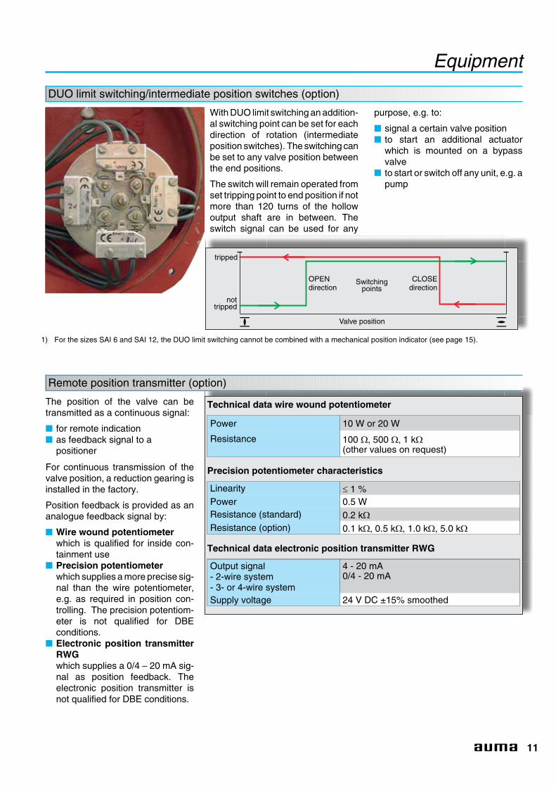
Remote position transmitter (option)
The position of the valve can betransmitted as a continuous signal:
■ for remote indication■ as feedback signal to a
positioner
For continuous transmission of thevalve position, a reduction gearing isinstalled in the factory.
Position feedback is provided as ananalogue feedback signal by:
■ Wire wound potentiometerwhich is qualified for inside con-tainment use
■ Precision potentiometerwhich supplies a more precise sig-nal than the wire potentiometer,e.g. as required in position con-trolling. The precision potentiom-eter is not qualified for DBEconditions.
■ Electronic position transmitterRWGwhich supplies a 0/4 – 20 mA sig-nal as position feedback. Theelectronic position transmitter isnot qualified for DBE conditions.
Technical data wire wound potentiometer
Power 10 W or 20 W
Resistance 100 �� 500 �� 1 k�
(other values on request)
Precision potentiometer characteristics
Linearity � 1 %Power 0.5 WResistance (standard) 0.2 k�
Resistance (option) 0.1 k�� 0.5 k�, 1.0 k�, 5.0 k�
Technical data electronic position transmitter RWG
Output signal- 2-wire system- 3- or 4-wire system
4 - 20 mA0/4 - 20 mA
Supply voltage 24 V DC ±15% smoothed
DUO limit switching/intermediate position switches (option)
With DUO limit switching an addition-al switching point can be set for eachdirection of rotation (intermediateposition switches). The switching canbe set to any valve position betweenthe end positions.
The switch will remain operated fromset tripping point to end position if notmore than 120 turns of the hollowoutput shaft are in between. Theswitch signal can be used for any
purpose, e.g. to:
■ signal a certain valve position■ to start an additional actuator
which is mounted on a bypassvalve
■ to start or switch off any unit, e.g. apump
tripped
Switchingpoints
OPENdirection
CLOSEdirection
Valve position
nottripped
1) For the sizes SAI 6 and SAI 12, the DUO limit switching cannot be combined with a mechanical position indicator (see page 15).

12
Output speeds
Output speeds
With the large range of availableoutput speeds, almost everyrequired operating time can beachieved with AUMA multi-turn actu-ators.
The output speed is determined bythe motor speed and the gear reduc-tion ratios. Therefore it is necessaryto mention the output speed whenplacing an order.
For multi-turn actuators with outputdrive type A, stem nut (refer to page20), the max. permissible stemvelocity (output speed) must beobserved:
■ for gate valves max. 500 mm/min■ for globe valves max. 250 mm/min
(max. 45 rpm)
For higher velocities or outputspeeds it is strongly recommendedto use a spring loaded stem nut, out-put drive type AF (see page 20).
Output speeds n for multi-turn actuators foropen-close duty
Size Torque1)
max.3-phase AC motorShort-time duty
S2 - 10 min
SAI [Nm] n at 50 Hz [rpm]
6 60 4 – 180
12 120 4 – 180
25 250 4 – 180
50 500 4 – 180
100 1 000 4 – 180
Output speeds for multi-turn actuators formodulating duty
Size Torque for modulatingdutymax.
3-phase AC motorIntermittent duty
S4 - 25 % ED
SARI [Nm] n at 50 Hz [rpm]
6 30 4 – 45
12 60 4 – 45
25 120 4 – 45
50 250 4 – 45
100 500 4 – 22
1) Individual sizes have reduced torques at highest speeds

13
Equipment
Motors
3-phase AC motors
As standard AUMA multi-turn actua-tors are equipped with 3-phase ACmotors (TENV, pot-type motor with-out ventilation).
AUMA has developed these motorsto comply with the special require-
ments in valve automation. The mostimportant feature of this design is thehigh starting torque.
For detailed data refer to the techni-cal data sheet ‘Electrical data AUMAmulti-turn actuators SAI 6 – SAI 100’
Torque adjustment
For each actuator ordered, therespective motor is built individually.Therefore, i.e. by the sizing of themotor, it is possible to influence theoutput torque. AUMA also offersactuators whose torques, in devia-tion from the values stated on page8, are adapted to the requirements ofa specific application.
Technical data
3-phase AC motor
Standard voltages 50 Hz: 230 V; 380 V; 400 V; 415 V; 440 V; 475 V; 500 V60 Hz: 440 V; 460 V; 480 V
Permissible variations ± 5 %1)
Motor data Refer to data sheets
Design/mounting IM B14 according to IEC 34-7
Type of motor Squirrel cage
Enclosure protection IP 68
Type of cooling Self-cooling/surface cooling (IC 40 according to IEC 34-6)
Insulation class H according to IEC 85, tropicalized
Electrical connection for motor via terminals or AUMA plug/socket connector
Starting direct
Types of duty S2 - 10 min (SAI) orS4 - 25 % (SARI)
Direction of rotation clockwise and counterclockwise (reversing)
1) Within this range, the actuator reaches the specified torque. Overvoltage may result in excessive temperature rise in the motor windings.The stall torque increases in the ratio of the square of overvoltage divided by the standard voltage. In case of undervoltage the motor torque(stall torque) decreases accordingly with the square of the voltage. If larger voltage variations are stated, they will be taken into accountwhen sizing the actuator.
Tor
que
T
Output speed n
AUMA 3-ph AC motor in modular designwith high starting torque
Standard motor with identical power andlarge size

14
Design principle
MotorAn especially high starting torque isfrequently required to unseat valves
from the end position. The 3-phase ACmotors developed by AUMA fulfil this basicrequirement.Further information on page 13.
Torque switchingThe torque switches are tripped assoon as the set torque has been
reached. This is the prerequisite for torqueseating in one of the end positions. Within thelimits valid for each size, different values canbe specified for each direction. For torqueseating in the end position, the trippingtorque specified by the valve manufacturerhas to be set. In addition the torque switchesprovide protection to the equipment in theevent of excessive torque in mid-travel.
1
GearingThe well proven principle of wormgearing is used to reduce the motor
speed to the required actuator output speed.Worm shaft and output shaft with the wormwheel run in ample sized bearings.
The sliding worm is positioned between twostacks of springs on the worm shaft. Theworm will be moved in relation to the torque.This axial displacement, as a measure forthe torque, is transmitted to the control unitvia lever and gear wheels.
The gear housing is filled with lubricant. Thisresults in maintenance free service for a longperiod of time.
2
3
1
3
4
5
Limit switchingThe limit switching enables limitseating in the end positions. The
switches signal to the actuator controls thatthe set tripping points (end positions) havebeen reached, which then switch off themotor.
4

15
Design principle
6
2 6
8
Mechanical positionindicator (option)
The mechanical position indicator is used toindicate the valve position continuously. Anadditional reduction gearing which reducesthe turns at the output drive to the indicationrange of the position indicator is required.
5
Manual operationFor commissioning or in an emer-gency the multi-turn actuator can be
operated with the handwheel. By operatingthe change-over lever the motor drive is dis-connected and the handwheel engaged.
When starting the motor the manual drive isautomatically disengaged. During electricoperation the handwheel does not rotate.
7
Electrical connectionThe connections for motor and con-trols are either made via terminals or
via a 50-pole AUMA plug/socket connector.
If the plug/socket is disconnected for mainte-nance work, the wiring of the plug/socketconnector remains undisturbed. Further-more, the plug/socket connector is distin-guished from the terminals by the smallersize and a reduced weight.
Further information on page 18.
8
Valve attachmentThe mounting flange is according toEN ISO 5210 or DIN 3210.
Various output drive types are available.Therefore it is possible to adapt to differenttypes of valves.
Further information on page 20.
6

16
Equipment
Bevel gear for handwheel operation
Combinations with part-turn GSI gearboxes
Multi-turn actuators SAIcan be combined with aGSI worm gearbox.
SAI actuators can be combined withGSI worm gearboxes for part-turnvalves applications.
The torque range of these combina-tions is up to 24,000 Nm.
The worm gearboxes are available indifferent versions, e.g. for counter-clockwise closing.
Detailed information can be found onthe corresponding technical datasheets.
The bevel gear for handwheel opera-tion has two advantages:
■ Reduction gearing reduces themanual forces during manual op-eration.
■ If there is not much space avail-able the side-mounted handwheelturned by 90 °may be an asset.
Reduction ratios
SizeSAI/SARI
Reduction ratio
6 2 : 1
12 2 : 1
25 3 : 1
50 3 : 1
100 4 : 1

17
Equipment
Combinations with LEN linear thrust unit
SAI actuators can be combined withthe LEN linear thrust unit for linearvalve applications.
The LEN 12.1 – LEN 200.1 linearthrust units are qualified for outsidecontainment use. SAI/SARI actua-tors in combination with LEN thrustunits have not been submitted forqualification by AUMA. They must betested on a case by case basis by theproject engineer or the end user.
The LEN can be used to generatethrust up to 150 kN and strokes up to100 mm.
Detailed information can be found onthe corresponding technical datasheets.

18
Interfaces
Electrical connection
Terminals
If the use of terminals is stipulated for the electricalconnection, the actuators can be delivered withceramic terminals specially approved and qualifiedfor the use in nuclear power plants. Depending onthe terminal plan of the actuator the required num-ber of terminals are mounted. The terminals aremounted in a frame made of cast iron.
AUMA plug/socket connector (option)
Advantages of this type of connection:
■ Once connected, the wiring remains undisturbeddue to the plug/socket connection, even if the ac-tuator has to be removed from the valve, e.g. formaintenance purposes.
■ Low weight■ Compact size
Parking frame, protection cover (option)
These parts offer the facility to place the plug con-nector, while taken off the actuator, in a safe placeon a wall. The open terminal compartment at theactuator can be closed with the protection cover.This prevents foreign matter, dust and water fromentering the compartment while the plug connectoris removed.

19
Wiring diagrams
T T
S 2DOEL
S 1DSR
S 3WSR
S 4WOEL
24
48
17 18 19 20 21
21
U1 V1 W1 22
22
23
23
M3~
17 18 19 20 24
KSA 9.397
basic equipment
T T
S 2DOEL
S 1DSR
S 3WSR
S 4WOEL
23
489 21
17 22
22
U1 V1 W1 23
23
24
24
R2f1
1
M3~
KSA 9.391
with potentiometer for remote position indication
Technical data
Terminals
Technical data Motor power connections Protective earth Control terminals
Terminals max. 3 1 50Marking U1, V1, W1 according to VDE 1 to 50Voltage max. 750 V – 250 VType of customer connection Screws Screws ScrewsCross section max. 10 mm2 10 mm2 2.5 mm2 flexible, 4 mm2 solid
AUMA plug/socket connector
Technical data Motor power connections1) Protective earth Control pinsNo. of contacts max. 6 (3 are used) 1 (leading contact) 50 pins/socketsMarking U1, V1, W1, U2, V2, W2 according to VDE 1 to 50Voltage max. 750 V – 250 VCurrent max. 25 A – 16 AType of customer connection Screws Screw for ring lug Screws or crimping (option)Cross section max. 6 mm2 6 mm2 2.5 mm2
Material: Pin/socket carrier Ryton Ryton RytonContacts Brass Brass Brass, tin plated or gold plated (option)
Threads for conduit entries2)
■ 2 x Pg 21; 1 x Pg 13.5 or■ 2 x M 25 x 1.5; 1 x M 20 x 1.5
Other thread sizes and thread types, e.g. NPT threads, as well as a different number of threads for conduit entries areavailable on request. Suitable cable glands can be supplied on request if specified beforehand.
1) Suitable for copper wires. For aluminium wires contact AUMA.2) Sealed with plug on delivery
Terminal plans KSA
The electrical equipment of theAUMA multi-turn actuators SAI andSARI is recorded in the KSA terminalplans. The terminal plans show twotypical equipment variants for thestandard version ‘clockwise closing’.
Special wirings according to cus-tomer’s requirements are available.

20
Interfaces
Output drive typesB1, B2 (ISO 5210) or B(DIN 3210)
Output drive for the trans-mission of torques. Valvemounting flange and plugsleeve form a separateunit. Low radial loads canbe accepted.
Output drive typesB3 or B4(ISO 5210) or E (3210)
Bore with keyway for thetransmission of torquesintegrated in the hollowshaft of the actuator.
Output drive type AF(ISO 5210/DIN 3210)
Spring loaded stem nut. Asoutput drive type A, suit-able for rising, non-rotatingvalve stems. By using spe-cial springs it allows a lim-ited axial displacement ofthe stem nut to compen-sate thermal expansion ofthe valve stem or to absorbhigh dynamic loads whenthe valve closes quickly.
Valve attachment
The valve attachment is according toEN ISO 5210 or DIN 3210.
Flange size
Size SAI/SARI 6 12 25 50 100
Torque max. [Nm] 60 120 250 500 1 000
ISO 5210 Standard F10 F10 F14 F14 F16
DIN 3210 Option G0 G0 G1/2 G1/2 G3
Output drive types
Various output drive types accord-ing to EN ISO 5210 or DIN 3210 areavailable in order to adapt themulti-turn actuators to the differenttypes of valves.
Output drive type A(EN ISO 5210/DIN 3210)
Stem nut for rising andnon-rotating valve stems.
The mounting flangetogether with the stem nutand thrust bearings formone assembly, which issuitable for acceptingthrust.

21
Service conditions
Enclosure protection IP 68
As standard, AUMA multi-turn actu-ators SAI and SARI are supplied inenclosure protection IP 68 accordingto EN 60 529.
In order to guarantee the enclosureprotection IP 68, suitable cableglands must be used. They are notpart of the standard supply, but canbe provided by AUMA, if ordered.
Corrosion protection KI/Colour
AUMA multi-turn actuators SAI andSARI and the gearbox range GSI areprovided with the KI corrosion pro-tection which is suitable for use innuclear power plants.
All outside parts as well as the coat-ings are free from aluminium. Beforefinish coating, a 2-component coat-ing based on epoxy resin withmicaeous iron oxide is applied as pri-mary and intermediate coating onthe sand-blasted actuator.
The entire multi-turn actuator iscoated with a decontaminabletwo-component paint based on poly-urethane.
The total film thickness is at least220 µm.
All outside screws are made of stain-less steel.
Colour
The standard colour of the finishcoating is silver-grey (RAL 7001).Optional colours are flame red (RAL3000) and pure white (RAL 9010).
Ambient temperatures/humidity
Types Actuator types Temperature range Max. temperature under DBE conditions
SAI Multi-turn actuators foropen-close duty
– 20 °C .................+ 80 °C under DBE conditions for a short time up to172 °C
SARI Multi-turn actuators for modu-lating duty
– 20 °C .................+ 60 °C under DBE conditions for a short time up to172 °C
Lifetime according to IEEE 382
The minimum lifetime of 2,000 oper-ating cycles for open-close actuatorsstipulated in IEEE 382 was provedfor the multi-turn actuators SAI bymeans of a type test.
Multi-turn actuators for modulating duty SARI
The lifetime in operation hours (h)depends on the load and the numberof starts. A high starting frequencywill rarely improve the modulatingaccuracy. To reach the longest pos-sible maintenance and fault-freeoperation time, the number of startsper hour chosen should be as low aspermissible for the process.
The minimum lifetime of 100,000operating cycles for modulatingactuators stipulated in IEEE 382 wasproved for the multi-turn actuatorsSARI by means of a type test.
Other service conditions
Mounting position
AUMA actuators can be operatedwithout restriction in any mountingposition.
Pressure under DBE conditions
Up to a pressure of 5.6 kg/cm2, thiscorresponds to approx. 0.55 MPaabsolute pressure, the full function-ality of the actuators has beenproved.
Radiation
Up to an integrated radiation dose of2 x 106 Gy (2 x 10⁸ rad) the full func-tionality of the actuators has beenproved.
Vibrations
The actuators are qualified for theOBE (Operating Basis Earthquake,up to 3 g within a frequency range of2 to 35 Hz) and for the SSE (SafeShutdown Earthquake, up to 4.5 gwithin a frequency range of 2 to32 Hz).

Übe
rdru
ckin
bar
Qualification
22
Test procedure
0 1 2 3 4 5 6 7 8 1210 119 2 4 6 8 10 12 14 16 18 20 22 24 4 7 10 13 16 19 22 25 28 31 34
200
80
120
160
40
1
2
3
4
5
6
7
8
9
Load profile for DBE testing
in our example SAI 50(Test report TB-N 79/124)
Test data
Duration: 31 days, 10 hoursRel. humidity: > 95 %Running cycles: 15Spraying: 18 hours, 17 minutesChemical spray: Hydrochloric acid with pH 10.5
and a percentage of 1.6 % boric acidSpraying rate: 12 l/min/m2
Hours Days
TemperaturePressureSprayingRunning cycle
Tem
pera
ture
in°C
Ove
rpre
ssur
ein
bar
Qualification of the multi-turn actuators according to IEEE 382-1978 (Draft)
Selection of the test samples
Production of the test samples
Determination of the output data
Mechanical ageing
■ Thermal ageing
■ Pressure test
■ Radiation
Lifetime test
Vibration tests
■ Simulation of operational vibration
■ OBE (Operating Basis Earthquake)The earthquake which could reasonably be ex-pected to affect the plant site during the operat-ing life of the plant without interrupting the opera-tion of the plant.
■ SSE (Safe Shutdown Earthquake)That earthquake which produces the maximumvibratory ground motion. The capability to shutdown the reactor must be ensured.
DBE testing
Determination of the final data
Functional tests were performed in between the test steps

Übe
rdru
ckin
bar
23
Qualification

24
Other information
EU Directives Functional tests
After assembly, all actuators arethoroughly tested according toAUMA’s inspection specification andthe torque switching is calibrated.
A final inspection record can be pro-vided. The inspection records can beretrieved online via the Internet(www.auma.com).
Quality management
AUMA has a quality managementsystem which is certified accordingto ISO 9001:2000. All internal proce-dures have been defined in the man-agement manual.
Attention to detail and the use of highquality materials are the prerequisitefor long and fault-free operation. Forthis reason, a large number ofchecks and functional tests are inte-grated in the production process.
All production and assembly pro-cesses as well as service work onthe device are fully documented andcan always be reproduced.
CE mark
Since AUMA actuatorscontrols fulfil the require-ments of the Low
Voltage, EMC and the ATEX Direc-
Low Voltage and Electromag-netic Compatibility Directive
AUMA actuators fulfil the require-ments, which has been proved inextensive tests. Therefore AUMAhas issued a Declaration of Confor-mity according to these Directives(on the Internet underwww.auma.com).
Machinery Directive
According to this directive, AUMAactuators, actuator controls andvalve gearboxes are not completemachines. This means that a Certifi-cate of Conformity is not possible.However, AUMA confirms with theDeclaration of Incorporation (on theInternet under www.auma.com) thatduring the design stage the standardsmentioned in the Machinery Directivewere applied.
By mounting the actuator to othercomponents (valves, pipelines etc.)a ‘machine’ within the meaning of theDirective is formed. Before commis-sioning this machine a Certificate ofConformity must be issued.

25
Operational reliability
AUMA SAI and SARI actuators haveproved to be reliable for more than 25years. This is confirmed by the posi-tive response from nuclear powerplant operators as reflected in the fol-lowing letters.

26
Test certificate

27
Index
AAmbient temperatures 21Analogue feedback signal 11Applications 3ATEX 24AUMA plug/ socket connector 18AUMA plug/socket connector 15,19
BBevel gear for handwheel operation 16Bore with keyway 20
CCE mark 24Certificate of Conformity 24Coating 21Colour 21Combinations 16,17Conduit entries 19Control unit 10Corrosion protection 21
DDBE testing 22Declaration of Incorporation 24Definition for multi-turn actuators 4Design principle 14,15DIN 3210 20DUO limit switching 10,11
EElectrical connection 15,18EMC Directive 24EN ISO 5210 20EU 24
FFlange size 20Functional tests 24
GGearing 14
HHammer blow effect 9Handwheel 15Humidity 21
IIndication 10Insulation class 13Intermediate position switches 11Intermittent duty 7
LLifetime 21Limit seating 8Limit switching 8,10,14Linear thrust unit 17Literature 27Low voltage directive> 24
MMachinery Directive 24Manual operation 15Mechanical position indicator 15Modulating duty 7Motors 13,14Mounting position 21
NNumber of starts 7
OOBE (Operating Basis Earthquake)
21,22Open-close duty 6,8,12Operating time 12Output drive 20Output drive types 20Output speeds 12Overload protection 9
PParking frame 18Plug sleeve 20Plug/ socket connector 18Plug/socket connector 15,19Position indicator 10Potentiometer 11Protection cover 18
QQualification 22,23Quality management 24
RReduction gearing 11Reference input signal 7References 25Remote position transmitter 11
SService conditions 21Short-time duty 6,7Single switches 10Speeds 12SSE (Safe Shutdown Earthquake)21,22Stem nut 12,20Summary of functions 5Supply voltage 13Switch rating 10Switches 10,11
TTandem switch 10Technical data 8,12,27Terminal plans 19Terminals 18Thread for conduit entries 19Three-phase AC motor 12,13Torque for modulating 8,12Torque peaks 9Torque seating 8Torque switches 10Torque switching 8,14Torques 8Tripping torque 8Type designation 6Type of duty 6,7,13Type of seating 8
VValve attachment 15,20Vibration test 22
WWiring diagrams 19Worm gearboxes 14,16
Further literature
■ Technical descriptionMulti-turn actuators AUMA NORM SAI 6 - SAI 100according to IEEE 382-1978 (Draft)
■ Technical dataAUMA multi-turn actuators SAI 6 - SAI 100with plug/ socket connector(IEEE 382-1978)
■ Technical dataMulti-turn actuators for modulating dutySARI 6 - SARI 100 with plug/ socket connector(IEEE 382-1978)
■ Electrical dataAUMA multi-turn actuators SAI 6 - SAI 100(IEEE 382-1978)
Index

Certificate Registration No.12 100/104 4269
AUMA Riester GmbH & Co. KGPostfach 1362D - 79373 Mü[email protected]
+49 (0)7631/809-0+49 (0)7631/809 250
EuropeAUMA Riester GmbH & Co. KGPlant MüllheimDE-79373 MüllheimTel +49 7631 809 - [email protected] Ostfildern-NellingenDE-73747 OstfildernTel +49 711 34803 - [email protected] Center CologneDE-50858 KölnTel +49 2234 2037 - [email protected] Center MagdeburgDE-39167 NiederndodelebenTel +49 39204 759 - [email protected] Center BavariaDE-85386 EchingTel +49 81 65 9017- [email protected] Armaturenantriebe GmbHAT-2512 TribuswinkelTel +43 2252 [email protected] (Schweiz) AGCH-8965 BerikonTel +41 566 [email protected] Servopohony spol. s.r.o.CZ-250 01 Brandýs n.L.-St.BoleslavTel +420 326 396 [email protected] AUMATOR ABFI-02230 EspooTel +358 9 5840 [email protected] France S.A.R.L.FR-95157 Taverny CedexTel +33 1 [email protected] ACTUATORS Ltd.GB- Clevedon North Somerset BS21 6THTel +44 1275 [email protected] ITALIANA S.r.l. a socio unicoIT-20023 Cerro Maggiore (MI)Tel +39 0331 [email protected] BENELUX B.V.NL-2314 XT LeidenTel +31 71 581 40 [email protected] Polska Sp. z o.o.PL-41-219 SosnowiecTel +48 32 783 52 [email protected] PRIWODY AUMARU-141400 Khimki, Moscow regionTel +7 495 221 64 [email protected] ARMATUR ABSE-20039 MalmöTel +46 40 [email protected]
GRØNBECH & SØNNER A/SDK-2450 København SVTel +45 33 26 63 [email protected] S.A.ES-28027 MadridTel +34 91 [email protected]. G. Bellos & Co. O.E.GR-13673 Acharnai AthensTel +30 210 [email protected] SØRUM A. S.NO-1300 SandvikaTel +47 [email protected] SintraTel +351 2 1910 95 [email protected] Endüstri Kontrol Sistemieri Tic. Ltd. Sti.TR-06810 AnkaraTel +90 312 217 32 [email protected]
AfricaAUMA South Africa (Pty) Ltd.ZA-1560 SpringsTel +27 11 [email protected] Technique Contrôle CommandeDZ- Bir Mourad Rais AlgiersTel +213 21 56 42 09/[email protected] CairoTel +20 2 23599680 - [email protected]
AmericaAUMA Automação do Brazil ltda.BR- Sao PauloTel +55 11 [email protected] ACTUATORS INC.US-PA 15317 CanonsburgTel +1 724-743-AUMA (2862)[email protected] Chile Representative OfficeCL-9500414 BuinTel +56 2 821 [email protected] S. A.AR-C1140ABP Buenos AiresTel +54 11 4307 [email protected] Inc.CA-L4N 8X1 Barrie OntarioTel +1 705 [email protected] de Colombia Ltda.CO- Bogotá D.C.Tel +57 1 401 [email protected] Procesos y Control AutomáticoEC- QuitoTel +593 2 292 [email protected] International S.A.C.PE- Miralflores - LimaTel +511444-1200 / 0044 / [email protected]
PASSCO Inc.PR-00936-4153 San JuanTel +1 787 [email protected] Maracaibo Estado, ZuliaTel +58 261 7 555 [email protected]
AsiaAUMA Actuators Middle East W.L.L.BH-Salmabad 704Tel + 97 3 [email protected] Actuators (Tianjin) Co., Ltd.CN-300457 TianjinTel +86 22 6625 [email protected] (INDIA) PRIVATE LIMITEDIN-560 058 BangaloreTel +91 80 2839 [email protected] JAPAN Co., Ltd.JP-210-0848 Kawasaki-ku,Kawasaki-shi KanagawaTel +81 44 329 [email protected] ACTUATORS (Singapore) Pte Ltd.SG-569551 SingaporeTel +65 6 [email protected] Ayman Industrial. EqptsAE- DubaiTel +971 4 [email protected] CONTROLS Ltd.HK- Tsuen Wan, KowloonTel +852 2493 [email protected] Controls Co., Ltd.KR-153-702 Gasan-dong,GeumChun-Gu, SeoulTel +82 2 2624 [email protected] Engineering Co WLLKW-22004 SalmiyahTel [email protected] W.L.LQA- DohaTel +974 4350 [email protected] Valves and Intertrade Corp. Ltd.TH-10120 Yannawa BangkokTel +66 2 [email protected]/Top Advance Enterprises Ltd.TW- Jhonghe City Taipei Hsien (235)Tel +886 2 2225 [email protected]
AustraliaBARRON GJM Pty. Ltd.AU-NSW 1570 ArtarmonTel +61 [email protected]
Y003.242/002/en/1.04
For detailed information about AUMA products refer to the Internet:
www.auma.com