Embed Size (px)
Citation preview

REV 7 - A - 2005130935 L-C2-3031
IMPORTANT: READ THESE INSTRUCTIONS CAREFULLY BEFORE STARTING INSTALLATION OR USE.
ELECTRIC GRILL(POST PATIO MOUNT
AND COUNTERTOP MODELS)
E250s & E250t Series
Certified to: ANSI/UL 1026
Robert H. Peterson Co. • 14724 East Proctor Avenue • City of Industry, CA 91746
INSTALLATION INSTRUCTIONS AND OWNER’S MANUAL
INSTALLER: Leave these instructions with consumer.CONSUMER: Retain for future reference.
WARNINGImproper installation, adjustment, alteration, service, or maintenance can cause injury or property damage. For proper installation, refer to the installation instructions. For assistance or additional information, consult a qualified professional service technician or service agency.
Post Patio Mount model
shown
PLEASE READ AND FOLLOW
• Removing permanently affixed rating warning labels WILL void the warranty.
• Observe all local codes and ordinances when installing this appliance. If no local codes are applicable, wire unit in accordance with the latest National Electrical Code, ANSI/NFPA 70, or the Canadian Electrical Code, CSA C22.1, whichever is applicable.
WARNING
To minimize the risk of property damage and/or personal injury, do not use a flexible extension power-supply cord unless it conforms with the specifications as listed in this manual (see IMPORTANT
SAFEGUARDS section).
NOT FOLLOWING THESE INSTRUCTIONS EXACTLY WILL VOID THE MANUFACTURER'S WARRANTY.
WARNINGWhen connecting this appliance to a power supply make sure that it is the same voltage as the unit rating. Improper connection may cause severe damage to the components or decrease the performance of your Fire Magic electric grill. A rating plate specifying voltage, hertz, wattage, and amps is attached to the unit. Also see the IMPORTANT SAFEGUARDS section. To avoid the risk of property damage and/or personal injury, installation work and electrical wiring must be performed by a qualified professional service technician. This appliance must be installed in accordance with this instruction.
SAFETY AND WARNING CODES
US®
C
ONLY TO BE USED OUTDOORS

REV 7 - A - 2005130935 L-C2-303
ELECTRIC GRILL(MODÈLES POST PATIO MONT
ET COUNTERTOP)
Séries E250s et E250t
IMPORTANT: LISEZ CES INSTRUCTIONS SOIGNEUSEMENT AVANT DE COMMENCER L'INSTALLATION OU L'UTILISATION.
INSTRUCTIONS D'INSTALLATION ET MANUEL DU PROPRIÉTAIRE
INSTALLATEUR : Laissez ces instructions avec le consommateur.
CONSOMMATEUR : Maintenez pour la future référence.
2
Certifié à: ANSI/UL 1026
Robert H. Peterson Co. • 14724 East Proctor Avenue • City of Industry, CA 91746
AVERTISSEMENTL'installation inexacte, l'ajustement, le changement, le service, ou l'entretien peuvent causer des dommages ou des dégats matériels. Pour l'installation appropriée, référez-vous aux instructions d'installation. Pour de l'aide ou des renseignements supplémentaires, consulter une agence de technicien de maintenance ou de service professionnel qualifié.
Modèle Post Patio Mont
montré
SVP LISEZ ET SUIVEZ
• L'enlèvement de manière permanente a apposé des avertissements d'étiquette d'estimation videra la garantie.
• Observez tous les codes et ordonnances locaux en installant cet appareil. Si aucun code local n'est applicable, unité de fil selon le plus défunt code électrique national, ANSI/NFPA 70, ou le code électrique canadien, CSA C22.1, celui qui est applicable.
AVERTISSEMENT
Pour réduire au minimum le risque de dégats matériels et/ou de blessures, n'employez pas une prolongation flexible puissance-fournissent la corde à moins qu'elle se conforme aux caractéristiques comme énuméré en ce manuel (voir la section MISES EN GARDE IMPORTANT).
NON SUIVANT CES INSTRUCTIONS EXACTEMENT VIDERONT LA GARANTIE DU FABRICANT.
AVERTISSEMENT
En reliant cet appareil à une alimentation d'énergie assurez-vous que c'est la même tension que l'estimation d'unité. Le raccordement inexact peut endommager considérablement les composants ou diminuer l'exécution de votre gril électrique de Magic du feu. Une plaque de contrôle indiquant la tension, les hertz, la puissance en watts, et les ampères est attachée à l'unité. Voir aussi la section MISES EN GARDE IMPORTANT. Pour éviter le risque de dommages aux biens et / ou des blessures, les travaux d'installation et le câblage électrique doit être effectuée par un technicien de service professionnel qualifié. Cet appareil doit être installé selon cette instruction.
SÛRETÉ ET CODES D'AVERTISSEMENT
US®
C
À UTILISER UNIQUEMENT À L'EXTÉRIEUR

REV 7 - A - 2005130935 L-C2-3033
GETTING STARTED
GETTING STARTEDIMPORTANT SAFEGUARDS ���������������������������������������������������������������������������������������������������������������������4INSTALLATION REQUIREMENTS �����������������������������������������������������������������������������������������������������������6
OVERHEAD CONSTRUCTION REQUIREMENTS ���������������������������������������������������������������������������������������6REAR WALL CLEARANCES ��������������������������������������������������������������������������������������������������������������������7SIDE WALL CLEARANCES (if applicable) ��������������������������������������������������������������������������������������������������7CORNER WALL CLEARANCES (if applicable) ��������������������������������������������������������������������������������������������7COOLING AIRFLOW �����������������������������������������������������������������������������������������������������������������������������8
MODEL SPECIFICATIONS ������������������������������������������������������������������������������������������������������������������������9WIRING DIAGRAM �����������������������������������������������������������������������������������������������������������������������������10
ELECTRIC GRILL REPLACEMENT PARTS LIST ������������������������������������������������������������������������������������11
INSTALLATIONINSTALLATION ��������������������������������������������������������������������������������������������������������������������������������������12
ELECTRICAL SETUP ��������������������������������������������������������������������������������������������������������������������������12COUNTERTOP MODELS ��������������������������������������������������������������������������������������������������������������������12POST PATIO MOUNT MODELS ������������������������������������������������������������������������������������������������������������12CONNECT POWER CORD �������������������������������������������������������������������������������������������������������������������13INSTALL COOKING GRIDS ������������������������������������������������������������������������������������������������������������������13INSTALL WARMING RACK �������������������������������������������������������������������������������������������������������������������13INSTALL ROTISSERIE BRACKET (IF EQUIPPED) �����������������������������������������������������������������������������������13INSTALL DRIP TRAY ���������������������������������������������������������������������������������������������������������������������������14
USE, CARE, & SERVICEDIGITAL THERMOMETER / THERMOSTAT �������������������������������������������������������������������������������������������15OPERATION ��������������������������������������������������������������������������������������������������������������������������������������������18
COOKING ELEMENT �������������������������������������������������������������������������������������������������������������������������18ROTISSERIE (IF EQUIPPED) ���������������������������������������������������������������������������������������������������������������18DROP DOWN SHELVES (if applicable) ���������������������������������������������������������������������������������������������������19
SERVICING AND CLEANING �����������������������������������������������������������������������������������������������������������������20CLEANING YOUR ELECTRIC GRILL �����������������������������������������������������������������������������������������������������20CONTROL PANEL REMOVAL ���������������������������������������������������������������������������������������������������������������22INNER LINER REMOVAL ���������������������������������������������������������������������������������������������������������������������22
TROUBLESHOOTING �����������������������������������������������������������������������������������������������������������������������������23WARRANTY �������������������������������������������������������������������������������������������������������������������������������������������24
CONTENTS

REV 7 - A - 2005130935 L-C2-3034
WARNING!
When using electrical appliances, basic safety precautions must always be followed including the following:
1. Read all instructions.
2. Do not touch hot surfaces, always use the handle.
3. To protect against electrical shock, do not immerse cord, plugs, probe or grill in water or other liquids.
4. Close supervision is necessary when any appliance is used near children.
5. Unplug from outlet when not in use and before cleaning or servicing. Allow to cool before putting on or taking off parts.
Note: After use and shut-off of this unit, DO NOT immediately disconnect the electric supply. The electric fan in this unit will continue to operate so that the unit may completely cool. Always allow sufficient cooling time prior to disconnecting the electric supply.
6. Do not operate appliance with a damaged cord or plug or after the appliance malfunctions or has been damaged in any manner. Return appliance to the nearest authorized service facility for examination, repair or adjustment.
7. The use of accessory attachments not recommended by the appliance manufacturer may cause injuries.
8. Do not let cord hang over edge of table or counter, or touch hot surfaces.
9. Do not place on or near a hot gas or electric burner or in a heated oven.
10. Extreme caution must be used when moving an appliance containing hot oil or other hot liquids.
11. To disconnect, turn any controls to OFF, allow time for the unit to cool completely, then remove plug from wall outlet.
12. Do not use appliance for other than intended use.
13. Fuel, such as charcoal briquettes, is not to be used with appliance.
14. Use only on a properly grounded receptacle:
Use only a properly wired and inspected 120VAC (20 AMP minimum) Ground Fault Circuit Interrupter (GFCI) GROUNDED 3-wire receptacle with this outdoor cooking appliance. The GFCI receptacle must be a WEATHER-PROOF IN-USE COVERED RECEPTACLE. Never remove the grounding plug or use with an adapter of 2 prongs.
15. NEVER grill in the open rain or in standing water as this grill is an electric appliance. There is always a hazard of electric shock while operating this unit.
16. Keep the appliance area clear and free from combustible materials, gasoline, and other flammable vapors. ALL MINIMUM CLEARANCES STATED IN THE INSTALLATION REQUIREMENTS SECTION MUST BE MAINTAINED.
17. This appliance does not contain a fuse or surge protector. The power to the unit must be made readily accessible to the operator through means of a dedicated 20 AMP circuit breaker.
18. The provisions of the National Electric Code as well as any local codes must be observed when installing the product.
19. Store products indoors when not in use - out of reach of children.
IMPORTANT SAFEGUARDS

REV 7 - A - 2005130935 L-C2-3035
IMPORTANTIN THE EVENT OF A GREASE FIRE, IMMEDIATELY UNPLUG THE UNIT (OR TURN OFF THE POWER AT THE SOURCE). KEEP THE LID OPEN AND ALLOW THE FIRE TO EXTINGUISH ITSELF. KEEP AT A SAFE DISTANCE. A THOROUGH INSPECTION BY A QUALIFIED PROFESSIONAL SERVICE TECHNICIAN SHOULD BE CONDUCTED BEFORE FUTURE USE OF YOUR UNIT. THE SERVICE TECHNICIAN WILL CHECK ALL ELECTRICAL WIRING
FOR DAMAGE. ALL WIRING MUST BE REPAIRED PRIOR TO FUTURE USE.
IMPORTANT SAFEGUARDS (cont.)
20. A short power-supply cord is provided to reduce the risk resulting from becoming entangled in or tripping over a longer cord. Extension cords may be used if care is exercised in their use.
If an extension cord is used:
The marked electrical rating of the extension cord should be at least as great as the electrical rating of the appliance. The cord should be arranged so that it will not drape over the countertop or tabletop where it can be pulled on by children or tripped over unintentionally.
Use only 14-gauge extension cords that have a 3-wire grounding plug, are approved for outdoor use, are surface marked with the suffix letter "W", and have a tag stating "suitable for use with outdoor appliances." The length of the cord extension must NOT exceed 25 feet. Examine extension cord before using and replace if damaged. Connection to an extension cord shall be kept dry and off the ground.
21. NEVER cover more than 75% of the cooking or grill surface with griddles or pans. Overheating of the electronic components will occur.
SAVE THESE INSTRUCTIONS
NOTEWHEN INSTALLING AND OPERATING THIS APPLIANCE AS PART OF A PRE-FAB ELECTRIC GRILL ISLAND BUNDLE, ALSO FOLLOW THE
INSTRUCTIONS INCLUDED WITH THE ISLAND.
6
Installation must be performed by a qualified professional service technician.
OVERHEAD CONSTRUCTION REQUIREMENTS
Refer to Fig. 6-1:
• A minimum clearance of 30" is required between the cooking surface and any overhead construction directly above the grill. The construction directly above the grill must have a minimum width of 30".
• A minimum clearance of 18" is required between the countertop (for countertop model) or shelves (for post model) and any overhead construction to the sides of the grill.
• A maximum depth of 13" is permitted for the overhead cabinets.
• It is recommended that the area above the cooking surface of the unit be covered with an exhaust hood.
Fig. 6-1 Overhead requirements
Max. 13"
Min. 18"
Min. 30"
(Countertop model shown)
Min. 30"
INSTALLATION REQUIREMENTS

7
REAR WALL CLEARANCES
The unit must have a minimum clearance of 4" from the rear wall (see Fig. 7-1).
(To allow for proper ventilation and prevent dangerous overheating.)
BACKSPLASH CLEARANCE (if applicable)
If a backsplash exists, it must have a minimum of a 4" clearance from the rear of the unit (to allow for proper ventilation and prevent dangerous overheating). See Fig. 7-2.
Important: This 4" backsplash clearance must first be met prior to any walls beginning behind it.
SIDE WALL CLEARANCES (if applicable)
The unit must have a minimum clearance of 6" from any side walls. See Fig. 7-3.
CORNER WALL CLEARANCES (if applicable)
The unit must have a minimum clearance of 18" from any side walls (to account for variables in airflow that could affect performance). See Fig. 7-4.
Fig. 7-1 Clearance 'A' Diagram
Min. 4"
Fig. 7-2 Backsplash clearance
Backsplash
Min. 4"
(Clearance required for rear wall)
Fig. 7-3 Side wall clearance
Min. 6"Clearances continued on following page
Fig. 7-4 Corner wall clearance
Min. 18"
(Countertop model shown)
For post models, shelves ensure this clearance
For post models, shelves extend
17". Allow 1 additional inch beyond shelf to
meet requirement.
INSTALLATION REQUIREMENTS (Cont.)

8
COOLING AIRFLOW
Proper airflow (front-to-back, Fig. 8-1) MUST be maintained for the unit to perform as it was designed. If airflow is blocked, overheating will result. Do not block the 1" front air inlet along the bottom of the control panel.
CAUTION: Wind blowing into or across the rear oven lid vent (Fig. 8-3) can cause poor performance and/or dangerous overheating. Install the grill so that the prevailing wind blows toward the front of the grill (Fig. 8-2).
CORRECT
PLACE GRILL SO PREVAILING WIND BLOWS TOWARD FRONT
OF GRILL
Fig. 8-2 Airflow direction - CORRECT
(1" front air inlet)
Fig. 8-1 Airflow diagram
YOU MUST PROTECT REAR OVEN VENT FROM
PREVAILING WIND
Rear oven lid vent
INCORRECT
Fig. 8-3 Airflow direction - INCORRECT
INSTALLATION REQUIREMENTS (Cont.)

9
MODEL SPECIFICATIONS
Input electrical requirements 120VAC / 20 AMP minimum / 60 Hz / GFCI outlet *
Cooking element rating 120VAC / 1,800 watts / 15 AMP / 60 Hz
* See IMPORTANT SAFEGUARDS section for important details regarding GFCI outlets and extension cords.
Height Width Depth
Floor to top(with oven) Floor to top
of shelf(C)
Left to right Front to back
Post base(D)
Shelvesup(E)
Shelvesdown(F)
Post base(G)
Maximum outer w/
hood open(H)
Open (A)
Closed (B)
57" 43" 33 1/2" 26" 41 1/4" 22 1/2" 20 1/4" 23"
Fig. 9-1
H
C
G
E
D
B
The grill serial identification number and rating label is located behind the unit.
F
A
Table 1 - Product Specifications
Table 2 - Grill Dimensions - Post Patio Mount Models

10
Note: In addition, a wire diagram can be found affixed to the inside of the control panel.
Digital thermometer / thermostat
WIRING DIAGRAM
Thermometer / Thermostat harness
Fig. 10-1
D
C
B
A
Height Width DepthBase to top (with oven)
Left to right Front to back
Open (A)
Closed(B)
(C)Maximum outer w/
hood open(D)
28" 14” 19" 23"
MODEL SPECIFICATIONS (cont.)
Harness
Power supply
Harness
Thermal switch
Connect to cooking element
Panel mount relay DC brushless fan
Heat shrink tubing butt splice
Ground wire
Power cord
Table 3 - Grill Dimensions - Countertop Models
11
1
16
6
2
4
7
14
5
11
9
12
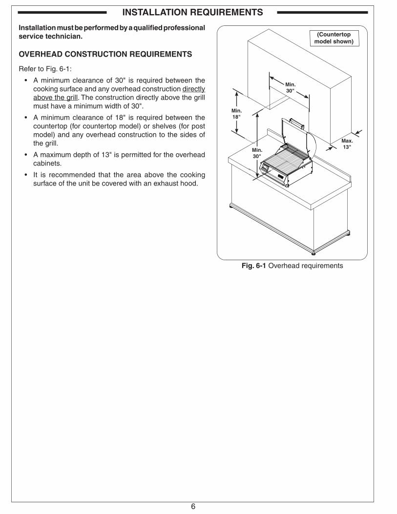
IMPORTANT
Remove all packing material and discard
prior to use.
3
Replacement parts can be ordered from your local Fire Magic® dealer.
13
17
10
Item Description Part No. Qty.
1. Stainless cooking grid (set of 2) 3549-2 1
2. Cooking element 23115-01 1
3. Inner liner kit 23115-02 1
4. Handle assy. 23115-26 1
5. Oven lid 23115-51 1
6. Warming rack 3680 1
7. Digital thermometer/thermostat 23115-12 1
8.Digital thermometer/thermostat wire harness *
23115-13 1
9.Control panel w/ power cord & electronics
23115-07 1
10. Meat probe 24187-14S 1
11. Drip tray 3086 1
12. Bumpers (set of 4) † 23115-09 1
13. Drop down shelf ‡ 25115-015 2
14. Post assy ‡ 25115-03 1
15. Post hardware kit ‡ 24330-25 1
16. Rotisserie kit ▲ 3604S 1
17. Drip tray liners(1 tray included, set of 4 provided at reorder)
3558 1
18. Countertop cover * † ▲ 3642 1
19. Pedestal cover * ‡ ▲ 5115-20 1
* Not shown† Countertop models only‡ Pedestal models only▲ Optional accessory
13
15
ELECTRIC GRILL REPLACEMENT PARTS LIST
12
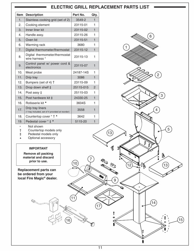
ELECTRICAL SETUPA 120VAC (20 AMP minimum) GFCI GROUNDED 3-wire receptacle (not included) is required within the vicinity of the grill to provide power to the unit. The GFCI receptacle must be a WEATHER-PROOF IN-USE COVERED RECEPTACLE. Your individual installation may vary. Observe the National Electric Code and all local codes.
1. Wire the receptacle into the area of the unit.
• Verify proper polarity of the receptacle.
• If an extension cord is used, ensure it meets all specifications found in the IMPORTANT SAFEGUARDS section.
• DO NOT TAMPER WITH THE EXTENSION CORD OR THE UNIT POWER-SUPPLY CORD.
COUNTERTOP MODELS Be sure the unit is stationed on a clean, dry, and level surface, and that all requirements in the IMPORTANT SAFEGUARDS and INSTALLATION REQUIREMENTS sections are met.
Proceed to the CONNECT POWER CORD section.
POST PATIO MOUNT MODELS
Install the electric grill to the post assembly2. Using a Phillips screwdriver, remove the four screws
and bumpers on the bottom of the grill. Discard the bumpers. See Fig. 12 -2.
3. Align the electric grill onto the top of the post assembly. Using the same four screws, fasten the electric grill to the post assembly. See Fig. 12 -3.
Secure the patio mount grillImportant: Ensure that all requirements in the IMPORTANT
SAFEGUARDS section and INSTALLATION REQUIREMENTS section are met before permanently securing the patio mount grill.
Important: BEFORE USE, the grill base must be securely fastened to a stable, level surface to ensure the grill remains fixed and upright at all times.
1. Locate the patio mount base in the planned grill location and mark the 4 holes. Drill the marked holes to a 1/2" diameter x 1 1/2" depth. Insert the lag shields (see Fig. 12 -3) into the holes, being sure that they are flush with the ground.
2. Align the holes on the patio mount base over the lag shields in the ground. Secure the base with the lag screws (see Fig. 12 -3) using a 7/16" nut driver.
INSTALLATION
INSTALLATION
Fig. 12-1 Electrical setup detail
3-wire GROUNDED cord from unit
(Reference only, DO NOT connect cord at this time)
120VAC (20 AMP minimum) GFCI GROUNDED 3-wire receptacle
Fig. 12-2 Remove bumpers (if applicable)
Fig. 12-3 Post model installation
Remove & discard bumpers
Secure grill to base
Secure base to ground
Lag shields
(PATIO MOUNT MODELS ONLY)

13
Install the drop down shelves
This grill comes with two (2) drop down shelves that must be attached. These can be attached using the four support screws (provided) and a Phillips-head screw driver.
Important: Take caution to not cross-thread when tightening the screws.
1. Remove the four screws on one side of the grill.
2. Align a shelf assembly to the side of the grill.
3. Using the same screws, fasten the shelf to the electric grill. Repeat for the other side.
CONNECT POWER CORD
Route the power cord (coming from the right side of the control panel) to the previously wired 120VAC (20 AMP minimum) GFCI GROUNDED 3-wire receptacle and connect.
INSTALL COOKING GRIDS
Carefully place the cooking grids onto the front and rear grid rests of the unit (see Fig. 13-2).
INSTALL WARMING RACK
Install the warming rack by inserting the two feet through the holes found on the raised walls of the unit (see Fig. 13-2).
INSTALL ROTISSERIE BRACKET (IF EQUIPPED)
If an optional rotisserie has been purchased; the rotisserie bracket must be installed prior to use.
1. Using a Phillips screwdriver; remove the 2 screws located towards the rear, left side of the grill.
2. Locate the correct rotisserie bracket for your installation. Use the small bracket to mount the rotisserie motor. Do not use the large bracket as it is for built-in models only. See Fig. 13-3.
3. Align the holes of the rotisserie bracket with the exposed screw holes on the grill. Using the screws from step 1, fasten the bracket to the grill (see Fig. 13-4).
Reference the ROTISSERIE section for instructions on how to use the rotisserie.
INSTALLATION (cont.)
Fig. 13-1 Install drop down shelves
Shelf support screws
Fig. 13-4 Install bracket (if equipped)
Fig. 13-3 Select rotisserie bracket (if equipped)
DO NOT USE. (For built-in models only)
For Countertop and Post Patio models only
Fig. 13-2 Install cooking grids and warming rack
Cooking grids
Warming rack
Countertop model shown

14
INSTALLATION (cont.)
INSTALL DRIP TRAYYour grill includes a sample drip tray liner. Place the liner into the drip tray as shown in Fig. 14-1, and fully insert the drip tray into the bottom front of the control panel.
Note: Be sure to center the liner in the drip tray, so that it provides complete coverage under all of the openings in the grill.
Fig. 14-1 Install drip tray

15
MENU SET
®
078080170
350TEMP SET ACT
°F
MEAT
OVEN
TIMER 00:00
Fig. 15-3 Default screen detail
Time set via Timer
Meat probe temp. info
Oven temp. info
MENU SET
®
Fig. 15-2 Orientation
Arrows for adjusting digits
SET button for selecting &
confirming
Display screen
Timer button
Menu button
Power button
Your electric grill comes with a digital thermometer/thermostat for temperature control, oven and meat probe temperature monitoring, and timed cooking. Pressing the power button on the thermometer will turn on the grill. Once the grill is turned on, the cooking element immediately begins to heat. Preheating of the grill is required for it to reach the desired cooking temperature. Set the desired temperature as instructed below.
The thermometer will automatically shut off 2 hours from the time the power button is pressed.
For optimal performance, keep the oven lid closed during cooking. This will maintain the cooking temperature. (Frequently opening or leaving the lid open during cooking will result in greater temperature loss.)
The thermometer is located on the left side of the control panel. The actual grill temperature will be maintained within a 20 degree (Fahrenheit) differential of the set temperature.
Plug in the meat probe on the left side of the control panel as shown in Fig. 15-1.
FOR BEST PERFORMANCE, GENTLY PRESS THE BUTTONS. When turned on, accurate temperature readings will begin after the thermometer has initialized. When turned off, allow 5 seconds prior to turning back on.
Read the following sections completely regarding thermometer/thermostat operation. Refer to Fig. 15-2 for thermometer orientation and button locations.
Default ScreenPress the power button to turn the thermometer ON. The default screen will be displayed. Temperatures for the oven and meat probe will be shown (see Fig. 15-3).
Menu ScreenPress the power button to turn the thermometer ON. The default screen will be displayed. Press the MENU button to display its screen. Press the up/down arrow to scroll through the options (see Fig. 15-4).
Note: The menu screen will return to the default screen after approximately 30 seconds of no activity. Press the MENU button to manually return to the default screen.
MENU SET
®
SETUPGRILL GUIDEALARMBACKLIGHT
Fig. 15-4 Menu screen
USE, CARE, & SERVICE
Fig. 15-1 Meat probe detail
MEAT PROBE
Meat probe plug
Meat probe handle
DIGITAL THERMOMETER / THERMOSTAT
16
MENU SET
®
OVEN
ACTUAL: 078 SET TEMP: 350
Fig. 16-1 Area temp. screen (oven shown)
Current location
Set this temp. as desired
Use arrows to set
MENU SET
MEDRARE
WELLDONE
170
170
180
160
N/A
160
150
N/A
150
140
N/A
140
BEEF
PORK
LAMB
PROBETEMP MEDRARE
®
Fig. 16-2 Grill Guide screen
Use arrows to view desired meat
Fig. 16-3 Meat probe
Meat probe
Only check food temperature with
hood open
DO NOT USE MEAT PROBE WITH HOOD CLOSED
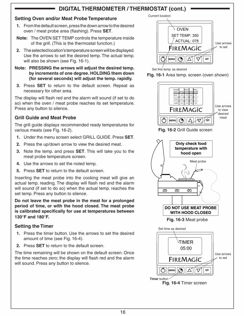
Setting Oven and/or Meat Probe Temperature1. From the default screen, press the down arrow to the desired
oven / meat probe area (flashing). Press SET.
Note: The OVEN SET TEMP controls the temperature inside of the grill. (This is the thermostat function.)
2. The selected location’s temperature screen will be displayed. Use the arrows to set the desired temp. The actual temp. will also be shown (see Fig. 16-1).
Note: PRESSING the arrows will adjust the desired temp. by increments of one degree. HOLDING them down (for several seconds) will adjust the temp. rapidly.
3. Press SET to return to the default screen. Repeat as necessary for other area.
The display will flash red and the alarm will sound (if set to do so) when the oven / meat probe reaches its set temperature. Press any button to silence.
Grill Guide and Meat ProbeThe grill guide displays recommended ready temperatures for various meats (see Fig. 16-2).
1. Under the menu screen select GRILL GUIDE. Press SET.
2. Press the up/down arrow to view the desired meat.
3. Note the temp. and press SET. This will take you to the meat probe temperature screen.
4. Use the arrows to set the noted temp.
5. Press SET to return to the default screen.
Inserting the meat probe into the cooking meat will give an actual temp. reading. The display will flash red and the alarm will sound (if set to do so) when the actual temp. reaches the set temp. Press any button to silence.
Do not leave the meat probe in the meat for a prolonged period of time, or with the hood closed. The meat probe is calibrated specifically for use at temperatures between 130°F and 180°F.
Setting the Timer1. Press the timer button. Use the arrows to set the desired
amount of time (see Fig. 16-4).
2. Press SET to return to the default screen.
The time remaining will be shown on the default screen. Once the time reaches zero; the display will flash red and the alarm will sound. Press any button to silence.
MENU SET
05:00TIMER
®
Fig. 16-4 Timer screen
Set time as desired
Use arrows to set
Timer button
DIGITAL THERMOMETER / THERMOSTAT (cont.)

17
Setting the Alarm (Oven Temp. or Meat Probe)The alarm can be individually set (ON or OFF) for the meat probe and oven temp. The default setting has the alarm OFF for the meat probe and oven temp. The alarm always alerts for the TIMER.
1. Under the menu screen select ALARM. Press SET.
2. Use the up/down arrow to select the desired alarm, and press the power button to turn the alarm ON/OFF.
3. Press SET to return to the menu screen.
4. Press MENU to return to default screen.
Setting the Thermometer BacklightThe default color for the thermometer backlight is blue. The color may be changed as desired by turning the three base colors ON/OFF. Various combinations will result in different colors.
1. Under the menu screen select BACKLIGHT. Press SET.
2. Use the up/down arrow to select the desired color, and press the power button to turn the color ON/OFF.
3. Press SET to return to the menu screen. The new color will now show.
4. Press MENU to return to default screen.
Note: Turning all colors OFF will result in no backlight.
Important: Turn on no more than 2 colors at a time.
Changing Temperature Scale (°C/°F)1. Under the menu screen select SETUP. Press SET.
2. Press SET to select SETUP FC.
3. Select as desired and press SET to return to the menu screen.
4. Press MENU to return to the default screen.
MENU SET
®
OFFON
OVENPROBE
Fig. 17-1 Alarm screen
Press power button to turn colors ON/OFF
Use arrows to select desired alarm
MENU SET
®
OFFOFFON
BACKLIGHTREDGREENBLUE
Fig. 17-2 Backlight screen
Press power button to turn ON/OFF
Use arrows to select desired color
MENU SET
®
TEMPERATURE
FC
Fig. 17-3 Temperature scale screen
Select as desired
DIGITAL THERMOMETER / THERMOSTAT (cont.)

18
COOKING ELEMENT The cooking element may be adjusted between three different heights. Be sure the grill is off and completely cool before any adjustments.
1. Remove the warming rack and cooking grids.
2. Grasp the cool cooking element and apply pressure towards the right of the grill. Once it clears the tab, raise or lower it to the desired height. (See Fig. 18-1.) Be sure it securely rests in position.
3. Replace the cooking grids and warming rack.
Important: To prevent overheating, the cooking element must not come in contact with the thermocouple. A nominal clearance of 1/8" must be maintained at all times. (See Fig. 18-2.)
ROTISSERIE (IF EQUIPPED)Be sure the grill is off and completely cool before beginning rotisserie set up.
1. Remove the warming rack and cooking grids.
2. Adjust the cooking element to the lowest position (if necessary). See COOKING ELEMENT section above for details.
3. Slide the rotisserie motor fully onto the motor bracket located on the left side of the grill (Fig. 18-3).
4. Slide right meat holder into position on rotisserie rod as shown in Fig. 18-4 and tighten screw.
5. Slide meat onto rod and into holder (Figs. 18-4).
Note: To allow proper operation, meat diameters should not exceed 8 inches.
6. Slide left meat holder onto rod and into meat (Fig. 18-4). Tighten thumb screw.
7. Support both ends of the rod so it spins freely. If meat weight is distributed unevenly, the rod will rotate until the heavy side of the meat points downward.
8. Insert the pointed end of the rod into the motor drive socket, and the groove next to the knob into the notch on the right side of the grill.
9. Plug in the rotisserie motor and press the switch to start.
CAUTION: WHEN USING THE ROTISSERIE, KEEP THE OVEN LID CLOSED TO PREVENT HEAT LOSS, PROVIDE PROPER CONVECTION, AND PROVIDE PROPER VENTING. THIS WILL ENSURE EVEN COOKING TEMPERATURES.
DO NOT KEEP YOUR OVEN LID OPEN DURING ROTISSING, AS THIS MAY CAUSE PERSONAL INJURY, OR IN SOME CASES, IN WINDY CONDITIONS, DAMAGE TO THE GRILL.
Reference the DIGITAL THERMOMETER/THERMOSTAT section to begin cooking.
Maintain clearance at all times
(Center meat here)
Leftmeat holder
Rightmeat holder
OPERATION
Fig. 18-1 Adjust cooking element
Fig. 18-2 Thermocouple clearance
Fig. 18-3 Install rotisserie motor
Fig. 18-4 Install meat holders

19
DROP DOWN SHELVES (if applicable)
1. To lower the shelf, grab the middle of the shelf on both sides and lift upward (see Fig. 19-1). Then allow the end of the shelf to rotate down as pictured in Fig. 19-2 and Fig. 19-3.
2. To raise the shelf, grab the middle of the shelf on both sides and raise it to the horizontal position. Lift slightly upward, and lock the shelf safely into position.
CAUTION: Do NOT place fingers near hinge when closing.
OPERATION (cont.)
Fig. 19-1 Shelf up and locked
Fig. 19-2 Being lowered or raised
Fig. 19-3 Shelf down

20
Your electric grill requires regular cleaning and maintenance. Refer to these instructions for details. Performing these procedures will ensure proper operation, appearance, and safety.
WARNINGS• Prior to servicing or cleaning make sure the unit is completely cool, the unit is off, and the power supply is disconnected
(as applicable and unless otherwise stated).
• Wear appropriate gloves and safety glasses during any servicing or cleaning.
• DO NOT spray any cleaner or liquids on the unit when hot.
• The unit MUST be cleaned regularly to prevent grease build-up and other food deposits. A clean and well maintained unit prevents the risk of grease build-up and grease fires.
• Verify proper operation after servicing or deep cleaning.
• See IMPORTANT SAFEGUARDS section for additional related information.
CLEANING YOUR ELECTRIC GRILL
Before Each Use1. Inspect and clean the exterior surfaces of the unit: With a cool grill, clean any dust, grease, splatter, or spills as needed
with a damp clean cloth.
After Each Use1. Clean the cooking grids: Use a grill brush to clean the cooking grids of all residue. Use long-handled insulated BBQ
tools and wear an insulated glove / oven mitt.
Important: The cooking element is self-cleaning (it does not require manual cleaning).
2. Check and clean your drip tray: When the unit is cool, carefully remove the drip tray and dispose of contents appropriately. If tray is equipped with a liner, dispose of the liner. Clean tray in a soapy water solution if needed. For tough deposits, a copper pad can be used. Rinse and dry completely. Replace a new liner and insert the tray back into the electric grill. Order more drip tray liners through your dealer.
3. Cover your grill: Once the unit is dry and cool, cover your grill with a Fire Magic protective cover (not included).
Twice A Year (or as needed) - Deep Clean1. Interior of grill: In addition to cleaning the cooking grids and drip tray, a deep clean of the interior and all components
MUST be performed twice a year (or as needed depending on use). Follow the steps below.
a. With a cool unit, open the oven lid and remove the cooking grids and inner liners. Clean all components in a soapy water solution, rinse, dry, and set aside. For tough deposits, a copper pad can be used. The components can also be cleaned in a dishwasher.
Note: Refer to the parts list and INNER LINER REMOVAL section as needed.
b. Grill inner walls: use a grill cleaner and a copper pad to scrub the inner walls. Fire Magic grill cleaner is recommended. Follow instructions provided with the grill cleaner.
Wipe down the entire surface of the inner walls with a wet, clean, heavy-duty rag. Remove all cleaner.
c. Re-install all components removed during this process.
2. Exterior of grill: With a cool grill, use a grill cleaner (or a soapy water solution) and a clean cloth to remove grease and dirt from the grill exterior. For tough deposits, a copper pad can be used. Always wipe with the grain. Rinse and dry completely. Then follow up with a stainless steel cleaner and a clean cloth.
If this routine cleaning is not performed, the stainless steel may become dull and develop surface rust (due to use and atmospheric conditions). If left uncleaned, significant damage and pitting may occur.
Important: DO NOT use steel wool, any other metal tools, or any other cleaners/chemicals to clean the exterior other than recommended above. Such items promote rust.
Note: Due to the nature of stainless steel, temperatures produced by the cooking process will cause discoloration. This can be reduced by routine cleaning.
SERVICING AND CLEANING
Wipe with grain
Fig. 20-1 Wipe with grain
21
For Environments High In Salt, Chloride, Or Other Corrosive ChemicalsWhen this grill is installed in a corrosive environment such as near the ocean (salt air), poolside (chlorine and/or pool chemicals) or any other location with exposure to high salt/chloride content or corrosive chemicals/solutions, it will be more susceptible to corrosion and MUST be maintained/cleaned more frequently.
• DO NOT store any corrosive chemicals (chlorine, hydrochloric acid, fertilizer, etc.) near your stainless steel unit.
• DO NOT allow any corrosive materials (masonry dust, debris, etc.) to settle on your stainless steel unit.
• These environments, chemicals, and materials may cause the 304 stainless steel to develop surface rust and consequently pitting. Under these conditions the unit exterior MUST be cleaned at least monthly. Inspect your grill often and clean accordingly.
Protecting Your Electric GrillAn optional Fire Magic protective cover will protect your grill when not in use. Install the cover on a cool and dry unit. DO NOT cover a damp grill. During high humidity or after rainy conditions, remove the cover to dry trapped moisture if present. (If the cover is installed over a damp unit it can cause surface rust.)
Ensure that the INSIDE of the cover is DRY before putting it back on the grill.
SERVICING AND CLEANING (cont.)

22
CONTROL PANEL REMOVAL
1. Ensure the grill is completely cool and the power supply is disconnected.
2. Remove the cooking grids and warming rack.
3. Partially slide the drip tray out (to support the control panel when removed).
4. Loosen the nuts underneath the control panel with a 11/32" wrench, then lift the panel until it is freed from the screws. Carefully rest the panel on the drip tray. Reference Fig. 22-1.
Important: When opening, take caution to not damage any wiring.
5. If wire disconnections are required, reference the wire diagram in the MODEL SPECIFICATIONS section in this instruction manual or the wire diagram label affixed to the inside of the control panel.
Note: Secure any disconnected wires (coming from the inside of the unit) to prevent them from falling in.
Note: Whenever reconnecting any wires, apply a small amount of dielectric grease to the male connector, then make the connection. This will ensure conductivity and prevent moisture from affecting the contact.
INNER LINER REMOVAL
1. Ensure the grill is completely cool and the power supply is disconnected.
2. Remove the warming rack and cooking grids.
3. Grasp the cool cooking element and apply pressure towards the right of the grill. Once it clears the tab, completely raise it up (Fig. 22-2).
4. Lift the two side liners up and out (Fig. 22-3).
5. Lift the rear liner slightly up to clear the tab, then forward and out (Fig. 22-4).
6. Move the front liner slightly toward the back of the grill, then lift up and out (Fig. 22-5).
To reinstall, reverse the steps above.
Fig. 22-1 Remove control panel
Loosen nuts to open control panel
Fig. 22-2 Raise element upward
Fig. 22-3 Remove side liners
Fig. 22-4 Remove rear liner
Fig. 22-5 Remove front liner
SERVICING AND CLEANING (Cont.)

23
If you have trouble with the unit, please use this list to identify the problem. By trying one or more of the solutions to the possible cause, you should be able to solve the problem. If this list does not cover your present problem, or if you have other technical difficulties with the unit, please contact your local dealer.
PROBLEM POSSIBLE CAUSE CORRECTION
Grill does not work
1. Power failure
2. Power not plugged correctly
3. GFCI plug may be tripped
1. Check if power is available.
2. Make sure the power cord plug is properly inserted into the receptacle.
3. Reset switches on the GFCI receptacle.
Thermometer does not work
1. No power to unit
2. Faulty component
1. Ensure power is available.
2. Contact your dealer.
Cooking element does not work
1. No power to unit
2. Bad element
1. Ensure power is available.
2. Contact your dealer.
TROUBLESHOOTING

24Robert H. Peterson Co. • 14724 East Proctor Avenue • City of Industry, CA 91746
Quality Check Date:_________________Electrical Leak Test: _____________________ Burn Test: ___________________
Model#: _____________________ Serial#: ___________________
Inspector: _____________________
A COPY OF YOUR SALES SLIP FOR PROOF OF PURCHASE IS REQUIRED
This warranty applies to the original purchaser for products which are installed in the United States or Canada and which are operated and maintained as intended for single family residential usage. This warranty is valid only with proof of purchase, commence on the date of purchase, and terminates (both as to original and any replacement products) on the anniversary date of the original purchase of the product per the above schedules.
This warranty covers defects in material and workmanship. This warranty does not cover parts which become defective as a result of negligence, misuse, use not in compliance with the Installation and Owner’s Manual, accidental damage, improper handling, improper storage, improper installation, lack of required routine maintenance (as specified in the Installation and Owner’s Manual), or electrical damage. Product must be installed as specified in the Installation and Owner’s Manual by a qualified professional installer. Modifications to products which are not specifically authorized will void this warranty. Accessories, parts, valves, remotes, etc. when used must be Peterson products or this warranty is void. Warrantied items will be repaired or replaced at Peterson’s sole discretion. This warranty does not apply to rust, corrosion, oxidation, or discoloration unless the affected part becomes inoperable.
This warranty does not cover labor or labor related charges, except as provided by separate specific written programs from the Peterson Co. All repair work must be performed by a qualified professional service person and requires prior approval of Peterson.
Peterson may require the defective product or part to be returned to the factory to determine the cause of failure. Peterson will pay freight charges if the product or part is determined to be defective. This warranty does not cover breakage in shipment from our (Independent) distributor to its customer if the damage is determined to have occurred during that shipment.
This warranty specifically excludes liability for indirect, incidental, or consequential damages. Some states and provinces do not allow the exclusion or limitation of incidental or consequential damages, so the above exclusion may not apply to you. This warranty gives you specified legal rights, and you may have other rights that vary from state to state or province.
For additional information regarding this warranty, or to place a warranty claim, contact the R. H. Peterson dealer where the product was purchased.
When contacting your Peterson dealer or the R. H. Peterson Co., please provide the following information:
- Your name, address, telephone number, e-mail- Sales receipt showing where purchased and date purchased- Model number, serial number of product, date code- Relevant information: installer, additions, repairs, when defect was first noted
TO REGISTER YOUR PRODUCT ONLINE GO TO: WWW.RHPETERSON.COM,AND CLICK ON PRODUCT REGISTRATION. THANK YOU FOR YOUR PURCHASE.
PETERSON FIRE MAGIC GRILLS AND ACCESSORIES LIMITED WARRANTY
Robert H. Peterson Co. ("RHP") warrants your Fire Magic® grill to be free from defects in material and workmanship.Fire Magic® cast stainless-steel gas burners, Choice stainless steel burners, cooking grids, and barbecue housings are warranted as long as you own your Fire Magic® grill -- LIFETIME. (Except as described below.)Fire Magic® valves, manifold assemblies, inner liners, porcelain housings (including ovens and barbecue faces), and backburner assemblies (except ignition parts) are warranted for FIFTEEN (15) YEARS. Fire Magic® Electric Grills and their stainless steel cooking grids and stainless steel housings are warranted for TEN (10) YEARS.Fire Magic® built-in and portable griddles (except ignition system) are warranted for TEN (10) YEARS.Fire Magic® Infra-red burners, flavor grids, and charcoal stainless steel grills are warranted for FIVE (5) YEARS; except for the charcoal pan, charcoal grid, thermometer, and ash catch tray, which are warranted for ONE (1) YEAR.Fire Magic® sideburners, exterior Glass Fiber Reinforced Concrete (GFRC) grill island systems, and all other grill components (except ignition systems and electronic parts) are warranted for THREE (3) YEARS.Fire Magic® grill and griddle ignition systems (excluding batteries), electronic components (including lights and thermometers), and grill accessories are warranted for ONE (1) YEAR.
WARRANTY