Embed Size (px)
Citation preview

Slide 1 99
wwwnjctlorg
Electric Current amp
DC Circuits
httpnjctliq
Slide 2 99
This material is made freely available at wwwnjctlorg and is intended for the non-commercial use of students and teachers These materials may not be used for any commercial purpose without the written permission of the owners NJCTL maintains its website for the convenience of teachers who wish to make their work available to other teachers participate in a virtual professional learning community andor provide access to course materials to parents students and others
Click to go to websitewwwnjctlorg
New Jersey Center for Teaching and Learning
Progressive Science Initiative
Slide 3 99
How to Use this File
middot Each topic is composed of brief direct instruction
middot There are formative assessment questions after every topic denoted by black text and a number in the upper left
gt Students work in groups to solve these problems but use student responders to enter their own answers
gt Designed for SMART Response PE student response systems
gt Use only as many questions as necessary for a sufficient number of students to learn a topic
middot Full information on how to teach with NJCTL courses can be found at njctlorgcoursesteaching methods
Slide 4 99
Click on the topic to go to that section
middot Circuits
middot Conductors
middot Resistivity and Resistance
middot Circuit Diagrams
Electric Current amp DC Circuits
middot Measurement
httpnjctln3
middot EMF amp Terminal Voltage
middot Kirchhoffs Rules
Slide 5 99
Return toTable ofContents
Circuits
httpnjctln3
Slide 6 99
Electric Current
Electric Current is the rate of flow of electric charges (charge carriers) through space More specifically it is defined as the amount of charge that flows past a location in a material per unit time The letter I is the symbol for current
ΔQ is the amount of charge and Δt is the time it flowed past the location
The current depends on the type of material and the Electric Potential difference (voltage) across it
ΔQ ΔtI =
Slide 7 99
Electric Current
A good analogy to help understand Electric Current is to consider water flow The flow of water molecules is similar to the flow of electrons (the charge carriers) in a wire
Water flow depends on the pressure exerted on the molecules either by a pump or by a height difference such as water falling off a cliff
Electric current depends on the pressure exerted by the Electric Potential difference - the greater the Electric Potential difference the greater the Electric Current
Slide 8 99
The current has the units Coulombs per second
The units can be rewritten as Amperes (A)
1 A = 1 Cs
Amperes are often called amps
ΔQ ΔtI =
Electric Current
httpnjctln3
Slide 9 99
Electric Current
We know that if an Electric Potential difference is applied to a wire charges will flow from high to low potential - a current
However due to a convention set by Benjamin Franklin current in a wire is defined as the movement of positive charges (not the electrons which are really moving) and is called conventional current
Ben didnt do this to confuse future generations of electrical engineers and students It was already known that electrical phenomena came in two flavors - attractive and repulsive - Ben was the person who explained them as distinct positive and negative charges
Slide 10 99
Electric Current
He arbitrarily assigned a positive charge to a glass rod that had been rubbed with silk He could just as easily called it negative - 5050 chance
The glass rod was later found to have a shortage of electrons (they were transferred to the silk) So if the glass rod is grounded the electrons will flow from the ground to the rod
The problem comes in how Electric Potential is defined - charge carriers will be driven from high to low potential - from positive to negative For this to occur in the glass rod - ground system the conventional current will flow from the rod to the ground - opposite the direction of the movement of electrons
Slide 11 99
Electric Current
To summarize - conventional Electric Current is defined as the movement of positive charge In wires it is opposite to the direction of the electron movement
However - in the case of a particle accelerator where electrons are stripped off of an atom resulting in a positively charged ion which is then accelerated to strike a target - the direction of the conventional current is the same as the direction of the positive ions
Slide 12 99
Circuits
An electric circuit is an external path that charges can follow between two terminals using a conducting material
For charge to flow the path must be complete and unbroken
An example of a conductor used to form a circuit is copper wire Continuing the water analogy one can think of a wire as a pipe for charge to move through
httpnjctln3
Slide 13 99
1 12 C of charge passes a location in a circuit in 10 seconds What is the current flowing past the point
httpnjctln4
Slide 13 (Answer) 99
1 12 C of charge passes a location in a circuit in 10 seconds What is the current flowing past the point
httpnjctln4
[This object is a pull tab]
Ans
wer
Slide 14 99
2 A circuit has 3 A of current How long does it take 45 C of charge to travel through the circuit
httpnjctln6
Slide 14 (Answer) 99
2 A circuit has 3 A of current How long does it take 45 C of charge to travel through the circuit
httpnjctln6
[This object is a pull tab]
Ans
wer
Slide 15 99
3 A circuit has 25 A of current How much charge travels through the circuit after 4s
httpnjctln8
Slide 15 (Answer) 99
3 A circuit has 25 A of current How much charge travels through the circuit after 4s
httpnjctln8
[This object is a pull tab]
Ans
wer
Slide 16 99
Batteries
Positive Terminal
Negative Terminal
Each battery has two terminals which are conductors The terminals are used to connect an external circuit allowing the movement of charge
Batteries convert chemical energy to electrical energy which maintains the potential difference
The chemical reaction acts like an escalator carrying charge up to a higher voltage
Click here for a Battery VoltageSimulation from PhET
httpnjctln9
Slide 17 99
Reviewing Basic CircuitsThe circuit cannot have gaps
The bulb had to be between the wire and the terminal
A voltage difference is needed to make the bulb light
The bulb still lights regardless of which side of the battery you place it on
As you watch the videoobservations and
the answers to the questions below
What is going on in the circuit
What is the role of the battery
How are the circuits similar different
Click here for video using thecircuit simulator
from PhET
httpnjctln9
Slide 18 99
The battery pushes current through the circuit A battery acts like a pump pushing charge through the circuit It is the circuits energy source
Charges do not experience an electrical force unless there is a difference in electrical potential (voltage)Therefore batteries have a potential difference between their terminals The positive terminal is at a higher voltage than the negative terminal
Batteries and Current
How will voltage affect currentclick here for a video from
Veritasiums Derek on current
httpnjctln9
Slide 19 99
Return toTable ofContents
Conductors
httpnjctlna
Slide 20 99
Conductors
Some conductors conduct better or worse than others Reminder conducting means a material allows for the free flow of electrons
The flow of electrons is just another name for current Another way to look at it is that some conductors resist current to a greater or lesser extent
We call this resistance R Resistance is measured in ohms which is noted by the Greek symbol omega (Ω)
Click here to run another PhET simulation
How will resistance affect current
httpnjctlna
Slide 21 99
Current vs Resistance amp VoltageRaising resistance reduces currentRaising voltage increases current
We can combine these relationships in what we call Ohms Law
Another way to write this is that
OR V = IR
V
RI =
V
IR =
You can see that one = V
A click here for a Veritasiummusic video on electricity
httpnjctlna
Slide 22 99
4 A flashlight has a resistance of 25 and is connected by a wire to a 120 V source of voltage What is the current in the flashlight
httpnjctlnb
Slide 22 (Answer) 99
4 A flashlight has a resistance of 25 and is connected by a wire to a 120 V source of voltage What is the current in the flashlight
httpnjctlnb
[This object is a pull tab]
Ans
wer
Slide 23 99
5 How much voltage is needed in order to produce a 070 A current through a 490 resistor
httpnjctlne
Slide 23 (Answer) 99
Slide 24 99
6 What is the resistance of a rheostat coil if 005 A of current flows through it when 6 V is applied across it
httpnjctlng
Slide 24 (Answer) 99
6 What is the resistance of a rheostat coil if 005 A of current flows through it when 6 V is applied across it
httpnjctlng
[This object is a pull tab]
Ans
wer
Slide 25 99
Electrical Power
Power is defined as work per unit time
if W = QV then substitute
if then substitute
P = W
t
P = QV
t
I = Q
t P = IV
What happens if the current is increased
What happens if the voltage is decreased
httpnjctlni
Slide 26 99
Electrical Power
Lets think about this another way
The water at the top has GPE amp KE
As the water falls it loses GPE and the wheel gets turned doing workWhen the water falls to the bottom it is now slower having done work
httpnjctlni
Slide 27 99
Electrical Power
Electric circuits are similar
A charge falls from high voltage to low voltage
In the process of falling energy may be used (light bulb run a motor etc)
What is the unit of Power
httpnjctlni
Slide 28 99
Electrical Power
How can we re-write electrical power by using Ohms Law
P = IV(electrical power)
I = V R
(Ohms Law)
P = VV R
P = V2
R
httpnjctlni
Slide 29 99
Is there yet another way to rewrite this
P = IV(electrical power)
V = I R(Ohms Law)
P = I(IR)
P = I2R
We can substitute this into Power
I = V can be rewritten as V = IR R
Electrical Power
httpnjctlni
Slide 30 99
D C AAA AA 9 V
15 V
D C AA amp AAA have the same voltage however they differ in the amount of power they deliver
For instance D batteries can deliver more current and therefore more power
Batteries
httpnjctlni
Slide 31 99
7 A toy cars electric motor has a resistance of 17 find the power delivered to it by a 6-V battery
httpnjctlnj
Slide 31 (Answer) 99
7 A toy cars electric motor has a resistance of 17 find the power delivered to it by a 6-V battery
httpnjctlnj
[This object is a pull tab]
Ans
wer
Slide 32 99
8 What is the power consumption of a flash light bulb that draws a current of 028 A when connected to a 6 V battery
httpnjctlnl
Slide 32 (Answer) 99
8 What is the power consumption of a flash light bulb that draws a current of 028 A when connected to a 6 V battery
httpnjctlnl
[This object is a pull tab]
Ans
wer
Slide 33 99
9 A 30Ω toaster consumes 560 W of power how much current is flowing through the toaster
httpnjctlnn
Slide 33 (Answer) 99
Slide 34 99
10 When 30 V is applied across a resistor it generates 600 W of heat what is the magnitude of its resistance
httpnjctlnp
Slide 34 (Answer) 99
10 When 30 V is applied across a resistor it generates 600 W of heat what is the magnitude of its resistance
httpnjctlnp
[This object is a pull tab]
Ans
wer
Slide 35 99
Return toTable ofContents
Resistivity and Resistance
httpnjctlnr
Slide 36 99
Pipe size
How could the wire in the circuit affect the current
If wire is like a pipe and current is like water that flows through the pipe
if there were pipes with water in them what could we do to the pipes to change the speed of the water (the current)
httpnjctlnr
Slide 36 (Answer) 99
Pipe size
How could the wire in the circuit affect the current
If wire is like a pipe and current is like water that flows through the pipe
if there were pipes with water in them what could we do to the pipes to change the speed of the water (the current)
httpnjctlnr
Ans
wer
change the cross-sectional area of the pipe
making it bigger will allow more water to flow
change the length of the pipeincreasing the length will increase the time it takes for the water to get to the end of its trip
Slide 37 99
Resistivity amp ResisitanceEvery conductor conducts electric charge to a greater or lesser extent
The last example also applies to conductors like copper wire Decreasing the length (L) or increasing the cross-sectional area (A) would increase conductivity
Also the measure of a conductors resistance to conduct is called its resistivity Each material has a different resistivity
Resistivity is abbreviated using the Greek letter rho ()
Combining what we know about A L and ρ we can find a conductors total resistance
R = L A
httpnjctlnr
Slide 38 99
Resistivity amp Resisitance
Resistance R is measured in Ohms (Ω) Ω is the Greek letter Omega
Cross-sectional area A is measured in m2
Length L is measured in m
Resistivity ρ is measured in Ωm
R = L A
How can we define A for a wire
httpnjctlnr
Slide 39 99
Resisitance
What is the resistance of a good conductor
Low low resistance means that electric charges are free to move in a conductor
= RA L
Click here for a PhETsimulation about Resistance
httpnjctlnr
Slide 40 99
Resistivities of Common Conductors
Resistivity (10-8 Ωm)MaterialSilver
Copper
Gold
Aluminum
Tungsten
Iron
Platinum
Mercury
Nichrome
159
168
244
265
560
971
106
98
100
Slide 41 99
11 Rank the following materials in order of best conductor to worst conductor
A Iron Copper Platinum
B Platinum Iron Copper
C Copper Iron Platinum
Resistivity (10-8 Ωm)MaterialSilver
Copper
Gold
Aluminum
Tungsten
Iron
Platinum
Mercury
Nichrome
159
168
244
265
560
971
106
98
100
httpnjctlnr
Slide 41 (Answer) 99
11 Rank the following materials in order of best conductor to worst conductor
A Iron Copper Platinum
B Platinum Iron Copper
C Copper Iron Platinum
Resistivity (10-8 Ωm)MaterialSilver
Copper
Gold
Aluminum
Tungsten
Iron
Platinum
Mercury
Nichrome
159
168
244
265
560
971
106
98
100
httpnjctlnr
[This object is a pull tab]
Ans
wer
C
Slide 42 99
12 What is the resistance of a 2 m long copper wire whose cross-sectional area of 02 mm2
httpnjctlns
Slide 42 (Answer) 99
Slide 43 99
13 An aluminum wire with a length of 900 m and cross-sectional area of 10 mm 2 has a resistance of 25 What is the resistivity of the wire
httpnjctlnt
Slide 43 (Answer) 99
13 An aluminum wire with a length of 900 m and cross-sectional area of 10 mm 2 has a resistance of 25 What is the resistivity of the wire
httpnjctlnt
[This object is a pull tab]
Ans
wer
Slide 44 99
14 What diameter of 100 m long copper wire would have a resistance of 010
httpnjctlnu
Slide 44 (Answer) 99
14 What diameter of 100 m long copper wire would have a resistance of 010
httpnjctlnu
[This object is a pull tab]
Ans
wer
Slide 45 99
15 What is the length of a 10 Ω copper wire whose diameter is 32 mm
pI4oFdjExZE+++TI-Tmp-njctl_a
Slide 45 (Answer) 99
15 What is the length of a 10 Ω copper wire whose diameter is 32 mm
pI4oFdjExZE+++TI-Tmp-njctl_a
[This object is a pull tab]
Ans
wer
Slide 46 99
16 The length of a copper wire is cut to half By what factor does the resistance change
pI4oFdjExZE+++TI-Tmp-njctl_a
A 14B 12C 2D 4
Slide 46 (Answer) 99
16 The length of a copper wire is cut to half By what factor does the resistance change
pI4oFdjExZE+++TI-Tmp-njctl_a
A 14B 12C 2D 4
[This object is a pull tab]
Ans
wer
B
Slide 47 99
17 The radius of a copper wire is doubled By what factor does the resistivity change
pI4oFdjExZE+++TI-Tmp-njctl_a
A 14B 12C 1D 2
Slide 47 (Answer) 99
17 The radius of a copper wire is doubled By what factor does the resistivity change
pI4oFdjExZE+++TI-Tmp-njctl_a
A 14B 12C 1D 2
[This object is a pull tab]
Ans
wer
C
Slide 48 99
Return toTable ofContents
Circuit Diagrams
pI4oFdjExZE+++TI-Tmp-njctl_a
Slide 49 99
Circuit Diagrams
Drawing realistic pictures of circuits can be very difficult For this reason we have common symbols to represent each piece
Resistor Battery Wire
Note Circuit diagrams do not show where each part is physically located
pI4oFdjExZE+++TI-Tmp-njctl_a
Slide 50 99
Circuit Diagrams
Draw a simple circuit that has a 9 V battery with a 3 Ω resistor across its terminals What is the magnitude and direction of the current
Conventional current flows from the positive terminal to the negative terminal
pI4oFdjExZE+++TI-Tmp-njctl_a
Slide 50 (Answer) 99
Circuit Diagrams
Draw a simple circuit that has a 9 V battery with a 3 Ω resistor across its terminals What is the magnitude and direction of the current
Conventional current flows from the positive terminal to the negative terminal
pI4oFdjExZE+++TI-Tmp-njctl_a
[This object is a pull tab]
Ans
wer
R = 3
V = 9 V
II = 3A
Slide 51 99
There are two ways to add a second resistor to the circuit
R1 R2
V
R1
R2
V
Series Parallel
All charges must move through both resistors to get to the negative
terminal
Charges pass through either R1 or R2 but not both
Circuit Diagrams
pI4oFdjExZE+++TI-Tmp-njctl_a
Slide 52 99
Are the following sets of resistors in series or parallelR1
R2
V
R1
R2V
Circuit Diagrams
pI4oFdjExZE+++TI-Tmp-njctl_a
Slide 52 (Answer) 99
Are the following sets of resistors in series or parallelR1
R2
V
R1
R2V
Circuit Diagrams
pI4oFdjExZE+++TI-Tmp-njctl_a
[This object is a pull tab]
Ans
wer
SeriesParallelThe test is to trace the shortest route around the circuit The resistors found on the same route are in series those not found on the same route are in parallel to those that were
Slide 53 99
Equivalent Resistance
Resistors and voltage from batteries determine the current
Circuits can be redrawn as if there were only a single resistor and batteryBy reducing the circuit this way the circuit becomes easier to study
The process of reducing the resistors in a circuit is called finding the equivalent resistance (Req)
R1 R2
V
pI4oFdjExZE+++TI-Tmp-njctl_a
Slide 54 99
Series Circuits Equivalent Resistance
What happens to the current in the circuit to the right
R1 R2
V
pI4oFdjExZE+++TI-Tmp-njctl_a
Slide 54 (Answer) 99
Series Circuits Equivalent Resistance
What happens to the current in the circuit to the right
R1 R2
V
pI4oFdjExZE+++TI-Tmp-njctl_a
[This object is a pull tab]
Ans
wer The current passing through
all parts of a series circuit is the same For example I = I1 = I2
Slide 55 99
Series Circuits Equivalent Resistance
What happens to the voltage as it moves around the circuit
R1 R2
V
pI4oFdjExZE+++TI-Tmp-njctl_a
Slide 55 (Answer) 99
Series Circuits Equivalent Resistance
What happens to the voltage as it moves around the circuit
R1 R2
V
pI4oFdjExZE+++TI-Tmp-njctl_a
[This object is a pull tab]
Ans
wer
The sum of the voltage drops across each of the resistors in a series circuit equals the voltage of the battery
For example V = V1 + V2
Slide 56 99
If V = V1 + V2 + V3 +
IR = I1R1 + I2R2 + I3R3
IR = IR1 + IR2 + IR3
Req = R1 + R2 + R3 +
To find the equivalent resistance (Req) of a series circuit add the resistance of all the resistorsIf you add more resistors to a series circuit what happens to the resistance
Series Circuits Equivalent Resistance
substitute Ohms Law solved for V is V = IR
but since current (I) is the same everywhere in a series circuit
I = I1 = I2 = I3
Now divide by I
pI4oFdjExZE+++TI-Tmp-njctl_a
Slide 57 99
18 What is the equivalent resistance in this circuit
R1 = 5 R2 = 3
V = 9 V
httpnjctlnw
Slide 57 (Answer) 99
18 What is the equivalent resistance in this circuit
R1 = 5 R2 = 3
V = 9 V
httpnjctlnw
[This object is a pull tab]
Ans
wer Resistors in series
Slide 58 99
19 What is the total current at any spot in the circuit
R1 = 5 R2 = 3
V = 9 V
httpnjctlnx
Slide 58 (Answer) 99
19 What is the total current at any spot in the circuit
R1 = 5 R2 = 3
V = 9 V
httpnjctlnx
[This object is a pull tab]
Ans
wer
Resistors in series
Slide 59 99
20 What is the voltage drop across R1
R1 = 5 R2 = 3
V = 9 V
httpnjctlny
Slide 59 (Answer) 99
20 What is the voltage drop across R1
R1 = 5 R2 = 3
V = 9 V
httpnjctlny
[This object is a pull tab]
Ans
wer
Resistors in series
Net Currentequal everywhere
Voltage Drop across R1
Slide 60 99
hint A good way to check your work is to see if the voltage drop across all resistors equals the total voltage in the circuit
21 What is the voltage drop across R2
R1 = 5 R2 = 3
V = 9 V
httpnjctlnz
Slide 60 (Answer) 99
hint A good way to check your work is to see if the voltage drop across all resistors equals the total voltage in the circuit
21 What is the voltage drop across R2
R1 = 5 R2 = 3
V = 9 V
httpnjctlnz
[This object is a pull tab]
Ans
wer
Net Currentequal everywhereResistors in series
Voltage Drop across R2
Slide 61 99
22 How much power is used by R1
R1 = 5 R2 = 3
V = 9 V
httpnjctlo0
Slide 61 (Answer) 99
Slide 62 99
Parallel Circuits Equivalent Resistance
What happens to the current in the circuit to the right
R1
R2
V
httpnjctlo5
Slide 62 (Answer) 99
Parallel Circuits Equivalent Resistance
What happens to the current in the circuit to the right
R1
R2
V
httpnjctlo5
[This object is a pull tab]
Ans
wer
The sum of the currents through each of the resistors in a parallel circuit equals the current of the battery
For example I = I1 + I2
Slide 63 99
Parallel Circuits Equivalent Resistance
What happens to the voltage as it moves around the circuit
R1
R2
V
httpnjctlo5
Slide 63 (Answer) 99
Parallel Circuits Equivalent Resistance
What happens to the voltage as it moves around the circuit
R1
R2
V
httpnjctlo5
[This object is a pull tab]
Ans
wer The voltage across all the
resistors in a parallel circuit is the same
For example V = V1 = V2
Slide 64 99
If I = I1 + I2 + I3
V1
R1
VR
V3
R3
V2
R2++=
VR1
VR
VR3
VR2
++=
1R1
VR
1R3
1R2
++= V( (
1R1
1Req
1R3
1R2
++=
If you add more resistors in parallel what will happen to the resistance of the circuit
Rewrite Ohms Law for I and substitute for each resistor
Also since V = V1 = V2 = V3 so we can substitute V for any other voltage
Voltage is a common factor so factor it out
Divide by V to eliminate voltage from the equation
Parallel Circuits Equivalent Resistance
httpnjctlo5
Slide 65 99
23 What is the equivalent resistance in the circuit
R1 = 3
R2 = 6
V = 18V
httpnjctlo6
Slide 65 (Answer) 99
23 What is the equivalent resistance in the circuit
R1 = 3
R2 = 6
V = 18V
httpnjctlo6
[This object is a pull tab]
Ans
wer
Slide 66 99
24 What is the voltage at any spot in the circuit
R1 = 3
R2 = 6
V = 18V
httpnjctlo7
Slide 66 (Answer) 99
24 What is the voltage at any spot in the circuit
R1 = 3
R2 = 6
V = 18V
httpnjctlo7
[This object is a pull tab]
Ans
wer
18 V
Slide 67 99
25 What is the current through R1
R1 = 3
R2 = 6
V = 18V
httpnjctlo8
Slide 67 (Answer) 99
25 What is the current through R1
R1 = 3
R2 = 6
V = 18V
httpnjctlo8
[This object is a pull tab]
Ans
wer
Slide 68 99
26 What is the current through R2
R1 = 3
R2 = 6
V = 18V
httpnjctlo9
Slide 68 (Answer) 99
26 What is the current through R2
R1 = 3
R2 = 6
V = 18V
httpnjctlo9
[This object is a pull tab]
Ans
wer
Slide 69 99
27 What is the power used by R1
R1 = 3
R2 = 6
V = 18V
httpnjctloa
Slide 69 (Answer) 99
27 What is the power used by R1
R1 = 3
R2 = 6
V = 18V
httpnjctloa
[This object is a pull tab]
Ans
wer
Power used by R1
Slide 70 99
28 What is the power used by R2
R1 = 3
R2 = 6
V = 18V
httpnjctlob
Slide 70 (Answer) 99
28 What is the power used by R2
R1 = 3
R2 = 6
V = 18V
httpnjctlob
[This object is a pull tab]
Ans
wer
Power used by R2
Slide 71 99
29 What is the total current in this circuit
R1 = 3
R2 = 6
V = 18V
R3 = 4
httpnjctlob
Slide 71 (Answer) 99
29 What is the total current in this circuit
R1 = 3
R2 = 6
V = 18V
R3 = 4
httpnjctlob
[This object is a pull tab]
Ans
wer
Slide 72 99
30 What is the voltage drop across the third resistor
R1 = 3
R2 = 6
V = 18V
R3 = 4
httpnjctlob
Slide 72 (Answer) 99
30 What is the voltage drop across the third resistor
R1 = 3
R2 = 6
V = 18V
R3 = 4
httpnjctlob
[This object is a pull tab]
Ans
wer
Slide 73 99
31 What is the current though the first resistor
R1 = 3
R2 = 6
V = 18V
R3 = 4
httpnjctlob
Slide 73 (Answer) 99
31 What is the current though the first resistor
R1 = 3
R2 = 6
V = 18V
R3 = 4
httpnjctlob
[This object is a pull tab]
Ans
wer
Slide 74 99
Return toTable ofContents
Measurement
httpnjctloh
Slide 75 99
Voltmeter
Voltage is measured with a voltmeter Voltmeters are connected in parallel and measure the difference in potential between two points
Since circuits in parallel have the same voltage and a voltmeter has very high resistance very little current passes through it
This means that it has little effect on the circuit
httpnjctloh
Slide 76 99
Ammeter
Current is measured using an ammeter
Ammeters are placed in series with a circuit In order to not interfere with the current the ammeter has a very low resistance
httpnjctloh
Slide 77 99
Multimeter
Although there are separate items to measure current and voltage there are devices that can measure both (one at a time)
These devices are called multimetersMultimeters can also measure resistance
Click here for a PhETsimulation on circuits
httpnjctloh
Slide 78 99
L
32 A group of students prepare an experiment with electric circuits Which of the following diagrams can be used to measure both current and voltage
A B
C D
E
httpnjctloi
Slide 78 (Answer) 99
L
32 A group of students prepare an experiment with electric circuits Which of the following diagrams can be used to measure both current and voltage
A B
C D
E
httpnjctloi
[This object is a pull tab]
Ans
wer
E
Slide 79 99
Return toTable ofContents
EMF amp Terminal Voltage
httpnjctloh
Slide 80 99
Electromotive Force
Req
Er
_+
A battery is a source of voltage AND a resistor
Each battery has a source of electromotive force and internal resistance
Electromotive force (EMF) is the process that carries charge from low to high voltage
Another way to think about it is that EMF is the voltage you measure when no resistance is connected to the circuit
httpnjctloj
Slide 81 99
Req
Er
_+
Terminal voltage (VT) is the voltage measured when a voltmeter is across its terminals
If there is no circuit attached no current flows and the measurement will equal the EMF
Electromotive Force
If however a circuit is attached the internal resistance will result in a voltage drop and a smaller terminal voltage (E - Ir)
httpnjctloj
Slide 82 99
Req
Er
_+
We say that the terminal voltage is
VT = E - Ir
Maximum current will occur when there is zero external current
When solving for equivalent resistance in a circuit the internal resistance of the battery is considered a series resistor
REQ = Rint + Rext
Terminal Voltage
httpnjctloj
Slide 83 99
33 When the switch in the circuit below is open the voltmeter reading is referred to as
A EMFB CurrentC PowerD Terminal VoltageE Restivity
httpnjctlok
Slide 83 (Answer) 99
33 When the switch in the circuit below is open the voltmeter reading is referred to as
A EMFB CurrentC PowerD Terminal VoltageE Restivity
httpnjctlok
[This object is a pull tab]
Ans
wer
A
Slide 84 99
34 When the switch in the circuit below is closed the voltmeter reading is referred to as
A Terminal VoltageB EMFC CurrentD ResistanceE Power
httpnjctlol
Slide 84 (Answer) 99
34 When the switch in the circuit below is closed the voltmeter reading is referred to as
A Terminal VoltageB EMFC CurrentD ResistanceE Power
httpnjctlol
[This object is a pull tab]
Ans
wer
A
Slide 85 99
35 A 6V battery whose internal resistance 15 Ω is connected in series to a light bulb with a resistance of 68 Ω What is the current in the circuit
httpnjctlom
Slide 85 (Answer) 99
Slide 86 99
36 A 6V battery whose internal resistance 15Ω is connected in series to a light bulb with a resistance of 68Ω What is the terminal voltage of the battery
httpnjctlon
Slide 86 (Answer) 99
Slide 87 99
37 A 25 Ω resistor is connected across the terminals of a battery whose internal resistance is 06 Ω What is the EMF of the battery if the current in the circuit is 075 A
httpnjctloo
Slide 87 (Answer) 99
Slide 88 99
Return toTable ofContents
Kirchhoffs Rules
httpnjctloh
Slide 89 99
Up until this point we have been analyzing simple circuits by combining resistors in series and parallel and using Ohms law
This works for simple circuits but in order analyze more complex circuits we need to use Kirchhoffs Rules which are based on the laws of conservation of charge and energy
Kirchhoffs Rules
Slide 90 99
Kirchhoffs First rule or junction rule is based on the law of conservation of charge It states
At any junction point the sum of all currents entering the junction point must equal the sum of all the currents exiting the junction
For example
I1 + I2 = I3
Kirchhoffs Rules
I1
I2I3
Slide 91 99
Kirchhoffs Second rule or loop rule is based on the law of conservation of energy It states
The sum of all changes in potential around any closed path must equal zero
For example
The sum of the voltage drops is equal to the voltage across the battery
V - V1 - V2 =0 OR V = V1 + V2
Kirchhoffs Rules
V
V1 V2
Slide 92 99
1 Label + and - for each battery
2 Label the current in each branch with a symbol and an arrow (Dont worry about the direction of the arrow It its incorrect the solution will be negative)
3 Apply the junction rule to each junction You need as many equations as there are unknowns (You can also use Ohms Law to reduce the number of unknowns)
4 Apply the loop rule for each loop (Pay attention to signs For a resistor the potential difference is negative For a battery the potential difference is positive)
5 Solve the equations algebraically
Problem Solving with Kirchhoffs Rules
Slide 93 99
Find the unknowns in the following circuit
Problem Solving with Kirchhoffs Rules
R1 = 5 R2 = 3
V = 12 V
R3 = R4 = 2V3 = 187 V
I2 = 26 A
Slide 94 99
Problem Solving with Kirchhoffs Rules
R1 = 5 R2 = 3
V = 12 V
R3 = R4 = 2
I2 = 26 A
V3 = 187 V
+ _
First label + and - for each battery
Slide 95 99
Next label the current in each branch with a symbol and an arrow
Problem Solving with Kirchhoffs Rules
R1 = 5 R2 = 3
V = 12 V
R3 = R4 = 2
I2 = 26 A
V3 = 187 V
+ _
I3 I4
I
I1
Slide 96 99
Next apply the junction rule to each junction
Problem Solving with Kirchhoffs Rules
R1 = 5 R2 = 3
V = 12 V
R3 = R4 = 2
I2 = 26 A
V3 = 187 V
+ _
I3 I4
I
I1
Slide 96 (Answer) 99
Next apply the junction rule to each junction
Problem Solving with Kirchhoffs Rules
R1 = 5 R2 = 3
V = 12 V
R3 = R4 = 2
I2 = 26 A
V3 = 187 V
+ _
I3 I4
I
I1
[This object is a pull tab]
Ans
wer I = I3 + I4
= I2
I1 = I3
Slide 97 99
Next apply the loop rule to each loop
Problem Solving with Kirchhoffs Rules
R1 = 5 R2 = 3
V = 12 V
R3 = R4 = 2
I2 = 26 A
V3 = 187 V
+ _
I3 I4
I1
I
I = I3 + I4
I = I2
I1 = I3
Slide 97 (Answer) 99
Next apply the loop rule to each loop
Problem Solving with Kirchhoffs Rules
R1 = 5 R2 = 3
V = 12 V
R3 = R4 = 2
I2 = 26 A
V3 = 187 V
+ _
I3 I4
I1
I
I = I3 + I4
I = I2
I1 = I3
[This object is a pull tab]
Ans
wer
V = V3 + V1 + V2
V = V4 + V2
V1 + V3 = V4
Slide 98 99
Problem Solving with Kirchhoffs Rules
V = V3 + V1 + V2
V = V4 + V2
V1 + V3 = V4
I = I3 + I4
I = I2
I1 = I3
Current (Amps) Voltage (Volts) Resistance (Ohms)
R1 5
R2 26 3
R3 187
R4 2
Total 12
List the givens and use ohms law to solve for the unknowns
Ans
wer
Slide 99 99
Find the unknowns in the following circuit
Problem Solving with Kirchhoffs Rules
V = 120 V
R1 = 10
I1 = 7 A
V1 = 70 V
R3 = 2
I3 = 10 A
V3 = 20 V
R4 = 3
I4 = 10 A
V4 = 30 V
R2 = 23
I2 = 3 A
V2 = 70 V
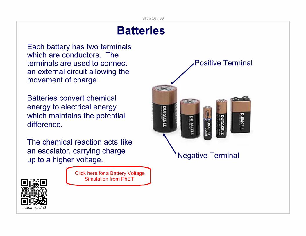
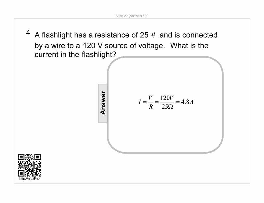
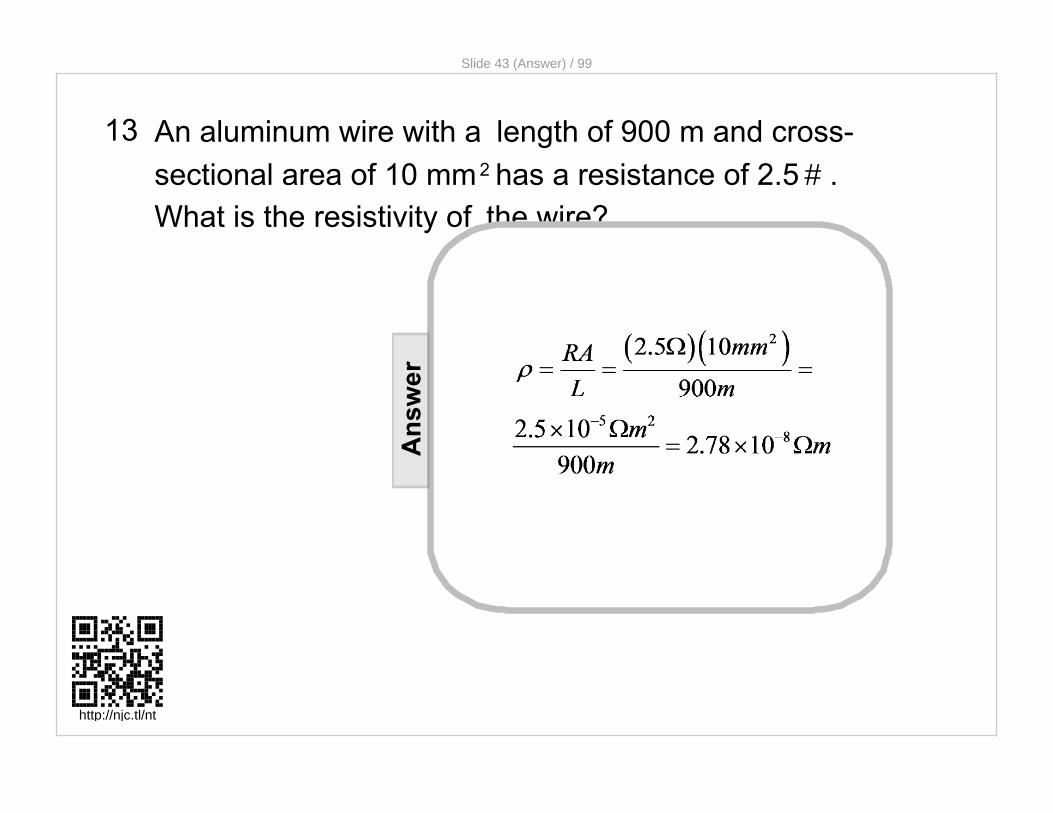
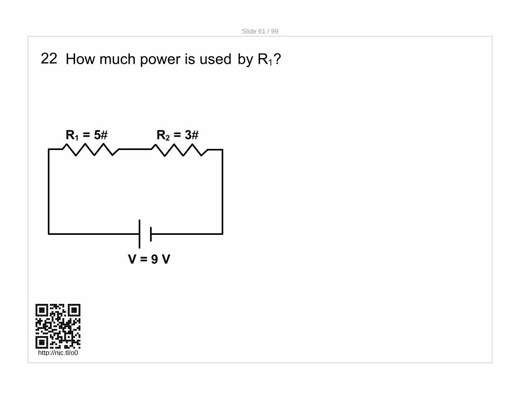
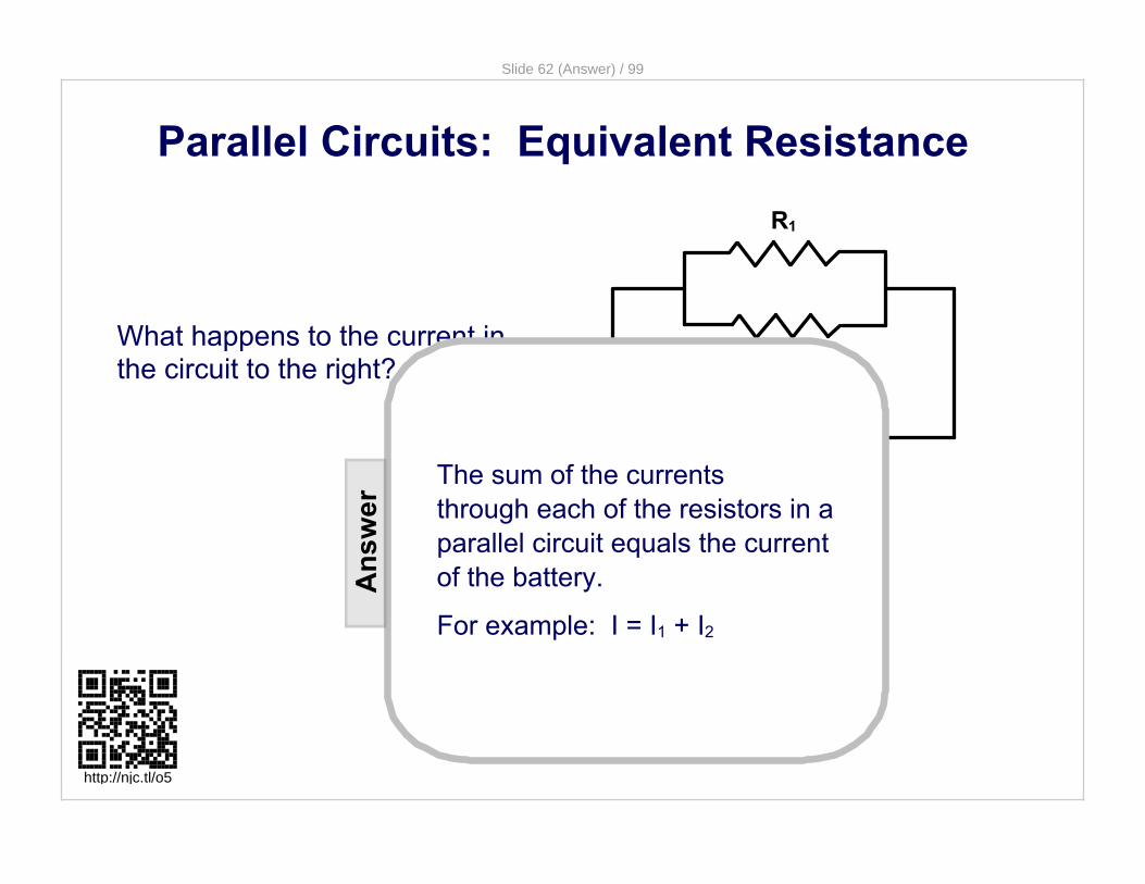
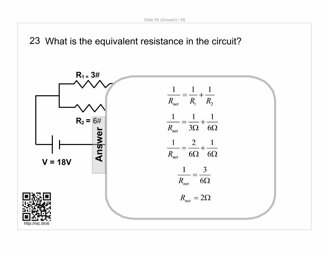
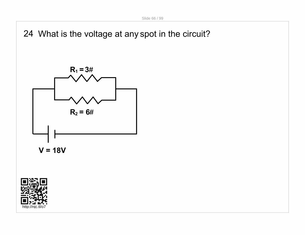
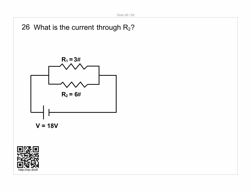
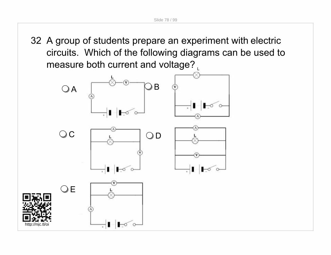
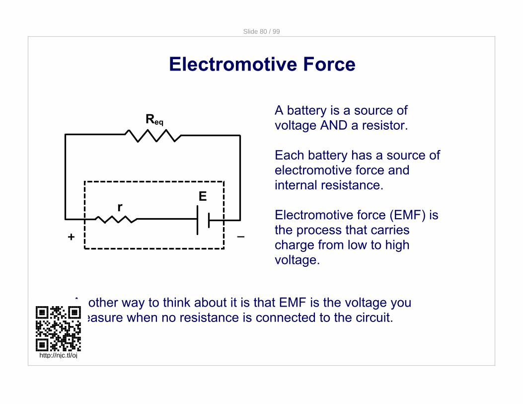
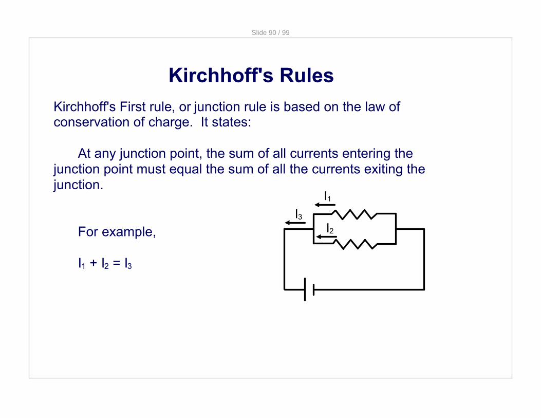
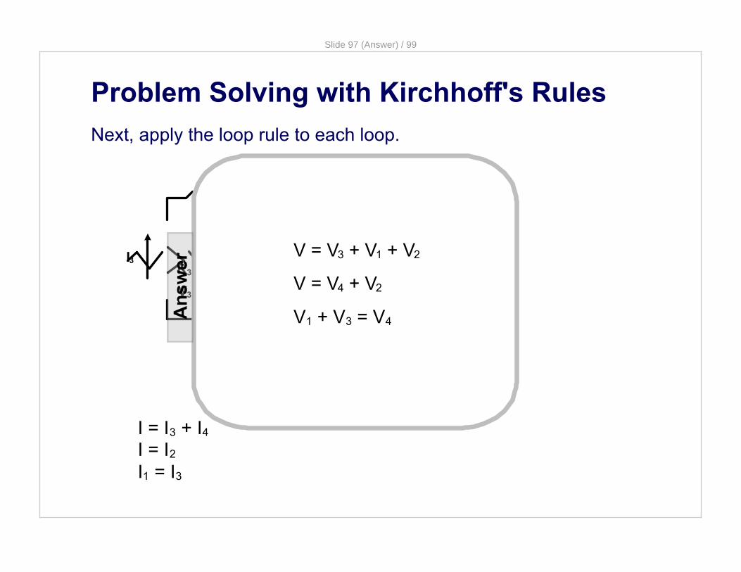
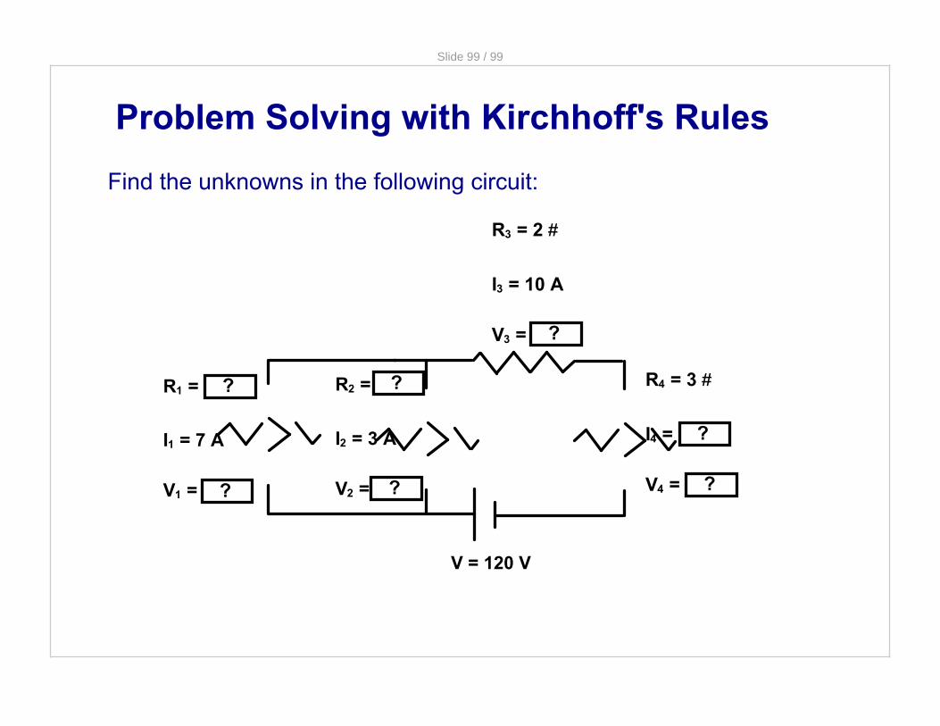
Slide 99 99
Find the unknowns in the following circuit
Problem Solving with Kirchhoffs Rules
V = 120 V
R1 = 10
I1 = 7 A
V1 = 70 V
R3 = 2
I3 = 10 A
V3 = 20 V
R4 = 3
I4 = 10 A
V4 = 30 V
R2 = 23
I2 = 3 A
V2 = 70 V