Embed Size (px)
Citation preview

1.
2.
ELECTRICAL MACHINE-1
List of contents
Introduction to Electrical Machines
1.1 Definition of motor and generator 1.2 Torque development due to alignment of two fields and the concept of torque
angle
1.3 Electro-magnetically induced emf 1.4 Elementary concept of an electrical machine
1.5 Comparison of generator and motor
DC Machines
2.1 Main constructional features, Types of armature winding 2.2 Function of the commutator for motoring and generation action
2.3 Factors determining induced emf
2.4 Factors determining the electromagnetic torque 2.5 Various types of DC generators
2.6 Significance of back e.m.f., the relation between back emf and Terminal voltage 2.7 Armature Reaction
2.8 Methods to improve commutation
2.9 Performance and characteristics of different types of DC motors 2.10 Speed control of dc shunt/series motors
2.11 Need of starter, three point dc shunt motor starter and 4 point starter 2.12 Electric Braking
2.13 Applications of DC motors 3. Single phase Transformer 4. Three Phase transformer
1 | P a g e

1Introduction to Electrical Machines
Electric machine is a general term for machines using electromagnetic forces, such as electric
motors, electric generators, and others. They are electromechanical energy converters: an electric
motor converts electricity to mechanical power while an electric generator converts mechanical
power to electricity. The moving parts in a machine can be rotating (rotating machines) or linear
(linear machines)
1.1Definition of motor and generator
A motor is a device which converts electrical energy to mechanical energy (or motion)
A generator is a device which converts mechanical energy into electrical energy.
1.2 Torque development
The tangential electromagnetic („BIl‟) force on all the positive conductors will be to the left, while the force on the negative ones will be to the right. A nett couple, or torque will therefore be exerted on the rotor, which will be caused to rotate.
1.3 Electro-magnetically induced emf
When a conductor cuts through lines of magnetic flux or when the magnetic flux field changes in
strength around a conductor, an emf is generated (induced) in the conductor. This emf is called
an induced emf. If the conductor forms part of a circuit, as in the above cases where it is
connected to a galvanometer, that emf produces a current. The current is called an induced
current. The phenomenon we are talking about is called electromagnetic induction
This change in flux can be obtained in two different ways; that is by staticallyor
by dynamically induced emf
Static induced EMF
This type of EMF is generated by keeping the coil and the magnetic field system, both of them
stationary at the same time; that means the change in flux linking with the coil takes place without either moving the conductor (coil) or the field system.
This change of flux produced by the field system linking with the coil is obtained by changing the electric current in the field system.
It is further divided in two ways
Self-induced emf (emf which is induced in the coil due to the change of flux produced by it linking with its own turns.)
2 | P a g e

Mutually induced emf (emf which is induced in the coil due to the change of flux produced by another coil, linking with it.)Dynamic induced EMFIn dynamically induced emf the magnetic field system is kept stationary, and the conductor ismoving, or the magnetic field system is moving, and the conductor is stationary thus by following either of the two process the conductor cuts across the magnetic field and the emf is induced in the coil.This phenomenon takes place in electric generators and back emf of motors and also in transformers.
1.4 Elementary concept of an electrical machine
Fleming’s left hand rule
It is used to determine the direction of force acting on a current carrying conductor placed in amagnetic field. The middle finger, the fore finger and thumb of the left hand are kept at right angles to one another.The middle finger represents the direction of currentThe fore fingers represent the direction of magnetic field. The thumb will indicate the direction of force acting on the conductor. This rule is used in motors
Fleming’s Right hand rule Used to determine the direction of emf induced in a conductor The middle finger, the fore finger and thumb of the left hand are kept at right angles to one
another. The fore finger represents the direction of magnetic field .The thumb represent the direction of motion of the conductor. The middle finger will indicate the direction of the inducted emf .This rule is used in DC Generators
Fig. Fleming right hand rule
3 | P a g e

1.5 Comparison between of Motor and Generator
Motor
• Motor converts electrical energy into mechanical energy. • DC motor uses Fleming left hand rule. • Efficiency of motor is ratio of mechanical power to Electrical power
Generator
• A generator converts mechanical energy into electrical energy • Generator uses Fleming right hand rule. • Efficiency of generator is ratio of Electrical power to mechanical power
Short Answer type Question Q1 Define Motor
Q2 Define Generator. Q3 Write the name of working principle used for motor and generator.
Long Answer type Questions Q1 Compare motor and generator.
Q2 Explain Electro-magnetically induced emf. Q3 Explain Fleming right and left hand rule.
4 | P a g e

DC Machines
2.1 Main constructional features DC generator can be used as a DC motor without any constructional changes and vice versa is
also possible. Thus, a DC generator or a DC motor can be broadly termed as a DC machine The above figure shows constructional details of a simple 4-pole DC machine. A DC
machine consists of two basic parts; stator and rotor. Basic constructional parts of a DC machine are described below.
1. Yoke: The outer frame of a dc machine is called as yoke. It is made up of cast iron or steel. It not only provides mechanical strength to the whole assembly but also carries the magnetic flux produced by the field winding.
2. Poles and pole shoes: Poles are joined to the yoke with the help of bolts or welding. They
carry field winding and pole shoes are fastened to them. Pole shoes serve two purposes; (i) they support field coils and (ii) spread out the flux in air gap uniformly.
3. Field winding: They are usually made of copper. Field coils are former wound and placed
on each pole and are connected in series. They are wound in such a way that, when energized, they form alternate North and South poles
4. Armature core: Armature core is the rotor of a dc machine. It is cylindrical in shape with slots to carry armature winding. The armature is built up of thin laminated circular steel disks for reducing eddy current losses. It may be provided with air ducts for the axial air flow for cooling purposes. Armature is keyed to the shaft.
5. Armature winding: It is usually a former wound copper coil which rests in armature
slots. The armature conductors are insulated from each other and also from the armature core. Armature winding can be wound by one of the two methods; lap winding or wave winding. Double layer lap or wave windings are generally used. A double layer winding means that each armature slot will carry two different coils.
6. Commutator and brushes: Physical connection to the armature winding is made
through a commutator-brush arrangement. The function of a commutator, in a dc generator, is to collect the current generated in armature conductors. Whereas, in case of
5 | P a g e

a dc motor, commutator helps in providing current to the armature conductors. A
commutator consists of a set of copper segments which are insulated from each other. The
number of segments is equal to the number of armature coils. Each segment is connected
to an armature coil and the commutator is keyed to the shaft. Brushes are usually made
from carbon or graphite. They rest on commutator segments and slide on the segments
when the commutator rotates keeping the physical contact to collect or supply the current.
2.2 Function of the commutator for motoring and generation action The functions of the commutator are to facilitate collection of current from the armature
conductors, and to convert the alternating current induced in the armature conductors into unidirectional current in the external load circuit. In case of motor it convert dc into ac and in case of motor it convert ac into dc so it can work as rectifier and inverter both.
2.3 EMF equation • Let, • Ø= flux per pole in weber • Z = Total number of conductor • P = Number of poles • A = Number of parallel paths • N =armature speed in rpm • Eg = emf generated in any on of the parallel path • Average emf generated per conductor is given by dΦ/dt (Volts) • Flux cut by one conductor in one revolution = dΦ = PΦ ….(Weber), • Number of revolutions per second (speed in RPS) = N/60 • Therefore, time for one revolution = dt = 60/N (Seconds) • emf generated per conductor = dΦ/dt = PΦN/60 (Volts)
Eg = PφNZ/60A
2.4 Torque Equation of A DC Motor
When armature conductors of a DC motor carry current in the presence of stator field flux, a
mechanical torque is developed between the armature and the stator. Torque is given by the product of the force and the radius at which this force acts.
Torque T = F × r (N-m) …where, F = force and r = radius of the armature
Work done by this force in once revolution = Force × distance = F × 2πr (where, 2πr =
circumference of the armature)
Net power developed in the armature = word done / time
= (force × circumference × no. of revolutions) / time
= (F × 2πr × N) / 60 (Joules per second) .... eq. 2.1 But, F × r = T and 2πN/60 = angular velocity ω in radians per second. Putting these in the above
equation 2.1 Net power developed in the armature = P = T × ω (Joules per second) Armature
Torque (Ta)
The power developed in the armature can be given as, Pa = Ta × ω = Ta × 2πN/60
6 | P a g e

The mechanical power developed in the armature is converted from the electrical power, Therefore, mechanical power = electrical power
That means, Ta × 2πN/60 = Eb.Ia We know, Eb = PΦNZ / 60A
Therefore, Ta × 2πN/60 = (PΦNZ / 60A) × Ia Rearranging the above equation,
Ta = (PZ / 2πA) × Φ.Ia (N-m) The term (PZ / 2πA) is practically constant for a DC machine. Thus, armature torque is directly proportional to the product of the flux and the armature current i.e. Ta ∝ Φ.Ia
2.5 Types of DC generators:- DC generators are classified based on their method of excitation
1. Separately excited DC generator 2. Self-excited DC generator Self-excited DC generator can again be classified as
1) DC Series generator 2) DC Shunt generator and 3) DC Compound generator.
2.6 The significance of Back EMF
The presence of back emf makes the d.c. motor a self-regulating machine i.e., it makes the motor to draw as much armature current as is just sufficient to develop the torque
required by the load.
Armature current (Ia),
When the motor is running on no load, small torque is required to overcome the friction and
windage losses. Therefore, the armature current Ia is small and the back emf is nearly equal to the applied voltage.
7 | P a g e

If the motor is suddenly loaded, the first effect is to cause the armature to slow down. Therefore, the speed at which the armature conductors move through the field is reduced
and hence the back emf Eb falls. The decreased back emf allows a larger current to flow through the armature and larger current means increased driving torque. Thus, the driving torque increases as the motor slows down. The motor will stop slowing down when the armature current is just sufficient to produce the increased torque required by the load. If the load on the motor is decreased, the driving torque is momentarily in excess of the
requirement so that armature is accelerated. As the armature speed increases, the back emf Eb
also increases and causes the armature current Ia to decrease. The motor will stop accelerating
when the armature current is just sufficient to produce the reduced torque required by the load. Therefore, the back emf in a DC motor regulates the flow of armature current
i.e., it automatically changes the armature current to meet the load requirement
2.7 Armature Reaction
Armature flux superimposes with the main field flux and, hence, disturbs the main field flux (as shown in third figure the of above image). This effect is called as armature reaction in DC machines. Perpendicular to the lines of force between the two opposite adjacent poles. Leading pole Tip (LPT) : It is the end of the pole which first comes in contact with
the armature. Trailing pole tip: It is the end of the pole which comes in contact later with the armature
Effects of Armature Reaction
• It decreases the efficiency of the machine. • It produces sparking at the brushes. • It produces a demagnetizing effect on the main poles. • It reduces the emf induced. • Self-excited generators sometimes fail to build up emf.
2.8 Commutation Reversal of current in the armature coil by means of brushes and commutator segments is callded
commutation.
8 | P a g e

Methods of Improving Commutation
There are three methods of • sparkles commutation: • Resistance Commutation • Voltage Commutation • Compensating Winding
DC Motors Converts Electrical energy into Mechanical energy, Construction : Same for Generator and motor, Working principle : Whenever a current carrying conductor is placed in the
magnetic field , a force is set up on the conductor, Back Emf the induced emf in the rotating
armature conductors always acts in the opposite direction of the supply voltage, According to the
Lenz‟s law, the direction of the induced emf is always so as to oppose the cause producing it.
2.9 Characteristic of DC motors The turning or twisting force about an axis is called torque.
• P = T * 2 πN/ 60 , Eb Ia = Ta * 2 πN/ 60 • T ∞ φ I a ,Ta ∞ I2a
• T/ Ia characteristic as Ta ∝ ɸ.Ia
• N/ I a characteristic as N ∝ Eb/ɸ
• N/T characteristic from above relation
2.10 Speed control of DC motors
• According to the speed equation of a dc motor
∞ V- Ia Ra/ φ Thus speed can be controlled by- • Flux control method: By Changing the flux by controlling the current through the field
winding. • Armature control method: By Changing the armature resistance which in turn changes the
voltage applied across the armature
9 | P a g e
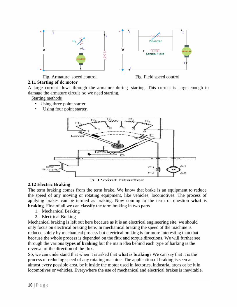
Fig. Armature speed control Fig. Field speed control
2.11 Starting of dc motor
A large current flows through the armature during starting. This current is large enough to
damage the armature circuit so we need starting.
Starting methods
• Using three point starter
• Using four point starter.
2.12 Electric Braking The term braking comes from the term brake. We know that brake is an equipment to reduce the speed of any moving or rotating equipment, like vehicles, locomotives. The process of applying brakes can be termed as braking. Now coming to the term or question what is
braking. First of all we can classify the term braking in two parts
1. Mechanical Braking 2. Electrical Braking
Mechanical braking is left out here because as it is an electrical engineering site, we should
only focus on electrical braking here. In mechanical braking the speed of the machine is
reduced solely by mechanical process but electrical braking is far more interesting than that
because the whole process is depended on the flux and torque directions. We will further see
through the various types of braking but the main idea behind each type of barking is the
reversal of the direction of the flux. So, we can understand that when it is asked that what is braking? We can say that it is the process of reducing speed of any rotating machine. The application of braking is seen at almost every possible area, be it inside the motor used in factories, industrial areas or be it in locomotives or vehicles. Everywhere the use of mechanical and electrical brakes is inevitable.
10 | P a g e

Types of Braking
Brakes are used to reduce or cease the speed of motors. We know that there are various types of
motors available (DC motors, induction motors, synchronous motors, single phase motors etc.)
and the specialty and properties of these motors are different from each other, hence this
braking methods also differs from each other. But we can divide braking in to three parts
mainly, which are applicable for almost every type of motors. 1. Regenerative Braking. 2. Plugging type braking. 3. Dynamic braking.
Applications of DC motor
Shunt DC motors are used in constant speed applications like drilling machine, lathe ,textile
machines etc.
Series motor is used in traction applications where the Load requires high starting
torque applications like cranes, hoists, elevators etc.
Multiple choice questions
Q1. Laminations of core are generally made of
(a) case iron (b) carbon (c) silicon steel(d) stainless steel Ans: c
Q2.Which of the following could be lamina-proximately the thickness of laminations of a D.C.
machine ?
(a) 0.005 mm (b) 0.05 mm (c) 0.5 m (d) 5 m Ans: c
Q4. The field coils of D.C. generator are usually made of
(a) mica(b) copper(c) cast iron (d) carbon Ans: b
Q5. The commutator segments are connected to the armature conductors by means of (a) copper lugs (b) resistance wires (c) insulation pads (d) brazing Ans: a Q6. In a commutator (a) copper is harder than mica (b) mica and copper are equally hard(c) mica is harder than copper
(d) none of the above Ans: c Q8. In D.C. generators the pole shoes are fastened to the pole core by (a) rivets (b) counter sunk screws (c) brazing (d) welding Ans: b
Short Answer type questions Q1 Define commutation and armature reaction
Q2 what is the significance of back emf?
Q3 Why we need starting of dc motor? Q4 Give types of dc generators
Q5 Draw diagram of three point starter Long Answer types Questions
Q1 Draw and explain Starting and speed control methods of dc motor.
Q2 Draw various types of characteristic of dc motor
11 | P a g e

3 Single-phase transformer
Electrical power transformer is a static device which transforms electrical energy from one
circuit to another without any direct electrical connection and with the help of mutual
induction between two windings. It transforms power from one circuit to another without
changing its frequency but may be in different voltage level.
A single-phase transformer is a type of power transformer that utilizes single-phase alternating
current, meaning the transformer relies on a voltage cycle that operates in a unified time phase.
It consists of two coils of electrical wire called inner and outer windings. The primary is usually
known to have the higher amount of voltage. Both coils are wrapped around a common closed
magnetic iron circuit which is referred to as the core. The core is made up of several layers of
iron, laminated together to decrease losses. Being linked at the common core allows power to be
transferred from one coil to the other without an electrical connection. When current passes
through the primary coil, a magnetic field is created which induces a voltage in the secondary
coil. Usually, the primary coil is where the high voltage comes in and then is transformed to
create a magnetic field. The job of the secondary coil is to transform the alternating magnetic
field into electric power, supplying the required voltage output.
Transformer Construction (single-phase)
Where:
VP - is the Primary Voltage
VS - is the Secondary Voltage
NP - is the Number of Primary Windings
NS - is the Number of Secondary Windings
Φ (phi) - is the Flux Linkage
Notice that the two coil windings are not electrically connected but are only linked magnetically.
A single-phase transformer can operate to either increase or decrease the voltage applied to the
primary winding. When a transformer is used to “increase” the voltage on its secondary winding
with respect to the primary, it is called a Step-up transformer. When it is used to “decrease” the
voltage on the secondary winding with respect to the primary it is called a Step-down
transformer.
However, a third condition exists in which a transformer produces the same voltage on its
secondary as is applied to its primary winding. In other words, its output is identical with respect
to voltage, current and power transferred. This type of transformer is called an “Impedance
Transformer” and is mainly used for impedance matching or the isolation of adjoining electrical
circuits.

The difference in voltage between the primary and the secondary windings is achieved by
changing the number of coil turns in the primary winding ( NP ) compared to the number of coil
turns on the secondary winding ( NS ).
As the transformer is basically a linear device, a ratio now exists between the number of turns of
the primary coil divided by the number of turns of the secondary coil. This ratio, called the ratio
of transformation, more commonly known as a transformers “turns ratio”, ( TR ). This turns ratio
value dictates the operation of the transformer and the corresponding voltage available on the
secondary winding.
It is necessary to know the ratio of the number of turns of wire on the primary winding compared
to the secondary winding. The turns ratio, which has no units, compares the two windings in
order and is written with a colon, such as 3:1 (3-to-1). This means in this example, that if there
are 3 volts on the primary winding there will be 1 volt on the secondary winding, 3 volts-to-1
volt. Then we can see that if the ratio between the number of turns changes the resulting voltages
must also change by the same ratio, and this is true.
Transformers are all about “ratios”. The ratio of the primary to the secondary, the ratio of the
input to the output, and the turns ratio of any given transformer will be the same as its voltage
ratio. In other words for a transformer: “turns ratio = voltage ratio”. The actual number of turns
of wire on any winding is generally not important, just the turns ratio and this relation
Assuming an ideal transformer and the phase angles: ΦP ≡ ΦS
Note that the order of the numbers when expressing a transformers turns ratio value is very
important as the turns ratio 3:1 expresses a very different transformer relationship and output
voltage than one in which the turns ratio is given as: 1:3.
As the magnetic flux varies sinusoidally, Φ = Φmax sinωt, then the basic relationship between
induced emf, ( E ) in a coil winding of N turns is given by: emf = turns x rate of change
Where:
ƒ - is the flux frequency in Hertz, = ω/2π
Ν - is the number of coil windings.
Φ - is the amount of flux in webers

This is known as the Transformer EMF Equation. For the primary winding emf, N will be the
number of primary turns, ( NP ) and for the secondary winding emf, N will be the number of
secondary turns, ( NS ).
Open circuit test -The connection diagram for open circuit test on transformer is shown in the
figure. A voltmeter, wattmeter, and an ammeter are connected in LV side of the transformer as
shown. The voltage at rated frequency is applied to that LV side with the help of a variac of
variable ratio auto transformer.
The HV side of the transformer is kept open. Now with the help of variac, applied voltage gets
slowly increased until the voltmeter gives reading equal to the rated voltage of the LV side. After
reaching rated LV side voltage, we record all the three instruments reading (Voltmeter, Ammeter
and Wattmeter readings).
The ammeter reading gives the no load current Ie voltmeter reading V1 can be considered equal to
the secondary induced voltage of the transformer, wattmeter reading indicates the input power
during the test. As the transformer is open circuited, there is no output, hence the input power
here consists of core losses in transformer and copper loss in transformer during no load
condition. But as said earlier, the no-load current in the transformer is quite small compared to
the full load current so, we can neglect the copper loss due to the no-load current. Hence, we can
take the wattmeter reading as equal to the core losses in the transformer.
Short circuit test on transformer The connection diagram for short circuit test on transformer is shown in the figure. A
voltmeter, wattmeter, and an ammeter are connected in HV side of the transformer as shown. The
voltage at rated frequency is applied to that HV side with the help of a variac of variable ratio
auto transformer. We short-circuit the LV side of the transformer. Now with the help of variac
applied voltage is slowly increased until the wattmeter, and an ammeter gives reading equal to
the rated current of the HV side.

Losses In Transformer
In any electrical machine, 'loss' can be defined as the difference between input power and output
power. An electrical transformer is an static device, hence mechanical losses (like windage or
friction losses) are absent in it. A transformer only consists of electrical losses (iron losses and
copper losses). Transformer losses are similar to losses in a DC machine, except that
transformers do not have mechanical losses.
Losses in transformer are explained below -
(I) Core Losses Or Iron Losses
Eddy current loss and hysteresis loss depend upon the magnetic properties of the material used
for the construction of core. Hence these losses are also known as core losses or iron losses.
Hysteresis loss in transformer: Hysteresis loss is due to reversal of magnetization in the
transformer core. This loss depends upon the volume and grade of the iron, frequency of
magnetic reversals and value of flux density. It can be given by, Steinmetz formula:
Wh= ηBmax1.6
fV (watts)
where, η = Steinmetz hysteresis constant
V = volume of the core in m3
Eddy current loss in transformer: In transformer, AC current is supplied to the primary
winding which sets up alternating magnetizing flux. When this flux links with secondary
winding, it produces induced emf in it. But some part of this flux also gets linked with other
conducting parts like steel core or iron body or the transformer, which will result in induced
emf in those parts, causing small circulating current in them. This current is called as eddy
current. Due to these eddy currents, some energy will be dissipated in the form of heat.
(Ii) Copper Loss In Transformer
Copper loss is due to ohmic resistance of the transformer windings. Copper loss for the primary
winding is I12R1 and for secondary winding is I2
2R2. Where, I1 and I2 are current in primary and
secondary winding respectively, R1 and R2 are the resistances of primary and secondary winding
respectively. It is clear that Cu loss is proportional to square of the current, and current depends
on the load. Hence copper loss in transformer varies with the load.
Efficiency of Transformer Just like any other electrical machine, efficiency of a transformer can be defined as the output
power divided by the input power. That is efficiency = output / input .
Transformers are the most highly efficient electrical devices. Most of the transformers have full
load efficiency between 95% to 98.5% . As a transformer being highly efficient, output and input
are having nearly same value, and hence it is impractical to measure the efficiency of transformer
by using output / input. A better method to find efficiency of a transformer is using, efficiency =
(input - losses) / input = 1 - (losses / input).
Condition For Maximum Efficiency
Let,
Copper loss = I12R1
Iron loss = Wi

Hence, efficiency of a transformer will be maximum when copper loss and iron losses are
equal.
That is Copper loss = Iron loss.
All Day Efficiency of Transformer
As we have seen above, ordinary or commercial efficiency of a transformer can be given as
But in some types of transformers, their performance can not be judged by this efficiency. For
example, distribution transformers have their primaries energized all the time. But, their
secondaries supply little load all no-load most of the time during day (as residential use of
electricity is observed mostly during evening till midnight).
That is, when secondaries of transformer are not supplying any load (or supplying only little
load), then only core losses of transformer are considerable and copper losses are absent (or very
little). Copper losses are considerable only when transformers are loaded. Thus, for such
transformers copper losses are relatively less important .All day efficiency of a transformer is
always less than ordinary efficiency of it.
Question 1. What Is A Transformer?
Answer : A transformer is a static device which can transfer power from one circuit to another at same
frequency.
Question 2. How Does A Transformer Work?
Answer : Transformer consists of two coils.If one coil is connected with ac voltage source then it will
produce alternating flux in the core. Most of the flux is linked with second coil hence
mutually induced emf will produce in the second coil as per faraday's law of electromagnetic
induction.
Question 3. Can Dc Be Applied To Transformers ?
Answer :
No
o Transformer works on Faraday's law of Electromagnetic Induction for which
current in coil must change. If DC is applied current will not change and
transformer will not work.
o Practically winding resistance is very small. For DC ,inductive reactance is zero
and frequency is zero. Therefore impedance is low. Thus winding draws more
current which may damage the winding.
Question4 What Are The Various Types Of Transformers?
Answer :
Based on supply o Single phase transformer
o Three phase transformer
Based on winding o Auto transformer (single winding)
o Two winding transformer
o Three winding transformer
o Six winding transformer
Based on construction o Core Type transformer
o Shell Type transformer
Based on the service o Distribution transformer

o Power transformer
Based on measurement o Current transformer
o potential transformer
Based on cooling o Dry type Transformer
o Oil immersed type transformer
Based on function o Step up transformer
o Step down transformer
o Isolation transformer
Question 5. What Is Single And Three Phase Transformer?
Answer : The transformer which works on single phase is called single phase transformer.
The transformer which works on three phase is called three phase transformer.
Question 6. What Is Auto-transformer?
Answer : In these transformer only one winding is used as primary and secondary. Also, primary and
secondary are conductively coupled.
Question 7. Why Are Iron Losses Considered As Constant Losses In Transformer?
Answer : Iron losses depend on supply frequency and flux density in the core. For all normal operations,
the frequency of flux reversals which is same as supply frequency is constant and the value of
flux density more or less remains constant. Hence iron losses remain constant under all load
conditions. i-e from no-load to full-load.
Question 8. Why Oc Test Is Generally Performed On Lv Side Of A Transformer?
Answer : The high-voltage side is generally kept open because the current in high-voltage winding is
less compared to that on low-voltage winding.The LV side has higher current so that
maximum no load current can be measured.
Question 9. Why Sc Test Is Generally Performed On Hv Side Of A Transformer?
Answer : The rated current is less on HV side. This will also permit to use ammeter and wattmeter of
lower current range.
Question 10. Why The Open Circuit Test On A Transformer Is Conducted At Rated
Voltage?
Answer : The open circuit on a transformer is conducted at a rated voltage because core loss depends
upon the voltage. This open circuit test gives only core loss or iron loss of the transformer.
Question 11. What Is Determined From Short Circuit Test?
Answer :
Copper loss.
Question 12. What Is Determined From Sumpner's Test?
Answer :
Efficiency as well as temperature rise of winding.
Question 13. What Is The Need For Parallel Operation Of Transformer?
Answer : o Non availability of single large transformer to meet the load

o Increased power demand
o To improve reliability
o If many smaller transformer is used one can be used as spare
o Transportation problem for large transformer.
Question 14. What Are The Conditions For Parallel Operation Of Transformer?
Answer : o Equal polarity
o Equal turn ratio
o percentage impedance should be same
o Equal X/R ratio
o Equal KVA rating
o Equal phase sequence.
Question15 What Is Buchholz Relay?
Answer : It protects the transformer from their internal faults like earth faults, winding short circuit,
short circuit between phases, Puncture of bushing etc.
Question 16. What Is The Humming Of Transformer?
Answer : Humming is a sound, which is produced due to the vibration of the cores in the transformer. The
vibrations are produced due to the change in polarity of an alternating current or voltage and by
the loose of lamination of the core. Both can be minimized by tightening the core of the
transformer.

Unit 4 Three Phase Transformer
Three Phase Transformer Connections
The primary and secondary windings of a transformer can be connected in different configuration
as shown to meet practically any requirement. In the case of three phase transformer windings,
three forms of connection are possible: “star” (wye), “delta” (mesh) and “interconnected-star”
(zig-zag).
The combinations of the three windings may be with the primary delta-connected and the
secondary star-connected, or star-delta, star-star or delta-delta, depending on the transformers
use. When transformers are used to provide three or more phases they are generally referred to as
a Polyphase Transformer.
Three Phase Transformer Star and Delta Configurations
But what do we mean by “star” (also known as Wye) and “delta” (also known as Mesh) when
dealing with three-phase transformer connections. A three phase transformer has three sets of
primary and secondary windings. Depending upon how these sets of windings are
interconnected, determines whether the connection is a star or delta configuration.
The three available voltages, which themselves are each displaced from the other by 120
electrical degrees, not only decided on the type of the electrical connections used on both the
primary and secondary sides, but determine the flow of the transformers currents.
With three single-phase transformers connected together, the magnetic flux‟s in the three
transformers differ in phase by 120 time-degrees. With a single the three-phase transformer there
are three magnetic flux‟s in the core differing in time-phase by 120 degrees.
The standard method for marking three phase transformer windings is to label the three primary
windings with capital (upper case) letters A, B and C, used to represent the three individual
phases of RED, YELLOW and BLUE. The secondary windings are labelled with small (lower

case) letters a, b and c. Each winding has two ends normally labelled 1 and 2so that, for example,
the second winding of the primary has ends which will be labelled B1and B2, while the third
winding of the secondary will be labelled c1 and c2 as shown.
Transformer Star and Delta Configurations
Symbols are generally used on a three phase transformer to indicate the type or types of
connections used with upper case Y for star connected, D for delta connected and Z for
interconnected star primary windings, with lower case y, d and z for their respective secondaries.
Then, Star-Star would be labelled Yy, Delta-Delta would be labelled Dd and interconnected star
to interconnected star would be Zz for the same types of connected transformers.
Transformer Winding Identification
Connection Primary Winding Secondary Winding
Delta D d
Star Y y

Interconnected Z z
We now know that there are four different ways in which three single-phase transformers may be
connected together between their primary and secondary three-phase circuits. These four
standard configurations are given as: Delta-Delta (Dd), Star-Star (Yy), Star-Delta (Yd), and
Delta-Star (Dy).
Transformers for high voltage operation with the star connections has the advantage of reducing
the voltage on an individual transformer, reducing the number of turns required and an increase
in the size of the conductors, making the coil windings easier and cheaper to insulate than delta
transformers.
The delta-delta connection nevertheless has one big advantage over the star-delta configuration,
in that if one transformer of a group of three should become faulty or disabled, the two remaining
ones will continue to deliver three-phase power with a capacity equal to approximately two thirds
of the original output from the transformer unit.
Transformer Delta and Delta Connections
In a delta connected ( Dd ) group of transformers, the line voltage, VL is equal to the supply
voltage, VL = VS. But the current in each phase winding is given as: 1/√3 × IL of the line current,
where IL is the line current.
One disadvantage of delta connected three phase transformers is that each transformer must be
wound for the full-line voltage, (in our example above 100V) and for 57.7 per cent, line current.
The greater number of turns in the winding, together with the insulation between turns,
necessitate a larger and more expensive coil than the star connection. Another disadvantage with
delta connected three phase transformers is that there is no “neutral” or common connection.
In the star-star arrangement ( Yy ), (wye-wye), each transformer has one terminal connected to a
common junction, or neutral point with the three remaining ends of the primary windings

connected to the three-phase mains supply. The number of turns in a transformer winding for star
connection is 57.7 per cent, of that required for delta connection.
The star connection requires the use of three transformers, and if any one transformer becomes
fault or disabled, the whole group might become disabled. Nevertheless, the star connected three
phase transformer is especially convenient and economical in electrical power distributing
systems, in that a fourth wire may be connected as a neutral point, ( n ) of the three star
connected secondaries as shown.
Transformer Star and Star Connections
The voltage between any line of the three-phase transformer is called the “line voltage”, VL,
while the voltage between any line and the neutral point of a star connected transformer is called
the “phase voltage”, VP. This phase voltage between the neutral point and any one of the line
connections is 1/√3 × VL of the line voltage. Then above, the primary side phase voltage, VP is
given as.
The secondary current in each phase of a star-connected group of transformers is the same as that
for the line current of the supply, then IL = IS.
Q1. What Are The Advantages Of Three Phase Transformer Over Three Single Phase
Transformer?
Answer : 1. Saving in iron material
2. Small size
3. Less transformer oil
4. Economical
5. Higher efficiency

Q2 What Is The Function Of Transformer Oil In A Transformer ?
Answer :
Transformer oil provides: 1. good insulation and
2. cooling .
Nowadays instead of natural mineral oil, synthetic oils known as ASKRELS (trade name ) are
used. They are non-inflammable, under an electric arc do not decompose to produce inflammable
gases.
Q3 What Is Conservator?
Answer : A conservator is a small cylindrical drum fitted just above the transformer main tank. It is used to
allow the expansion and contraction of oil without contact with surrounding atmosphere. When
conservator is fitted in a transformer, the tank is fully filled with oil and the conservator is half
filled with oil.
Q4 What Is Buchholz Relay?
Answer : It protects the transformer from their internal faults like earth faults, winding short circuit, short
circuit between phases, Puncture of bushing etc.
Q5 Where Is Buchholz Relay Located?
Answer :
It is located between transformer tank and conservator.
Q6 List Some Methods Of Cooling Of Transformers?
Answer : Air natural, Air blast, Oil Natural, Oil natural air forced, Oil natural water forced, Oil forced, Oil
forced air natural, Oil forced air natural, Oil forced water forced.
.


![[The, Commutator] Vol.1 Issue1](https://img.dokumen.tips/doc/110x75/568c534b1a28ab4916ba2bff/the-commutator-vol1-issue1.jpg)


![Alternating Current Commutator Motors .. (1905])](https://img.dokumen.tips/doc/110x75/577cc4bd1a28aba7119a43ff/alternating-current-commutator-motors-1905.jpg)