Embed Size (px)
Citation preview
Electric Baja
Preliminary Proposal
Shamlan Albahar
Fahad Alhowaidi
LeAlan Kinlecheenie
Andres Parra
Drew Stringer
2019-2020
Project Sponsor: W.L. Gore
Instructor: Sarah Oman
Client: David Willy

i
DISCLAIMER
This report was prepared by students as part of a university course requirement. While considerable effort
has been put into the project, it is not the work of licensed engineers and has not undergone the extensive
verification that is common in the profession. The information, data, conclusions, and content of this
report should not be relied on or utilized without thorough, independent testing and verification.
University faculty members may have been associated with this project as advisors, sponsors, or course
instructors, but as such they are not responsible for the accuracy of results or conclusions.

ii
TABLE OF CONTENTS
Contents DISCLAIMER ............................................................................................................................................... 1 TABLE OF CONTENTS ............................................................................................................................... 2 BACKGROUND ........................................................................................................................................... 1
1.1 Introduction ............................................................................................................................... 1 2 REQUIREMENTS .............................................................................................................................. 2
2.1 Customer Requirements (CRs).................................................................................................. 2 2.2 Engineering Requirements (ERs) .............................................................................................. 2 2.3 House of Quality (HoQ) ............................................................................................................ 4
3 DESIGN SPACE RESEARCH ........................................................................................................... 5 3.1 Literature Review ...................................................................................................................... 5
3.1.1 Shamlan Albahar .......................................................................................................... 5 3.1.1.1 UCSB Racing - Baja SAE [1] ........................................................................ 5 3.1.1.2 Camaro Performance Suspension [2] ............................................................ 5 3.1.1.3 CAMBER, CASTOR & TOE [3] .................................................................. 5 3.1.1.4 2010 BAJA SAE SUSPENSION Auburn University [4] .............................. 5 3.1.1.5 Design, Analysis and Fabrication of Rear Suspension System for an All-Terrain
Vehicle [5] ...................................................................................................................... 5 3.1.2 Fahad Alhowaidi .......................................................................................................... 6
3.1.2.1 Heim Joints and Rod Ends Video [6]............................................................. 6 3.1.2.2 Rod Ends, Sphericals, Rolling Element Bearings, [7] .................................. 6 3.1.2.3 Designing of All Terrain Vehicle [8] .............................................................. 6 3.1.2.4 Bearing and Heim Data Sheet [9] .................................................................. 6 3.1.2.5 Design and Analysis of Suspension in Baja ATV [10] ................................. 6
3.1.3 LeAlan Kinlecheenie ................................................................................................... 6 3.1.3.1 Suspension Geometry and Computation [11] ................................................ 6 3.1.3.2 2017 Bearcats Baja SAE – Steering System [12] .......................................... 6 3.1.3.3 Analysis of Steering Knuckle of All Terrain Vehicles (ATV) Using Finite Element
Analysis [13] .................................................................................................................. 7 3.1.3.4 Design and Optimization of a Baja SAE Vehicle [14]................................... 7 3.1.3.5 Northern Arizona University Baja SAE 2016 – Owner’s Manual [15] ......... 7
3.1.4 Andres Parra ................................................................................................................ 7 3.1.4.1 SAE INDIA [16] ............................................................................................ 7 3.1.4.2 How Cars Work [17] ...................................................................................... 7 3.1.4.3 OSHA [18] ..................................................................................................... 7 3.1.4.4 Foreign Trailing Arm video [19].................................................................... 7 3.1.4.5 Cornell University [20] .................................................................................. 8
3.1.5 Drew Stringer ............................................................................................................... 8 3.1.5.1 Engineering Inspiration – Brake Calculations [21] ....................................... 8 3.1.5.2 Selecting and Installing Brake System Components [22] ............................. 8 3.1.5.3 Disc Brake Science [23] ................................................................................ 8 3.1.5.4 Why You Should Bleed Your Brakes [24] ..................................................... 8 3.1.5.5 Brake Pad Selection [25] ............................................................................... 9
3.2 Benchmarking ........................................................................................................................... 9 3.2.1 System Level Benchmarking ....................................................................................... 9
3.2.1.1 Existing Design #1: Descriptive Title ............................................................ 9 3.2.1.2 Existing Design #2: Descriptive Title .......................................................... 10 3.2.1.3 Existing Design #3: Descriptive Title .......................................................... 10

iii
3.2.2 Subsystem Level Benchmarking ............................................................................... 10 3.2.2.1 Subsystem #1: Rear Suspension ................................................................... 11 3.2.2.1.1 Existing Design #1: Double Wish Bone .................................................................... 11
3.2.2.1.2 Existing Design #2: Trailing Arm and Leading Arm ................................................. 11
3.2.2.1.3 Existing Design #3: MacPherson Strut Suspension................................................... 11
3.2.2.2 Subsystem #2: Front Suspension ................................................................. 12 3.2.2.2.1 Existing Design #1:front suspension ......................................................................... 12
3.2.2.2.2 Existing Design #2: lower arm .................................................................................. 13
3.2.2.2.3 Existing Design #3: Heim joints ................................................................................ 13
3.2.2.3 Subsystem #3: Steering System ................................................................... 13 3.2.2.3.1 Existing Design #1: Rack and Pinion Steering .......................................................... 13
3.2.2.3.2 Existing Design #2: Hydraulic Steering .................................................................... 14
3.2.2.3.3 Existing Design #3: Electric Steering ........................................................................ 14
3.2.2.4 Subsystem #4: Braking System ................................................................... 15 3.2.2.4.1 Existing Design #1: Drum Brake ............................................................................... 15
3.2.2.4.2 Existing Design #2: Rotor and Brake Caliper ........................................................... 15
3.2.2.4.3 Existing Design #3: Master Cylinder ........................................................................ 16
3.3 Functional Decomposition ...................................................................................................... 16 3.3.1 Black Box Model ....................................................................................................... 17 3.3.2 Functional Model ....................................................................................................... 17
4 CONCEPT GENERATION ............................................................................................................... 19 4.1 Subsystem Concepts ................................................................................................................ 19
4.1.1 Subsystem #1: Rear Suspension ................................................................................ 19 4.1.1.1 Design #1: L-Trailing Arm .......................................................................... 19 4.1.1.2 Design #2: Mac Pherson Strut ..................................................................... 20 4.1.1.3 Design #3: Bottom Mounted Wishbone ...................................................... 20 4.1.1.4 Design #4: Top Mounted Wishbone ............................................................ 21 4.1.1.5 Design #5: A-Trailing Arm .......................................................................... 22
4.1.2 Subsystem #2: Front Suspension ............................................................................... 23 4.1.2.1 Design #1: A-arm ......................................................................................... 23 4.1.2.2 Design #2: MacPherson strut ....................................................................... 23 4.1.2.3 Design #3: Double front suspension ............................................................ 24 4.1.2.4 Design #4: semi trailing arm ........................................................................ 24 4.1.2.5 Design #5: Control arm ............................................................................... 25
4.1.3 Subsystem #3: Steering System ................................................................................. 26 4.1.3.1 Design #1: Fix Current Steering Knuckle Design ....................................... 26 4.1.3.2 Design #2: Design a New Steering Knuckle ............................................... 26 4.1.3.3 Design #3: Change Location of the Rack and Pinion .................................. 27 4.1.3.4 Design #4: Keep Original Location of the Rack and Pinion ....................... 28 4.1.3.5 Design #5: Replace Current Pinion Gear for a Bigger Pinion Gear ............ 28
4.1.4 Subsystem #4: Brake System..................................................................................... 29 4.1.4.1 Design #1: Disc Brake and Rotor ................................................................ 29 4.1.4.2 Design #2: Drum Brake ............................................................................... 29 4.1.4.3 Design #3: Motor Braking ........................................................................... 30 4.1.4.4 Design #4: Single Hand Brake .................................................................... 31 4.1.4.5 Design #5: Regenerative Braking ................................................................ 31

iv
5 DESIGNS SELECTED – First Semester .......................................................................................... 33 5.1 Technical Selection Criteria .................................................................................................... 33 5.2 Rationale for Design Selection ................................................................................................ 33
6 References ......................................................................................................................................... 35 7 APPENDICES ................................................................................................................................... 37
7.1 Appendix A: Decision Matrix ................................................................................................. 37 7.1.1 Rear Suspension......................................................................................................... 37 7.1.2 Front Suspension ....................................................................................................... 37 7.1.3 Steering ...................................................................................................................... 38 7.1.4 Brakes ........................................................................................................................ 38
7.2 Appendix B: Pugh Chart ......................................................................................................... 38 7.2.1 Rear Suspension......................................................................................................... 39 7.2.2 Brakes ........................................................................................................................ 40
7.3 Appendix C: Back of Envelope Calculations .......................................................................... 40 7.3.1 Rear Suspension......................................................................................................... 40 7.3.2 Front Suspension (Heim joints) ................................................................................. 41 7.3.3 Brakes ........................................................................................................................ 42

1
BACKGROUND
1.1 Introduction
With advances in technology, researchers in the field of automotive engineering continuously
seek to improve an aspect of existing designs such as efficiency or safety by incorporating new
design ideas. The aim of this project is to transform the 2015-2016 Baja Car to a full electric
model. The reengineering of the Baja Car into a full electric model is important for several
reasons. Firstly, electric off-road vehicles are quieter than diesel and petrol-based vehicles, with
reduced noise pollution. Secondly, an electric model would be cheaper to operate due to higher
energy efficiency and low maintenance costs due to less moving parts compared to the original
design. Thirdly, with the increasing concerns over climate change and global warming, there is
growing demand for automobile designs that enhance environmental sustainability. The electric
car design envisaged in this project provides an opportunity to enhance the use of renewable
energy, reduce environmental pollution from greenhouse gas emissions, and eco-friendly
materials. Improved air quality will lead to less health problems. Moreover, the project envisions
improved safety of the vehicle, with reduced risk for fires and explosions. The idea is to work
alongside EE Capstone Team, conform to the E-Baja safety rules, and compete against the 2019
Baja Car model. The project client is Professor David Willy. W. L. Gore is the financial sponsor.

2
2 REQUIREMENTS
This section provides both the customer and engineering requirements. The customer requirements are
provided from the SAE Baja India and the client of this project David Willy. The reason for using the
SAE Baja India is that it is the only SAE rules that have electrical based Baja rules.
2.1 Customer Requirements (CRs)
Table 1: Customer Requirements and Weight
Customer Needs Customer Weights
(5 Most to 1Least)
Safety 5
SAE India E-Baja Rules /
Industry Standards
5
Suspension System 5
Brake Design 5
Electric Compatible Drive Terrain 4
New Gear Box 4
Battery Mount 3
Steering 3
Fabrication 2
Cost 1
Table 1 shows our customer requirements that the team got from both the SAE Baja India and our client
David Willy. The weights are rated 5 being most and 1 being the least important. The highly weighted are
safety, following the rules, suspension system, and brake design (All weighted at 5). The least important
is cost and fabrication. That is because the team is willing to do fund raising to increase our budget of
3,000$ which was provided from W.L Gore. In addition, fabrication is rated at 2 out of 5 is because the
team is willing to do minor fabrication to the vehicle sub-systems such as steering and suspension. The
team will not do major fabrication for the vehicle frame. The suspension system, brake design, electric
compatible drive terrain, gear box, battery mount, and steering are all considered in the category of
reliable, robust, and durable design. And the team decided to brake it down to show the concentration of
each sub-system in the vehicle.
2.2 Engineering Requirements (ERs)
The engineering requirements generated according to the customer requirements. The engineering
requirements were ranked according to the relative technical importance, which was calculated is the
House of Quality excel spreadsheet. The engineering requirements are shown in the table below:

3
Table 2: Engineering Requirements
Engineering Requirements Relative
Technical
Importance
Technical Requirements Target
Safety (Factor of Safety) 1 To Be Determined
Speed (meters/seconds) 2 16.667 m/s = 60 km/h
Cost (Dollars $) 3 $3000 (May Change)
Torque (Newton-meters) 4 To Be Determined
Range of Motion (Degrees) 5 To Be Determined
Weight (Kilo grams) 6 363 Kg = 800 lb. (Restriction
used on original design of the
vehicle)
Power (Kilo watts) 7 7.5 Kw
Some technical requirements targets have been set to “To Be Determined” since the SAE Baja India rules
have not provided details regarding their restrictions. The team decided to follow our client David willy in
this issue, which is to follow industry standards. The team is doing research and will do a finite element
analysis (FEA) once all parts have been constructed in Solidworks and will run a von mises stress
analysis in cases of roll over and, rear and front collision. In addition, the team is currently working on
calculations for torque and range of motion.

4
2.3 House of Quality (HoQ)
The Figure below shows the House of Quality team has constructed. The top part of the House of Quality
compares each Engineering requirements with each other providing a brief vision on the complexity of
the procedure on applying each engineering requirement would result in. The body of the House of
Quality shows the Customer and Engineering Requirements compared to each other. The bottom part
shows the ranking of each Engineering Requirements based on the Absolute Technical Importance, which
has been calculated in the excel spreadsheet. The House of Quality gave the team a clearer vision of this
project. It made the team concentrate on the most important engineering requirements, which has been
mentioned above.as a result, the team is currently divided into sub-teams to ensure every customer weight
and engineering requirements are met.
Figure 1: House of Quality

5
3 DESIGN SPACE RESEARCH
The team will first understand the problem of the project, by talking with the client. The team will divide
these problems into subteams to generate solutions for each subsystem of the car. Each team member has
a subsystem and during the generation of solutions, they will report back to the team to evaluate the
solutions. To better understand this project and how to improve the Baja, the team did research on
important parts to designing an E Baja.
3.1 Literature Review
Each team member researched and benchmarked to find alternative designs for their subsystem
components. The team researched and examined similar subsystems, literature reviews, and web searches.
The following sections are from each team member and what each individual had researched for safety,
rear suspension, front suspension, steering system, and braking system.
3.1.1 Shamlan Albahar
Shamlan Albahar was working with Andres Parra to solve the suspension problem that the 2016 Baja
vehicle lacked. The sources below explain the best suspensions systems for baja vehicles and basic
calculations that the team will take into consideration.
3.1.1.1 UCSB Racing - Baja SAE [1]
The first source shows the process of University of California Santa Barbara students doing the 3-link
suspension similar to the vehicle #44 that is in the machine shop building 98C. This source shows how
reliably their suspension was and they have put their design into a torturing test going over large logs of
wood.
3.1.1.2 Camaro Performance Suspension [2]
The second resource explains the correct position of mounting the shocks. It also shows the angle of the
shocks and the forces that will be applied on the shocks. This resource provided calculations for shocks
loads and their angles.
3.1.1.3 CAMBER, CASTOR & TOE [3]
The third source explains the effectiveness of camber in vehicles and what types of camber should the
team use. Camber is the degree of wheels tilted to provide excellent control in sharp turns.
3.1.1.4 2010 BAJA SAE SUSPENSION Auburn University [4]
The fourth source is the Auburn University Baja team using Lotus and Solidworks FEA to analyze their
suspension system. It shows the effectiveness of these program. Also, it showed the durability and
reliability of their design, which is featured in NAU’s #44 vehicle and UCSB vehicle.
3.1.1.5 Design, Analysis and Fabrication of Rear Suspension System for an All-Terrain Vehicle [5]
The final source Also provides analysis using Lotus and Solidworks. It shows the effectiveness of using A
type trailing arm. In addition, it shows the camber analysis for their vehicle. This source agrees on the

6
source above and adding information that the 4th resource lacked which is the proper position of the
stabilizer bars mounting.
3.1.2 Fahad Alhowaidi
Fahad Alhowaidi was working on fixing the front suspension and he did his research of how can he fix
the front suspension and avoid snapping by fixing the heim joints and the bending bolts.
3.1.2.1 Heim Joints and Rod Ends Video [6]
This video helps with choosing the right heim joints for the car. Its also explains difference of heim joints
and how to choose the correct one to avoid snapping.
3.1.2.2 Rod Ends, Sphericals, Rolling Element Bearings, [7]
This source is helpful with making calculation to fix the heim joints on the fron suspension. The
calculation found on this source for checking how much load the heim joints will bear for given
dimensions. In order to check safety of heim joints, it must sustain the load applied on it.
3.1.2.3 Designing of All Terrain Vehicle [8]
In this website, it shows how suspensions are built and choosing the correct dimensions. It has some CAD
drawings examples, and also it shows some helpful calculations for materials on the front suspension.
3.1.2.4 Bearing and Heim Data Sheet [9]
In this source, there was a lot of helpful information of finding dimensions for the materials of the heim
joints. It has a lot of materials such as: rod ends, male series, and female series for rod ends. Moreover, it
shows a lot of information's of different materials. Finally, we can make a decision which one is best fit
out our front suspension.
3.1.2.5 Design and Analysis of Suspension in Baja ATV [10]
This found from the International Journal for Research in Applied Science & Engineering Technology. It
has a lot of analysis for the baja car. I will use this source to know what measurements are needed to make
my calculations for the front suspensions.
3.1.3 LeAlan Kinlecheenie
LeAlan was in charge of research on the subsystem steering for the E Baja. He needed to determine if the
steering components needed an upgrade or repair. The research presented is how to design an efficient
steering system for the E Baja and each source will benefit the team and their subsystem components as
well.
3.1.3.1 Suspension Geometry and Computation [11]
This source was recommend by the client, David Willy, for information on introduction to steering
calculations, analysis, and designs what steering is about. The source gives an indepth analysis on what
style of steerings there are and how to calculate the ideal steering for a vehicle. The book also explains
how to pair the front suspension with the steering components. It allows a better understanding of how to
design the front of the E Baja.
3.1.3.2 2017 Bearcats Baja SAE – Steering System [12]
This article explains the design of a steering system for a SAE Baja from a student perspective and
explains the information in a more understanding manner for the team. It describes the process of
designing new components when there is not manufactured parts for the final design. The source

7
interprets the calculations in a simpler from and explains which calculations are important for a SAE
Baja.
3.1.3.3 Analysis of Steering Knuckle of All Terrain Vehicles (ATV) Using Finite Element Analysis [13]
Steering knuckles are designed differently for varies vehicles and this sources gives an excellent
explaination of how the material and geometry of the knuckle is key elements in the a good steering
knuckle. The article explains the design of knuckles for a SAE Baja and how they analyze each part of the
knuckle with CAD analysis. The article explains how they upgraded their existing steering knuckle and
what calculations were needed.
3.1.3.4 Design and Optimization of a Baja SAE Vehicle [14]
The article explains camber of the wheels for the team to better understand. It goes on about designing a
full SAE Baja but the sources is being used for the steering component. The article givens information of
correlating the front suspension with the steering and how each subsystem effects the other component.
3.1.3.5 Northern Arizona University Baja SAE 2016 – Owner’s Manual [15]
This source is used to identify how to maintenance the current Baja vehicle the team is working with. The
owner’s manual helps the team understand the Baja vehicle they are working on. The team used it to
figure out the specifications of the components that are on the vehicle.
3.1.4 Andres Parra
Andres Parra was partnered with Shamlan Albahar to work on the rear suspension of the vehicle. The
researched sources below cover general knowledge, safety, technical specifications, and different types of
suspensions. Each source provides a summary that explains how the source benefits the team.
3.1.4.1 SAE INDIA [16]
This source educated readers in the rules of the SAE INDIA competition. It covers components of the
frame, brakes, different competitions, etc. It taught the team how to correctly name components of the
vehicle. This assisted in proper communication with the client who had experience in with the rules.
Furthermore, the source has worked as a datum for how the E Baja vehicle will result as it is different
from the regular Baja rules.
3.1.4.2 How Cars Work [17]
How Cars Work gave some students their initial knowledge of suspensions. It speaks of non-independent
and independent suspensions as well as double wishbone and trailing arm suspensions which are both on
the current vehicle being worked on. It gave the team a general idea of what is being worked in and what
are some of the positives and negatives of each kind.
3.1.4.3 OSHA [18]
OSHA stands for the Occupational Safety and Health Administration. It is used in multiple industries as a
standard for safety protocol. This includes subsections in PPE, Electricity and the four most common
accidents. Those are caught between, struck by, falls and electrocutions. Three of which are relevant to
the project, especially when the vehicle is in motion. The David Willy has expressed his largest costumer
need to be safety. That safety is to be implemented on all subprojects and testing. He also mentioned
OSHA being a useful resource which is why the team is using it.
3.1.4.4 Foreign Trailing Arm video [19]
This video functioned as another understanding of what a trailing arm is. The animation allowed for
clarity in the parts of the vehicle. It speaks of merits and drawbacks of what a trailing arm suspension
8
offers including simple construction and comparatively cheaper. Drawbacks include the bending of
trailing arms which has been an issue with the current vehicle being worked on.
3.1.4.5 Cornell University [20]
This essay talks about active suspension systems for Baja vehicles. An active suspension system would
allow the vehicle to run smoother and faster because it will adjust to the terrain the vehicle is racing on.
Initially, it identifies why active suspension is not used in Baja vehicles and then it proceeds to name a
few companies such as Fox and Polaris who have announced active suspensions for outdoor, recreational
vehicles. This source helped the team by widening the potential scope for suspension systems.
3.1.5 Drew Stringer
Drew was in charge of researching the different types of brakes that can be used for the car. He needed to
find out how many brake assemblies are needed for the car, the types of braking systems, and the different
components that go into an efficient braking system.
3.1.5.1 Engineering Inspiration – Brake Calculations [21]
The first source that was used by Drew was how to calculate the stopping power that was needed for the
car. This source was created by “Engineering Inspiration” [21]. On this website, it ran through all the
calculations that are needed to come up with an efficient, operating brake system. Through these
calculations, the team was able to determine how many brake assemblies are needed for the car and was
able to get a good idea for what size and number of master cylinders are needed for the car to brake
safely.
3.1.5.2 Selecting and Installing Brake System Components [22]
This source identified all the different components that are needed in a brake system. This source showed
the difference advantages of drum brakes and disc brakes. Through this source, the team learned what the
different types of brake lines can be used in a system and what is required when running brake lines.
There isn’t a substantial difference in the effectiveness of having larger brake lines over smaller ones. The
same amount of pressure is going to be applied no matter the brake lines. Since the fluid is relatively
incompressible the volume of liquid won’t affect the performance. The team is going to be using flex lines
for their design, which is the same as the original design on the vehicle. Due to the movement and
fluctuation that is needed for the car, rigid lines would not work for this design.
3.1.5.3 Disc Brake Science [23]
From this source, more detail was learned about the operation of disc brakes. A major part that was
learned from this source is the use of a proportioning valve. This valve is used to create equal pressure
given to the front brakes versus the rear brakes. This is generally used in disc brakes since they require a
larger pressure to operate to overcome the springs in the brake assembly. The team will not need to use a
proportioning valve since there is not concern of the rear brakes locking up first and they are not using
drum brakes. By using disc brakes all around the vehicle, the same pressure will be applied to both front
and rear.
3.1.5.4 Why You Should Bleed Your Brakes [24]
The source from BAP [24] showed the necessities and techniques for bleeding brakes. This included
getting water out of the lines as well as air. It talked about how water in the lines will act the same as
having air in the lines. Once the water heats up from the pressure, it will turn to water vapor and will
cause issues in the lines just like air. The problem with having air in the lines is that the brakes won’t be
as responsive. At some points, depending on the amount of air in the system, the brakes won’t even work
when the peddle is pushed. With bled lines, the brakes will be more powerful and will be more
responsive. This step in the brake installation usually comes near the end, if not last but it is one of the

9
most crucial for a successful system.
3.1.5.5 Brake Pad Selection [25]
As learned from this last source, there are several different options in selecting brake pads. Brake pads are
made out of several different materials and have different performance factors. The three types of brake
pads that can be bought are non-asbestos, ceramic, and semi-metallic [25]. Each of the brake pad types
mentioned all have different properties to them. Either one of the brake pad types would be suitable for
what kind of vehicle is being built. The non-asbestos pads are a softer material so on heavier vehicles they
don’t last as long, but they are quieter and the brake pad waste doesn’t pollute the surroundings. The
ceramic pads are excellent all around, they have excellent stopping power, disperse heat, and are very
quiet. The ceramic pad is what is used in most factory cars produced today. The last type, semi-metallic,
have great stopping power as well and are exceptional at dispersing heat. As the pads brake, they create
more dust which allows for the heat to leave the pads and rotors better. As said earlier, any of these types
would work for this project. The team will have to find out what types of pads are made for this size
vehicle.
3.2 Benchmarking
As explained in the project introduction, the team will work with the EE Capstone Team. The
benchmarking activities involved in this project include visits to the “Society of Automotive Engineers
(SAE)” International and Baja SAE design team to examine how the team plans to approach the design
problem with the original car model. The team shall also conduct online benchmarking through desktop
research to explore the current state of technology and discernable trends and gaps in knowledge. The key
areas that would benefit from the benchmarking include the need to reduce the cost of the materials and
the need to increase speed.
3.2.1 System Level Benchmarking
3.2.1.1 Existing Design #1: Descriptive Title
Figure 2 shows a low-cost design of an electric car based on the GAY/AG01 Model. This design
uses auto 1 speed, hydraulic brakes and 5000W power. Its main advantage is lower cost of $2800.
Although it uses cheap materials, if suffers one limitation – it has low speed of up to 40.39 mph.
Figure 2: Full System Benchmark 1 [26]
10
3.2.1.2 Existing Design #2: Descriptive Title
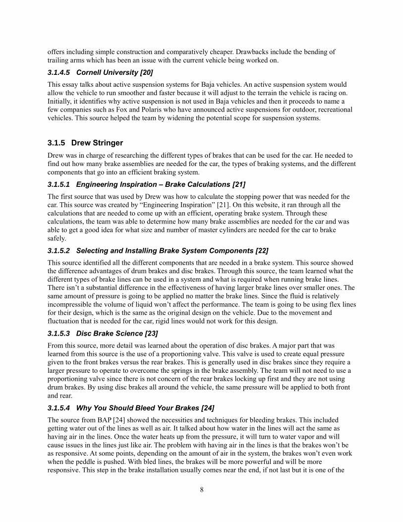
Figure 3 illustrates an electric car design that can achieve a speed of up to 60 mph. the EPIC Amp
model operates in manual 3 speed, with hydraulic brakes and 14.4 kW power. However, this design is
expensive, costing $17,900.
Figure 3: Full System Benchmark 2 [27]
3.2.1.3 Existing Design #3: Descriptive Title
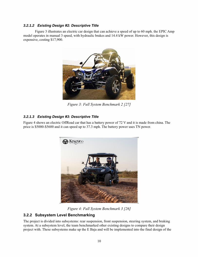
Figure 4 shows an electric OffRoad car that has a battery power of 72 V and it is made from china. The
price is $5000-$5600 and it can speed up to 37.3 mph. The battery power uses TN power.
Figure 4: Full System Benchmark 3 [26]
3.2.2 Subsystem Level Benchmarking
The project is divided into subsystems: rear suspension, front suspension, steering system, and braking
system. At a subsystem level, the team benchmarked other existing designs to compare their design
project with. These subsystems make up the E Baja and will be implemented into the final design of the
11
EBaja.
3.2.2.1 Subsystem #1: Rear Suspension
This subsystem is important for the vehicle to absorb impact and not lose integrity in the structure or
attached components. The motor and gear box are in the back which are important pieces to driving the
vehicle. The suspension system handles the terrain the vehicle is on and it improves ride quality for the
driver. Furthermore, the benchmarking done here is also what will be used for concept generation and
selection of the rear suspension. The advantages and drawbacks of each design will be discussed in the
later sections.
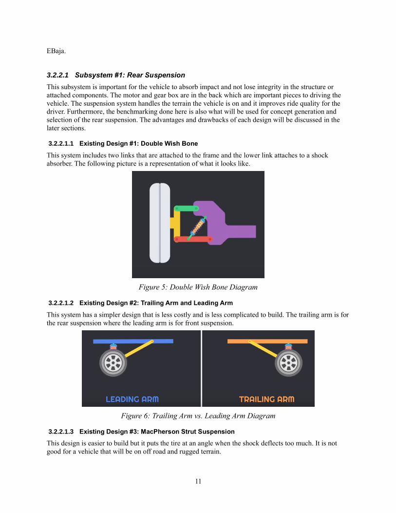
3.2.2.1.1 Existing Design #1: Double Wish Bone
This system includes two links that are attached to the frame and the lower link attaches to a shock
absorber. The following picture is a representation of what it looks like.
Figure 5: Double Wish Bone Diagram
3.2.2.1.2 Existing Design #2: Trailing Arm and Leading Arm
This system has a simpler design that is less costly and is less complicated to build. The trailing arm is for
the rear suspension where the leading arm is for front suspension.
Figure 6: Trailing Arm vs. Leading Arm Diagram
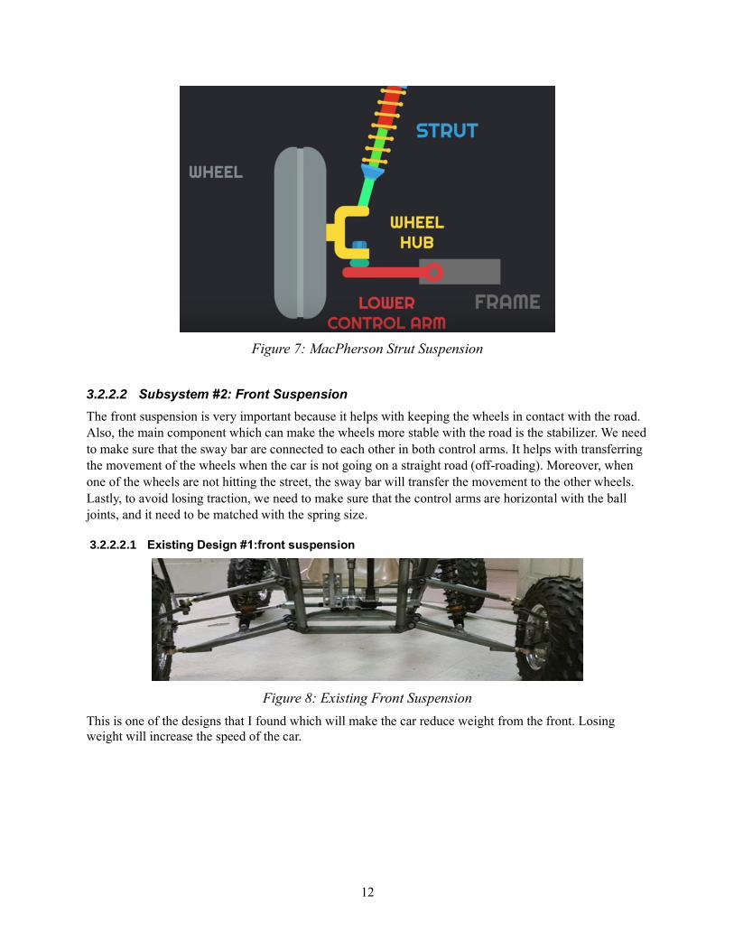
3.2.2.1.3 Existing Design #3: MacPherson Strut Suspension
This design is easier to build but it puts the tire at an angle when the shock deflects too much. It is not
good for a vehicle that will be on off road and rugged terrain.
12
Figure 7: MacPherson Strut Suspension
3.2.2.2 Subsystem #2: Front Suspension
The front suspension is very important because it helps with keeping the wheels in contact with the road.
Also, the main component which can make the wheels more stable with the road is the stabilizer. We need
to make sure that the sway bar are connected to each other in both control arms. It helps with transferring
the movement of the wheels when the car is not going on a straight road (off-roading). Moreover, when
one of the wheels are not hitting the street, the sway bar will transfer the movement to the other wheels.
Lastly, to avoid losing traction, we need to make sure that the control arms are horizontal with the ball
joints, and it need to be matched with the spring size.
3.2.2.2.1 Existing Design #1:front suspension
Figure 8: Existing Front Suspension
This is one of the designs that I found which will make the car reduce weight from the front. Losing
weight will increase the speed of the car.
13
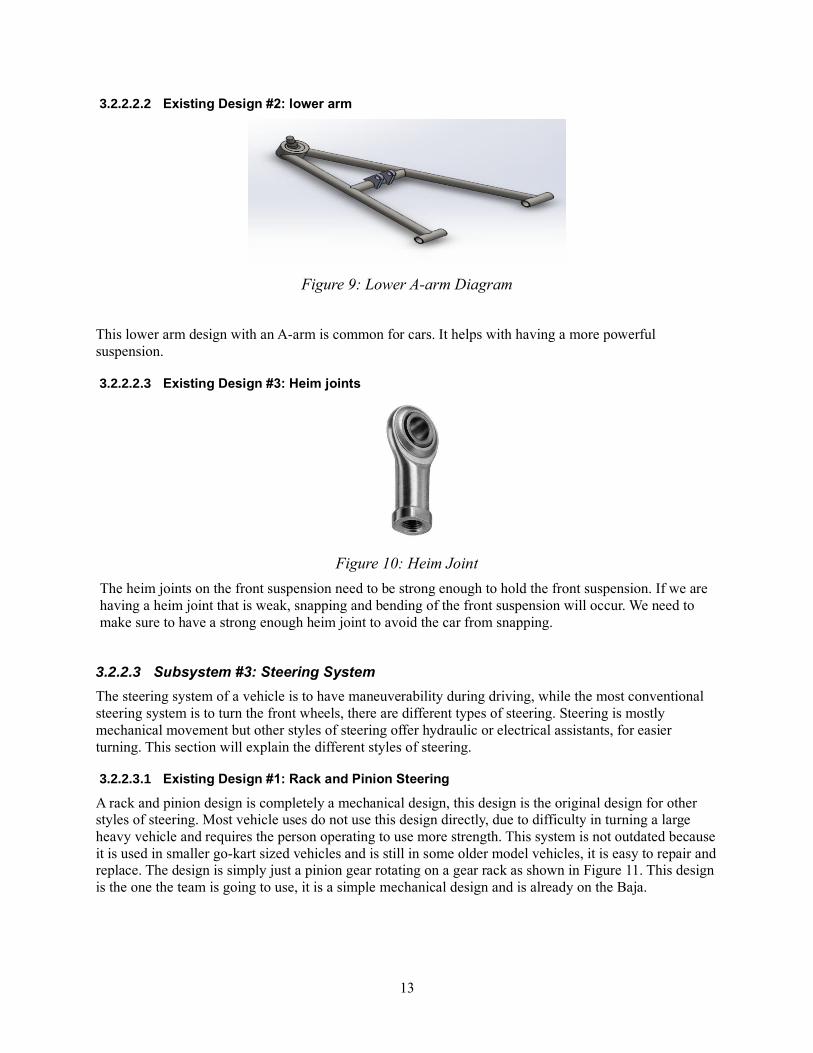
3.2.2.2.2 Existing Design #2: lower arm
Figure 9: Lower A-arm Diagram
This lower arm design with an A-arm is common for cars. It helps with having a more powerful
suspension.
3.2.2.2.3 Existing Design #3: Heim joints
Figure 10: Heim Joint
The heim joints on the front suspension need to be strong enough to hold the front suspension. If we are
having a heim joint that is weak, snapping and bending of the front suspension will occur. We need to
make sure to have a strong enough heim joint to avoid the car from snapping.
3.2.2.3 Subsystem #3: Steering System
The steering system of a vehicle is to have maneuverability during driving, while the most conventional
steering system is to turn the front wheels, there are different types of steering. Steering is mostly
mechanical movement but other styles of steering offer hydraulic or electrical assistants, for easier
turning. This section will explain the different styles of steering.
3.2.2.3.1 Existing Design #1: Rack and Pinion Steering
A rack and pinion design is completely a mechanical design, this design is the original design for other
styles of steering. Most vehicle uses do not use this design directly, due to difficulty in turning a large
heavy vehicle and requires the person operating to use more strength. This system is not outdated because
it is used in smaller go-kart sized vehicles and is still in some older model vehicles, it is easy to repair and
replace. The design is simply just a pinion gear rotating on a gear rack as shown in Figure 11. This design
is the one the team is going to use, it is a simple mechanical design and is already on the Baja.

14
Figure 11: Rack and Pinion Diagram [28]
3.2.2.3.2 Existing Design #2: Hydraulic Steering
Most current vehicles on the road today use hydraulic steering, due to it making steering a full-sized
vehicle easier. Hydraulic steering uses the rack and pinion design but adds a fluid that produces pressure
on a piston enclosed on the steering rack that allows the rack to move more efficient than just the rack and
pinion. As seen in Figure 12, moving the steering shaft allows fluid to rush to either side on the piston to
allow the steering rack to move side to side. This design would allow the team to have an easier turning
experience with the Baja but will require more maintenance and is more expensive for the team.
Figure 12: Hydraulic Steering Diagram [29]
3.2.2.3.3 Existing Design #3: Electric Steering
Vehicles that are currently being sold and produced are now being designed with electrical assistive
steering. This design still uses a rack and pinion design but consist of an electrical motor that helps rotate
the steering shaft with less rotating of the steering wheel from the driver. This design is expensive and
will not be used on the E Baja, due to limited time and limited budget. Electric steering is a useful design
for allowing the driver to turn easier, in Figure 13 shows the set up and how an electrical steering system
looks like.

15
Figure 13: Electric Power Steering Setup [30]
3.2.2.4 Subsystem #4: Braking System
For a braking system, there are multiple ways to slow down a car. For the most part, cars all brake the
same way. There are a few different designs that car manufacturers go with when designing cars. This
section will look at different braking systems on the market today.
3.2.2.4.1 Existing Design #1: Drum Brake
One existing brake design that is already out on the market is the drum brake. This brake is an expansion
braking method rather than a clamping method. When the brake is applied, two “brake shoes” are
expanded by a piston and press up against the “brake drum”. This creates the friction and force required
to stop the car. These are commonly used on the rear of vehicles but are not reasonable for our car. They
are relatively bulky and are more complicated to mount than a rotor and caliper. Figure 14 shows a
diagram of what a drum brake consists of.
Figure 14: Drum Brake Diagram [31]
3.2.2.4.2 Existing Design #2: Rotor and Brake Caliper
The most common braking system that is on cars today is the use of a rotor with a brake caliper. This uses
two brake pad that clamp onto the rotor to stop the car. This is a simple setup and doesn’t take much room
to install on a car. These are seen on the front hubs of cars and generally in the rears on newer cars as

16
well. Figure 15 shows the diagram of how a rotor and caliper is assembled. This is likely the design that
the team will use on the Baja car.
Figure 15: Rotor and Brake Disc Diagram [32]
3.2.2.4.3 Existing Design #3: Master Cylinder
One of the most important components in a brake system is the master cylinder. This is what causes the
piston to expand in either the Caliper or the Drum brake. The fluid is contained in the reservoir and is fed
into the system through different ports. The brake pedal is typically attached to the master cylinder.
Without the master cylinder, the whole brake system doesn’t work. In all cars these days, there is some
sort of master cylinder in them. The team will most definitely have one of these on the vehicle. In Figure
16, all the different parts of the master cylinder are seen.
Figure 16: Master Cylinder Diagram [33]
3.3 Functional Decomposition
This section contains a black box model that elaborates on the inputs and outputs for the vehicle to
function. To elaborate on that model, a hypothesized functional model was also created. The second
model expands on what happens within the vehicle to make it drive. The subsystems focused on were the
electrical components, the braking, and the suspension. These are some of the main components that were
directly correlated. However, there are other components such as steering that are important. Due to the
clients wishes, the team has not disassembled the vehicle which makes it difficult to see how closely
certain things are related.

17
3.3.1 Black Box Model
In this section, the Black Box Model is introduced to facilitate the visualization of this team’s project. The
purpose of the team is to create a Baja vehicle that will be capable of running on electrical power.
Therefore, this model was made based on the need for the entire vehicle to move.
Figure 17: Black Box Model
The materials used to drive the electrical Baja vehicle are batteries, a battery charger, and a driver. All of
those materials are either replaced, charged, or removed once the vehicle is no longer on. The energy used
is electrical and human which gets converted into mechanical energy via an electrical motor. The signals
provided are the on/off switch and the stop light that will tell if the vehicle is slowing down. This black
box model simplifies the problem outside of the vehicle. The inputs shown in the figure above are the
only things necessary to accomplish the team’s goal. Everything else is broken into certain subgroups
within the functional model.
3.3.2 Functional Model
This is a continuation of the black box above. It clarifies what happens within the black box. It provides a
general illustration of where the inputs go to become the outputs. However, due to client wishes, the
vehicle has not been taken apart to create a more accurate representation of internal functions.
Figure 18: Functional Model
As the black box model begins with the inputs, so does the functional model. Since most of the focus will
be on electrical components to move the vehicle, five of the subfunctions above were assigned to it. As

18
electricity moves through its components, it eventually actuates the motor to turn the shaft and become
mechanical energy in the form of rotation. However, to do that, the driver must turn on the vehicle by
using the switch that will complete the circuit. Next, the driver is able to use that mechanical energy and
control the speed by using either the throttle or the brakes. For the final subcomponent in the visual, any
dynamic movement of the vehicle will create movement in the suspension system. The suspension is used
to create stability through the dynamic movement of accelerating, braking, or the terrain the vehicle is
expected to traverse.
This functional model will help the team move forward because it gives a clearer representation of what
components affect each other. Also, there is a better understanding of why each component is important.
For example, the stop light signal is important when the brakes are being used because it warns the
subject behind it that it will stop. It keeps the driver safe which is a necessary material of the black box
model. Once the team can dissemble the vehicle, then more subcomponents will become clearer and how
they relate to one another. The three main components used in the functional model are the electrical, the
brakes and the suspension. The steering is not mentioned cause the team has not found a direct relation
yet. Although the team knows the vehicle will not drive without steering, how can it be related to the
suspension? Questions like this will be answered after disassembly.

19
4 CONCEPT GENERATION
The project will not consist of a full system design concept due to using a previous capstone’s Baja
project. In place of the full system design concept, the team will continue their research, analysis and
concept generation on subsystems for the project. Each team lead for their subsystem created concepts
and shared them with entire team to get feedback and narrow down the final design concept for the
subsystems.
4.1 Subsystem Concepts
For this project, there are multiple subsystems that the team evaluated. Due to this project having an
already set Full system design, the team did five different concepts for the subsystems. This made it so
that there were more options for designing each component. Below are the four different subsystems that
were evaluated. For the full decision matrices, they can be found in Appendix A: Decision Matrix.
4.1.1 Subsystem #1: Rear Suspension
This section contains the subconcepts spoken about in the benchmarking. It elaborates on advantages and
drawbacks of each concept. The concepts are based on the benchmark items due to the type of project.
The client wish is to fix the vehicle to move forward with the electrical portion. Therefore, the concepts
generation is based on our benchmarks.
4.1.1.1 Design #1: L-Trailing Arm
This is the original design that exists on the vehicle. It is an L-shaped trailing arm mounted on the wheel
and the frame. Also, attached in the top of it is the shocks.
Figure 19: L-Trailing Arm Diagram
Pros:
• Saves money and time if used.
Cons:

20
• Low degree of freedom.
• Unreliable and low safety.
• Low space.
4.1.1.2 Design #2: Mac Pherson Strut
This design has a single reverse A-shape type wishbone mounted on the lower part of the wheel which has
the larger length between links. The narrower part is mounted on the frame itself. The shocks are mounted
on a support on the top part of the system.
Figure 20: Mac Pherson Strut Diagram
Pros:
• Safe.
• Can support battery and motor.
Cons:
• High cost of machinery.
• Complex design (require extra fabrication).
• Provides less space.
4.1.1.3 Design #3: Bottom Mounted Wishbone
The lower wishbone is suspension system that has two identical wishbones mounted parallel to each
other. This method cancels the trailing arm from the system. The shocks here are mounted in the bottom
wishbone. This will have contact between the shocks and upper wishbone, which may result in damaging
the shocks in the long term. And adding extra cost for maintenance.

21
Figure 21: Bottom Mounted Wishbone Diagram
Pros:
• Supports battery and motor.
• Safe
Cons:
• Requires maintenance (increases cost).
• New mounts (more fabrication to the frame).
• Provides less space.
4.1.1.4 Design #4: Top Mounted Wishbone
The upper wishbone method is similar to the lower one. It also cancels the trailing arm. But the difference
is that the shocks are mounted in the top wishbone making it better in terms of less damage. The upper
type is more reliable than the bottom one.
Figure 22: Top Mounted Wishbone Diagram
22
Pros:
• Safe.
• Low cost.
• Supports battery and motor.
• Reliable.
Cons:
• New mounts (more fabrication to the frame).
• Provides less space.
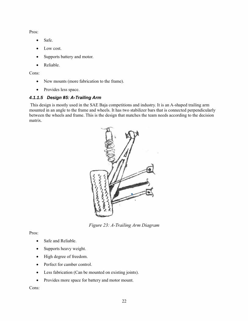
4.1.1.5 Design #5: A-Trailing Arm
This design is mostly used in the SAE Baja competitions and industry. It is an A-shaped trailing arm
mounted in an angle to the frame and wheels. It has two stabilizer bars that is connected perpendicularly
between the wheels and frame. This is the design that matches the team needs according to the decision
matrix.
Figure 23: A-Trailing Arm Diagram
Pros:
• Safe and Reliable.
• Supports heavy weight.
• High degree of freedom.
• Perfect for camber control.
• Less fabrication (Can be mounted on existing joints).
• Provides more space for battery and motor mount.
Cons:

23
• Almost expensive.
4.1.2 Subsystem #2: Front Suspension
For this subsystem, the team has made several Ideas to which design is better for our car front suspension.
Each idea has some advantages and disadvantages. The pros and cons are discussed below.
4.1.2.1 Design #1: A-arm
Figure 24: A-arm Diagram
Pros:
• Alignment wheels
• Less weighted
• Better traction
Cons:
• Easy to break
• More expensive
4.1.2.2 Design #2: MacPherson strut
Figure 25: MacPherson Strut Diagram

24
Pros:
• Easier designing
• Less components
• Lighter weight
• Less cost
Cons:
• Less handling
• Easy to break
4.1.2.3 Design #3: Double front suspension
Figure 26: Double Front Suspension Design
Pros:
• Better stability
• Strong enough for off-road use
• Well performance
Cons:
• Expensive
• Hard for designing
4.1.2.4 Design #4: semi trailing arm

25
Figure 27: Semi Trailing Arms
Pros:
• Simple design
• Few materials
Cons:
• Easy to break
• Arms are expensive
4.1.2.5 Design #5: Control arm
Figure 28: Control Arm Diagram
Pros:
• Improve wheels travel
• Less cost
• Better quality
Cons:
• Reduce ride quality
• Cause huge suspension damage when off-roading

26
4.1.3 Subsystem #3: Steering System
There are different components to the steering system, in this section the team will discuss the different
design concepts that will change or repair the steering system. Each set up will help the team create a
more efficient steering system for the E Baja. After using a decision matrix, the team narrow down the
concepts to fixing the current steering knuckle design, keeping the original ball joints, keeping the same
pinion gear, and moving the location of the rack and pinion for optimal steering.
4.1.3.1 Design #1: Fix Current Steering Knuckle Design
The current steering knuckle has an extra attachment made by the previous team that worked on the Baja,
it has been cracked and welded back together. The current team is going to upgrade the extra attachment
for better durability and optimal turning. Figure 29 shows the current design on the steering knuckle.
Figure 29: Fix Current Steering Knuckle
Pros:
• Low cost
• Client approval
Cons:
• Requires more fabrication
4.1.3.2 Design #2: Design a New Steering Knuckle
Creating a new steering knuckle would make it more durable than the current design. It will have the
ability to be last longer than the current design. The team is still considering designing a new knuckle.
Figure 30 shows the concept design for the new steering knuckle.

27
Figure 30: New Steering Knuckle
Pros:
• Safer than current knuckle
• More durable
Cons:
• High cost
4.1.3.3 Design #3: Change Location of the Rack and Pinion
The team is still doing calculations on changing the location of the rack and pinion. The current set up is
not straight towards the knuckle heim joint. The tie rods are angled back a small distance from the rack
and pinion to the connection of the knuckle. Changing the location to have an ideal straight connection
without any angle change would make the turning more efficient. Figure 31 shows the ideal placement of
steering system for an ideal Ackemann angle.
Figure 31: Change Location of the Rack and Pinion [11]
Pros:
• Ideal Ackemann angle
• Safer turning
Cons:
• High cost
28
• Requires more fabrication
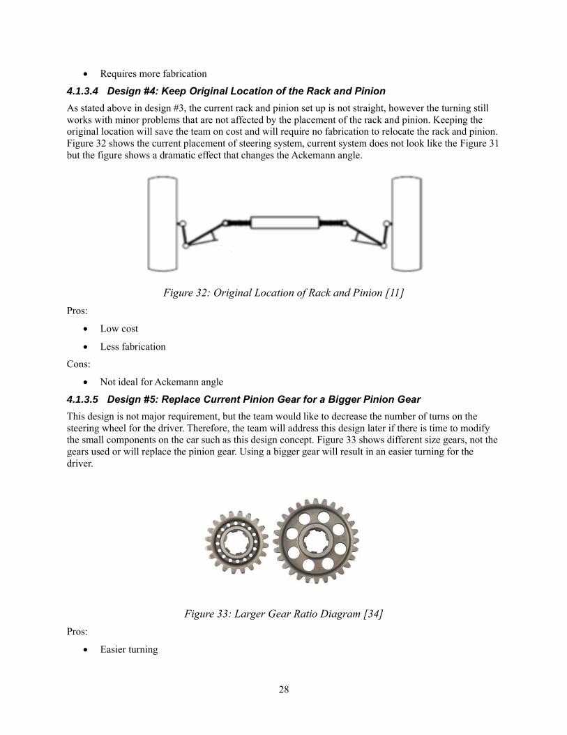
4.1.3.4 Design #4: Keep Original Location of the Rack and Pinion
As stated above in design #3, the current rack and pinion set up is not straight, however the turning still
works with minor problems that are not affected by the placement of the rack and pinion. Keeping the
original location will save the team on cost and will require no fabrication to relocate the rack and pinion.
Figure 32 shows the current placement of steering system, current system does not look like the Figure 31
but the figure shows a dramatic effect that changes the Ackemann angle.
Figure 32: Original Location of Rack and Pinion [11]
Pros:
• Low cost
• Less fabrication
Cons:
• Not ideal for Ackemann angle
4.1.3.5 Design #5: Replace Current Pinion Gear for a Bigger Pinion Gear
This design is not major requirement, but the team would like to decrease the number of turns on the
steering wheel for the driver. Therefore, the team will address this design later if there is time to modify
the small components on the car such as this design concept. Figure 33 shows different size gears, not the
gears used or will replace the pinion gear. Using a bigger gear will result in an easier turning for the
driver.
Figure 33: Larger Gear Ratio Diagram [34]
Pros:
• Easier turning

29
Cons:
• Requires more fabrication
4.1.4 Subsystem #4: Brake System
For the brake system, there were different setups and braking methods that were evaluated using a
decision matrix. After plugging the designs in the decision matrix, it was determined that the disk brake is
going to be the design that will be used on the car. It outranked the rest of the designs.
4.1.4.1 Design #1: Disc Brake and Rotor
As seen in the benchmarking, a disc brake and rotor are compact and simple way to go about stopping a
car. There isn’t a lot to it and is very common in modern cars. The brake pads are cheap and easy to get
ahold of. This design also is exceptional at stopping a car. This method doesn’t take very much pressure
in the system to clamp onto the rotor, in turn stopping the car.
Figure 34: Disc Brake [35]
Pros:
• Simple
• Stops Effectively
• Compact
Cons:
• Required on each wheel
4.1.4.2 Design #2: Drum Brake
The drum brake was also evaluated in the benchmarking process. This braking method is also super
effective. The downfall to this one is that it has a more complex setup and it requires more force to
activate the brake. Drum brakes tend to last quite a while due to having a large surface area that is
stopping the car which is nice.

30
Figure 35: Drum Brake [36]
Pros:
• Clean looking
• Last a long time
Cons:
• Heavy
• Complicated Setup
• High Force Required
4.1.4.3 Design #3: Motor Braking
Motor braking is done by having complex computer components on the car that turns the motor
backwards when braking to stop the car. When the motor applies a force opposite of the motion, the car
will come to a quick stop.
Figure 36: Motor Braking Diagram
Pros:
• Light
Cons:
• Expensive
31
• Complex computer components needed
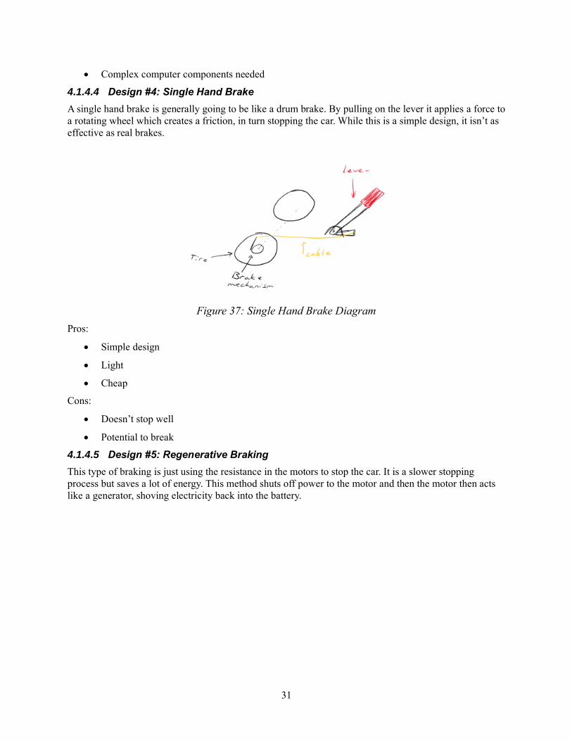
4.1.4.4 Design #4: Single Hand Brake
A single hand brake is generally going to be like a drum brake. By pulling on the lever it applies a force to
a rotating wheel which creates a friction, in turn stopping the car. While this is a simple design, it isn’t as
effective as real brakes.
Figure 37: Single Hand Brake Diagram
Pros:
• Simple design
• Light
• Cheap
Cons:
• Doesn’t stop well
• Potential to break
4.1.4.5 Design #5: Regenerative Braking
This type of braking is just using the resistance in the motors to stop the car. It is a slower stopping
process but saves a lot of energy. This method shuts off power to the motor and then the motor then acts
like a generator, shoving electricity back into the battery.

32
Figure 38: Regenerative Braking Diagram
Pros:
• Cheap
• Light
• Saves Energy
Cons:
• Way less stopping power
33
5 DESIGNS SELECTED – First Semester
This section of the report shows the final designs that the team has decided upon to build the car. It will
show the reasoning behind the decisions and how the other options ranked up. For this project, the car
frame is not supposed to have any major changes to it. Due to this, the only major changes are going to be
done to the subcomponents. The client wants the team to keep the frame the same and only adjust
mounting points and frame supports. This makes it so there are no full system concept generation ideas.
In the decision matrix there are only subcomponents. Each of the ideas that have been generated all have
to work with the original frame and comply with the SAE Baja and SAE Ebaja competition rules.
5.1 Technical Selection Criteria
The main customer needs addressed in this report consist of the car being safe, following SAE India E
Baja Rules/Standards, suspension system, brake design, steering and fabrication. To identify the
costumers, the team met with the client and he is the main customer for this project along with the team
that will drive the car. During meetings with the client, he specified these requires be fulfilled during the
first semester of the project. The team assisted a lead on each subsystem to work on each subsystem and
having other team members to assist in the designs and build. This was to break down and identify each
task the project will consist of. Each lead talked with their team partners to generate concepts that will
meet both the customer needs and engineering requirements. Some engineering requirements pertaining
to the beginning of the project designs are safety factor, speed, cost, range of motion, and weight. These
requirements helped make quantitative decisions for the design of the car.
These customer needs and engineering requirements were put into Pugh Charts to help narrow down the
design concepts that satisfied if the customer need met with the engineering requirement. This process
helped to put these design concepts into Decision Matrices for a ranking of which design concepts were
better than the others. The Decision Matrices were created for each individual subsystem for the car. Each
lead on the subsystem ranked the design concept based on the customer needs and engineering
requirements. After the rankings, the lead reported back to the other team members for team inputs on the
decisions. The Decision Matrices were used to help rank which design concept to continue working on
and improving the design.
5.2 Rationale for Design Selection
From the subsystem components that the team researched and designed, they were able to come up with
two designs that would work well for the vehicle. With the current customer needs and engineering
requirements, the team was able to come up with a final design of the car. All the designs were plugged
into decision matrices to determine which design was the best. The more important parts like the rear
suspension and the brakes were plugged into a Pugh chart as well to get the best design. These full charts
can be seen in the Appendix below.
The rear suspension design, trailing arm, was decided upon because of how sturdy it is. This design is
built like a truss with triangles and can absorb forces in several directions. This will really increase the
suspension performance and rigidity of the suspension in the rear of the car. This design outranked all the
others in the decision matrix and the Pugh chart. This design also allows for quite a bit of travel. This will
be important when the car is taken off road and goes over bumps. It will keep the car suspension from
bottoming out and possibly ruining components. It is also super simple to make this suspension stiffer or
softer depending on how heavy the rear of the car is.
The front suspension design is also going to be an improvement compared to what is on the car now. The
car in the past has had issues with the components snapping or bending. By increasing the size of the

34
supports and the diameters of the heims, the suspension will hold up much better. None of the angles or
main front suspension need to be changed due to already being a great base design. With small
improvements, this design will work great for the car. The calculations for the heim diameter can be seen
in the Appendix below.
For the steering part of the car, the biggest change that needed to be addressed was the knuckles. The ball
joints where the steering linkages and the wheels connected were breaking and needed to be redesigned to
be able to steer properly. From this need came a better and more sturdy design. While still using the same
ball joint that is on the car now, the team will just recreate a bracket to go on the knuckle to solidify the
design. Remanufacturing knuckles would cost the team a lot of time and resources so just creating new
linkages is the best idea for this part. By making the connection between the steering linkage and the
knuckle stronger, the car will steer great during testing. This is the only part that needed to be changed in
the steering section of the car. The rack and pinion all worked fine and is good enough for this design of
the car. This is not a current concern of the teams.
The brakes are the component of the car that is critical for safety. Due to this, there are several parts of the
brake system that had to be tested. In the decision matrix and Pugh chart, only the braking device itself
was compared. After these comparisons, the disk brake and rotor was the best design which is what will
be used on the car. There are actually already four disk brakes on the car already, so this will not need to
be changed. For the back of the envelope calculations, there were several calculations that were done.
Since the brakes are critical to the safety of the car, these calculations are extremely important. An Excel
sheet was created and can be seen in Appendix 7.3.4. This sheet is made to plug in different values of the
brake lever, the weight of the car, number of brake calipers, and several other factors to determine if the
setup is safe enough to stop the car. All these calculations were obtained from “Engineering Inspiration”
[21]. These calculations showed that it is needed for the team to have four brake assemblies in order to
stop the car with an acceleration of 15 ft/s2. This will allow the team to keep the brakes the same and just
get two new master cylinders.

35
6 References
[1] U. R. -. B. SAE, "UCSB Racing - Baja SAE," 31 October 2015. [Online]. Available:
http://ucsbracing.blogspot.com/. [Accessed 14 October 2019].
[2] G. Ippolito, "Camaro Performance Suspension," Camaro Tech: Performance Suspension, [Online].
Available: http://www.camarotech.com/suspension.html. [Accessed 14 October 2019].
[3] "Camber, Castor & Toe," July 2012. [Online]. Available:
http://www.gomog.com/allmorgan/CAMBER_CASTOR_TOE.html. [Accessed 14 October 2019].
[4] T. Schlereth and S. Sparks, "2010 Baja SAE Suspension," Auburn University, 2010.
[5] A. Thosar, "Design, Analysis and Fabrication of Rear Suspension System for an All Terrain
Vehicle," International Journal of Scientific & Engineering Research, vol. 5, no. 11, pp. 258-263,
2014.
[6] R. Crawler, "Youtube," 13 August 2014. [Online]. Available:
https://www.youtube.com/watch?v=ic3yWV_rlQY. [Accessed 17 October 2019].
[7] R. B. Inc., "Rod Ends, Sphericals, Rolling Element Bearings," RBC Bearings, 2012.
[8] D. Shrivastava, "Designing of All Terrain Vehicle," International Journal of Scientific and Research
Publications, vol. 4, no. 12, pp. 1-16, 2014.
[9] Bearing and Heim Data, Quality Bearings & Components.
[10] R. Kalkar, S. Chakrabarty, S. Bhandarkar, A. Singh, S. Gabhane, D. C. Handa and P. S. Bawne,
"Design and Analysis of Suspension in Baja ATV," International Journalfor Research in Applied
Science & Engineering Technology, vol. 6, no. 4, pp. 879-885, 2018.
[11] J. C. Dixon, Suspension Geometry and Computation, United Kingdom: Wiley, 2009.
[12] E. Wessels, "2017 Bearcats Baja SAE - Steering System," University of Cincinnati, Cincinnati,
2017.
[13] S. V. Dusane, M. K. Dipke and M. A. Kumbhalkar, "Analysis of Steering Knuckle of All Terrain
Vehicles Using Finite Element Analysis," IOP, 2016.
[14] A. Burgess, M. Cote, E. Crevoiserat and J. Martinez, "Design and Optimization of a Baja SAE
Vehicle," WPI, 2015.
[15] N. A. University, "Baja SAE 2016 Owner's Manual," NAU, Flagstaff, 2016.
[16] Mahindra, "Baja SAEINDIA," Majindra, 20220.
[17] H. A. C. Works, "How Car Suspension Works," [Online]. Available:
https://www.howacarworks.com/basics/how-car-suspension-works. [Accessed 17 October 2019].
[18] OSHA, "OSHA Worker Safety Series Construction," OSHA, 2018.
[19] Swing Arm Suspension: Trailing Arm, Leading Arm, Types, Working, Animation. [Film]. The
Automotives, 2018.
[20] J. Fetter, "Active Suspension for a Baja SAE Car," Cornell University, 2018.
[21] E. Inspiration, "Brake Calculations," [Online]. Available:
http://www.engineeringinspiration.co.uk/brakecalcs.html. [Accessed 17 October 2019].
[22] R. Ceridino, "Selecting And Installing Brake System Components: Proper Plumbing Pointers," Hot
Rod Network, 17 March 2017. [Online]. Available: https://www.hotrod.com/articles/selecting-
installing-brake-system-components-proper-plumbing-pointers/. [Accessed 17 October 2019].
[23] S. Rupp, "Disc Brake Science - Braking Point," Hot Rod Network, 26 October 2006. [Online].
Available: https://www.hotrod.com/articles/0601phr-braking-systems/. [Accessed 17 October 2019].
[24] B. A. Parts, "Why You Should Bleed Your Brakes," BAP, [Online]. Available:

36
https://www.buyautoparts.com/howto/the-importance-of-bleeding-brakes.html. [Accessed 17
October 2019].
[25] W. Brakes, "What are the best brake pads to buy," Wagner, [Online]. Available:
https://www.wagnerbrake.com/parts-matter/automotive-repair-and-maintenance/best-brake-pads-to-
buy.html. [Accessed 17 October 2019].
[26] "Alibaba," [Online]. Available: https://www.alibaba.com/product-detail/AGY-two-seater-go-kart-
battery_60814667941.html?spm=a2700.7724857.main07.23.35915c00SqjLBa.. [Accessed 17
October 2019].
[27] A. Morath, "In Detail: EPIC Amp Electric ATV," 13 October 2011. [Online]. Available:
https://www.autoblog.com/2011/10/13/in-detail-epic-amp-electric-atv/.. [Accessed 17 October
2019].
[28] "Rack and Pinion Design," Integrated Publishing, [Online]. Available:
http://constructionmanuals.tpub.com/14273/css/Rack-and-Pinion-312.htm. [Accessed 17 October
2019].
[29] "Rack and Pinion Steering," MOOG, [Online]. Available: https://www.moogparts.eu/blog/rack-and-
pinion-system-with-power-steering.html. [Accessed 18 October 2019].
[30] L. Motors, "Understanding the Difference Between Hydraulic & Electric Power Steering," 30
November 2017. [Online]. Available: https://medium.com/@lilydalemotorsau/understanding-the-
difference-between-hydarulic-electric-power-steering-4e3d29d01b30. [Accessed 18 October 2019].
[31] Akebono, "Drum Brakes," Akebono Brakes, [Online]. Available: https://www.akebono-
brake.com/english/product_technology/product/automotive/drum/. [Accessed 17 October 2019].
[32] C. Knight, "How to Recognize Brake Pad Wear Patterns," Your Mechanic, 25 July 2016. [Online].
Available: https://www.yourmechanic.com/article/how-to-recognize-brake-pad-wear-patterns-by-
cheryl-knight. [Accessed 17 October 2019].
[33] L. Carley, "Brake Master Cylinder," AA1Car.com, 2019. [Online]. Available:
https://www.aa1car.com/library/brake_master_cylinder.htm. [Accessed 17 October 2019].
[34] "Speedway Motors," [Online]. Available: https://www.speedwaymotors.com/BandJ-Midget-Quick-
Change-Gears,40577.html. [Accessed 18 October 2019].
[35] "Complete Guide to Disc Brakes and Drum Brakes," Lesschawab.com, [Online]. Available:
https://www.lesschwab.com/article/complete-guide-to-disc-brakes-and-drum-brakes.html.
[Accessed 17 October 2019].
[36] "Drum Brake," Visual Dictionary Online, [Online]. Available:
http://www.visualdictionaryonline.com/transport-machinery/road-transport/brakes/drum-
brake_2.php. [Accessed 17 October 2019].

37
7 APPENDICES
7.1 Appendix A: Decision Matrix
7.1.1 Rear Suspension
Table 3: Rear Suspension Decision Matrix
7.1.2 Front Suspension
Table 4: front suspension Decision Matrix

38
7.1.3 Steering
Table 4: Steering Decision Matrix
7.1.4 Brakes
Table 5: Brakes Decision Matrix
7.2 Appendix B: Pugh Chart
Rating Weighted Score Rating Weighted Score Rating Weighted Score Rating Weighted Score Rating Weighted Score
Safety 0.25 75 18.75 85 21.25 95 23.75 85 21.25 85 21.25
Low Cost 0.15 95 14.25 30 4.5 30 4.5 95 14.25 30 4.5
Support Suspension System 0.10 100 10 100 10 100 10 100 10 100 10
Durability 0.20 70 14 95 19 85 17 85 17 90 18
Less Fabrication 0.10 35 3.5 70 7 10 1 85 8.5 20 2
Client Requirement 0.20 90 18 50 10 50 10 50 10 50 10
Total (%) 1 78.5 71.75 66.25 81 65.75
1 2 4 3 5
Change Pinion Gear
Relative Ranking
WeightCriteria
Fix Knuckle New Knuckle Change Location Keep Original Location
Rating Weighted score Rating Weighted score Rating Weighted score Rating Weighted score Rating Weighted score
Safety 0.25 100 25 100 25 70 17.5 55 13.75 60 15
Cost 0.1 75 7.5 75 7.5 10 1 75 7.5 75 7.5
Stops Quickly 0.25 90 22.5 75 18.75 75 18.75 50 12.5 20 5
Less Fabrication 0.15 75 11.25 65 9.75 75 11.25 75 11.25 90 13.5
Space 0.25 75 18.75 65 16.25 90 22.5 75 18.75 90 22.5
Total (%) 1 85 77.25 71 63.75 63.5
Relative Ranking 1 2 3 4 5
Drum Brakes Motor Braking Single Hand Brake Regenerative Braking
Concept
Criteria
We
igh
t
Disc Brakes

39
7.2.1 Rear Suspension
Table 6: Rear Supsension Pugh Chart

40
7.2.2 Brakes
Table 7: Brake Pugh Chart
7.3 Appendix C: Back of Envelope Calculations
7.3.1 Rear Suspension
Figure 39: Raw Sketch on Finding the Stabilizer Bars Position for Camber Analysis
Engi
nee
rin
g
Req
uir
emen
ts
Dis
c B
rake
(D
atu
m)
Dru
m B
rake
Mo
tor
Bra
kin
g
Sin
gle
Han
d B
rake
Reg
ener
ativ
e B
raki
ng
Safety 0 S S - -
Cost 0 S - + +
Stops Quickly 0 S S - -
Less Fabrication 0 - + - +
Space 0 - + + +
Weight 0 - S + S
Sum + 0 2 3 3
Sum - 3 2 3 2
Sum S 3 3 0 1
Total 0 -3 -1 3 2

41
7.3.2 Front Suspension (Heim joints)
Figure 40: Heim Calculations

42
7.3.3 Brakes
Figure 41: Brake Calculations
http://www.engineeringinspiration.co.uk/brakecalcs.html
Cylinder Size
(in)
Bore Area
(in2)
Cylinder
Size (in)
Bore Area
(in2)
7/8 0.60 1 0.79
A (in) B (in) F (lbs)Pedal
Ratio
Pedal
Force Out
7.5 2.25 50 3.33 167
A = Distance from pivot point to middle of push/pull point
B = Distance from pivot to point of push on master cylinder
P = Pivot point
F = Force or push
# of Calipers on Cylinder 3 # of Calipers on Cylinder 0
Force from Cylinder (lbs) 277 Force from Cylinder (lbs) 92
800 Force/Caliper (lbs) 92 Force/Caliper (lbs) 92
15
12000.00
LF Brake RF Brake
Caliper D (in) 1.5 Caliper D (in) 1.5
3000 # of piston 2 # of piston 2
12.5 Net Bore Area (in^2) 3.5 Net Bore Area (in^2) 3.5
5 Braking Force 326.53 Braking Force 326.53
2.5
15000
Rear Brake
10 Caliper D (in) 1.75
8 # of piston 1
4.5 Net Bore Area (in^2) 2.4
Braking Force 222.22
0.4
2
4150
Clamp Force/wheel 1037
875
Pedal Dimesions
Front Cylinder Rear Cylinder
Front Cylinder Rear Cylinder
Force Required
Brake Torque
Braking Force/wheel (lbs)
Effective Radius
Coefficient of Friction
Radius of Tire (in)
Speed ratio btwn wheel/brake
Disc brake radius (in)
Braking Torque (Ftlbs)
Disc Outer Diameter
Disc Inner Diameter
Total Clamping Force (lbs)
Stopping Acceleration ft/s^2)
Car Weight (lbs)
Braking Force Required
Number of friction faces
Clamp Load (lbs)