Embed Size (px)
Citation preview


\


H SO ^
'/J C
^ .s25 o
p *
«
n
O

'^
ELASTICITY AND STRENGTH
OF
MATERIALS USED IN ENGINEERING CONSTRUCTION
SECTION I
BY
C. A. p. TURNER, Consulting Engineer
MINNEAPOLIS. NEW YORK, WINNIPEG.NEW ORLEANS
MEM. AM SOC. M E.
MEMBER AM SOCIETY TESTING MATERIALSMEMBER SOC. PROMOTION ENGINEERING EDUCATION
MEM, AM. SOC. C. E.
MINNEAPOUS. M1NN.« 1932
PRICE *f4)o
COPYWRIGHT. i«>i
ALL RIGHTS RESERVED

w \
•/ A^
..A
///',/ (V^
TO THE MEMORY OF THE PIONEERENGINEER MATHEMATICIAN, HENRY TURNEREDDY, THIS WORK IS DEDICATED AS ANAPPRECIATION OF THE VALUE OF HISLIFE WORK IN THE ADVANCEMENT OF THESCIENCE OF STRUCTURAL ENGINEERING.

PREFACE
Large sums are yearly wasted in providing for the suppoeed
injurious effect of moderate range of stress which really improves
metal and at the same time heavy Ices is suffered by failure to exer-
cise practical judgment in the proportion and selection of material
to resist shock in cases where the stress may at times exceed the
natural range of elasticity of the material employed.
Section I is intended to demonstrate fundamental principles
upon which rational analysis may be founded and to discuss the pro-
perties of material^ commonly used from the standpoint of the elas-
tician so that the student may apply the anah-tical methods of the
seoond section understandingly and in a scientific manner.
A development of the relations of residual to elastic strain suffi-
cient to account for elastic phenomena not understood heretofore is
here preselited for the first time and the error resulting from general
misunderstanding of these relations is discussed.
That there is but one independent modulus of elasticity for the
resistance of a homogeneous isotropic solid is here demonstrated for
the first time and the relative value of the coefficients for such a
body and their modification by residual strain are investigated.
The geometric relations of the curves of displacement and equi-
potential to the cur\'e8 of principal stress and greatest shear are set
in an exact light and the relations of these curves to the slip lines as
the yield point is pa-ssed are developed.
Finally, stress and strain are discussed from the thermo dynamic
standpoint and from the relations of the kinetic and static moduli!
the value of the potential of strain is developed in a simple manner.
Uncertainty as to stress analysis leads to waste or weakness,
frequently to both.
Section II will be devoted to the elimination of such uncertainty
for example, by the stress analysis of torsion, its part in culunm
strength and failure will be developed, and the waste and weakness
in common t}!^^ will be disclosed.
Uncertainty with reference to the relative of laws of summation,
of shear and moment bus led to waste in construction of continuous
trusses where simple trusses are stiffer and more economical, to waste
and weakness in distributioo of rivets in raihray floor beams, and to
unscientific and uneconomical types of webbing.
VI PREFACE
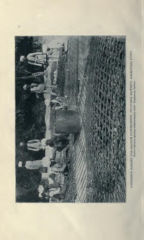
In reinforced concrete the common theory is based upon a fun-
damental misconception as to the operation of shear resulting in
diverse formulas for shear and punching shear, to account for one
and the same kind of shear strain. In formulas for plates the action
of shear stress is irrationally attributed to the tension in concrete
after the concrete is broken in tension!!
And finally the reversal of fundamental relations of states of
stress demonstrated in Natural Philosophy by Thomson and Tait,
appears in the analysis of plates by a Joint Committee Member.
C. A. P. Turner,October. 1922.

VII
CONTENTS
CHAPTER I.
Stress, Stress Resistance, Combination and Separation
1. Deformation and DLstortion. 2. Fibre Stress. •^. ^^troas,
a Deatrituded Force. 4. Resolution of Stress. 5. Moment,
Couple, Twist. 6. Axis of Maraents, Moment a Directed
Quantity. 7. External Moments. 8. Resisting Moments.
9. Equilibrium of Moments. 10. Hydraulic Stress.
11. Shearing Str^. 12. . Equilibrium Under Shear.
13. Fibre Stress Areas. 14. Moment of Inertia. 15. Maxi-
mum Fibre Stress. 16. Circle and Ellipse of Stress. 17. Pure
Stress. 18. Greatest Shear. 19. Curves of Displacement
and Hkjuipotential. 20. Combination and Separation.
21. ConserN'ation of Fibre Str«'<<s \rea.s 1-16
P.\GE
CHAPTER II.
EbcTERNAL Forces and Elastic Resistance
1. External and Internal Work. 2. Energy Defined.
3. .\nalysi.'< of Stress. 4. Elastic Limit. 5. Potential Energy
of Deformation. 6. Thermo-elastic Properties of Matter.. . 17-23
CHAPTER III.
Mechanics op Elasticity
1. Homogeneous Isotropic Bodies. 2. Kinetic or Geo-
metric Modulus. 3. Young's Modulus and Poisson's Ratio.
4. Shear Resistanc ' Stresses Acting at Right Angles.
6. D<;terminatioii .Stresses. 7. Relations Between
Elastic Constants, Kinetic and Static Modulii. 9 Summary 24-32
CHAPTER IV.
Materials op Construction
1. Properties. 2. Brick. 3. Building Stone. 4. Concrete.
5. Mo<lutus of Rupture and' Ultimate Shearing RestftMloe.
6. Timlx'r. 7. Iron and Steel. 8. Wrought Imn. 9. 8t€*l.
10. Physical Propertiee of Mild Steel. 11. Rewlling. 12.

VIII CONTENTS
Crucible Steel. 13. Electric Steel Making. 14. Gray Iron
Castings. 15. Temper. 16. Heat Treatment and Tempering.
17. Effect of Quenching Soft Steel. 18. Overstrain and Cold
Working. 19. Aeolotropic Properties of Permanent Strain. ^^
20. Summary 33-59
CHAPTER V.
Range of Imperfect Elasticity Within the Yield Point,
Endurance Tests, and Work of Rupture
1. Dissipation of Energy in Heat. 2. Elastic Afterworking.
3. Apparant Elastic Fatigue. 4. Variation in Yield Point
Values. 5. Woehler's Experiments. 6. Work of Rupture.
7. Shear Lines. 8. Factor of Safety, Maxima and MaximaFormula 60-71
CHAPTER VI.
Working Stresses Deduced
1. Stress Curves. 2. Aeolotropic Modification of Properties
by Residual Strain. 3. Thermo-elastic Relation Between
Stress and Temperature Change, an Invariant. 4. Relief
and Accumulation of Residual Strains. 5. Modification of
Volume by Residual Strain. 6. Dynamic Effects. 7. Cushion-
ing Impact. 8. Impact in Machines. 9. Working Stresses,
Steel, Stone, Brick. 10. Strength of Timber. 11. Summary. 72-85

CHAPTER I.
1. All material used in construction, no matter how rigid it mayappear when subjected to any load or applied force, suffers somechange in dimension or shape. If this change in shape is linear it
is called DEFORMATION; if angular DISTORTION. When the
deformation or distortion does not exceed a certain amount, the
material recovers its original form upon the removal of the load and
its deportment is said to be ELASTIC.The geometric relations between applied forces and the elastic
changes in shape /which they produce is studied under the title of
ELASTICITY.The proper apportionment of material to resist given loads safely
without dangerous or injurious distortion is known as the science of
STRENGTH OF MATERIAI>S.In abstract mechanics, for convenience, bodies are treated as
though perfectly rigid and forces although actually distributed are
considered as applied at material points; their direction indicated
by lines and their relative intensity or magnitude by the length of
the line laid off upon a convenient scale.
In investigation of elastic resistance, the forces to l>e considered
are the distributed elastic reactions which the internal deformation
or distortions oppose to the applieil load or forces. Accordingly
analysis of strength deals with the area of distribution of this reaction
and in particular with the determination uf the location and magni-
tude of the grc'atest intensity of the resisting forces per unit of area
which, like the weakest link in the chain, determines the strength of
the whole.
2. Fiber Stress.—As the unit change in shape (strain) and hence
its reaction (stress) may var>' in the material from point to point,
the unit of elementary area considered must l)e ver>' small. This
unit is termed a fil>er by the engineer though in mathematical theory
it is treated as an infinitenmal area; djc dy : djc dt referred to the
orthogonal axes of XYZ of the Cartesiaa 8>'8tem of coordhiates.
3. Stress in mechanics is the term used specifically to dmoteUie relative intensity of the force brought to bear upon a given fiber
or the equal and opponie reaction which the deformed fiU'r opposes
to the given applied force in maintaining equilibrium. When stated

AXIAL FORCES
in units of force per unit of area, such as pounds per square inch or
kilograms per square centimeter, it is a UNIT STRESS expressed
in the respective units of force and area adopted.
The simplest possible state of stress is that of a short pillar com-
pressed by load applied at its ends or the tension of the hanger of a
bridge floor caused by its load. The first state of stress may be
classified as simple longitudinal push or axial compression. The
second as longitudinal pull or axial tension. The total pull (P)
divided by the resisting cross section (A) equals the unit stress,
= P/A.
4. Axial Forces. Let Fig. 1 represent a flat rubber band
having a width db. Draw upon it a square abed with the diagonal
ac upon the axis of the band. Suppose the band is stretched length-
wise by the pull P. When the band is stretched
in the direction of the pull it draws in laterally
an amount dd' on one side and 66' on the other.
It is stretched longitudinally the distance cc' so
that the original square is elongated into a rhom-
bus ab'c'd'. The material has undergone angu-
lar deformation 6a6', dad', similar to that under
pure shear, as illustrated in Fig. 2, and shearing
stresses are generated in the material along planes
oblique to the axis of the direct stress.
The total axial force P which acts longitudi-
nally across any right cross section d b' of the band
acts in the same axial direction across any oblique
section making an angle v with the axis. It
exerts a total normal component on this section
of Pi=Psin V, and a tangential component P2=Pcos v. If the
area of the right cross section is A, then that of the oblique section
is A/sin v. Hence the intensity of normal component is P sin^v/A
and of the tangential component is Sa =P sin v cos v/A. The maxi-
mum value of Sg occurs when v= 45° in which case Sg = hP/A is one
half the intensity on the right section.
Any distributed force applied to a body can be resolved into
normal and tangential components at the surface to which it is
applied. When components produce normal compression they are
positive. When they produce normal tension they are negative.
Tangential components which act to produce angular rotation
in a clockwise direction are considered positive and those tending
to produce anti-clockwise rotation are negative.
Fig. 1

MOMENT—TWUT 3
Suppose the equal faces of an elementary square prism (Uxd of
an elastic body be acted upon by equal tangential forces T or T'^
flllong each of the four sides in the direction of the arrows.
These forces will distort the square into a
rhombus ab'c'd' and the total angular dis-
tortion of the area abed will be twice the angle
bob'.
As the original diagonal ac of the square
prism has been lengthened to ac' the tangential
stresses have produced tensions normal to d'b'.
Because db has been shortened to h'd' com-
Fig.2 pressions have been induced normal to ac.
^^"SSSd^^wS^^nt^ Consequently, tangential stresses produce notroTMa onM •icneat. only angular deformation but direct tensile
and compressive stress and strain as well.
5. Moment. The moment of any single force 7* (Fig. 2) about a
point 0, is the product of T by the shortest or perpendicular distance
from 7* to 0. This moment consequently depen<ls lx)th upon the
magnitude of T and the position of O with respect to T. The dis-
tance of from T is called the lever arm of T about 0.
Couple. Two parallel forces +r and —T, of equal magnitude
but of opposite sign constitute a couple, and the algebraic sum of
their moments is the same about any point whatever in their plane,
and is called the moment of the couple. Its magnitude is the pro-
duct of T by the perpendicular distance between the lines of action
of the forces of the couple. This moment may be r^arded as acting
about any point whatever of the plane or any line normal to that plane.
Twist Let any force T of a couple act parallel to the plane of
the paper along the face da of an element abed of a shaft which
extends perpendicularly to the paper, and let the other opposing
force T act along 6c, then this couple furnishes a positive twisting
moment tending to rotate the shaft in a clockwise direction. In case
the rotation of the shaft is prevented the reaction is fumishe<l by the
internal resistance of the material, equivalent to a couple JlT' acting
along the other two faces of this element abed on some element
parallel to abed situated at some distance from abed along the shaft.
By such action twisting moments are transferretl along the length of
a shaft by means of the elastic n>sistance of the mat<>rial. lliis elastic
mistanoe ocMunsts of a twisting shear on all right sections of the
shaft parallel to the face abed. Thus twist produced by moment
4 MOMENT A DIRECTED QUANTITT
transfers shear and moment along an axis of moments, in this case
along the length of the horizontal shaft transmitting power to any
desired point, and the moment remains unchanged from point to
point until a pulley is reached which reduces the moment by trans-
mitting power from the shaft to a machine.
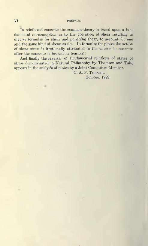
6. The Direction of the Axis of Moments may be defined as any
line drawn perpendicular to the plane containing both the force and
the lever arm. Consequently, Moment is a Directed Quantity,
acting about an axis fixed in direction. Its amount may be laid off
along that axis to represent it graphically just as a force may be laid
off along its line of action. It can only be combined with the mo-
ments of other couples by combining their axes according to the paral-
lelogram law in the same manner as forces are combined with each
other.
For example, consider the case of equal positive bending moments
acting about each of the axes of x and y that are each uniformly dis-
tributed in their action upon the respective edges
^
Fig. 3
of a unit elementary square piece of a thin plate
thus tending to bend it about both of these axes
at once. Then there is a total resultant bending
moment acting on each diagonal which is found
by multiplying that on one side by V2. But
this moment is distributed along a diagonal whose
length is V2 times one side. Hence the intensity
of the moment per unit of length is the same along the diagonal as
along a side, and it may similarly be proven that the intensity is the
same on any vertical plane whatever.
When the equal moments about x and y are of opposite sign, the
resultant moment would be of the same intensity on every plane but
would not be normal to the surface on which it acts. It would then
consist of a normal component which would be a bending moment,
and a tangential component which would be a twisting moment. Onplanes at 45" with x and y the bending moment would vanish and
the resultant moment would all be twisting.
7. External Moments. Moments of external loads and applied
forces are designated as external moments. When a load upon a
beam is multipHed by its distance from the support the moment thus
obtained is that of the load about the support and by the principle
of the lever when it is divided by the length of the beam the result
is the magnitude of the reaction at the other support due to the load
under consideration.

i
BXTKBMAI. AND BISUTINO MOMSmS ft
When the external bending mcMxients are all about one and the
same axis the resultinK curvature is cylindrical and the bent surface
is made up of parallel Htrai^^ht line elements. When the bending is
in two directions and of opposite sign a saddle shaped surface fs pro-
duce<i which is concave in one direction mid convex in another at
right an^^es to the first, and the applied moments involve twisting
and warping as weU as bending. The curvature of such a surface
is called anticlastic as opposed to tyndastic or dish shaped curva-
ture such as a surface of revolution. Dish shaped curvature is
produced by simultaneous bending in two directions when both
curvatures are of the same sign.
8. Resisting Moment The couple fonned by the resisting stresses
in the horizontal filx^rs of the material acting in tension and com-
pression in a beam' multiplied by a lever arm which is equal to the
distance between the centroids of tension and compression respect-
ively is the inlernal bending moment that opposes the external
moment producing that bending. Likewise, where the external
moment produces torsion or twist the internal moment opposing the
external moment is the interned twisting moment.
9. Equilibrium of External Moments. I. The internal i>ending
moment equals and balances the external moment of the applied
forces where the member is bent in one direction only as occurs in
cyUndrical curvature, becau.se there is no other kind of internal
m(»nent of resistance there present to produce equiUbrium.
II. Where the moment of the external applied forces produces
torsion or tinist only as in a shaft, the external moment of the
applied forces is balanced and equahni by the internal twisting mo-ment of the shear couple since thert* are no other int«'rrml momentsd resistance there present to produce oquilibrium
III. Where the member is bent in anticlastic curvature the
external moments of the applie<i forces are balanccnl {mrtly by the
internal twisting moments and partly by internal Ixuiding momentsbecause both are there present.
Deflections due to twisting or to shearing follow a fundamentally
different law from those due to lx>nding. For exiunple, when* twist-
ing momenta alone act as in a sliaft, a simpl(> summation of twisting
deformations occurs along the axis of twist without increase in stn>ss
or twisting moment, which produces relative rotations whose
amounts are equal to each other at the two ends of any portions
of the shaft that have equal lengths. Likewise in a portion of
6 RIGHT SHEARING STRESS
a beam where bending moments of the same size act at all points
there is a similar summation of shearing deformations horizontally
along the length of the beam with equal increments of shearing de-
formation at equal distances from mid span, but the deflections
follow an entirely different law.
10. Fluid or Hydraulic Stress: When an elementary cube is
subjected to normal stress of the same kind and amount in three
directions at right angles it is said to be subjected fluid or hydraulic
stress because the intensity is the same in all directions.
Plane Hydraulic Stress, or fluid stress in a plane, are the terms
applied to the condition of equal stress of the same kind in two
directions within the material on planes normal to each other.
Pass any plane whatever through the line of intersection of the
planes at right angles to each other on which there are equal normal
stresses then the stress upon such a
plane is normal thereto, and the in-
tensity thereon is the same for every
such plane as for the normal planes.
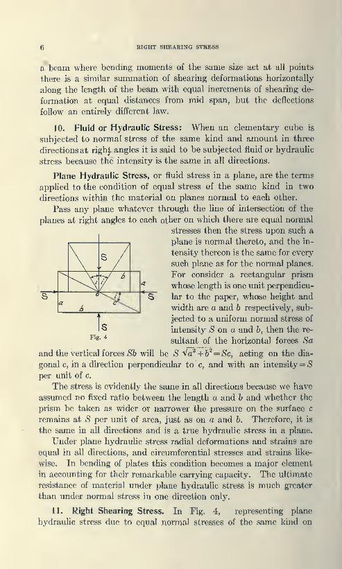
For consider a rectangular prism
whose length is one unit perpendicu-
lar to the paper, whose height and
width are a and b respectively, sub-
jected to a uniform normal stress of
intensity *S on a and h, then the re-
^'^' *sultant of the horizontal forces Sa
and the vertical forces >S6 will be S '^a^+b^=Sc, acting on the dia-
gonal c, in a direction perpendicular to c, and with an intensity= Sper unit of c.
The stress is evidently the same in all directions because we have
assumed no fixed ratio between the length a and 6 and whether the
prism be taken as wider or narrower the pressure on the surface c
remains at S per unit of area, just as on a and b. Therefore, it is
the same in all directions and is a true hydraulic stress in a plane.
Under plane hydraulic stress radial deformations and strains are
equal in all directions, and circumferential stresses and strains like-
wise. In bending of plates this condition becomes a major element
in accounting for their remarkable carrying capacity. The ultimate
resistance of material under plane hydraulic stress is much greater
than under normal stress in one direction only.
11. Right Shearing Stress. In Fig. 4, representing plane
hydraulic stress due to equal normal stresses of the same kind on
\ ^ /\ ' ' /
&* —^"^ *s
X
s

UKM AND CirUXB
jdanes at right angles to each other, suppose that one of the equal
be made of opposite sign from the other. Then one of the
components, say the horizontal component, is of opposite sign from
in hydraulic strwjs. The total resultant force, acting on the
)nal c remains unchanged in amount and inten.sity but no longer
acts normal to c, but has nomial and tangential components whose
amounts depend upon the direction of c, Ix»t c be inclined at an
angle i to the horizontal then the resultant stress makes an angle 2t
with the stress normal to c. When a = b the croes section of tlu-
prism is square so that t»45° and the plane of c makes an angle of
jf45*' with the nonnal stress, the nonnal com^wnent in c vanishes,
and the stress on l)oth diagonals is entirely tangential. This is called
a right shearing 8),ress. (N. B. Every possible state of plane stress
may be resolved into a hydraulic stress of a certain intensity super-
on a right shearing stress of suitable intensity). A state of
shearing stress at a point may therefore be defined either as
consisting of a combination of two shears of equal and opposite
intensity on planes at right angles to each other, or as a combination
of a tension and a compression of this same intensity on each of two
planes at right angles to each other making angles of +^45** with the
two shear planes first mentioned.
7. Equilibrium of an Element Under Shear. Because action
and reaction are equal and opposite every tangential shearing force
on the face of an element requires an equal and opposite shearing
force on the opposite face. Two such shearing forces produce a
rotary couple which must in some way be held in equilibrium or
balanced by distributed or concentrated forces acting on opposite
faces of the element or elsewhere. In Pure Shear the balancing
forces are equal and opposite shears on the faces at right angles to
the first pair of shears, and such distribution of stress may occur
under flexure where a change of 8lop<> n'sults from the rhomlwidal
defonnation of the square elements and in pure torsion where such
•formation occurs in the sides of the prism as before note<l. But
at those points along the length of a meml>er under flexure where
external restraint prevents rotary change in slope or horizontal
Clearing distortion, a different distribution of internal stresses is
brought about by which ecjuilibrium is maintaimnl. For example,
the supports of continudUM Im-uius built into columns are points

8 RESTRAINED SHEAR STRESS
where the tangent to the elastic curve is horizontal, and since rotary
change in slope cannot occur, the balancing distribution of tensions
and compressions at these points is brought
about by external restraint. Such distri-
bution would prevent rotation of ad about
d Fig. 5 under the opposing shears F and F,
shown in the figure. Uniformly varying
stresses like those shown in Fig. 5 due to
the rapidly varying bending moment at the
supports wiir furnish the couple required to
preserve equihbrium in this case. In fact
any couple due to normal or tangential
stresses whose moment is equal and opposite
to that of the initial shears would maintain equilibrium.
Stress distribution normal to a plane section may be repre-
sented in iatensity and direction by lines corresponding to the
direction of the fiber stress of length proportionate to their rela-
tive intensity with the sign or direction of the stress indicated byarrows
:
Fig 6ELA'iTiC JTIf£S3
Moaamow nnorriA V
they represent the relative intenBity of the streps and
it« distribution over its plane of action. The F'iber stress area for
axial stress is rectangular. For pure torsion symmetrical rectangles,
for bending at the section of ma.ximum moment, a triangle for the
compressions and a triangle for the tensions. In torsion the 8>in-
metrical filxr stress areas about the center are of hke sign. In bend-
ing they are of unlike sign, e. g., compression on the concave side and
tension on the convex side.
Characteristic deformations or distorsions of the square face of
an elementar>' prism are
—
(a) Deformation from square to rectangular takes place under
axial stress in one direction or axial stresses of unequal intensity in
two directions. The stress is uniform on opposite and adjacent faces
though of different magnitude on adjacent faces.
(6) Trapezoidal deformation occurs in bending by uniform vari-
ation in intensity of normal stress on two opposite sides of an ele-
mentary square. In the compression zone of the beam at mid span
each diagonal of the trapezoid is shortened while in the tension zone
at mid span l)oth diagonals are lengthened.
At the end of the simple beam the distortion is that of pure shear
t. e., the square face has become a rhombus in which the directions
or axes of principal strain have shifted fro»!> t)i<' ruinnal to the
diagonal of the elementary square.
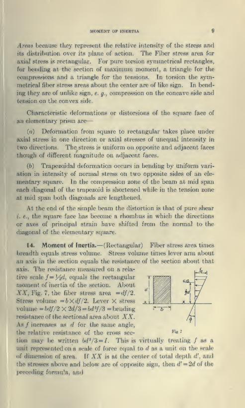
14. Moment of Inertia.—(Rectangular) Fiber stress area times
breadth cfjual.H Htro.ss volume. Stress volume times lever arm about
an axis in the section equals the resistance of the section about that
axis. The resistance measured on a rela-
tive scale /— \^, equals the rectangular
moment of inertia of the section. About
XX, Fig. 7, the filx«r stress area *df/2.
Stress volume »bXdf/2. Ijever X stress
volume - bdf/2 X 2d/3 -Wy/3 - bending
resistance of the sectional area about XX.As / increjwes as d for the same angle,
the relative resistance of the cross sec-
tion may Ik; written W/3-/. This is virtually treating / as a
unit represented on a scale of force equal to (f as a unit on the scale
of dimension of area. If XX is at the center of total depth d', and
the stresses al)ove and Inflow are of opposite sign, then d'-^Td of the
preceding formula, and
FJ«7

10 POLAR MOMENT OF INERTIA
Stress resistance =2h(^')'^f/S = bd'^f/Q, which on a relative scalrf
oif=f = bd"/S-bd'\y)' = bd'yi2 = Io
The least moment of inertia about XX is obviously that thru the
center of gravity of the section.
The moment of inertia about any parallel axis from the derivation
of / is obviously
—
r = Io-\-Ah^
in which /' is the moment of inertia desired, I o is the moment of
inertia of the area about an axis parallel to x thru its center of gravity.
A = the area (bd) and h = distance from XX to the center of gravity.
The relative resistance of the cross section is thus the sum of the
products each elementary area by the square of its distance from the
axis of rotation and is stated in mechanics in the following form
:
I = /o Joy'^ dy dx = b/^ yHy = \bd^ as before found but
its direct relation to bending resistance appears none too clearly
understood by the average student.
Polar Moment of Inertia.—J Angle *
Fig. 8 is constant; hence unit shearing
stress / is constant. Conceive the sec-
tion divided into annular rings of a
small fraction of the radius in thickness
br. The area of each ring wouldbe irr 8r
and the total shear forces tangential to its
face would be fwrdr. Since the area is
made up of all such rings between r= o
and r = R.
/T? ttR^Q irrdr = -—-
Circular Section
Fig. 6
Stress Volume = irR^f
Therefore, Stress Resistance = irR^f/2, since the lever is R.
Stress resistance on a relative scale may be written.
/=rR' = Polar Moment of Inertia.
The polar moment of inertia of a square shaft is readily obtained
from the fact that the rotational resistance must be constant thru
360°.
MAxmim riBEB arMcas 1
1
StreflB volume on short diameter ""T^ X strras volume long
diameter but the lever arm long diameter — "~7== lever for shortV 2
diameter. Hence J - b*/6, quala the sum of the rectangular
moments of inertia alwut XX and YY.
Moments of inertia for customary' shapes and form are tabulated
in all rolling mill handbooks which the student should secure.
15. Maximum Fiber Stresses, f.
(a) Pure bending equilibriunj requires M, the External Moment
= Intemal Resistance. ..M = 2bd^f'/l2 or /-6A//W« = '-p-
Placing d^2 — c, the distance of the extreme fiber from the axis, /=Mc/I the formula/or the intensity of the extreme fiber stress in bend-
ing, which is to be kept within safe working limits for the material
employed.
(6) Maximum Fiber Stress, Torsion : Ejcternal twisting momentM = Resisting Moment.
4 22 3/
*NoU:—Erroneous reasoning regarding fiber stress in torsion is
commonly found in college text books. Quoting Mcrriman's
Mechanics of Materials, 11th ed. p. 227: "Shearing unit stresses
(shown in the plane of section) var>' as their distance from the axis
of the shaft." We have shown unit shear to be constant, and present
the following proof by Rankine.
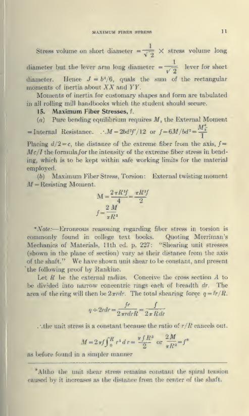
Let R \ic the external radius. Conceive the cross section A to
be divided into narrow concentric rings each of breadth dr. The
area of the ring will then l>e 2rrdr. The total shearing force q^fr/R.
.-.the unit st ress 18 a constant because the rc'v ..; , /? cancels out.
as before found in a simpler manner
*Altho the unit shear strees renuuns constant the spiral tension
caused by it increases as the distance from the center of the shaft.

12 ELLIPSE OF STRESS
16. Circle and Ellipse of Stress.—Radial representation of stress
intensity in a plane about a point furnishes a simple means of analy-
sis and resolution of stress.
When the state of stress is the same in all directions (i. e. fluid
stress) the radii of a circle described about the point at some con-
venient scale correctly represents the intensity of the stress in all
directions about the point on the relative scale adopted.
Since stress intensity is the sum of the components, tangential
(shear) or axial tension or compression along each radius the circle
may represent either equal stresses at right angles of like sign or equal
stresses at right angles of unlike sign, e. g., either a state of fluid
stress or a state of right shearing stress.
The figure representing fluid stress is a circle, and an ellipse for
the unequal stresses at right angles
Fig. 9
Starting with the circle of stress in which ox = oy, suppose ox to
gradually increase over oy. The circle gradually changes in form but
the sum total of the tangents of inclination between o and x must
remain the same.
The equation of the circle is
x^-^y^ — R^, from which the tangent is
dx y
Since the material is uniform the curve must be uniform and at
X and y the tangent must be o or oo, and hence the equation of the
curve is ax^-\-by^ = a'^b'^ i. e., an ellipse whose tangent
dx yb^
From such an ellipse the total intensity of the stress in all direc-
tions can be measured off. Its direction fixes its angle or obliquity
to any plane so that stress components tangential and normal to any
plane thru may be at once determined by the parallelogram princi-
ple.
PURE 8TRE8BBB 18
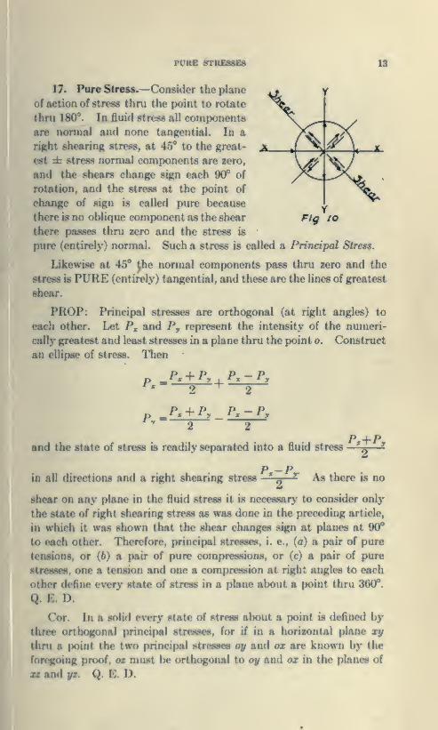
Pure Stress.—Consider the plane
of action of stress thru the point to rotate
thru 180°. In fluid stress all components
are normal and none tangential. In a
right shearing stress, at 45** to the great-
est zt stress normal components are sero,
and the shears change sign each 90° of
rotation, and the stress at the point of
change of sign is called pure because
there is no oblique component as the shear
there passes thru zero and the stress is
pure (entirely) normal. Such a stress is called a Principal Stress.
Likewise at 45° ^he normal components pass thru zero and the
stress is PURE (entirely) tangential, and these are the lines of greatest
shear.
PROP: Principal stresses are orthogonal (at right angles) to
each other. Let P, and P, represent the intensity of the numeri-
cally greatest and least stresses in a plane thru the point o. Construct
an ellipse of stress. Then
Fig lo
P,Px+Py
^P,-Py
"2 2
P +Pand the state of stress is roadily separated into a fluid stress —^—
2
P —
P
in ail directions and a right shearing stress ' ^ ^ As there is no
shear on any plane in the fluid stress it is necessary to consider only
the state of right shearing stress as was done in the preceding article,
in which it was shown that the shear changes silmi nt planes at 90°
to each other. Therefore, principal stresses, a pair of pure
tensions, or (6) a pair of pure compressions, ur (c) a pair of pure
stresses, one a tension and one a compression at right angles to each
other define every state of stress in a plane about a point thru 360°.
Q. E. D.
Cor. In a solid cvory state of stress about a ix)int is defined by
three orthogonal principal stresses, for if in a horizontal plane xy
thni a point the two principal stresMS oy and ox are known by the
foregoing proof, o> must be orthogonal to oy and ox in the planes of
xz and yz. Q. E. D.
14 . GREATEST AND LEAST DISPLACEMENT
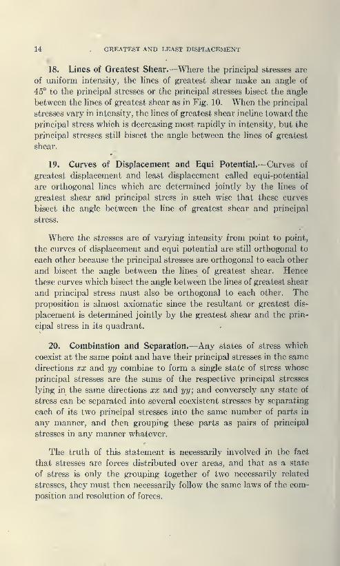
18. Lines of Greatest Shear.—Where the principal stresses are
of uniform intensity, the hnes of greatest shear make an angle of
45° to the principal stresses or the principal stresses bisect the angle
between the lines of greatest shear as in Fig. 10. When the principal
stresses vary in intensity, the lines of greatest shear incline toward the
principal stress which is decreasing most rapidly in intensity, but the
principal stresses still bisect the angle between the lines of greatest
shear.
19. Curves of Displacement and Equi Potential.—Curves of
greatest displacement and least displacement called equi-potential
are orthogonal lines which are determined jointly by the lines of
greatest shear and principal stress in such wise that these curves
bisect the angle between the line of greatest shear and principal
stress.
Where the stresses are of varying intensity from point to point,
the curves of displacement and equi potential are still orthogonal to
each other because the principal stresses are orthogonal to each other
and bisect the angle between the lines of greatest shear. Hence
these curves which bisect the angle between the lines of greatest shear
and principal stress must also be orthogonal to each other. The
proposition is almost axiomatic since the resultant or greatest dis-
placement is determined jointly by the greatest shear and the prin-
cipal stress in its quadrant.
20. Combination and Separation.—Any states of stress which
coexist at the same point and have their principal stresses in the same
directions xx and yy combine to form a single state of stress whose
principal stresses are the sums of the respective principal stresses
lying in the same directions xx and yy; and conversely any state of
stress can be separated into several coexistent stresses by separating
each of its two principal stresses into the same number of parts in
any manner, and then grouping these parts as pairs of principal
stresses in any manner whatever.
The truth of this statement is necessarily involved in the fact
that stresses are forces distributed over areas, and that as a state
of stress is only the grouping together of two necessarily related
stresses, they must then necessarily follow the same laws of the com-
position and resolution of forces.

COMBINATION AND SEPERATION 15
For the sake of brevity, we shall iise the following nomenclature
of which the meaning will appear without further explanation:
The terms apf>iifHi to
force« and stn'sws arcConj|K)ini<l
ComptMttiunComponent
ResolutioDResultant
The toniw applio<l to
states of stress are:-
CombineCombinationCmnponent stateSeparateSeparationResultant state
(Eddy Researches Graphic Statics)
Problem.—Given any state of stress defined by two principal
stresses px and py to find the direction of obliquity of the stress ujwn
any plane thru O whose trace on xy is AB.
Let OX and OY] \)c the directions of the principal stresses, Fig.
II and Fig 12 OX lieing the direction of the greater stress.
Let Px be the intensity of the greater stress:
Let Py be the intensity of the lesser stress:
Fi«. II Flh. 12
Fig. II repreeentB the case where the principal stresses are of
like sign and Fig. 12 where they are of unlike sign.
Separate the state of stress into a fluid stress whose intensity
Px+Pyri OM laid off normal to AB. With radius OM draw a
circle of stress intersecting OK at (?. Draw QM extended. With* Px—Py
radius rt»
—
x—- describe a circle of right shearing stress of about
M tM& center and the intersection of QM with this circle will fix the
point R. Connect HO; then will tiO represent the intensity, direction
and obliquity of the stress upon i4B at the point O.

16 CONSERVATION OF STRESS AREAS
Thus the locus of the point M as the plane -45 is revolved in a
circle of the radius of —- represents the fluid stress into which
the state of stress defined by the principal stresses Px and Py has
been separated and MR the radius of the circle of right shearing
stress as its conjugate component. The locus of the point R is the
ellipse of stress otherwise derived from the law of variation of tan-
gents of ellipse and circles of stress in Art. 15.
The intensity of OR = ^Px^ . Cos^ XON + Py sin^ XON.
The principal stresses being represented by the semi axes of the
ellipse are the greatest and least of the plane stresses in XOY. Thedirect and shearing or normal and tangential components are found
by letting fall a perpendicular from R upon OM as ol ows
:
^\ ^\(a) Direct or normal Pn= Pa:cosWOX+Pi/sfwWOX.
(6) Shearing or tangential Pt= (Px— Py)cosNOXsinNOX.
From (a) the sum of the normal stresses on any two planes at
right angles to each other normal to xy thru is equal.
From (6) appears the equality of shearing stresses upon any pair
of planes at right angles to each other, thru normal to the plane XY.
(This relation was first demonstrated by Cauchy.)
21. The Principal of Conservation of Maximum and MinimumFiber Stress Areas within the ellipse of stress appears at once from
the discussion of Art. 19.
The plane of action of the lesser principal stress is the major axis
and its stress area =Py times 20X. The plane of action of the
greater principal stress is 20Y and its area = Pa:X20 F.
Since Px : Pyy.OX :0Y by construction, therefore the maximumstress area PxX20Y =PyX20X the minimum stress area. In like
manner it may be shown that within the ellipse of stress the major
and minor normal fiber stress areas in a plane thru upon any ortho-
gonal pair of planes normal to the plane of stress XOY are numeri-
cally equal

17
CHAPTER II
ACTION OF EXTERNAL FORCES AND REACTIONSOF ELASTIC RESISTANCE.
1. The applied forces distributed over the cro88 section of the
resisting material perform the work of deformation against the
elastic resistance of the material. By Newton's third law, this
action and reaction are equal and opposite to each other.
Since mechanical work is the product of a force times the distance
through which its point of appHcation moves against resistance,
the EXTERNAL WORK OF THE LOAD is its mean intensity
multipUed by the deflection of the elastic structure or deformation
of the material in the direction of its application.
Conversely, the INTERNAL WORK OF DEFORMATIONof a unit of material is the product of the mean stress times the strain
deformation produced by the stress and the total work of deformation
is the sum total of the work of deforming the several parts or all the
units of the specimen.
2. Energy (Mech.) is a term used to define capacity for per-
forming work, distinguished as kinetic or actual energy in reference
to the work which in a given case it actually performs; and as po-
tential energy in reference to the work which it is capable of performing
if fully exerted.
Actual energ}' is exemplified in tiie vis viva (active energy) of
moving bodies in heat, electric currents, etc. Potential energy
is exemplifie<l in the resistance of a spring bent downward by a
gradually applied load ready to raise the mean load as it is gradually
removed the same amount that during loading the position of tin
mean load was lowered. It requires mechanical work to pumpwater to any height and when so pumped up it has energ>' of position
capable of doing work as it runs down to a lower level as through a
turbine wheel.
In the case of a spring or beam bent downward under a gradually
applied load, the decrease of potential encrgj' of position of the load
by loss of height is stored up in the elastic resistance of the spring or
beam ready to be entirely restored in raising the load during gradual
removal if the spring or IxMim be perfectly elastic. But if it be
imperfectly elastic, then some part of the energy of position lost by

18 ANALYSIS
the load cannot be restored to the load during gradual unloading
because it has been transformed into heat in overcoming non-elastic
resistance within the spring or beam. It is then lost with respect
to the system embodying the load and spring only but not destroyed
since the heat has been radiated to the surrounding air.
In the case of the water tower, actual energy expended in raising
the water by pumping is stored as potential energy by increased
head of the water in its elevated position.
A transfer of energy from one part of an elastic system to the
other occurs under 'change of load but the total gain or loss in one
part is exactly equivalent to the loss or gain of the remainder in accord
with the fundamental law that energy may be changed in form but
cannot be destroyed.
Applied to a bridge it expresses the relation that the loss of energy
of position of the loads by deflection is transformed by the elastic
resistance of the structure into internal work of deformation.
3. Analysis.—The principle explained in Art. 2, is of great value
in the analysis of stress and computation of deflection of structural
members under applied loads. The method of analysis based directly
thereon is termed The Theory of Work.
ANALYSIS BY THE GEOMETRY OF ELASTIC DE-FORMATION is founded upon proportionality of cause and effect-
When the cause of deformation is stated in units of mechanical workthen elastic opposing resistance may be expressed in the same units,
and is equal thereto if no work has been done in permanently changing
the structure of the substance.
This may be shown experimentally by loading a spring balance
on which each division of the scale represents one ounce with a
quantity of shot. By placing sixteen grains (weight one ounce) on
the pan, the pointer indicates a certain downward motion of the
spring registered as one division or ounce on the scale. Placing
sixteen more on the pan, a further downward motion of another
space occurs, and two divisions are registered, and so on until with
256 shot on the pan it registers sixteen divisions or ounces. If now,
the shot be removed grain by grain, on the removal of 16 shot, the
spring has moved 240 grains of shot up one space and the dial in-
dicates 15 ounces. If we remove 16 more, the spring moves 224
grains upward one space more and registers fourteen divisions or
ounces, and so on until they are all removed.
The mechanical work of the mean weight times its downwardmotion during gradual loading of the spring equals the mechanical

rlrecedappUec
BLAflTIC LIMIT 19
work, i. e., prcxluct of the mean load times the distance through
which it is raised by the spring during the step by step process of
loading. Therefore, the external work of the load equals the
internal work of deformation stored in the spring as shown
performance in raising the load as step by step removal took
Since the static work of elastic deformation equals the sum of
all mean stress times the corresponding strain equals the gradually
applied mean load times the downward motion in loading and pro-
portional relations exist between the load and deflection, stress
intensity and magnitude of strain must be likewise proportional.
The foregoing elastic relation is known as Hooke'a Law first
published by Robert Hooke, in 1678,—Ut tensio sic vis, as the
extension, so the jresistance, or freely translated, "Elxtension is
proportional to force (applied)."
4. Elastic Limit.—The reversible cycle of the exi>orinient of the
ing article shows that the elastic limit is that range of gradually
appUed loading within which the elastic deformation stores up tiic
entire external work of the applied load in such manner that it can
restore this energy in the step by step process of unloading. When it
IB exceeded the deformation cannot be wholly expressed in units of
the same kind of energy lxH;ause a part of the external work has
been expended in over coming non-elastic resistance and has been
converted to and dissipated in heat units which cannot follow the
reversible cycle.
Elastic return to the original form or shape after strain is a
characteristic deportment when stress is kept within the elastic
limit. But it in no wise conjstitutes a detenninant of that limit since
return to the original fonn may be unaccompanied by the capacity
to restore the work of deformation. A constant ratio of the magni-
t!ide of deformation to the intensity of the applied load or forct*
producing the deformation is a true determinant so that the true
elastic limit is also a Limit of Proportionality, as well.
The limits of elasticity for steel and materials of construction are
80 narrow that the distance l)etween any two neighboring points of
the substance never alters more than a very small profxirtion of its
own amount without either bn^aking or experiencing a permanent
aet or inelastic deformation.
For ordinary steel the elastic elongation or shortening before
nt set takes place varies from 1/800th to 1/ 1000th of the
and the angular distortion not far from two tenths of a degree.

20 POTENTIAL ENERGY OF DEFORMATION
It accordingly appears that the determination of the elastic limit
experimentally by the determinant of proportionality gives
approximate values because of the small magnitude of the elastic
strains involved and the difficulty in making sufficiently precise
measurements.
5. Potential Energy of Deformation.—An elastic body in a given
state of strain is capable of doing a certain amount of work against
external resistance as in the experiment in unloading the spring
balance. Under the principles of statics of abstract forces this
work of raising the load during the process of gradual removal would
constitute the potential enfergy of the state of strain which the spring
had undergone during the process of loading. Elastic reactions to
applied forces, however, exhibit strain components normal to the
applied forces and since no static component exists in the normal
direction the principles of statics of external forces do not quantatively
fix the potential energy of deformation as equal to the energy expended
by the applied force or load. Since the latter energy comprises the
sole external source the body itself must have suffered a transfer of
kinetic internal energy to make up this apparent increase of internal
potential energy of deformation by lateral deformation.
Now the kinetic internal molecular energy of any substance is
measured by its temperature and its relation to stress and strain
will now be investigated.
6. The Mathematical Theory of the Thermo-EIastic Proper-
ties of Matter has been developed by Kelvin, (Quarterly Mathema-
tical Journal, April 1855) and the following formula which is ap-
plicable to a metal bar is there demonstrated:
t p eH =JSW'
where iy= thermal change in degrees Centigrade;
< = temperature. Centigrade, from absolute zero;
J = the mechanical equivalent of the thermal unit, = 1400 ft.
lbs. per degree Centigrade;
p= pressure applied, in pounds, positive if compression and
negative if tension;
e = the longitudinal expansion per degree Centigrade;
<S = the specific heat;
and W= the weight, in pounds per foot of length of bar,
A digest of Kelvin's work in Thermo Dynamic Theory is given in Tod-
hunter & Pearson's History of Strength and Elasticity, Vol. II, Chapter 14.

THBBMO KLF.CTRIC MKASinUElfENT Of SnUMM 21
This change in temperature, as would be inferred from the mechan-
ical theory of heat, takes place instantaneously, with the application
of the pressure, or load, p, and is subject to the usual laws of radiation.
Since the temperature change is verj' small, Newton's Law of Cooling
may be taken to apply exactly, namely ; The amount of heat gained
or lost by a body in a given time is proportional to the difference in
temperature between the body and the surrounding medium. Hence
if two loads, of different magnitudes, are gradually applied in equal
periods of time, the temperature changes in the bar for the respec-
tive loads will be strictly in proportion to the loads, notwithstanding
the radiation going on while the loads are being applied.
The formula
ti ' P*"I vnr iwigidly exact for any solid only for an infinitesimalJon
increment in p; but with steel, any variation from it within elastic
limits would be extremely small, and may be taken as exactly pro-
portional to the pressure or load applied, and, as we are interested
only in relative measurements, no error is involved.
As H depends on (, the temperature of the bar at the time the
load is applied, this temperature should be noted, if readings taken
at diflferent temperatures are to be compared. Thus, if the value
of absolute zero be taken at —276.7* Gent., and one set of measure-
ments is taken at 23.3*' Cent., and another at 24.3" Cent., the latter,
for the same loads, should be l/3 of 1% greater, if no error has been
made in the determination. As t would probably not vary greatly,
this percentage per d^^ree Centigrade is sufficiently accurate for
most purposes.
The magnitude of the temperature change, H, may be best
illustrated by a few figures. Take the temperature of a bar at 19.3®
Cent., p at 1 lb., and the area of the bar at 1 sq. in., and we have,
for mild steel,
^^ (276.7. 19.3)X1.0X .00001142.0.00000623 Cent., the tern-
1400X0.116X3.34
perature change for a change in stress of 1 lb. per square inch.
Such minute temperature changes as those resulting from the
application of a load of even one quarter ounce per square inch maybe measured by thcrmo electric means and it is therefore possible to
determine the range of true elasticity of such a homogeneous material
M steel by this method with a high degree of precision. Such mea-
22 THERMO-ELECTRIC MEASUREMENTS
surements and the apparatus employed have been described by
the author, (Trans. Am. Soc. C. E., August 1902). The apparatus
used was an antimony-bismuth thermopile, insulated from and ap-
pUed to the polished surface of the specimen, in circuit with a
D'Arsonval type of galvanometer with the usual scale and reading
telescope fordetermination of the relative intensity of the current
produced by different loads.
Suitable insulation of the thermo-pile from the animal heat of the
observer, from radiant heat of electric light, and disturbing air cur-
rents is essential as well as the insulation of the pile to prevent any
short circuit from contact with the polished surface of the bar.
Material for the latter insulation was the subject of much study,
rubber cement proving the most available material since it gave an
exceedingly thin coat which did not interfere with the transmission
of heat and effectually prevented short circuit.
It was found necessary to vibrate the scale beam of the testing
machine in order that the weighing of the load should correspond
with the degree of accuracy of the electrical measurements. Fromthese experiments Turner shows that the limit of thermal propor-
tionality in mild and medium steel is approximately five eighths of the
yield point value of the metal. The bar was found to grow gradually
cooler under increased loading until this Umit was reached when the
heat generated by internal molecular friction off-set the increment of
reduced temperature and the thermal curve deviated from a straight
line more and more until the yield point value was reached when the
sudden evolution of heat at that point would make the reading
fall beyond the scale.
So in compression tests. The readings were found to be propor-
tional up to approximately a similar limit when the increase in tem-
perature of the bar would no longer follow the right line changes but
would increase more and more rapidly as the yield point was ap-
proached but at that point the reading would be too great to fall
within the limits of the scale.
By the foregoing formula we may proceed to compute approxi-
mately the relation of the heat transformed from kinetic energy of
molecular vibration to potential energy of elestic strain and com-
pare its amount with the work of the mean external force or pull
times the stretch of a bar of steel.
Take the section 1" square; E, the ratio of unit pull divided byunit stretch, at 30,000,000; applied pull 10,000 lbs. per square inch.
OBOMmUC AND CTTATIC MODVUl 23
a foot, Ellongation e4
1000
External Ener^' = Q. - 002 X 10,000 = 20 in. lbs.
Internal Energ\- = 00000623 X 10,000 X 1400 X .116 X 3.34 =.3 in. lbs. = 34.7 lb. ins. = (?,.
As the transfer of kinetic internal molecular energy to the
potential energy of strain or vice versa is much greater than the
applied energy of the external forces it immediately appears that
temperature change under stress is an important factor or partial
determinant in fixing the final change in form or shape of an elastic
body under stress.
As the temperature is lowered by pull below that of the sur-
rounding air by radiation therefrom (the stress remaining con.stant
meanwhile) the temperature i.s brought back to its original amountIx'fore strain, e. g., the elastic material ha.s received energy from
without. Conversely if the strain Ix? compression by radiation more
energ\' has been dissipated than expended in compressing the bar,
to Ik* returned to it again by radiation from the surrounding air in
the reversible cycle of loading and unloading.
Since the ultimate ratio of .static stress and strain is in part a
thermal function, the relations of stress and strain present two dif-
ferent aspects or ratios.
—
(/) A geometric ratio (called kinetic by Kelvin in Elasticity,
Eney. Brit.,) which is the instantaneous ratio of ela.<<tic stress divided
by the strain, and
{2) A static or thermal ratio which represents the final static
after the 8traine<l sj)ecimen through radiation from or to the sur-
rounding unchanged metlium has arrivinl at the temperature thereof.
These ratios will be termed respectively the GEOMETRIC(i. e., kinetic) and STATIC MODULI I OF ELASTICITY.
The so-called lag of strain in reaching the final or statu -laic
follows Newton's law of radiation.
The rapid decay of clastic vibration is predominantly cau.sed
not by viscosity or friction with the external air l)ut by the necessiiry
transferance in elastic change of fonn of nearly double the quantity
of kinetic energj' of molcn-ular vibration in heat units to potential
energy of strain.

24
CHAPTER III.
THE MECHANICS OF ELASTICITY.
1. A body is said to be HOMOGENEOUS when the material
is of the same kind or nature throughout. A strain is said to be
HOMOGENEOUS when parallel lines thru the same particles before
strain remain parallel after strain.
Uniform intensity of both principal stresses in a plane cause
homogeneous states of strain. Varying intensity of both principal
stresses cause heterogeneous states of strain in which parallel lines
in the body before strain are no longer parallel after strain.
A body is said to be ISOTROPIC when it presents the same
elastic properties in all directions. Such a body rigidly obeys Hooke's
law, and opposes equal resistance to stress in all directions.
Fibrous materials and metals which have been heavily rolled, or
otherwise over strained differently in different directions are un-
equally strong in these respective directions and are said to be
EOLOTROPIC.The investigation will deal first with the properties of the ideal
isotropic material and then follow as far as possible the cause of
Eolotropy and the resulting modification in resistance and deport-
ment of material incident thereto.
2. The Kinetic or Geometric Modulus of the stress strain
relation is to be determined from the geometric relations of the lines
of principal stress and greatest shear to the curves of resultant dis-
placement and equi potential. Conversely, the relative geometric
modulus may be derived by separation of the state of strain in a plane
into the four states of displacement of which any given state of strain
is the resultant. See Art. 18 and 19, Chapter I.
The simplest case of homogeneous strain will now be considered
:
Let a flat bar. Fig. 13, be subject to an axial pull P:
/=-<3L-kve<-A--4?^^%^'->|-~^^P
Fig. 13
wI
ELLIPSES or DISPLACEMENT 25
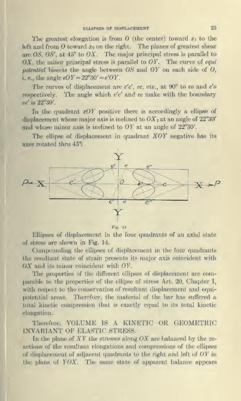
The greatest elongation is from (the center) toward Xi to the
left and from O toward Xj on the right. The planes of greatrat shear
are OS, 0S\ at 45* to OX. The major principal stress is parallel to
OX, the minor principal stress is parallel to OY. TTie curve of equi
potentUjd bisects the angle between OS and OK on each side of O,
i. e., the angle eOr = 22*30' -e'OF.
The curves of displacement are e'c', ec, etc., at 90* to eo and e'o
respectively. The angle which e'c' and ec make with the boundary
ee' is 22*30'.
In the quadrant xOY positive there is accordingly a ellipse of
displacement whose major axis is inclined to OXt at an angle of 22*30'
and whose minor axis is incUned to OY at an angle of 22*30'.
The ellipse of displacement in quadrant XOY n^ative has its
axes rotated thru 45*i
/^x
Tlijr 14
Ellipses of dLspIacciiunit in the four quadrants of an axial state
of stress are shown in Fig. 14.
Compounding the ellipses of displacement in the four quadrants
the resultant state of strain prc^sents its major axis coincident with
OX and it.s minor coincident with OY.
The pro|>erties of the different ellii>ses of displacement are com-
parable to the properties of the ellipse of stress Art. 20, Chapter I,
with respect to the consc^rvat ion of resultant displacement and equi-
potential areas. Therefon-, tin m.itt ii;il of the bar has sufTere<l a
total kinetic compression that is cx.Ktlx ('(jual to its total kinetic
elongation.
Therefore, VOLUME IS A KINETIC OR GEOMETRICINVARIANT OP^ ELASTIC STRESS.
In the plane of AT the stresses along OX are balanccHJ by ihc re-
actions of the resultant elongations and com|)ressions of the elli|)se8
of displacement of adjacent quadrants to the right and left of OY in
the plane of YO\. The same state of apparent balance appears

26 ELASTIC MODULII
statically in the normal plane of ZOX and accordingly this double
potential of strain must draw its energy from the intrinsic energy
of molecular vibration or heat of the body in the original state of
zero stress. The potential energy of the strain in the isotropic
uniform solid is momentarily twice as great as the quantity of energy
expended in producing the strain. But the intrinsic heat energy of
the unstrained body has suffered a loss equal to twice the external
work of deformation.
3. Young's Mpdulus E and Poisson's Ratio K.—(Kinetic)
While in the ellipse of displacement of the isotropic elastic body
strain is strictly proportional to stress, the axes of this ellipse are not
parallel to the boundary of the bar and it is desirable to know the
elongation in the direction of the pull rather than along the curve
of resultant displacement ; also the contraction normal to the bound-
ary plane rather than along the curves of equi-potential. The
elongation in the direction of the pull is figured as unit pull over the
coefficient E called Young's Modulus. The isotropic relation of Eto the coefficient of lateral contraction may be determined from the
principle that volume is a kinetic invarient of the elastic strain as
follows:
Let dx be a small increment of elongation
;
Let dy be the corresponding increment of lateral contraction;
Then for kinetic invarience
(l+dx)il-dyr=la-\-dx)il-2dy-\-dy') = l.
Evaluating dy/dx = Al'i2 = tan22°S0' equals the angle of incli-
nation of the curve of displacement to the boundary plane, equals
the ratio of unit lateral contraction divided by unit elongation in the
direction of the pull P= the coefficient K or Poisson's ratio.
Problem : (Let the student determine the same relation from the
geometry of stress curves and the curves of displacement.)
4. Rotational or Shear Resistance is measured by a coefficient
called the Modulus of Rigidity F. As the radius of rotation is the
lever of the force causing rotational displacement or strain the
relative value of F depends on the relative length assigned the lever.
In the case of the bar, Fig. 13, the lateral contraction occurs from the
edges toward the center and the shear distortion is half above and
half below the axis. The squeezing together of the material viewed
from this standpoint is twice as easy as though the rotational dis-
tortion were all in one direction. Thus under axial pull there is no
MODULUS or RIOIDITT 27
applied shear force, hence half P prcxiuces a rotation or action in
one direction and half P produces its reaction in the other direction.
Under transverse stress the actions and reactions are divided between
external rotation and internal shear strain. As compared with the
unit upon which the elongation is conveniently measured the lever
of the shearing force is 1/otw 45, consequently the isotropic relation
of £/F=l/2X 1.414 ».35355+. This value of f is the only value
consistent with the conception of isotropy as opposing equal resist-
ance tb stress in all directions.
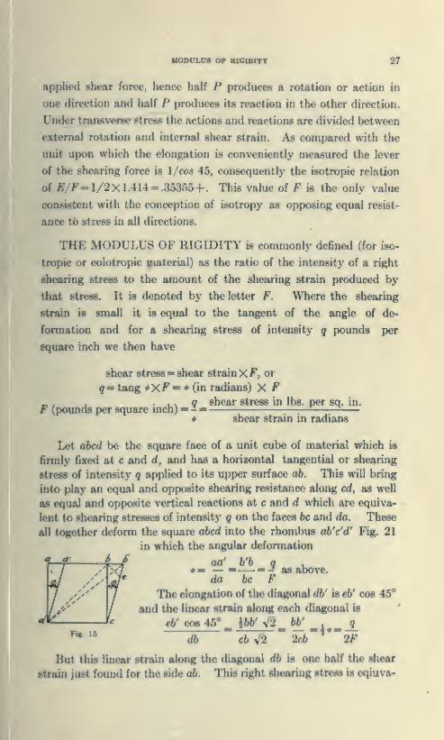
THE MODULUS OF RIGIDITY is commonly defined (for iso-
tropic or eolotropic material) as the ratio of the intensity of a right
shearing stress to the amount of the shearing strain produced by
that stress. It is denoted by the letter F. Where the shearing
ttnin is small it is equal to the tangent of the angle of de-
formation and for a shearing stress of intensity q pounds per
square inch we then have
shear stress = shear strainX F, or
g« tang XF = (in radians) X F
F (pounds per square inch) » -qshear stress in lbs. per sq. in.
shear strain in radians
Let abed be the square face of a unit cube of material which is
firmly fixed at c and d, and has a horizontal tangential or shearing
stress of intensity q applied to its upper surface ab. This will bring
into play an equal and opposite shearing resistance along cd, as well
as equal and opposite vertical reactions at c and d which are equiva-
lent to shearing stresses of intensity q on the faces he and da. These
all together deform the square abed into the rhombus ab'e'd' Fig. 21
in which the angular defonnation
aa' b'b q» — ——— - as above,da 6c F
The elongation of the diagonal db' is e6' ooe 45**
and the linear strain along each diagonal is
e6^ co6 45'' _ hbb' yl2 _bb' _,^__9."c6V2 " -•"'*"-"
db 2cb 2F
But this linear strain along the diagonal db is one half the shear
strain just found for the side ab. This right shearing stress is eqiuva-
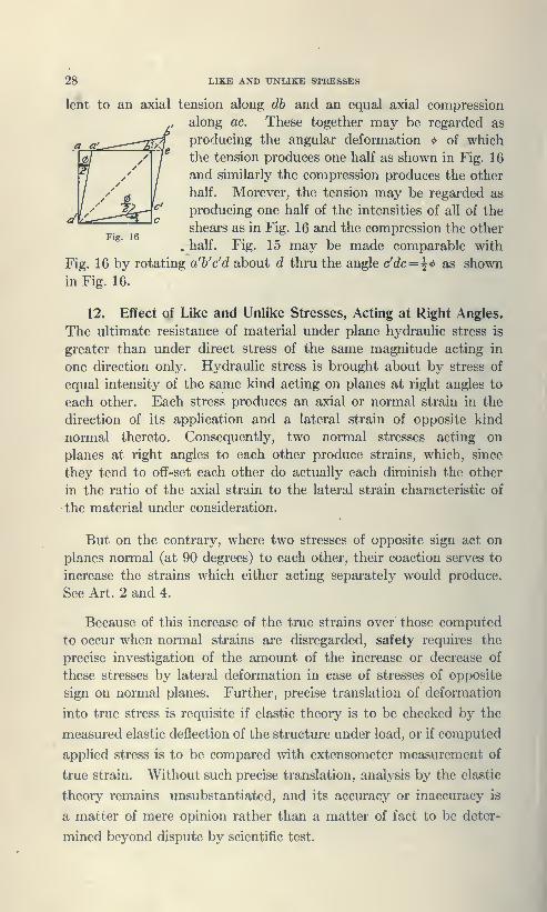
28 LIKE AND UNLIKE STRESSES
lent to an axial tension along dh and an equal axial compression
along ac. These together may be regarded as
producing the angular deformation <t> of which
the tension produces one half as shown in Fig. 16
and similarly the compression produces the other
half. Morever, the tension may be regarded as
producing one half of the intensities of all of the
shears as in Fig. 16 and the compression the other
. half. Fig. 15 may be made comparable with
Fig. 16 by rotating a'h'c'd about d thru the angle c'dc = ^'t> as shown
in Fig. 16.
12. Effect of Like and Unlike Stresses, Acting at Right Angles.
The ultimate resistance of material under plane hydraulic stress is
greater than under direct stress of the same magnitude acting in
one direction only. Hydraulic stress is brought about by stress of
equal intensity of the same kind acting on planes at right angles to
each other. Each stress produces an axial or normal strain in the
direction of its application and a lateral strain of opposite kind
normal thereto. Consequently, two normal stresses acting on
planes at right angles to each other produce strains, which, since
they tend to off-set each other do actually each diminish the other
in the ratio of the axial strain to the lateral strain characteristic of
the material under consideration.
But on the contrary, where two stresses of opposite sign act on
planes normal (at 90 degrees) to each other, their coaction serves to
increase the strains which either acting separately would produce.
See Art. 2 and 4.
Because of this increase of the true strains over those computed
to occur when normal strains are disregarded, safety requires the
precise investigation of the amount of the increase or decrease of
these stresses by lateral deformation in case of stresses of opposite
sign on normal planes. Further, precise translation of deformation
into true stress is requisite if elastic theory is to be checked by the
measured elastic deflection of the structure under load, or if computed
applied stress is to be compared with extensometer measurement of
true strain. Without such precise translation, analysis by the elastic
theory remains unsubstantiated, and its accuracy or inaccuracy is
a matter of mere opinion rather than a matter of fact to be deter-
mined beyond dispute by scientific test.

DrrKKMINATION OF TH0S STBSflS 29
On The Determination of Troe Stresses From The Measured
Strains by Help of Elastic Coefficients
The modulus of elasticity E as just defined is the longitudinal
unit stress p acting along x say, divided by the corresponding longi-
tudinal unit strain e, in the same direction, viz. E^p/e, on the
cxprcflB condition that there is no lateral applied stress perpendicular
thereto along either y or z. Hence longitudinal stresses can be
correctly calculated as the product of the observed longitudinal
strain e and the modulus E only in case there are no lateral forces
acting along either y or z.
In this case of simple longitudinal stress there is, however, a
lateral deformation or unit strain amounting to —Ke along both y
and 2, and the appartnt or applied stress p acting along x produces
not only the longitudinal strain e along x but also two lateral strains
each equal to —Ke along y and z respectively.
In order to find out how much longitudinal strain the stress pwould produce in its own direction x were it not also employed in
producing lateral strain along y, let us superpose on the body a
lateral stress of intensity -i-Kp along y while the stresB along z re-
mains unchanged at zero. This applied stress of +Kp along y when
acting alone produces a lateral strain +Ke along y and —iC^e along
z, but when acting in conjunction with the existing lateral strain
—Ke makes the resultant deformation along y vanish, while the total
strain along z i^^nll be due to the stress p along z and to Kp along y,
and hence will amount to —K{1 +K)p along z.
This deformation +Ke along y which has been superposed on
the body is necessarily accompanied by a superposed strain of
—K^e along Iwth x and z.
Hence the resultant strain along x due to the longitudinal stress
p when lateral strain along y is entirely prevented and no stress is
applied along z, amounts to (1
—
K?)e, and the true stress along x as
indicated by extensometer measurements of the strain will l)e pi —
(1—/iC*)p« (1
—
K^Ee, which is the intensity of that part of the total
applied sUess p as calculated by help of E which produces strain in
its own direction x. The rest of the applie<l strcjw along x, viz.
+K^p is held in equilibrium by resistance to lateral flow n^presented
by the lateral stress —Kp.
The forgoing calculation of tmo Ktreas along x upplii^s to all cases
where the intensity of the lateral stress actually applied along y is
such as to prevent deformation along y, while that along z is neg>
30 ELASTIC CONSTANTS
ligible, under which conditions the true stress tending to deform the
body in the direction of x does not exceed (1
—
K^)p and the strain
in that direction does not exceed (1
—
K^)p/E.
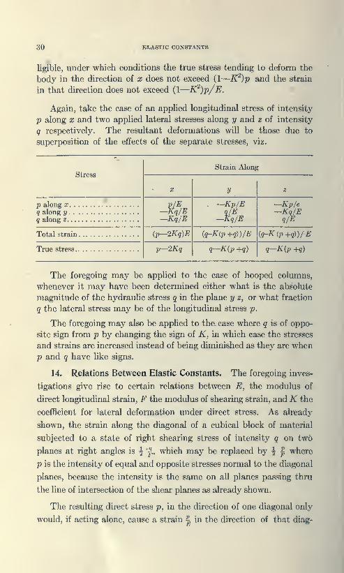
Again, take the case of an appUed longitudinal stress of intensity
p along X and two applied lateral stresses along y and z of intensity
q respectively. The resultant deformations will be those due to
superposition of the effects of the separate stresses, viz.
Stress
p along X. . .
q along y. . ,
q along z
Total strain
,
True stress..
p/E—Kq/E—Kq/E
ip-2Kq)E
p—2Kq
Strain Along
y
—Kp/Eq/E
—Kq/E
{q-K{p +q))/E
q—Kip +q)
—Kp/e—Kq/Eq/E
iq-K(p+q))/E
q—K{p +q)
The foregoing may be applied to the case of hooped columns,
whenever it may have been determined either what is the absolute
magnitude of the hydraulic stress q in the plane y z, or what fraction
q the lateral stress may be of the longitudinal stress p.
The foregoing may also be applied to the. case where q is of oppo-
site sign from p by changing the sign of K, in which case the stresses
and strains are increased instead of being diminished as they are when
p and q have like signs.
14. Relations Between Elastic Constants. The foregoing inves-
tigations give rise to certain relations between E, the modulus of
direct longitudinal strain, F the modulus of shearing strain, and K the
coefficient for lateral deformation under direct stress. As already
shown, the strain along the diagonal of a cubical block of material
subjected to a state of right shearing stress of intensity q on two
planes at right angles is ^ ^(„ which may be replaced by ^ | where
p is the intensity of equal and opposite stresses normal to the diagonal
planes, because the intensity is the same on all planes passing thru
the Una of intersection of the shear planes as already shown.
The resulting direct stress p, in the direction of one diagonal only
would, if acting alone, cause a strain | in the direction of that diag-

MBCBAKICAL WOKS 31
onal, while the oppodte kind of direct stress in the direction of the
other diagonal perpendicular to the first, would, acting alone, cause
i* similar kind of strain to the above, amounting to /CX| in the
tion of the first mentioned diagonal. But each of these direct
fliraixui would be accompanied by a lateral strain of the opposite
sign amounting to Kp/E. It is to be noticed that the two strains
J: Kp/E at right angles to the plane of the right shearing stress annul
each other. Hence the total strain along either diagonal is
from which
'f e
^--—(1+/02F E
F
For steel as received from the mill
—
£= 3(10)'A' = .3andF=115(10)»= 3846£r.
When relieved from internal stress by repetition of stress from ten-
sion to compression of low intensity K approaches .4142 and Fwhile E increases toward 315(10)» from 3(10)'. )See
i... . ...nger's exporimont.«<).
8. Kinetk and Statk: Modulii Compared.—To find the ratio of
the kinetic or geometric to the thennal or static modulus the dimu-
nition of strain due to the temperature change //, equals eH. Hence
if E' denotes the static modulus the strain when the body is not
allowed to gain or lose heat is p/E'—eH, or with H replaced by its
value
E' 'JWSDividing p by this expression, the kinetic modulus =
Sr L_i ~ *^E' JWS
In Art. EHasticity, EInc. Brit., Kelvin gives for compression
J?- 1.00259 for iron
E' 1.00325 for copper
These differences, though small, are of sufficient magnitude to be
oonaidered in any precise experimental investigation.
9. Summary: From the foregoing development, the true value
of K for a constant volume has been geometrically determined and

32 SUMMARY
the relation of curves of displacement to the lines of principal stress
and greatest shear developed for the first time.
The value of potential of elastic strain was not understood bythe founders of the mathematical theory of elasticity, Navier, Poisson,
and Cauchy, and for that reason they supposed the true value of Kto be .25 instead of .4142. They derived these equations from
Boscovich's hypothesis of intermolecular action. A review of their
work correcting it in the light of the double transfer of Kinetic energy
of vibration to strain potential would have led them to the results
here presented and avoided the fruitless controversy between the
rari and multi constant schools of elasticians as Pearson has desig-
nated them in his great treatise.
Proof has been adduced for the first time that an isotropic solid
can have but one independent coefficient of elasticity.
33
CHAPTER IV.
PHYSICAL PROPERTIES OF MATERIALS OFCONSTRUCTION, THEIR FITNRSS FOR
DIFFERENT KINDS OF SERVICE,WORKABILITY AND SAFETY.
i. Properties.—A material is said to be ductile when it can be
drawn out or elongated a considerable percentage of its length
before final fracture. It is said to be brittle when it breaks without
such plastic elongation or snaps short under a blow or shock. As
the hardness of the material increases as a rule its ductility
decreases. Thus, soft steel will stretch twenty five or thirty percent
of its length before fracture, while hard tool steel shows little plastic
deformation before nipture. Cast iron for example snaps in tension
without noticeable plastic elongation. Building stone, which is
relatively hard, strong in compression and shear, is brittle and
unreliable in tension.
That material is preferred for resisting axial tension or Ix'nding
in which the ultimate resistance in tension and compression is equal.
Thus, mild steel, which has equal resistance in tension and compres-
sion, is most suitable for resisting axial tension or bending. Brick,
stone and artificial stone, such as concrete, which present reliable
compressive resistance, are used in masonry. Cast iron, which in
the pn.'<t centurj' was u.sed extensively for lintels, and cohnnns in
buildings, is being replaced by structural steel though still most
extensively employed for machinery, cylinders, gears, pipe, fittings,
grate bars, stoves and furnace castings.
The following brief outline of the projjerties of materials will
deal more particularly with the characteristics which are related
to elasticity and which cause variation in their strength, toughn(»8s
and utility.
2. Brick is made of bunied clay. The clay is prepared by
mixing with water, moulding into the desired form by hand or machine
and after the brick are dry they are placed in the kiln and burmnl
until those nearest the fuel lissume a partially vitrified ap|M>arance.
The quality of the brick taken from the kiln are first, arch brick,
those forme<l around the arches forming the furnac<» chamln'r of the
kiln, iKxJy brick fnmi the interior, s<jft brick from the exterior.
Arch brick are hard and often brittle; Ixnly brick are the lH>st
quality, while the soft brick art* suitable only for filling in or backing

34 STONE
up where a high degree of strength is unessentiah The common
size is 2^x4x8j inches. The average weight about 4^ pounds.
Pressed brick may weigh nearly 5^ pounds. Soft brick will commonly
absorb twenty to thirty percent of its weight of water while body
brick about half that amount.
Fire clay makes the strongest and most impervious brick. Since
the strength of soft brick runs as low as five to six hundred pounds,
and the stronger brick up to fifteen thousand pounds per square
inch, statement of av.erage resistance of brick work is of little utility
and a corresponding variation in the modulus of elasticity E occurs
with the corresponding difference in the material. In general it
may be said that the strength of a brick pier laid up on cement
mortar or portland cement mortar is about one third that of the
average individual brick. Brick is never used to resist tensile stress.
Few experiments have been performed to determine its resistance
under such stress. With the softer varieties it is probably not much
greater than eighty to ninety pounds running up to a thousand
pounds or more for better varieties of fire clay brick.
3. Building Stone.—Building stone is divided into three classes,
classes, sedimentary, metamorphic and igneous.
Sandstone, as its name implies, is usually a sand the grains of
which have been chemically cemented together under pressure and
heat. Where the chemical action and heat have been sufl[icient the
sandstone is changed into a quartzite; it varies greatly in strength,
color and durability. In general, it is easy to cut and dress but
where it has been transformed into pure quartzite or that variety
known as Potsdam sandstone it may be hard and correspondingly
difficult to cut. The softer varieties, when first quarried may be
worked with much greater ease after they have been exposed to the
air. In seasoning they grow much harder and stronger. Limestone
is frequently formed from marine shells and varies greatly in strength
and durability. Some oolitic limestone containes layers of clay or
hardened sea bottom slime which causes gradual disintegration when
exposed to the elements.
Marble is a limestone which has undergone a high temperature
and subsequent crystalization. In composition it is nearly pure
carbonate of lime. It is easily worked, can be highly pohshed and
makes desirable building material.
Granite is an igneous rock composed of quartz, feldspar, and
mica, but in that variety called syenite the mica is replaced by horn-
blend. It is strong and durable, provided there is no iron in its

coNcmns 85
makeup. It takes a high polish. Many quarries of syenite have
80 subject to pressure that cleavage planes extend thru the
materiul at convenient intervals for quarrj'ing blocks of desirable
for building purposes.
p, or basalt, is an igneous rock without cleavage. It is hard
and tough, and less suitable for building construction than the prccwl-
ing varieties of stone because of the difficulty in cutting large blocks
to size. The material is of high strength and possesses remark-
able durability and weathering quaUties. Merriman gives the
following table of the average weight, compressive strength and
shearing strength of these four varieties and assigns a modulus of
ela.sticity ranging from 5,000,000 to 10,000,000 pounds per square
inch: ^
Kind

36 MODULUS OF RUPTURE
ous material of equal tensile and compressive resistance. The de-
parture from the stress distribution of homogeneous material as the
section passes from the steel to the concrete, possessing entirely dif-
ferent characteristics, is to be investigated subsequent to the analysis
of homogeneous material under transverse stress, torsion, and com-
bined stresses.
The utility of material such as plain concrete, stone and brick, in
which there is such a wide divergence between the tensile resistance
and the compressive i:esistance, resides in the fact that the shearing
resistance is far greater than the tensile resistance generally. The
principles governing the relations of the tensile and compressive re-
sistance to shear resistance will now be considered.
5. Modulus of Rupture and Ultimate Shearing Resistance in
Materials in Which the Compressive Resistance Greatly Exceeds
the Tensile Resistance.—The conception of the resistance of isotropic
material, presented in Chapter III, Art. 1, and the discussion of the
modulus of rigidity F, Art. 4, might lead to the conclusion, could the
internal stresses be considered like abstract forces acting upon an
elementary prism as tending to approach a value between two and
three times as great as the tensile resistance if ultimate failure could
be attributed to mere lack of tensile strength. But as tension and
compression approach equal values under the conception of the iso-
tropic resistance, the material should present the same resistance to
shear that it does to either tension or compression. Again, since
shearing distortion is made up jointly of tensile and compressive re-
sistance, and even when over strained in tension, the tensile stress
volume must still equal that in compression, a shift in the position of
the neutral plane necessarily occurs in order to make up this balance
of resistance.
The value of the elastic fiber stress which would furnish the same
resistance at failure is called the modulus of rupture in transverse
bending and is equivalent to the resistance of pure shear at rupture,
this value appears to be a geometric mean between the value of the
ultimate resistance in. tension and that in compression. Thus cast
iron, having a tensile resistance of 20,000 pounds per square inch; and
compression resistance of 80,000 pounds per square inch, the modulus
of rupture should be about 40,000 pounds on a one inch square bar
under concentrated load. This relation is the geometric modulus
for a state of ease—i.e., it is modified by a state of shrinkage strain.
In the concrete beams tested by the Bureau of Standards, in manysamples the loads were concentrated at the quarter or third points.

TIMBBB 37
With such distribution the modulus of rupture would be less than the
geometric mean because while the moment is constant from mid span
to the load, horizontal »hear doformation increases frf)m zero at mid
'•pan to the load, tending to rtnluce the resistance and indue*' crju-k-
ing of the material under and in the vicinity of the load.
A 1 : 3 : 5 concrete, for example, having an ultimate compressive
pstrength of 2,500 pounds per square inch and a tc-nsile strength of
300 pounds, should have an ultimate shearing resistance as a geo-
metric mean of 80(> pounds per square inch. A 1 :2 : 4 concrete,
having ultimate strength of 3.500 pounds per sciuare inch, and a tensile
strength of 350 pounds, should possess on this basis, an ultimate
shearing resistance of 1 ,107 pounds.
6. Timber.—From the standpoint of the elastician, timber is a
fibrous material, presenting diflferent resistances to stress dependent
on the direction of the grain. Its crushing strength transversely
land longitudinally of the grain are different as is also its shearing
resistance.
While the dividing line Ls not sharp, timlxr is classetl jis soft or
hard wood. Common varieties of the soft wootis are the cone lx»ar-
ing trees such as White Pine, Norway Pine, Hemlock, Spruce,
Douglas Fir, Long and Short Leaf Yellow Pine, Cedar and Cj'press.
The common kinds of hard wood are White, Red and Black Oaks,
Live Oak, Hickorj-, White Ash, Maple, Gum, Locust, Elm, Black
WaUiut, Lignum Vitae, Iron Wood, Mahc^any, Teak.
Hard w(kk1s when cut for timl>er are stripped of the bark which
unless removeil hastens decay. Inside the bark there is a soft
portion made up of thin wall cells which constitute the living or
>wing portion of the tree, called the sjip wtxxl. The inner portion
harder and stiffer than the outer sap wowl. The growth of each
season consists of fillers added to the circle of the sap woo<l. This
growth is more rapid and open in the spring and slower an<l more
compact during th(> sununer, giving rise to peculiar ring marking
of the filers which indicate j'ach year's increase in growth. The
icings inside of the sap wjkmI f(inn the heart wcxxl. They are inter-
ruptetl by radial cells connecting between the center of the tree and
soft tissue of the outside. These radial cells are called the me<lullary
lys. In the Pine, the sap wood consists of forty to sixty |>erc«*nt
fof the cross section of the tree, and the time ntjuiretl for sjip wckhI
to transform into heart wood ranges from a few years with the fir, to
many years with the oak.

38 SEASONING TIMBER
SAWING: The manner in which the lumber is sawed from the
log has a marked influence on its quality and behavior. The methodof sawing is determined by the character of the wood and the purpose
for which it is to be used.
Flat sawing consists in roughing the log tangentially to the
annular rings and finishing with parallel kerfs to the side of the log.
Rift sawing is cutting the boards in such manner that the annular
rings are cut through as nearly as possible in a radial direction.
Rift sawing and flat sliwing give rise to the term edge grain and flat
grain. Edge grain lumber shrinks and checks less, and wears moreevenly and smoothly without slivering than the flat grain lumber.
It is sometimes termed quarter sawed.
NATURAL SEASONING: In the preparation of lumber for
construction purposes, it is necessary to dry it out or season it to
prevent decay and excess shrinking. Natural seasoning consists
in exposing the planks or boards after sawing to a free circulation
of air by piling across three or four narrow strips placed in the opposite
direction to which the layers of plank are placed in parallel. Thetime required for thorough seasoning varies from one to two years,
dependent on the character of the wood.
ARTIFICIAL SEASONING or kiln drying hastens the evapora-
tion of the moisture but tends to impair to some extent the strength
and elasticity of the wood. The timber is stacked in a kiln and
exposed to a current of hot air, the temprature dependent on the
kind and dimensions of the stock. Sometimes the heat is supple-
mented by the employment of vacuum pumps. The temperature
used varies from 100° F., for oak, to 200° F., for Pine.
SHRINKAGE: The average values for lateral shrinkage in
wood are for soft pine, cedar, cypress, etc., three percent; for hard
pine, ash, oak, walnut, maple, locust, or white pine, four to five
percent. Birch, beach, locust, hickory, young oak, five to six percent.
Longitudinal shrinkage is usually less than one per cent.
Timber swells and shrinks with its moisture content. Woodblock pavement has been known to expand five to six inches in swell-
ing of the blocks in a forty foot width.
VARIATION OF STRENGTH WITH MOISTURE: Effect
of thoroughly soaking the timber on its compressive strength is to
reduce it twenty percent or more. In other words, timber is strongest
in tension and compression when it is thoroughly dried out. The

TOUOHNESS OF TIMBER 89
best timber is secured by cutting in the fall and winin, when the
sap is not running.
ELASTICITY AND TOUGHNESS: White oak, white ash,
hickory are exceeclinRly tough and spring^', when the timljer is cut
in its prime and for archery, bows equal to the famous English long
bow may be formed from this timber if cut in its prime. On the
other hand, where the trees are old and past their prime, the timber
loses its toughness and elasticity to a large extent and becomes
brash, or brittle. Failure of wooden automobile wheels in general
is due to brash timber and the failure to properly inspect the stock
before working it up. The following table gives the properties of
common varieties of timber.
PROPERTIES OF TIMBER.
Kind of TimberWt.per
cu. ft
dryLbe.
Oak, Red and Black.
Oak, White
Oak, Live
Hickory.
White AshMapk
Gum
LocuntBlack WalnutLignum Vitac
Iron Wood
WhitewoodMahoganyTeak
Pine.
Fir.
43
46
62
49
4745
37
4438
41 to8360
3035
41 to
6130 to4332
Strength in lbe. per sq. in.
Ten-sion
10,000
15,300
8,200
15,800
14,0009,000
16,500
17,60012,500
11,00015,000
7,00013,00015,000
9,000
12,500
Compression
WithGrain
AcrossGrain
6,000
8,000
9,000
8,500
6,5008,000
8,000
9,3007,500
8,80012,000
4,8007,50012,000
4,800
7,300
BendingModu-lus
of
Rupture
2300
2000
27003200
1900170019001400
7001400NOO1200
9,10015,4006,000
5,40024,3006.30014,200
6,00012,70011,200
12,00012,0(X)
19,000
10,80012,00019,0005,00014,0006.500r2.0(N)
Shearinglbe. per sq. m.
WiththeGrain
1100
7501000
100012004501100
8000
300700500MM)
AcrosstheGrain
2300
8480600078006280
6350
5890
71764828
44 IK
40005000
*Tlw aba** Mbla b oompilad from v»ho«M •tMMlMtl wiirsaB wkieh do not dtM-l<iM< tUu f«-
SMtltnc tb« ooodHloM of Um twU. TIm hidMr valiiM ««« uaqiiMlioaably obuitMol Iron. mmUmwKfim of iMvt wood la pria* ooadiUoa; Um lowor valuoa fran loata of iMvir apccunciu whtAkad aot boos c«t ia prlow ooadMoa. Cuawrratlv. mIo vahMi for iaipoeMd U«b«r m« cKraaoa poaw 83 aad 84.
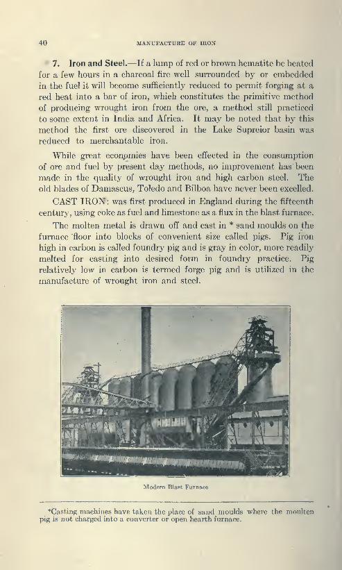
40 MANUFACTURE OF IRON
7. Iron and Steel.—If a lump of red or brown hematite be heated
for a few hours in a charcoal fire well surrounded by or embedded
in the fuel it will become sufficiently reduced to permit forging at a
red heat into a bar of iron, which constitutes the primitive method
of producing wrought iron from the ore, a method still practiced
to some extent in India and Africa. It may be noted that by this
method the first ore discovered in the Lake Supreior basin was
reduced to merchantable iron.
While great econpmies have been effected in the consumption
of ore and fuel by present day methods, no improvement has been
made in the quality of wrought iron and high carbon steel. The
old blades of Damascus,. Toledo and Bilboa have never been excelled.
CAST IRON: was first produced in England during the fifteenth
century, using coke as fuel and limestone as a flux in the blast furnace.
The molten metal is drawn off and cast in * sand moulds on the
furnace floor into blocks of convenient size called pigs. Pig iron
high in carbon is called foundry pig and is gray in color, more readily
melted for casting into desired form in foundry practice. Pig
relatively low in carbon is termed forge pig and is utilized in the
manufacture of wrought iron and steel.
Modern Blast Furnace
Casting machines have taken the place of sand moulds where the moultenpig is not charged into a converter or open hearth furnace.
I
PUDDUNO PROCBM 41
8. Wroufht Iron.—Following the introduction of cast iron
wrought iron wa« more economically produced by the re<iuction of
rge pig in the puddling furnace. The hearth of a reverbratory
18 covered with a layer of high grade ore or mill scale which
acts as an oxidizing agent for reducing impurities. The reduction
occurs at different stages. During the melting down stage muchof the silicon and manganese and .some of the phosphorous are
removed. During the boiling stage under stirring or puddling
most of the carbon and the remaining phosphorous and sulphur are
largely remove<l. As the ma^ becomes purified it assumes a pasty
condition. The metal is then rolled into balls and carried to the
squeeser and there most of the slag is expelled.
The bars from the .first rolling are known as muck bars. These
are cut into lengths, piled, heate<l to a welding heat and rerolled,
and the product is merchant bar iron. If again cut, piled, and
illed the product is called "best" iron. A third rolling gives
t" iron, superior in quality but higher in price.
Prior to 1890, wrought iron was generally employed for structural
purposes but nunlium steel, on account of its smaller cost and greater
uniformity and strength, then came into use so rapidly that it has
today almost entirely displaced wrought iron in bridge and building
ooostruction. Wrought iron is still use<l for machine parts where
its extra cost is more than compen.sated for by its weldability and
the superior toughness of best-best iron under severe service.
Its properties were so thoroughly investigated during the period
of its extensive use in the 19th century that it will long remain in
engineering literature a standard with which other materials maybe compared.
The structure of wrought iron is fibrous in a matrix of ferrous
silicate welded together with an intervening cinder of magnetic
oxide. The percentage of the cinder content varies from one to
one and one half percent. The silicate resists corrosion while the
magnetic oxide if unduly thick in the interior or as surface scale
promotes corrosion. The iron fibers separated by the cintlers
afford a combined resistance to shock superior to soft steel of the
same ultimate strength. The tensile strength of good wrought
iron runs from 46,000 to 50,000 pounds per square inch, its yield
point ahoui 24,000; coefficient of elasticity 25,000,000.
9. Steel.—The di^lsccment of wrought iron came alwut thru
the development, subsequent to 1870, of the Bessemer or pneumatic
proeem of conversion. The pig is melted in a cupola furimce and

42 BESSMER STEEL
the molten charge poured into a cylindrical refactory lined container
called a converter, mounted on trunions and provided with a numberof tuyeres in the bottom for the introduction of the blast. Fero-
manganese is then added to furnish the desired carbon content of
the steel. High grade ore is necessary for the Bessemer process
while the rapidity of conversion renders the control of the charge
less certain than in the slower open hearth process.
The Bessemer Converter Flame at its Height.
Though the process as first introduced in England by Sir Henry
Bessemer in 1856 produced practically pure iron in a fluid state, the
metal poured from it was full of blowholes and largely unfit for use.
In Sweden the process worked well from the start and investigation
led to the final step necessary for complete success. The Swedish
iron was found to contain as much as five percent of manganese and
it was proved by adding manganese to the wild blown metal of the
English mills that sound setting steel would be produced. As finally
carried out, the practice was to add molten Spiegelisen containing
ten to twenty percent of manganese and five percent of carbon.
Thus, at one stage was added to the carbonless steel the desired
percentage of carbon with the manganese.
Steel is said to be Acid or Basic, dependent upon the character of
the furnace or converter lining. If the lining is silicious (acid) the
steel is said to be acid. If dolomitic or of grain magnesite the steel
is said to be basic.
OPEN HEARTH STEEL: In 1861, Charles, William, and
Frederick Siemens originated the Open Hearth process, the growth

CONTINUOUS PROCESS 48
of which has been phenomenal. In 1900, the reproduction of
mer steel was double that of the Open Hearth process; in 1906 OpenHearth tonnage exceede<i that of Bessemer, while at the present time
ibe Open Hearth tonnage is approximately three times that of the
iBesBcmer process.
This rapid development was due to the growing scarcity of ores
from which pig can be made either sufficiently low in phosphorus
for acid Bessemer or sufficiently high for basic Bessemer. As none
of the phosphorus is eliminated in the acid process, steel makers are
limited to iron which contains only that amount allowable in finished
steel. In the basic Bessemer this element must be sufficiently high
so that its oxidation together with manganese and carbon can generate
heat sufficient to keejl the charge hot. Otherwise, what is known as
a cold heat will result. The Open Hearth on the other hand is
adapted to either basic or acid practice, utilizing pig iron and scrap
of a wide range of analysis and is in no way dependent for its heat
upon the temperature generated by the exidation of the impurities
In their elimination from the molten metal.
As compared with the Bessemer process, the operations of the
Open Hearth are under greater control and samples can be taken at
intervals for both physical and chemical tests. There is less danger
of over oxidation and as a whole the Open Hearth product is more
uniform and reliable than that of the Bessemer converter.
With the exception of the bottom lining, basic and acid OpenHearth furnaces are identical. The lining of the hearth of the basic
furnace is generally made of magancsite and the acid furnace of
silica clay brick covered with a thin layer of sand which is glazed by
turning the gas heat into the furnace. The operation is repeated
until a bottom of the desired depth is obtained.
CONTINUOUS PROCESS: (Patented by Tall)ot in 1899).
An Open Hearth furnace of large capacity is used often holding 200
tons of metal. The initial charge of scrap and pig is worked in the
usual manner. When ready to tap, alK)ut one fourth of the metal
is withdrawn. To the remainder is added oxide of iron in the form
of iron ore or mill scale. After this has lx»come melted, hot metal
and limestone equal in amount to that alrc»ady tapix»<l are adde<1.
The slag, now rich in oxide of iron caiUH*s violent reactions and puri-
fication is quickly effecte<i. The additions are made at intervals,
dependent on the violence of the reactions. The procee<lure is
repeated as often as the metal is sufficiently purifie<l. The method
44 SULPHUR AND PHOSPHORUS
permits a considerable variation in the analysis of the metal andproduces a large tonnage.
DUPLEX PROCESS: The Duplex process is a combination of
the Bessemer and Open Hearth : It is particularly applicable in the
use of pig iron containing too high a percentage of silicon for advan-
tageous reduction in either the basic Bessemer or basic Open Hearth
process. The preliminary treatment in the acid Bessemer container
removes the silicon, considerable manganese and a certain amountof carbon. The molten metal then is transferred to the basic OpenHearth where the phosphorus is eliminated and the carbon reduced
to the percentage desired. This process is employed mainly in the
South where the iron produced is more adapted to this treatment.
SULPHUR: In rivets, eyebars, boiler and firebox steel, the
presence of sulphur is objectionable, because when the metal is heated
it tends to create a coarse crystallization thereby reducing the strength
and toughness and rendering it brittle. For this reason the limiting
maximum is commonly fixed at .04% to .05% for such use. Metals
for forging or heat treating require similar limitation.
In ordinary structural material the effect of this element is of
little importance, for up to as high a limit as .10% it appears to have
no appreciable effect upon the elastic ratio, elongation or reduction
of area,
PHOSPHORUS is objectionable in the rolling mill, for it tends
to produce coarse crystallization and lowers the temperature to which
it is safe to heat the steel and for this reason phosphoric steel should
be rolled at a lower temperature than pure steel in order to prevent
the formation of a coarse crystalline structure.
Although it increases the static load carrying capacity about the
same amount as carbon up to .12 percent, it diminishes the ductility
of steel under a gradually applied load as.measured by its contraction
and elongation when ruptured in an ordinary testing machine.
Moreover, it diminishes its toughness under shock to a still greater
degree and this it is that unfits phosphoric steel for most purposes,
requiring rigid limitation of its content, as follows
:
Structural steel for buildings Bessemer .10 Per cent
Structural steel for buildings Open Hearth .06 Per cent
Structural steel for bridges Acid .06 Per centStructural steel for bridges Basic .04 Per cent
Rivet steel 04 Per centFlange steel Acid .05 Per centFlange Steel Basic .04 Per centFire box 04 Per cent
45
10. Physical Properties of Mild Steel.—The harclneas and
tensile strength depends largely upon the percentage of carbon. Arough rule for this strength is
r= 45,000+ 100,000c for acid steel
r- 45,000+90,000 for basic steel
T being the carr>'ing strength in pounds per square inch, and C being
the percentage of carbon.
Campbell, in 1905, deduced from exhaustive investigation the
formulas:
r- 40,000+68,0000+ 100,OOOP+80,OOOC3f for acid steel
r-38,00O+65,00OC+lO0,0O0P+9,000M+4O,O0OCAf for basic
steel.
C being the percentage of carbon, P that of phosphorus and M of
manganese.
Classified according to the percentage of carbon, steel is said to
be soft when the carbon is under .20. It will harden little by quench-
ing and is easily welded. Structural steel from .20 to .30C may be
hardened somewhat and is weldable. Intergrade steel .30C to .40C
can be hardened and welded. Hard steel .40 to .70C may be tem-
pered, welded only with difficulty; .70 to l.OOC very hard, high
temper not weldable.
DUCTILITY: For mild steel, up to .35C, the elongation in
eight inches should be equal to 1,500,000 divided by the tensile
strength. For hard grade steel, this value of reasonable elongation
reduces to approximately 1,200,000 divided by the tensile strength.
The fracture of good steel should present a bright metallic luster,
should be silky or finely crystalline. The nick and bend test gives
a much better indication of the character of structure of the sample
n the fracture under the tensile text. It instantly discloses the
desirable character of the product of the faggot mill with its coarse
texture, dull color and streaks of steel extending throufjh the iron
base. This material, sometimes calletl BUSHEL STEPX is made by
forming a faggot box with muck bars for the base and si<lcs, filled
with miscellaneous steel scrap heating it up and rolling into billets
and bars. It will bend more readily than soft steel but U lacking in
strength, elasticity and general fitness for structural purposes.
BEND TEST: Good soft steel of %" bars and under should
lN>ti(i on itself 180 degrees without sign of fracture on the outside of
the l)end. For mataial over %", around a pin whose diameter
equals the thickness of the specimen. For over \%" thickness,
around a diameter equal to twice the thickness of the bar.
46 REROLLING
The percentage of elongation may be reduced about one percent
for each additional ^/g" in thickness above one inch.
11. Rerolling.—Heating, rolling and working a billet down in
size improves the character of the steel as rerolling improves wrought
iron provided the heat is uniform and not sufficiently intense to burn
or injure the metal. The lack of uniformity in heating and rolling
a billet commonly results from irregularity of form of that billet.
Thus, in rerolling old rails, the metal may be intrinsically high grade
but with an uneven heat the rail is frequently on the point of melting
on the outside while heated to merely a cherry red on the inside.
Splitting it and rolling it in this condition produces bars which are
brittle and highly unsatisfactory. This fact is the basis of the
prejudice against rerolled stock. It is possible by a slow heat to
produce steel of fair quality from stock of this character.
12. Crucible Steel.—By far the greater portion of rolled and
cast steel in use today is produced by the Bessemer and Open Hearth
process briefly outlined in the foregoing discussion.
Special steel of high quality, used for cutlery, instruments and
small tools which require high temper, special toughness or fine edge
are made from special stock in a more expensive manner. Iron of a
high degree of purity is first produced and then subjected to a process
of recarburization. In the early days pure charcoal iron was hard-
ened for high class tools by the cementation or as it might be called,
the complete case hardened process, carried to the point where the
carbon case penetrates the center of the bars. Pure iron bars were
packed in charcoal in a cast iron box, then heated to a red heat in the
furnace. The bars were kept hot from seven to eleven days and then
allowed to cool slowly. In the raw state such bars are known as
blister bar or cemented steel. Heated and hammered to longer bars
they formed the spring steel of the earlier days. Blister bar is not
uniformly carburized, the outside having more carbon than the center.
About 1740, Huntsman, a watchmaker of Sheffield, England,
remelted blister bar in crucibles, producing a uniform product and
made the first Crucible steel of England. In the East, crucible
steel has been produced for centuries by methods similar to the
modern American methods. Iron made directly from ore in a crude
charcoal hearth or furnace is remelted in small clay pots with charcoal,
the iron absorbing the carbon of the charcoal and in that way being
transformed into high carbon steel. The more expensive method of
melting cemented steel is now giving place entirely to the crucible
product.
CRUCIBLE eeTEBL MAKING 47
BesBoner and Open Hearth steel remelted in the crucible pot are
superior to the same steel not so melted, but arc inferior to remelted
wrought iron. A part of the excellence of crucible steel is accord-
inf(ly due to the method of melting and part to the quality of the raw
tmaterial. That traceable to the method of melting arises from the
fact that the steel is protectee! from the oxidising gases of the furnace
by the pot and its cov^r so that the steel does not oxidise and al)sorb
its own oxide. Nor does it absorb hannful gases as the contained
air is soon exhausted by the oxidising charcoal or the carbon, silicon
and manganese of the iron. The atmosphere in the pot thus
becomes neutral, perhaps even reducing. The steel after melting
absorbs silicon from the clay of the pot, the carbon of the steel re-
ducing the silica to 4)i<*on and this absorl>ed silicon deoxidises the
steel and quiets it. This action is facilitated or accelerated by the
addition of ferro silicon and ferro manganese to the steel shortly
before pouring.
The superior excellence of wrought iron as a base for high grade
crucible steel may Ix* accounto<l for by the reduced tendency to ab-
sorb oxides and gases at the lower temperature at which it is protluced.
The cinder contained in the wrought iron easily floats out of the steel
in melting in the crucible. Although the purifying action of the
crucible process improves Bes.semer and Open Hearth steel, it is not
as effective as the slow solidification in the puddling furnace and
puddled iron further improved by the remelting remains superior
to Bessemer and Open Hearth steel cleaned only by pot melting.
Cruibles are made either of clay, or of graphite and clay in about
equal parts. Once heate<l, the clay pot must be recharged hot and
the first heating must Ix* verj- slow or the pot will crack.
Crucible steel making, unlike Open Hearth and Bessemer process,
is a pure melting rather than a converting process. Within certain
limits the steel maker is confined to so proportioning the material
that the total percentage of their different elements, allowing for the
gain or loss in melting, will Ix* what is desired in the finished steel.
The process in principle is to melt practically carlmnless wrought
iron with enough carbon in the form of charcoal and other metal to
give the steel the carbon content and alloy content desired. In the
case of tool steel this will be from .50 to 1.8 percent carbon. Thewrought iron can \)c figured to contain .10 carbon. No iron is suit-
able for high grade 8te<?l that runs over .012 per cent of phosphorous
;And sulphur, as only by using pure iron of this low content can steel
^be advantageously producetl with these two harmful elements below
.025 to .03 percent which the maximum limit for high grade steel.
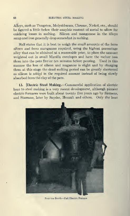
48 EIJECTRIC STEEL MAKING
Alloys, such as Tungsten, Molyddenum, Chrome, Nickel, etc., should
be figured a little below their anaylsis content of metal to allow for
oxidising losses in melting. Silicon and manganese in the alloys
scrap and iron generally drop somewhat in melting.
Hall states that it is best to weigh the small amounts of the ferro
silicon and ferro manganese required, using the highest percentage
alloy that can be obtained at a reasonable price, to place the amount
weighted out in small Manilla envelopes and have the melter toss
them into the pots five or ten minutes before pouring. Used in this
manner the loss of silicon and maganese is slight and by charging
them at this stage the dead melting period can be greatly shortened
as silicon is added in the required amount instead of being slowly
absorbed from the clay of the pots.
13. JElectric Steel Making.—Commercial application of electric
heat to steel making is a very recent development, although pioneer
electric furnaces were built about twenty five years ago by Siemens,
and Stassano, later by Snyder, Herault and others. Only the heat
Four ton Booth—Hall Eleetric Furnace

ElXCnUC FURNACE 40
energ;>' of electricity is uaed in steel making. No electrolytic action
lis required. Accordingly, either direct or alternating current maybe employed. As three phaw alternating current costs less to trans-
mit than single phase or direct current it is usual to transmit the power
in three phase form and if desired to change the three phase to single
phase or direct at the point where the current is to l)e utilized. Touse three phase current directly in the steel furnace requires three
electrodes.
The furnace charge is similar to that in the Open Hearth process,
consisting of pig, ore and scrap. The pig supplies carbon. Cast
iron scrap or carbon in the form of charcoal can be substituted for
the pig iron. The ore furnishes oxygen. Mill scale or a blast of
air can be used as an alternate supply of oxygen. Mill scrap, the
cheapest material from which steel can be made is always added to
the charge. This is especially true because the electric furnace can
lih' melt lK)rings and turnings which work badly in the Open[earth and liossenier furnaces.
The electric furnace atmosphere can be made non-oxidizing so that
such granular material is not burned and lost in the slag. Ore is the
more expensive material for this kind of steel making. Not only does
it cost more per pound of contained iron but it requires three times as
much electric energy to make steel from ore as from scrap.
The materials charge<l carry with them various forms of impurities,
the linings of the furnace melt in pots and drop into the charge. This
with the constituents of the metal, such as silicon, and maganese
combined with sulphur, oxygen, and phosphorus, form insoluable
compounds in the form of slag. To bring the slag to the proper
mechanical consistency fluxes are added, either silica or lime in
powder or granular form. The amount is relatively small, the total
slag generally weighing less than tw<>nfy p<'rrf>nt of ihr weight of
the metal.
Mechanically, an electric furnace is operated the same as an Open
Hearth furnace. As the electric furnace works faster the furnaces
are smaller in holding capacity for a given tonnage output.
Chemically, an electric fumac(> is the same as an Open Hearth,
except the oxidizing influences of the gas flame are abeent. Thepassage of current through the bath sets up movements in the metal
which serve to mix it and render it more uniform.
Higher temperatun* can be obtained at reasonable cost with the
iikK^c furnace than with the fuel steel furnace. To these high

50 , GRAY IRON CASTINGS
temperatures is attributed the higher quaUty of the metal. The
hotter slag separates more completely from the metal and the desired
reactions are carried further toward completion in the time available
for the heat. The result is a higher tensile strength for the same
anaylsis and a higher value for the elastic limit and yield point of the
metal.
When first introduced, electric steel was made at a high cost.
Gradually the furnaces have become more efficient and simpler.
Even, at the first, the eost of electric steel was said to be somewhat
lower than Crucible steel for the same tonnage output. Recently
such furnaces have been built in sizes that compare in output with
the larger commercial sized Open Hearth furnaces. The low operat-
ing cost of the electric furnace together with the high quality of the
product, renders probable a change toward electric steel making in
the coming decade similar to that which took place in the last decade
from the Bessemer converter to the Open Hearth. Where good ore
and ample water power is available, at low cost, we may look for
steel centers in the future where the scarcity of coal today has pre-
vented commercial development of the steel industry by older
methods.
14. Gray Iron Castings: Iron castings may be soft enough to
be machined with greatest ease or chilled as hard as glass. In
physical structure they may show a fracture from silver white to
gray black. This wide variation is characteristics depends on the
amount and condition of the carbon content. Roughly this will run
from 23^ to 4 percent and may be either in a combined form as in
the white glass hard iron for the one extreme or almost entirely un-
combined in the form of graphite as a dead gray iron at the other
extreme. Between these two limits there may be any combination.
This relation depends on the percentage of other elements, more
particularly silicon and the rate of cooling from the molten state, a
function of the thickness of section and the temperature of the metal
at the time it is poured to a somewhat less degree.
In the absence of silicon, the carbon present remains in the com-
bined form. Hence, commencing with no silicon with dead white
and hard iron, there is a regular progression of fractures growing
grayer and grayer until at three percent silicon the iron is dead gray
and soft. Sudden cooling in a measure prevents this action of silicon,
a relation taken advantage of when making chilled rolls, car wheels,
crusher jaws, etc.
8BMI STEEL 51
By securing the proper silicon percentage and the application of
iron face moulds, it is possible to get a fairly exact thickness of hard
white metal with a soft machinable background.
Manganese is another element always found in cast iron. Fk^low
'One percent it has but little effect on the character of the casting.
Above this it commences to hold the car)x)n in the combine<l form.
Below one half percent manganese oxidation troubles are liable to
be encountered with consecjuent damage to the casting.
A phosphorus content around one percent secures the fluidity
nece88ar>' for stove plate and ornamental castings. For the regular
run of work, this element should not exceed three quarters ix»rcent
and for special work it may have to be quite low as in gear castings
and the like.
Sulphur is an objectionable and undesirable element in ever>'
way for it hardens the casting, making tooling difficult and at the
^same time weakens it. It is unfortunately always added to a greater
or less proportion in cupola melting owing to the proportion of scrap
necessarily carried in the daily heats.
From chemical consideration cast iron might be rated as a steel
corresponding to the combined carbon present with its graphite con-
tent in mechanical athnixture.
A cast iron with .25 percent combined carl)on, 3.^ percent graphite
might be looketl upon as a .25 percent carbon steel with .so muchfinely divided lubricating graphite within the structure that machin-
ing becomes easy and no oil will be required. With .80 percent
combined carbon the material correspontls approximately to tool
steel in hardness and difficulty of machining.
Dr. Moldenky draws the interesting detluction from this relation
that steel additions now so generally used in admixture with the
foundary pig represent a reduction in the total carbon with the
proper silicon content adjusted so that the combined carbon remains
unchangeti with much less graphite within the structure. The re-
sulting metal remains machinable to almost the same extent as
ordinary cast iron but is much stronger as then» is less graphite inter-
spercetl in its structure reducing its effective cross section and
strength. The product with such admixture of structural steel scrap
iscalletlSEMUSTEKL.
A verj* soft, yet serviceable cast iron may run as low in tensile
strength as I2,00() pounds per square inch. Piston rings for auto-
mobiles are made so soft that all the wear is taken over bv them while

52 TEMPER
again chilled cast grinding muUers high in total carbon are excelled
only by manganese steel castings in point of durability.
The lack of homogeneity of cast iron makes tensile tests somewhat
uncertain unless considerable care is given the alignment of the
specimen in the testing machine. The transverse test is almost uni-
versally used, the standard test bar being IJ^" round cast upright in
a dry sand mould. This bar resting on supports 12 inches apart
should carry 2,200 pounds central load for machine castings and the
like. If some steel has been added, as high carrying capacity as
3,500 pounds centrally applied load will be exhibited.
Compared with steel, gray cast iron is stronger under compression
than mild steel but its tensile resistance is only half to one third as
great. Its fracture is without material elongation and may be
regarded as brittle and unsuited to withstand shock. Hence, a large
margin of safety must be allowed where moving parts of machines
are made of this material. Its lower cost when compared with steel
permits its use in generous proportions.
The phenomena of shrinkage of cast iron must be given attention
both in pattern making and design. It causes difficulty in securing
sound castings where heavy and light sections join. Thus, the
brackets of cast iron columns should not be made heavier than the
shell of the column. The shrinkage of white iron castings is about
double that for gray iron, the latter being }/^" to the foot while white
iron contracts about }/i inch to the foot in cooling.
Combined carbon at high temperature causes an average increase
of 100 percent in the shrinkage or contraction of the metal in cooling
and as this represents the average or total shrinkage at all tempera-
tures we may conclude from the small difference in coefficient of
expansion at ordinary temperature that at higher temperatures this
shrinkage may be three to four fold as great with the combined
carbon as it is with the carbon in a graphite state or entirely elimin-
ated.
The interesting phenomena observed in the tumbling barrel throws
a strong light on the relief of shrinkage strain by shock or range of
stress from tension to compression for standard test bars after being
rumbled in the tumbling barrel are found to be greatly strengthened
by the process—so much so that they are not comparable with the
cast metal in the work they are intended to represent.
15. Temper.—Temper is the term employed by the steel manu-
facturers to indicate the proportion of carbon contained in the steel,
(usually a Crucible product.)

TEMPERING 53
Razor Temper.—l}^ percent carbon. When properly treated it
will do twice the work of ordinary tool steel in dressing chilled rolls.-
Saw File Temper.—1^ percent carbon. This should not be
heated above a cherry red.
Tool and Drill Temper.— 1^ percent carbon.
Spindle Temper.—1^ percent carbon.
Chisel Temjier.— 1 percent carbon. This is well adapted for tools
when the unhartlencd part must bear the blow of the hammer and
where a hard cutting edge is required as for cold chisel.
Set Temper.—]/^ percent carlwn.
Die Temper.—^ percent carbon.
The two last may be welded by the mechanic accustomed to weld
cast steel. The carbon content may be roughly indicated by the
terras low temper, medium temper and high temper steel.
Many manufacturers of tool and high speed steel, differentiate
the temper by letters or numerals in their catalogs showing not only
the classification but the purpose for which the steel is best fitted.
The term temper indicating the uniount of carl>on is to lx» differ-
entiated sharply from tempering or heat treatment of the tool
dressor and manufacture'.
16. Heat Treatment.—The effects of thermal change upon steel
varies greatly with its carbon content and the precise nature of the
treatment. Any steel except alloys of silicon, tungsten, etc., may be
SOFTENED OR ANNEALED by raising to a read heat and allow-
ing it to be cooled verj' slowly. When thus annealed, though the
carbon content is high, it is relatively soft and may be cut or filed
and turned in a lathe.
HARDENING OR TEMPERING tool steel consist* of two
steps: The finished tool is heate<l to a bright red, care being taken to
have the heat extend back some distance from the e<lge. The cutting
edge is then immerse<l in water to a slight depth and kept there until
it has cooIihI sufficiently to remain wet when withdrawn. By this
treatment the material in the vicinity of the cutting o<lge has l)een
rendered exceedingly hard but too brittle for service.
The excessive hardness is re<luco<l, and the necessary toughness
secured by "tempering" which consists <)f brightening the metal near
the cutting cilge by rubbing on emery or carl)on»nihnn and watching
the cleaned area while the heat from the uncjuenched jmrt extends
toward the cutting edge. The oxidation of this brightened surface

54 TEMPERING
as the edge becomes hotter and hotter from conduction causes a play
of color to become visible which serves as an index of the tempera-
ture. The colors run from the hot portion of the tool toward the edge
in the following order: Pale yellow, straw yellow, brownish yellow,
light purple, dark purple, pale blue and dark blue. When the proper
color reaches the cutting edge the piece is again quenched and the
tempering is complete.
Turning tools, planer tools, and hammer faces are tempered at
pale yellow (430°F.).
Penknives, razors and wood tools, dies, punches, drills, etc., staw
yellow (450°F.).
Chisels, wood working tools, plane irons, brown yellow (490°F.)
Light purple, augurs, surgical instruments, cold chisels, etc.
(520°F.).
Dark purple, (550°F.) axes, hack saws, springs and wood saws.
17. The Effect of Quenching Soft Steel is illustrated by an
experiment by Campbell, given in the following table
:
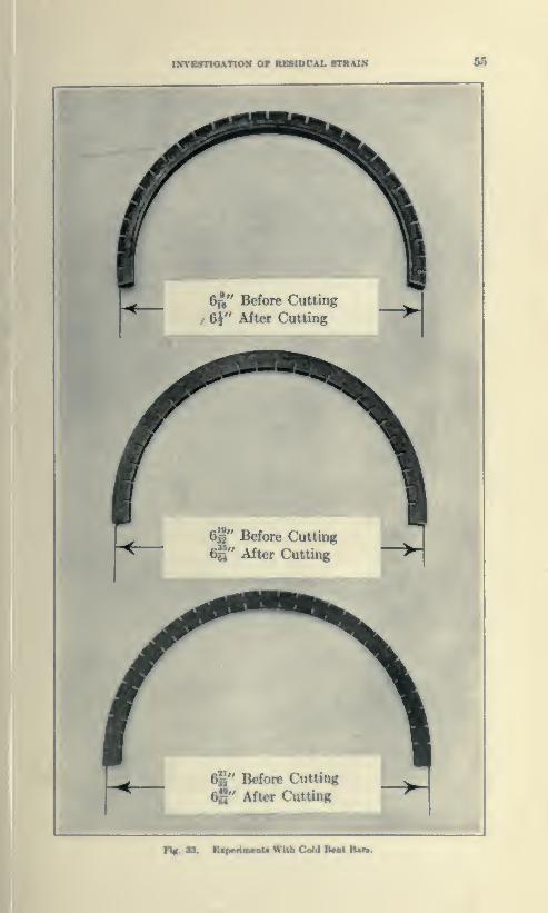
ufYcanoAiioic or bsbidital tnunr A5
ef," Before Cutting
6§" After OittinK
^" After Cutfinir
S" Before Cutting
\" After CuUing
F%.tt. »i|iiilB»tiWWlCaid

66 RESIDUAL STRAIN
quired for the purpose for which the tool is to be used. The increased
tensile resistance is attained by the reduction of ductility. Forexample, the very soft specimen, if its ultimate tensile resistance be
figured on the greatly reduced area of fracture does not differ greatly
from that of the hard steel specimens.
Thus with the reduction in area in the above table of a soft steel
specimen of 70 percent, the unit breaking strength per square inch
on the reduced area would be between 150,000, and 160,000 pounds
per square inch, corresponding to the breaking strength of a steel of
high carbon content under Campbell's rule that does not reduce
materially in area at fracture.
18. Over Strain and Cold Working.—The softer grades of steel
are punched, sheared and bent cold, and the general effect of such
cold working upon the material is here to be considered.
Because the softer grades of steel are ductile, or plastic under over
stress, they may take a set in one direction or in one portion unac-
companied by corresponding set in another portion. Equilibrium
results from a more or less complex state of internal strain, and the
elastic conduct of the material thereafter is represented by this state
of strain superposed upon the elastic state resulting from the load
applied. Its deportment is then said to be aeloltropic or different in
different directions.
This characteristic of soft steel is encountered when a key wayis cut in a piece of cold rolled shafting. The surface has been sym-
metrically strained by the work expended upon it by cold rolling.
This internal state of stress is thrown out of equilibrium upon removal
of the metal in the key way and the shaft then undergoes a slight
axial curvature. The following experiment discloses a nature of
these reactions.
Cut several pieces from the same ^ inch square mild steel bar,
and bend cold to 6-inch diameter as shown in the accompanying
figure, so that the spread of the ends is about six inches. Measure
out to out spread carefully and record the same. Then score with a
saw kerfs about % inch spacing on the outside and to the depth of
^ inch. The distance between the ends of the curved bar will
elastically decrease Ath of an inch by this process. A similar speci-
men bent in the same way, sawing kerfs on the inside of the bend
will indicate a change of curvature A th of an inch in the same direc-
tion. Another similar specimen treated after bending by sawing
kerfs on the outside and inside }/^ inch deep only and similar spacing

PBRMANXNT STRAIN 57
produces a change in curvature in the opposite direction from that
of the preceding experiments amounting to i^thH inch spread; a
lecrease in curvature instead of an increase showing a reaction of
'idastic strain antipodal to that of the residual strain. The ela.stic
strain being reverse in kind and character to that of the residual
strain its effect is to straighten the bar out and reduce its curvature,
whereas the residual strain tends to increase its curvature when
thrown out of equilibrium. Permanent strain, therefore, is a state
of internal stress in equiiil)riuni from which no change in shape results
unless this state of equilibrium is disturbed by the action of forces
which supply energy from without, or change the area of the re-
sisting section.
Energ>' changing tj^e internal state of equilibrium may be intro-
duced as follows:
1. By chan(^ of temperature:2. By applied forces:
3. By cutting away a portion of the symetrically strained body.
Such a removal or cutting away of symmetrical portions of an
over-strained elastical material permits the permanent strains thrown
out of the equilibrium to rea.ssert themselves and change the form of
the body in a manner comparable to applied external forces.
19. Aeolotropic Properties of Permanent Strain.—Steel, copper,
aluminum, etc., a« received from the rolling mills and castings lus they
come from the foundary arc inherently aeolotropic because of the
squeeze of the rolls in producing the former, and the shrinkage or
cooling stresses in the latter.
The theory of stress intensity and ehusiicity forming the basis of
design assumes their condition as Isotropic as an approximate basis
of analysis. The investigation of the magnitude of the error of such
assumption is now in order.
In the experiment with the bars bent in horse shoe form the spring
upon cutting one outer layer was in the n'verse direction of the elastic
reaction to the forces which caus<'d the j)ermanent In'nd. This
observation is in ke(>ping with tlmt of Joule, that the n»si(luul effect
of a permanent strain is a change in the position of the metal in the
Antimony Bismuth scale of thenno electric potential, in the n'verse
direction to that caused by the elastic strain which subsists as long
as the constraining force is kept applitnl.
This result may be regarded as a direct consfcjuence of Nrwton's
third law that action and reaction are equal and of op|K)site sign.
58 PERMANENT STRAIN
Applied to the case in hand, when applied force is removed and the
elastic reaction to the original configuration is prevented by set or
plastic deformation along the lines of resultant displacement, the
internal stress changes sign.
No over strain has been experienced along the lines of equi-
potential and the stress there thrown out of balance is momentarily
undiminished and must be brought into equilibrium by residual
strain along the lines of displacement following the mechanical law of
equality of major and minor stress volumes upon their respective
planes of action which is' a consequence of the equality of maximumand minimum fiber stress areas treated in Art. 20, Chapter I.
Consider the case of axial tension Fig. 13, Chapter II as the
material along ec, ec' takes a plastic set which opposes elastic recovery
along eo, e'o, the latter elastic stress induces residual counter balancing
stress along ec, ec'. But, since these residual stresses of tension and
compression are in equilibrium the axes of the principal stresses of
the residual state of strain will shift to a position at 45 degrees to the
axis of the bar.
The effect of superposition of such a state of residual strain upon
an isotropic material would be to increase the Y (yield point) limit
of plastic set, reduce somewhat the value of the modulus E and the
coefficient K.
The limit of elastic stress along the equi-potential curves within
the elastic range of stress along the curves of displacement would
limit the reduction in the value of K from an isotropic state (.4142)
to .336. This is above the value of .3 of the ordinary test as it should
be when the restraint of the grips is considered, therefore we mayrationally consider the state of residual strain from rolling the limit
of plastic deformation.
The elastic unit stress along the curve of equi-potential equals
half that along the curve of displacement, hence its momentary value
at the instant of plastic yielding on a 45 degree line equals P cos. x sin
2^30' which is out of balance. Equilibrium will accordingly require
a static balance of half the stress intensity by an equal and opposite
stress at right angles, in the resultant state of residual strain. This,
with respect to elastic elongation under a further load is equivalent
to an applied force of the opposite kind. On this basis K equals .336,
F equals .37j5J, the value of E is approximately 29X(10)^ for soft
steel and 3X(10)^ for hard steel.
SUMMARY: The foregoing discussion of the properties of
materials is of necessity meager, and logically limited to those phases

SIMMARY «
rebtcnl to their ela^iiiiiy ami resistance. An attempt has
_been made to present the outstanding facts r^^rding conditions,
to toughness and dependability of timber in respect to age
*Mid condition of cutting and to explain the reason for and necessity
joi limitation of impurities in steel and the outstanding phases of its
mfacture, heat treatment and condition after over strain. These
tttera are commonly not understood at all by the graduate of our
civil engineering .soh(x>ls.
The short discussion of steel here presented may best be supple-
nimteti by referring the student to The A. B. C. of Iron and Steel,
Ptriton PublLshing Company, Cleveland. Howe's Metallurgy' of
Steel and Manufacture and Properties of Structural Steel by H. H.
Campbell.
A fairly complete, treatment of concrete, discussion of aggregate,
mixture, handling at different temperatures, shrinkage, strains, etc.,
will be found in Concrete Steel Construction, by Exldy and Turner.
60
CHAPTER V.
INVESTIGATION OF THE RANGE OF IMPERFECT ELASTICITYWITHIN THE YIELD POINT VALUE OF STEEL,ENDURANCE OR FATIGUE TESTS, AND THE
WORK OF RUPTURE.
1. Where an elastic body is subjected to stress, and the strains
it undergoes do not pass beyond the hmits of the true elasticity of the
materials, the work expended in straining the body is restored by its
reaction as the stress is removed. But when the strains exceed those
limits, work is expended upon the material that is not so restored.
The energy so expended beyond the elastic resilience of the body is
dissipated through the evolution of heat, and the body is not able
to restore fully the energy imparted to it by work performed beyond
the true elastic limits.
This work done upon the material tends to change its properties.
When a piece of mild steel is gradually loaded in simple tension to
between five eights and two thirds of its ultimate strength, a point
is reached where a large plastic deformation occurs with very little
increase in the applied load. This is called the yield point, or com-
mercial elastic limit, and is determined by the drop of the beam in
testing. When the load is carried to a point somewhat beyond this
primitive yield point and the load is then removed, on subsequent
testing of the same piece it will be found to have developed a newyield point at a somewhat higher load than that previously found,
while the limit of proportionality between stress and strain has at the
same time been reduced below the value previously found. If,
after being considerably over strained the specimen be allowed to
rest for a certain interval of time before being reloaded, it then
exhibits greater hardness than does a similar specimen similarly
treated and reloaded immediately. Its yield point is further raised
by such a period of rest and its elongation at fracture is reduced.
The apparent limit of proportionality rises during this period of
rest from that position to which it has been lowered by the over
strain. When a piece of steel is strained beyond the limit of true
proportionality and within the yield point value, a temporary strain
is observed after the removal of the load. The disappearance of the
temporary strain which occurs by a slow creeping back of the material

ELASTIC AFTXR WORKING 61
called ehustie after wnrkinjf and the 1:ik or slow increase of de-
formation under stns.-^ is called hy.stntsis.
2. Elastic After Working.—The German writers refer to this
phenomena as "elastische Nachwirkung," which mi^ht t>c translated
^"elastic reaction" if the word reaction were not already used in a
fcrent sense. The phenomena is more readily observed by twist-
ing a fine wire suspended from a fixed support . having a small mirror
attached to the lower end, the position of which can be observed in the
usual way by means of a telescope and scale. If the lower end of the
wire is twisted through an angle not too great and then left to itself,
the mirror makes oscillations, the extent of which may lx» read off
on the scale. These oscillations decay more rapidly than as if the
only retarding force were the resistance of the air, showing that the
force of torsion in the wire must be greater when the twist is increased
than when it is diminishing.
"If we begin by keeping the wire twisted (at not too great or too
small an angle) say for a minute or an hour, and then leave it to itself,
we find that the point of temporary equilibrium is displaced in the
direction of twisting, and that this displacement is greater the longer
the wire has been kept twisted. But this displacement of the point
of equilibrium is not of the nature of a permanent set, for the wire,
if left to itself, creeps back towards its original position, but always
slower and slower. This slow motion has lieen observed by the
writer going on for more than a week, and he also found that if
the wire was set in vibration the motion of the point of equilibrium
was more rapid than when the wire was not in vibration.
We may produce a very complicated series of motions of the
lower end of the wire by previously subjecting the wire to a series of
twists. For instance, we may first twist it in the positive direction,
and keep it twisted for a day, then in the negative direction for an
hour, and then in the positive direction for a minute. When the
wire is left to it-, if. the displacement, at first p<»Hti\r. l.c,,.iiies
negative in a few seconds, and this negative displaceiiunt mcrea.s<»s
for some time. It then ditninishes, and the displacement U'comes
positive and lasts a longer time till it too fin:ill\ dir- :iu:i\ ' (Max-
well. EInc. Brit. Constitution of B(Klii«s.)
The phenomena alxjve descrilwil represents an angle of dis-
tortion greater than the true elastic limit but less than the yield
point of the metal.
Kelvin Ims treated this phenomena as the. "viscosity" of elastic
soli(i>

62 FATIGUE
In the preceding discussion this so called viscosity has been
explained by the fact that there must be transferred from the internal
heat energy of the material to potential energy of strain double the
mechanical work in equivalent heat units to that expended in pro-
ducing the strain. This should be obvious since the effect upon the
heat vibration of the particles composing a body is a function of the
final state of deformation and independent of intermediate states,
whereas the static external work performed is per contra a function
of the intermediate states rather than the final state which is opposed
and held in equilibrium by the internal strain. In other words, the
external mechanical work is half the product of the final force multi-
plied by the strain or displacement. The thermo dynamic effect is
a function solely of the total displacement, hence twice the mechanical
work causing the given displacement.
2. Apparent Elastic Fatigue. Experiments on the torsional
vibration of wires detailed by Kelvin in his article on Elasticity in
the Encyclopedia Britannica, indicate elastic fatigue for a con-
siderable range of stresses through which the experiments were
conducted, this range being within the limit of elasticity of shape.
The experiments were as follows:
About April 26th, two equal and similar lead weights or vibrators
were hung up by equal and similar copper wires, the upper and lower
ends of the two wires being similarly fixed by soldering. Wire No.
2 was kept vibrating as continuously as possible from day to day,
and the other kept at rest except when vibrated once a day in an
experiment to test the comparative vicosity of the wires, but no
exact comparison was made until May 15. Then No. 1 in 97 vibra-
tions subsided from an initial range of 20 to a range of 10, while No,
2 gave the same subsidence in 98 vibrations. During the greater
part of May 16 and 17, No. 2, was kept vibrating and No. 1 quiet
and experiments made, with the result that No. 1 subsided from an
initial range of 20 to 10 in 98 to 99 vibrations of 2.4 seconds each,
while No. 2 gave the same subsidence in from 57 to 60 vibrations of
2.4 seconds each.
It was supposed from these experiments that true elastic fatigue
occurred for all stresses within the limit of elasticity of shape until
a similar and more extensive series of experiments conducted by H.
Dissipation of energy by heat in the non-reversible cycle of imperfectly
elastic strain beyond the tfue limits of elasticy is the explanatiion of the apparentfatique above noted.

NATIRAL ELASTIA LIMITS 68
Thomlinson (Phil. Trans. Royal Soc. 1886) showed that no such
fatigue of elasticity is felt in steel, iron or copper pro\ided the stress
does not exceed a certain well defined limit.
4. Variation in Yield Point Values of Mild Steel.—In Art. 1,
it is noted that by straining the material alx>ve its primitive yield
point, releasing the load and reapplying it a yield point or drop
of the l)eam will be observetl at a somewhat higher value. Again,
when a liar of steel is loaded a number of times alternately in tension
and compression to a point a little beyond the primitive yield point
values in tension and compression, these values are thereby both
reduced to about .6 their original values called by Bauschinger
the NATURAL EL.\STIC LIMITS of the material.
When the material is repeatedly strained in tension from «ero
to a value above the natural elastic limit in tension but within the
yield point, the yield point value in tensoin is raised by such treat-
ment and in like manner when similar stresses above these natural
elastic limits but within the yield point values, are applied alternately
from tension to compression, the primitive yield point value in tension
is lowered. This phenomena raises the question whether the tem-
porarj' strain which accounts for the elastic after working is of the
same nature as that produced by a permanent set and what the
limits of its accunmlation may be under repeated stress in working
of the material without giving it an opportunity to recover by elastic
after working Ix'tween consecutive loadings.
These questions would seemingly be more readily investigated
from consideration of the thermal stress curves presented by the
material under load.
Fig A, shows typical- thermal stress curves for soft and mediumsteel in tension and compression, given by the author in Trans.
Am. Soc. C. E. 1902.
It will Ik* notice<l that in tension that the soft steel grows regularly
cooler until al)out five eights the yield point value is reache<l when the
heat of imperfwtly elastir deformation causes the curve to depart
from the straight line rt^lation until the yield point is reache<l whenthere is a sudden evolution of heat. In Uke manner, under compres-
sion the straight line relation is maintained until baout five eighths
the yield point value is reached, then a similar phenomena m-curs.
The identity of cause, i.e., thermal effei't would ijulirate identity
of result. In other words, within the range of imiKTfert elasticity
within the yield point under repeated working of the material lieyond

64 THERMAL STRESS CURVES
its natural elastic limits, an accumulation of residual strain occurs
with each repetition of the applied load even though no apparent
set or plastic deformation is noticeable. As the apparent yield point
is gradually raised by such treatment, the range of stress may be
gradually increased to a higher and higher amount until the ultimate
resistance of the material is reached without noticeable plastic de-
?0
PATIGUB KXPBUMSNTB 66
tion whether change in the yield point value is a phenomena of residual
strain or change in structure. It has been found impossible to dis>
ijcover microscopically a change in the nature of the material which
Hias undergone a sufficient number of repetitions above the natural
elasUc limits of the material to nearly wear it out or cause it to ap-
proach the point of rupture.
5. Woehter Experiments.—The behavior of iron and steel under
flucutating or repeated stresses was the subject of long research by
Woehler and later by Bauschinger. The result of these experiments
are claimed to show:
/. That resistance to fracture under stresses fluctuating within
certain limits depend upon the difference between the maximum and
minimuni applied stresses rather than upon the maxim uin si rcss alone.
f. And that reversed stresses, tensile and compressive, much below
the static breaking stress, are sufficient to cause fracture if repeated
a great number of times.
Experiments upon axle iron made by the Phoenix Company,
having an ultimate strength in tension of 23 ton.s with an (longation
of about 20 percent, gave limiting maximum strcKst\s under limited
ranges as follows:
Kind of Repeated IxMd

66 FIDLER'S THEORY
yield point, and since whenever the primitive yield point is exceeded
a large deformation results, the manner in which these repeated
stresses were applied is of interest.
To avoid the large deformation which would have been produced
when the primitive yield point is exceeded, the stresses first applied
in these experiments, were less than the primitive yield point and this
point was thus gradually raised until its ultimate position was above
the maximum stress considered in the range noted as the limiting
range.
In a practical structure the conditions of loading are not such as
to raise the yield point value of the material and so increase its
resistance, as was done in these experiments.
Consequently, the limiting ranges of intensity of stress which the
practical structure can withstand cannot be deduced from
experimental results where such artificial assistance is extended to
the resistance of the material.
A dynamic theory of fatigue has been propounded by T. C. Fidler,
in which the breaking load "a" is derived from the applied stress "t"
as follows:
1
.
Steady load no variation a = t.
2. Load varying from O to t — — a = u = t/2.
3. Load varying from + T to —T a =u =t/3.
As further experiments have shown that the number of repetitions
of stress beyond Wohler's limiting ranges required to produce rupture
is substantially constant whether the speed of application of the
fluctuating stresses is decreased to half that in Wohler's work or
doubled. Moreover, while the effect of a load imposed instanta-
neously and without shock, causes momentarily twice the effect of an
equal gradually applied load in producing deflection and strain, it is
illogical to suppose such a relation could possibly exist with the time
of application extended thru the interval of fifteen seconds as was the
rate of application of repeated loads in Wohler's experiments. More-
over, if the method of computation be applied to the loading within
the limiting ranges of tension to compression it at once appears that
the computed stresses have exceeded the yield point by 50 to 60 per-
cent without raising it at all. These two difficulties render the theory
wholly untenable.
The micro flaw theory of fatigue advanced in Johnson's "Materials
of Construction," is equally untenable in its failure to account for
observed phenomena. Thus, the elastic fatigue in Thompson's

THEORY OF REBIDUAL STRAIN «7
experiments depending upon the immediately previous molecular
condition whether of quiescence or recurring changes of shape
cannot be accounted for by micro flaws which are necessarily i)cr-
i^maoent and not temporary.
As the originators and advocates of the fatigue formulae of pro-
portioning agree that if it be established that Wohler's results are
accounted for by the effects of stress beyond the true limits of elasti-
city they have no relation to the logical determination of working
stresses, this matter will now be considered from the standpoint of
the three determinants of ideal elasticity, to-wit
:
1. Proportionality of temperature change to the ioadappiied:2. Proportionality of elastic elongAtkm to the ^ppliea stieas or
load: ^3. The revenible ^^eie of niechani<^ work during k)ading and
No bar of sound metal has ever been broken by Wohlij s tnatmentunder ranges of stress of one kind or of both kinds, i.e., from tension
to compression within the thermal limits of proportionality.
Per contra range of stress from tension to compression within the
natural elastic limits was found by Bauschinger to improve the metal
in elasticity, tenacity, and ductility instead of injuring it.
The radical improvement in the strength of cast test bars and the
suggestion that they shall not be rumble<l if their mo<Iulu8 of rupture
be taken to represent the average condition of the casting, is a striking
confirmation of the beneficial effect of stress ranging from tension to
compression in reducing and eliminating residual states of stress
arising from rolling or shrinkage in cooling.
The theorj' of residual strain shows that the range of stress of one
kind is not as efficient in eliminating residual strain as range of stress
from tension to compression. Where the range is from tension to
compression extending e(|ually alwve the natural elastic limits for
tension and compression the reaction of the accumulation of residual
strain is neutralized because of the opposite signs of its constitutents
accompanied by increased internal disturbance and more rapid
approach to rupture under repeated stress. Where the limiting range
was tension from— 10 to —21 tons the systematic work ujxm the
qiecimen has efTecte<l an accumubtion of approximately +9.5 tons
residual strain which added to the primitive yield (xiint value of 12
tons would give a maximum resistance of 21.5 tons without pla.*<tic
deformation. In other words, the effect of a tensile stress of—21 tons
OD a bar under a state of residual tension of +9.5 tons or more could

68 RUPTURE
not cause plastic deformation in a specimen whose yield point is 12
tons; since the algebraic sum of—21 +9.5 is but—11.5 therefore less
than the yield point of the bar.
The fact that rupture of ductile metal under Wohler's treatment
takes place without plastic elongation has been in the past erroneously
regarded as in some way indicating or establishing the proposition
that all ranges of stress without shock tend to deteriorate or injure
sound metal.
6. Work of Rupture.*—The law of conservation of energy in-
dicates that the same amount of energy must be expended to produce
rupture of the same cross section of a given kind of material whether
it is expanded in small quantities at different times or at one time in a
single application.
Since no portion of the work of rupture can be stored within the
metal, it must be transformed into heat readily measured by thermo
electric means. Such methods of investigation treated by the writer
in Trans. Am. Soc. C. E., August 1902, furnish a very precise and
sensitive method of determining directly the true elastic limit of the
metal. The deviation of the thermal stress curve from linear pro-
portionality before the yield point is reached, represents the mech-
anical work expended in permanently changing the state of strain in
the structure of the metal.
Where a bar of steel is ruptured by a single application of load
gradually increasing from zero to its ultimate limit resistance, but a
small portion of the deformation is elastic, viz., that part which occurs
before the yield point is exceeded. Permanent stretching then com-
mences and continues until the bar if mild steel may have elongated
twenty percent of its original length. The mean stress causing plastic
deformation would be a mean between the yield point and its ultimate
resistance or about 50,000 pounds per square inch, consequently the
work absorbed per cubic unit of metal before reaching the point of
incipient rupture would be 50,000 X .2 or 10,000 inch pounds of
work disregarding the elastic work which is relatively negligible.
Now 10,000 inch pounds of work by Joule's equivalent equals 1.07
times the heat required to raise a pound of water one degree F.
But this amount of heat is sufficient to raise the temperature of the
bar 33 degrees F an amount readily noticed by the touch or feehng of
the piece.
When rupture occurs accompanied by nearly negligible ultimate
deformation as in endurance tests under repeated stresses of intensity

BHBAB UllSB •0
lower than the ultimate carr>'inK strength of the material there appears
no g^ood reason to suppone that the total eneno' transfonned into
;heat in small amounta under succesBive repetitions of the load in
[endurance testa, is any less than where thui deformation im as large
as it is in the case of a single load which develops the maximumcarrying strength of the specimen.
In case of hard steel, since the natural elastic limit is higher the
limiting range of fluctuation stress from tension to compression is
higher than for soft steel.
But the t'litluiainr of tlic hanitr steel beyoml these limits is muchkss than that exhibited by softer metal for two reasons:
/. More heat is geiierated in hard steel when the natural elastic
limits are exceeded than is the case in the soft steel specimen; hence
more work on the structure with each repetition.
2. The total work of rupture is less because the ducility and
hence elongation when tested in the usual way is less than for softer
steel.
These dtMluctions from the work t)f rupture and thermal curves
are fully confimietl by the experiments of Wohler and Bausc-hinger.
7. Shear Lines.— If the side of a flat bar of soft steel \>q polished
and then strained up to the yield point diagonal markings appear on
the polished surface, calleil shear lines, as shown in Fig. 16.
Showii« SbMT LiBM DarclopMl ia TrnmOm T«t «f StMl B«r Biryoad Ykld Poiat.
Their direction differs somewhat from 45** determined as follows
from the principles established in Chapter I. The plane of incipient
failure from direct stress would tend to bisect the angle l)etween planes
normal to the curve of di.«placement and the lino of greatest shear.
Hence were the steel in • ftom r<<sidual strain fnmi roljini; these Unes
70 FACTOR OF IGNORANCE
would be at 56° 15' to the axis of the bar and the plane of slip normal
thereto at an angle of 33°43'. For K = .336 as the condition of the
material as received from the mill theses angles would shift 2°45'
nearer to symmetry with the axis or the marking would assume a
position of 53°30' and 36°30' to the axis respectively, as measured on
the specimen of Fig. B. As K has a different value for hard steel the
slip lines will alter their angle accordingly. Such markings have been
miscalled shear lines or stress lines (Martens) notwithstanding their
direction is a derivative only of the lines of displacement and shear.
Actual or final fracture usually takes place normal to the principal
tensile stress.
8. Practical Aspect of the So=Called Factor of Safety and
Maxima and Minima Formula of Proportioning.—Weyrauch and
Launhardt formulated an algebraic method to allow for the supposed
injurious effect of range of stress without shock. The derivation of
these formulas in principle is analogous to the old idea of a factor of
safety based upon the ultimate carrying strength of the metal in a
testing machine rather than what it can carry on the job.
To illustrate the point, a piece of mild steel has a tensile breaking
strength in a machine (which does not follow up plastic deformation
as a load acted upon by gravity would do) of say 64,000 lbs. per
square inch. If the so called factor of safety is four 64,000 lbs. divided
by four equals the working stress equals 16,000 lbs. per square inch.
Suppose the load to be suspended by a short hanger and increased
to 40,000 lbs. The yield point has then been exceeded and plastic
yielding is followed up by the free downward motion of the load.
The dynamic effect would approach that of a suddenly applied load
sufficient to rupture the hanger at five eighths of its laboratory carrying
strength under test.
The true factor was thus about two and a half instead of four.
It may be objected that there are many examples of partial bridge
failure where the post buckled out of shape without collapse or cases
where a counter after noticeably stretching did not cause failure.
The answer lies in the fact that railroad bridge loading is a rapidly
moving and fluctuating load, before the member has had time to be
deformed materially the stress has greatly decreased—a condition
vastly different from the case of static suspended load under discussion.
Likewise, in a frame or truss, large plastic deformation of a member
might so change the triangulation that here also, the yield point
rather than the testing machine ultimate, limits the margin of safety.

UNSCIENTinC FORMULAS 71
The old factor of safety soon came to be ela-swified as a factor of
ignorance bfK'ause unrelattni to the true margin of safety as it is
understood by the engineer.
The general fonn of maxim and minima formula is given in the
I8th edition of Trautwine
—
min. stress
(1) a = u (1 4- ) range of one kind
max. stress
min. stress
(2) a = u (1 ) range of both kinds
2 max. stress
u was commonly taken as 6500 for wrought iron bridges.
When there is no variiation a = 2u.
When + min. stress = — max. stress a = u/2. ,
It thus appears that the variation in the working stress was the
Uberal amount of three hundred percent of an imaginary effect.
The derivation of these formulas is as unscientific in conception as
the factor of safety, unrelated to the true margin of safety on the job
but in addition their application to have any bearing whatever upon
design assumes conceivable kind of loading impossible in practice, to-
wit, systematic and precise working of the metal to acquire that
remarkable accumulation of residual strain produced in the laboratory
alone and impossible elsewhere. The fact that heat energy of in-
elastic deformation can be measured on all ranges of stress higher
than the natural limits of elasticity bars their consideration from
rational practice in design.
These formulas give rise to unbalanced dLstribution, to efforts to
economize by using dangerously high working stresses where the range
is small and to excessive waste when the range of stress from tension
to compression would tend to improve rather than injure the material.
Such formulas arc being gradually relegated to the junk heap by
accumulated exfx»rience. Neverth<'less, they arc still taught the
student of inachine design as though in some manner they might l>e
of assistance in proportioning machine parts subject to hard usage
and repeated shock, in place of practical ol^servance and study of
results of service of similar parts under similar or analogous conditions
and proportioning in thc> light of known facts rather than by algebraic
formulas wholly inapplicable thru lack of analog>' to conditions they
were intended to n'f)resent and the erromnius and unscientific con-
ceptions upon which they an» founde<l. They may therefon» be dis-
missed as useless; prmluctive of confusion and wast« rather than
rationally balancetl d(>sign.
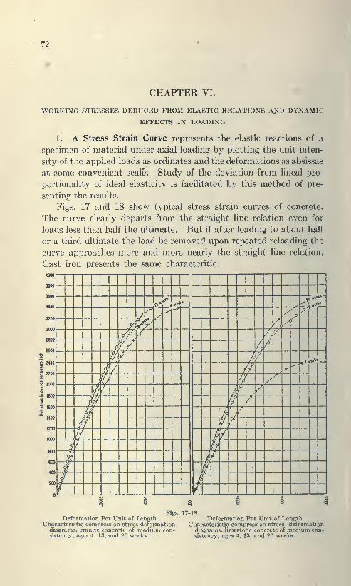
72
CHAPTER VI.
WORKING STRESSES DEDUCED FROM ELASTIC RELATIONS A^D DYNAMIC
EFFECTS IN LOADING
1. A Stress Strain Curve represents the elastic reactions of a
specimen of material under axial loading by plotting the unit inten-
sity of the applied loads as ordinates and the deformations as absissas
at some convenient scale. Study of the deviation from lineal pro-
portionality of ideal elasticity is facilitated by this method of pre-
senting the results.
Figs. 17 and 18 show typical stress strain curves of concrete.
The curve clearly departs from the straight line relation even for
loads less than half the ultimate. But if after loading to about half
or a third ultimate the load be removed upon repeated reloading the
curve approaches more and more nearly the straight line relation.
Cast iron presents the same characteritic.
4000

STRESS gTBAiN CCByn 73
When steel is tested in commercial work, the weight is run out
on the scale beam as the load is applied so that the beam floats or
swings free. The strain increases substantially as the applied load
to half the ultimate resistance; then at slightly more rapid rate to
about five eights of the ultimate resistance when a sudden plastic
yielding occurs and the scale beam drops. This is the primitive
yield point of the material, and the commercial elastic limit as it^is
unscientifically termed.
Pig. m
Mild steels carbon .20 to .40 are tough and ductile, stretching
from 28% for .20 C to 18 to 20% for C - .40.
An illustrative diagram exhibiting the typical deportment of
hard and Hoft steel, tiinlHT, wmught iron and cast iron utuier tension
and compn>sHion and the elongation or shortening l)efort« failure is
presented in Fig. 19,
Fig. 19 shows the stress strain curve of a cast iron s|)ecimen,
lacking in the straight line proportionality of strain to the applied

74 AEOLOTROPIC PROPERTIES
load presented by the structural steel specimen because of shrink-
age stresses in cooling. When such a specimen is stressed to three
eights its ultimate resistance and the load removed and the process
repeated a few times the initial curvature tends to disappear and to
approach more and more closely to a straight line relation.
Stress strain curves of concrete in compression exhibit like charac-
teristics indicating that under initial loads in general slight set or
permanent strain occurs. The material tending to become more
and more perfectly elastic as the material is loaded and unloaded a
number of times.
This phenomena in cast iron as shown by the increase in th^
modulus of rupture by rumbling the specimens. The initial appli-
cation of load upon a specimen of rolled steel or wrought iron also
will present noticeable irregularities under precise methods of testing,
indicating the presence of permanent strain from the quenching effect
upon the hot metal of the water for cooling the rolls.
The residual strain from the stretch and squeeze of the rolls would
not be disclosed by saw kerfs as in the case of the bent bar, since such
effects are symmetrically and uniformly distributed.
Cutting saw kerfs in a fifteen inch long ^ inch square or round
bar, half inch spacing, j^ths inch deep on either the top or bottom
of the bar as it passed thru the rolls, no noticable change in curvature
becomes apparent.
On the other hand, cutting the kerfs on one side of the bar as it
passed thru the rolls from a thirty second to a sixteenth inch in
curvature from the initial straight line form results, a measure of
the permanent strain of the quenching effects of the water cooling
the rolls. Fluctuating stresses of moderate intensity, vibration,
slight shock and the expansion and contraction of temperature
changes all tend in time to reduce or eliminate such states of per-
manent strain and improve the elasticity of the material.
Cold rolling the mild steel shell plates of a boiler sets up a state
of residual strain which is so relieved by temperature changes that
no deleterious effect is found in the subsequent deportment of the
plate.
2. Aeolotropic Modification of Naturally Isotropic Properties
in Metals.—From the discussion in Art. 1, it appears
—
(1) That the naturally isotropic characteristics of the metals
of construction are changed to aeolotropic to some extent by residual
strains of cooling and working in course of manufacture:

TaxRifo-Buurnc sklation coxiTAirr 76
{B) That in general these states of residual strain are <rf nunor
ntbor than major magnitude.
(5) That repeated stress or vibration well within the natural
limits of elastic deportment tend to eliminate this state of residual
strain with resultant improvement of the metal.
What then is this improvement in terms of numerical effect upon
the coefficients, E, K, and F? Bauschinger's work demonstrates
that E is increased numerically. The principle flrvrloped in Chapter
III that volume Is a kinetic invarient of ela.stio strain establishes the
fact that the coefficient A' for mild steel increases from .336 (the
usual value of .3 corrected for the restraint of the erip) to .4142 for
E ^true isotropy. The relation of the coefficients, 1 + A' = rr; shows
that F in terms of E decreases as K increases. But since the state
of residual strain Is a state of stable equilibrium until disturbed
by energy from without F representing rotational strain must Ix;
unaflFected numerically. Therefore when F is calculated from the
experimental values of A' and £" of the material under residual strain,
the numerical value of E when the residual strain is dissipated is at
once known because F is numerically constant, ^\^len the numerical
value of E exix>rimentally determined is 29,000,000 and A' = .336 for
a piece of soft steel, F = .378 E. When A' approaches its isotropic
value of Al42-\-,F approaches .3535 E, F being numerically constant
it appears that the isotropic value of E ia nearly 30,500,000 and that
the ultimate improvement in elasticity produced by range of strcas
within the natural elastic limits is an increase in E from 29,000,000
to an extreme value of 30,500,000. Thus the elongation under agiven pull may be reduced one twentieth and the lateral contraction
increased a corresponding amount by dissipation of residual strain
nduced by the rolling process.
3. Thermo Elastk Relation Between the Sign of the Stress andTempeniture Change in the Material a Constant—Reasoning from
cause to eflfect tension in the material should cause all elastic IxMlies
to grow cooler and compression wannei* Apparent but not actual
exceptions to the logical sequence of cauae and eflfect are presentetl byIndia rubl)er and certain materials of cellular structure. Suchmaterial as India rubljer w not unifonn but comfXNtite, e. g., pn*sent-
ing the characteristics of the rubber superposed upon the properties
of the gas or air filling the cells of the material.
If a rublx»r liand Ik* stretched the heat generated can readily
be noticed by toui huiL' 'in hand to the lips. If a weight be sua-

76 MODIFICATION OF VOLUME
pended by an elastic band and a hot poker be brought near the bandit suddenly contracts and raises the weight. Suppose the air cells
to be spherical before loading them for a very small strain; they will
become ellipsoids of approximately the same volume as the spherical
cells and the cooling effect may be measured by thermo electric
means.
For a relatively large strain, however, the cells are flattened out
and their volume reduced; hence the air or gas in the cell becomes
compressed and heated by this compression an amount far greater
THERMAL STRESS CURVESBEFORE AND AFTER OVER-STRAIN.
10 15 20
Load on bar, in 1000-lb. units.
Fig. 2)
than the cooling effect of stretching the rubber, completely over
shadowing that effect. Likewise, the expansion of the air filled
cells produces excessive lateral bulging accounting for raising the
weight when the heated poker is brought along side of the rubber.
Thus, the validity of deduction from the sequence of cause and effect
is substantiated rather than refuted when the diverse elastic re-
actions of the different parts of the composite material are given
proper consideration.

IMPACT 77
4. Relief and Accumulation of Residual Strains: Permanent
strain is relieved by range of stress within the natural limits of
elasticity but accumulates when the range of stress exceeds these
limits as shown by the thermal stress curve of a bar three days
after over strain as determined by the author is reproduced from
Trans. Am. Soc. C. E., August 1902. The irregularity of the curve
indicates the dissipation of energy in non-elastic resistance in pro-
portion to the range of stress therein agreeing with Wohler'a con-
clusion regarding the effect of stresses exceeding these limits.
5. Modification of Volume by Residual Strain.—Stokes, in his
mathematical and physical pajx^rs (1845 Vol. 1, page 75, points out
that the modulus F and the bulk modulus B are of basic importance
in theoretical work while in engineering work on the other hand E and
F are more convenient. We have reduced the kinetic and geometric
moduli of the four coefficients of elasticity E, F, K and B regarded
heretofore as partly independent, to correlated and dependent values
in which B is unity for the kinetic modulus of elastic stress in the
uniform isotropic solid. As before noted, B differs from unity for its
static value. Its modification in states of residual instead of elastic
strain will now be considered.
Cold working, such as stretching the material or compressing
it so that it bulges laterally, opens the grain and reduces the density.
Annealing on the contrary increases the density, quenching reduces
the density which is again increased from the chilled hard state by
drawing the temper and again quenching. Coefficients of expansion
are modified by these changes.
It appears that the effect of quenching is that of an extreme
condition of residual strain in which the enonnous pressure of the
chilled exterior, while perhaps closing the grain of the interior,
stretches and opens the grain of the exterior portions. Annealing,
drawing the temper to the desired point, and quenching, by relieving
the intense strain of the exterior portion, changes the properties
of the metal from brittleness to toughness, reduces the hardness
which is even then sufficient for edge tool purposes and renders the
tools reliable in that they can perform their work without breaking
under shock or jar.
An interesting field of investigation is here open, experimental
work along this line having heretofore been somewhat fragmentary.
6. Dynamic Effects.—When a load is applitnl suddenly without
bock the momentary effect of that load is to pnMlucc a deflection or

78 IMPACT FORMULAS
strain twice as great as the same load gradually applied. Accordingly,
in bridge structures the suddeness of application is provided for under
what is customarily termed impact allowance.
The additional deformation of a member under load applied with
complete suddeness over and above the static deformation depends
upon the magnitude of dead load stress on the member or it is pro-
portional to fTTT in which L = live load stress, and Z) = dead load
stress.
The proportional relation of the loading to complete suddeness
will be an inverse function of the speed of the train relative to the
length of loaded track A, which produces the maximum stress (S).
Thus, if the maximum speed is 100 feet per second, then for vertical
100vibration the impact would be approximately . „„ for complete
suddeness, considering the element of time of transmission through
the elastic ties or floor metal.
\d+l)-The approximate total vertical impact I = S
The rolling load tends to set up structural vibrations laterally
as well as vertically; consequently the total impact is the resultant
of the vertical and horizontal effects combined. In turn, the stiff-
ness of the truss articulation enters as a factor so that we may write
as a final approximate value
/ L 140 \j?^= >S I T^ , T X . , -. ^^ I for pin connected railroad bridges:
\D-\-L A+ 100/
^'=s( X . Ifor riveted railroad bridges:
Z)+L A+ lOO,
Where the range of stress is from compression to tension or vice
versa, L must overcome D of the opposite sign in reaching its value;
hence the change in stress is L+Z) for the numerator and the first
factor becomes unity, and I in per cent of S becomes
140
130 ^ .
/+ .I .^^ for riveted spans.
For double track bridges, .7 tenths the above values are sufficient.
IMPACT 79
The common forimila lor impact w that of C. C. Schnei«i«'r, now
emboiiitHl in American Uuilwav Maintenance of Way Sfiecificationa:
300/ ZZZ. q
A +300in which a« above, / = impact, 5— the computed maximum live
load stress, and As the length of loaded track a^ in iIh pn rtHiing
notation.
The dt'ticieiices in lliis formula are thu.s .stated l>y ( ). H. Ammann,Trans. Am. Soc. C. E., 1918, p. 911. It givo.v cxicssivi values for
long sfmns and ballasted bridges and insufficient values for short
stringers, on which the dynamic effect is greater than 100 percent.
A detail computation may clear up the relation of deformation
where the part is under a dead stress, D, and has suddenly imposed.
If D = 0, then the dynamic work Q = Le m which e is the elastic
deformation due to the load L. But for D>0, the piece is under anLe
initial stress D, the dynamic work Q = . ^ instead. After vibration
has ceased with the load still in place the stored energ\' which the
member can give back in raising the load during gradual unloading is
Le/2.
7. Cushioning the Impact of a Striking Body.—Special problems
of this kind are readily solved by proportioning from analogous
experience or data.
The kinetic energ>' in a moving body by mechanics is the pro<luct
of the mass times the square of the velocity or Q=(3/V')*. The
cushion effect, as for a saw mill carriage, is to stop a car weighing
four tons at a piston speed of 20 miles per hour. .\ 15'' air cushion
is found sufficient to perform this 8er\'ice.
In the Transporter Bridge at Duluth, the weight of the car
equals 120 tons; speed 4 miles per hour. The relative kinetic energy
of the traveling ferr>' car is 120X(4)»- 16X120- 1920 tons per
hour units. The kinetic energy of the saw mill carriage is 4X(20)'
in the same units»1600 similar ton unit> Tuo I") inch cushions
were provided to receive the Ferrj' car wliich ls nearly twice as
liberal a provision as is made in saw mill practice, a pr()vi.sion which
would pennit the car to run into the slip at full speed and come
to rest under ti^ lestatADce of the cushions without damaging the
structure.
8. Impact in Machines.—It is difficult and generally impossible
to determine the magnitude of the forces and the energy representing

80 WORKING STRESSES
shock which exceeds the effect of a suddenly appHed load in machines
of various classes subject to hard usage. Such machines must be
developed by experience rather than computation, by careful observa-
tion of the service which the particular part gives, increasing or
diminishing proportions as the service permits, or demands. The
original design should be based upon the best available comparison
of the endurance of the parts in analogous service.
Where the part subject to shock is able to deflect, as a spring,
then the work of flexure is capable of absorbing a large amount of
kinetic energy which direct elastic deformation of material cannot
do because of the relatively small motion which it permits within the
elastic limits of the metal.
When the service is such that the part will be stra'ned by shock
beyond the natural elastic imits of hard steel, then medium grade
ductile metal may last onger than the material with higher elastic
limits. Constant renewals and limited life of the part will result
from such a condition. Increase in size within the imits imposed by
reasonable bulk and cost may effect a practical or reasonable and
economic period of endurance.
9. Working Stresses—Steel.—The uniformity of mild steel of
good quality permits the adoption of working stresses approximately
as defined by its elastic qualities without allowing that wide margin
necessary to cover lack of uniformity and wide divergence in resistance
to tension and compression in different directions necessary when
using stone, brick and timber. The fact that mild steel has a definite
range of thermal proportionality under stress gradually applied that
within this range states of residual strain become dissipated and
relieved with corresponding improvement in tenacity as measured by
the modulus E the ductility and reduction of area at rupture, that
beyond this limit there is a range of imperfect elasticity within which
under range of stress residual strain accumulates with deleterious
effect indicates that rational design should employ stresses based
thereon.
This limit for soft steel is approximately 22,000 lbs. per square inch
and for medium steel (60,000 to 70,000 lbs. per square inch ultimate)
24,000 to 26,000 lbs. per square inch. Three-fourths of these values
may be taken for the working stress, to wit; 16,000 bis. per square
inch for soft steel and 18,000 lbs. per square inch for medium steel.
Such values allow a thirty percent variation for the limit of
inequality of stress distribution which may occur through slight

SfnUBNOTH or MAAONRY 81
sntricity of loading, 8ccondar>' stressee and sul>8idiar>' efff?ct«
led in the general analysis of predcnninant action.
Impact allowance is to be made for dynamic effect of suddenly
applied loads and the structural vibration result ini: therefrom.
Elxtreme stresses from wind pressure such as are known to occur at
rare intervals from hurricane or cyclonic stonns may safely excee<l
these values tu.my five to thirty five percent.
In disregarding .^(M-ondary stresses, goo<l practice requires if
not thorough precise investigation, at least limitation by such truss
triangulation that the dopartun* from the equilateral triangle is
not too extreme nor the proportions of depth to span length such
that relatively excessive deflection results.
STONE: In dealing with stone masonry we have wide variation
in compressive strength of the material, relatively small tensile
resistance which necessitates careful embedment of the material
that it may not crack under flexure.
The strength of the masonrj' depends on the care with which
the stone are quarried and the uniformity with which they are em-bedded or placed in the mass. The resulting stnii^th is thus a
function of the mortar fonning the bed or joints, and the stone
forming the major portion of the body.
The strength of the wall must depend on the weaker material
which is usually the mortar joint, and permissible load carrying
capacity is limited more by the mortar joint in rough work than bythe compressive resistance of the individual stones.
The strength of the mortar depends on the kind, whether ordinary
lime mortar is used or natural or Portland cement mortar employed.
Lime mortar hardens slowly, particularly in the interior of a large
mass. Natural cement or hydraulic lime is an improvement in this
respect though inferor to Portland cement.
Permissible working pressures per square foot have in practical
work been arrived at by experience rather than by invt^stigation
of the crushing strength of the stone and its characteristics in small
samples. larger blocks show relatively less resistance than the
small sample because there is more opportunity for planes uf weak-
ness due to upheaval of the material in its natural bed. With the
more general introduction of Portland cement, working values use<l
in the past with hvdruulic lime and uiaknr mortars may be logically
increased.

82 STRENGTH OF TIMBER
COMPRESSIVE STRENGTH OF MORTAR i^ INCH JOINT:Portland Cement Mortar, 3 mos. old, 1 cement 3 sand 55 tons per sq. ft.
Portland Cement Mortar, 3 mos. old, 1 cement 2 sand 70 tons per sq. ft.
Natural Cement Mortar, 3 mos. old, 1 cement 3 sand 12 tons per sq. ft.
Lime Mortar, (best) 8 to 9 tons per st. ft.
STONE WORKRubble walls, lime mortar 5 tons per sq. ft.
Rubble walls, Portland cement mortar 15 tons per sq. ft.
DIMENSION STONE SQUARED IN CEMENT MORTARSandstone and Limestone 20 tons per sq. ft.
Granite 30 to 40 tons per sq. ft.
With % in. dressed joints 60 to 80 tons per sq. ft.
Granite .' 40 tons per sq. ft.
Marble, high grade 30 to 40 tons per sq. ft.
Sandstone 25 to 35 tons per sq. ft.
In practice neither stone nor brick work should be trusted with
more than l/8th to l/12th their crushing load. Stone generally
commences to crack at about half the ultimate load. Whenthoroughly wet some sand stones loose half their strength.
See:—Tables of Crushing Strength of Granite, Lime and Sand-
stone, given in Lanza's Applied Mechanics, pp. 551-554. J. Wiley
1886. Kidder's Architect's Pocketbook. Trautwine Civil En-
gineer's Pocketbook, and American Civil Engineers Pocket Book,
Merriman.
WORKING STRENGTH OF BRICK WORK ALLOWED BYDIFFERENT BUILDING CODES
Materials
Hard burned brick in Portlandcement mortar
Hard burned brick in natural
cement mortarHard burned brick in cementand lime mortar
Hard burned brick in lime
mortarPressed brick in Portland
cement mortarPressed brick in natural
cement mortar
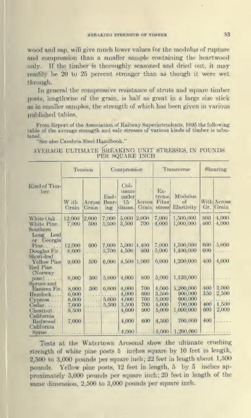
bheakinc rtres'gth or tiiibeb 8S
wood and sap, will g,i\e inui-n lower values lur the modulus of rupture
and compreseion than a smaller sample containing the heartwood
only. If the timlM>r is thoroughly seasoned and drie<l out, it mayreadily be 20 to 25 percent stronger than a.s ttioiiii:!! it were wet
through.
In general the compressive resistance of struts and square timl)er
posts, lenjjtluviM* of the grain, is half as gn»at in a hirge siw stick
as in smaller siunples, the strength of which has l>een given in various
published tables.
FromRepOTioftiieAaMKtatkm of Railway Superintendents, 18M the following
table of the avenge straigth and safe stienee of various kinds of timber is tabu-
lated.
"See also Cambria St«el Handbook."
AVEILXGE ULTIMATE BREAKING UNIT STRESSES, IN POUNDSPER SQUARE INCH
T«i8ion
Kind of Tim-ber '
\V ith
GrainAcrossGrain
Compression
End-Bear-ing
Col-umnsundo*15
diam#
Transverse
Ex-treme
Acroaa' FiberGrain! stress
Modulusof
Elasticity
Shffaring
WithGr.
\rro8BGrain
Whit«»r>nkWhito Pine
SouthcniLong Leafor GeorgiaPineDou^as Fir
.
Short-leafYeUowPineRed Pine
\
(Norway)
tee and '
Fir
Hemkick...
SSTChestnutCalif r—R.
Cftli:-:.—Sprue. .
12,0007.(K)0
12,0008,000
9,000
8,000
8.0006,0006,0007,0008,500
7,000
2.000500
600
500
500
500
7,0005.500
7.0005.700
6,000
5,000
6,000
5.0005.500
5.0003,500
5,0004,500
4,500
4,000
4,0004,0004.0003.5004.000
4,000
4.000
2,000 7,000700 : 4,000
1,400 7.000800 5,000
1,000 6,000
800
700600700700900
600
5,000
4,0003,5005,0004,0005.000
4,500
5.000
1,500,0001,000,000
1,500,0001,400,000
1,200.000
1,130,000
1,200.000900,000900.000700.000
1,000,000
700,000
1,200.000
800400
600600
400
400350
4,0004.000
5,000
4,000
3,0002,500
400600
400
1.5002,000
Tests at the Watcrtown An««enal show the ultimate crushing
strength of white pine po«t« 5 inches square by 10 feet in length,
2,500 to 3,000 pounds jjer H({uarc inch; 22 feet in length about 1,500
pounds. Yellow pine posts, 12 feet in length, 5 by 5 inches ap-
proximately 5,000 pounds per s(]uare inch ; 20 feet in length of the
dimeiunon, 2,500 to 3,000 pounds per square inch.

84 STTMMARY
The modulus of rupture under transverse stress of 12 by 12 and 6
by 12 timbers, ten to fifteen feet in length, red pine, fir and yellow-
pine, were found to vary from 4,100 to a little more than 5,000 poundsper square inch.
AVERAGE SAFE ALLOWABLE WORKING UNIT STRESSES, INPOUNDS PER SQUARE INCH
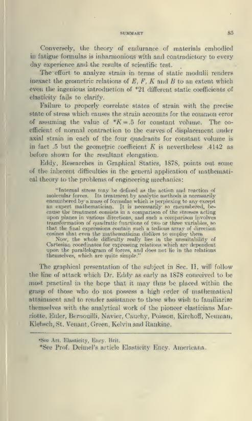
8VMMARY 85
Convereely, the theory of endurance of materials embodied
in fatigue formulas is inhanuonious with and contradictory to every
day experience and the results of scientific test.
The effort to analyze strain in terms of static modulii renders
inexact the Kcoraetric relations of E, F, K and H to an extent which
even the ingenious introduction of 21 different static coefficients of
elasticity fails to clarify.
Failure to properly correlate states of strain with the precise
state of stress which causes the strain accounts for the common error
of assuming the value of *A' = .5 for constant volume. The co-
efficient of normal contraction to the curves of di.><placement under
axial strain in each of the four quadrants for constant volume is
in fact .5 but the geometric rcjefficient K is nevertheless .4142 as
before shown for the resultant elongation.
Eddy, Researches in Graphical Statics, 1878, points out someof the inherent difficulties in the general application of mathemati-
cal theorj' to the problems of engineering mechanics:
"Internal strew may be defined as the action and reartion of
molecular forces. Ita treatment by analytic methotis is norcjwarily
encumbered by a nuuw of fonnulac which is pon>l<*xinK to any cxM'ptan expert mathematician. It is necesRanly »o encumbered, be-cause the treatment consists in a comparison of the Btreasefl actingupon planes in various directions, and such a comparison involvestransformation of quadratic functions of two or three variables, sothat the final expressions contain such a tetlious array of directioncosines that even the mathematician di!<likcs to employ them
Now, the whole difficulty really lies in the unsuitability of
Cartesian coordinates for cxpresHinK relations which are de|)endentupon the parallcloKniin of forces, and does not lie in the relations
tnemsdves, which are quite simple."
The graphical presentation of the subject in Sec. II, will follow
the line of attack which Dr. Bxidy as early as 1878 conceivetl to be
most practical in the hope that it may thus l)e placed within the
grasp of those who do not possess a high order of mathematical
attainment and !<• irndcr assistance to those who wi-^h to familiarize
themselves with tht* analytical work of the pioneer chusticiuns Mar-riotte, Eulcr, Ik'rnouilli, Navier, C'auchy, Poisson, Kirchoff, Ncunmn,Klebsch, St. Venant, Green, Kelvin and Rankinc
•See Art. EUuticity, Ency. Brit.
•See Prof. Deimel's article Elasticity Ency. Americana.

ADVERTISEMENT
Concrete Steel ConstructionA work for the practical builder and student as well
BY
H. H. EDDY, C. E., Ph. D., Sc. D. L. L. D.
ANDC. A. P. TURNER, C. E.
PART I—BUILDINGS
WRITE TO C. A. P. TURNER COMPANY, MINNEAPOLIS, MINN.FOR
BULLETIN No. 16 (FREE)
Illustrations of Reinforced Concrete and Steel Structures
in various classes of buildings.
The C. A. P. Turner Company, license responsible constructors under the
pioneer patents of the doubly rigid and economical Spiral Flat Slab Con-struction.
2nd Floor—Under Construction—Crown Cork Assembly Factory.
Otto G. Simonson, Archt.Baltimore, Md.
Turner Spiral Mushroom System used.
Longacre Construction Co. Contra.Baltimore, Md.
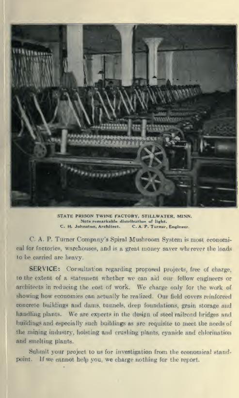
STATE PRISON TWINE FACTORY. STILLWATER. MINN.Not* rcmarkabl* dUtribution of lifht.
C. H. Johnston. Architect. C. A P. Turn«r. EnfinoM'.
' A P. Turner Company's Spiral Mushroom System is most economi-
cal for factories, warehouses, and is a Ki'^eat money saver win rever the loads
to be carTie<l are heavy.
SERVICE: Corsultat'on regarding proposed projects, free of chargi
to the extent of a statement whether we can aid our fellow engineers or
architects in reducing the cost of work. We charge only for the work of
diowing how economies can actually be realized. Our field covers reinforced
concrete buildinfpi and dams, tunnels, deep foundations, grain storage and
handling plants. We are exf)erts in the destgn of steel railrond bridges and
buildings and especially such buildinp as are requisite to meet the needs of
the mining induKtr>', hoisting and crushing plants, cyanide and chlorination
and smelting plants.
Submit your project to us for investigation frr>in th(> economical stand-
point. If we cannot help you, we charge nothing for the ri'port.
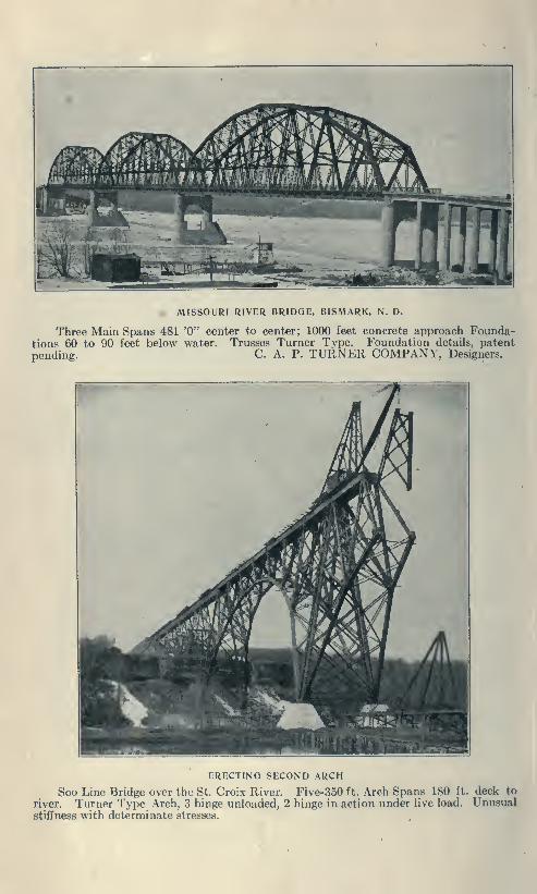
MISSOURI RIVER BRIDGE, BISMARK, N. D.
Three Main Spans 481 '0" center to center; 1000 feet concrete approach Founda-tions 60 to 90 feet below water. Trusses Turner Type. Foundation details, patentpending. C. A. P. TURNER COMPANY, Designers.
ERECTING SECOND ARCH
Soo Line Bridge over the St. Croix River. Five-350 ft. Arch Spans 180 ft. deck to
river. Turner Type Arch, 3 hinge unloaded, 2 hinge in action under live load
stiffness with determinate stresses.
Unusual


TA405T8T.l
Turner, Claude Allen PorterElasticity «md strength
of Mtterials in construction
tnftnxcnac
PLEASE DO NOT REMOVE
CARDS OR SLIPS FROM THIS POOCET
UNiVERSITY OF TORONTO LIBRARY