Embed Size (px)
Citation preview

Operating instructions for
EL6930 TwinSAFE Logic Terminal with PROFIsafe gateway Version: 1.2.0 Date: 2016-03-15


Table of contents
EL6930 1
Table of contents 1 Foreword 3
1.1 Notes on the manual 3
1.1.1 Intendent audience 3
1.1.2 Origin of the document 3
1.1.3 Actuality 3
1.1.4 Product properties 3
1.1.5 Disclaimer 3
1.1.6 Trademarks 3
1.1.7 Patent Pending 4
1.1.8 Copyright 4
1.1.9 Delivery conditions 4
1.2 Safety instructions 4
1.2.1 Delivery state 4
1.2.2 Operator's obligation to exercise diligence 4
1.2.3 Description of safety symbols 5
1.2.4 Documentation issue status 6
2 System description 7
2.1 The Beckhoff Bus Terminal system 7
2.1.1 Bus Coupler 8
2.1.2 Bus Terminals 9
2.1.3 E-bus 9
2.1.4 Power contacts 9
2.2 TwinSAFE 10
2.2.1 The I/O construction kit is extended safely 10
2.2.2 Safety concept 10
2.2.3 EL1904, EL2904 - Bus Terminals with 4 fail-safe inp uts or outputs 11
2.2.4 EL6930 - TwinSAFE logic terminal with PROFIsafe gat eway 11
2.2.5 The fail-safe principle (Fail Stop) 11
3 Product description 12
3.1 General description 12
3.2 Intended use 13
3.3 Technical data 14
3.4 Safety parameters 15
3.5 Dimensions 16
4 Operation 17
4.1 Installation 17

Table of contents
2 EL6930
4.1.1 Safety instructions 17
4.1.2 Transport / storage 17
4.1.3 Mechanical installation 18
4.1.4 Electrical installation 20
4.1.5 TwinSAFE reaction times 24
4.1.6 Tested EL2904 devices 26
4.1.7 Tested EL1904 devices 26
4.2 Configuration of the EL6930 in the TwinCAT System M anager 27
4.2.1 Configuration requirements 27
4.2.2 Inserting a Beckhoff Bus Coupler 27
4.2.3 Inserting a Beckhoff Bus Terminal 28
4.2.4 Inserting an EL6930 28
4.2.5 Address settings on the TwinSAFE terminals 29
4.2.6 Entering the TwinSAFE addresses in the System Manag er 30
4.2.7 Creating a TwinSAFE group 31
4.2.8 Append a function block 34
4.2.9 EL6930 user and version administration 40
4.2.10 Loading the project into the EL6930 41
4.2.11 Communication between TwinCAT controllers 43
4.2.12 Creating the PROFIsafe slave connection 47
4.3 Commissioning on Siemens F-CPU 50
4.3.1 Requirement 50
4.3.2 Installing the EL6930 in Step7 50
4.3.3 Configuration of the hardware 51
4.4 Diagnostics 54
4.4.1 Diagnostic LEDs 54
4.4.2 Diagnostic object 55
4.4.3 Status LEDs 56
4.5 Maintenance 57
4.5.1 Cleaning 57
4.6 Service life 57
4.6.1 Decommissioning 57
4.6.2 Disposal 57
5 Appendix 58
5.1 Beckhoff Support and Service 58
5.1.1 Beckhoff branches and partner companies Beckhoff Su pport 58
5.1.2 Beckhoff company headquarters 58
5.2 Certificates 59

Foreword
EL6930 3
1 Foreword
1.1 Notes on the manual
1.1.1 Intendent audience
It is essential that the following notes and explanations are followed when installing and commissioning these components.
This description is only intended for the use of trained specialists in control and automation engineering who are familiar with the applicable national standards. The responsible staff must ensure that the application or use of the products described satisfy all the requirements for safety, including all the relevant laws, regulations, guidelines and standards.
1.1.2 Origin of the document
These operating instructions were originally written in German. All other languages are derived from the German original.
1.1.3 Actuality
Please check whether you have the latest and valid version of this document. On the Beckhoff homepage under the link http://www.beckhoff.de/english/download/twinsafe.htm you may find the latest version for download. If in doubt, please contact the technical support (see chapter 5.1 Beckhoff Support and Service).
1.1.4 Product properties
Valid are only the product properties that are specified in the respectively current user documentation. Other information, which is given on the product pages of the Beckhoff homepage, in emails or other publications is not relevant.
1.1.5 Disclaimer
The documentation has been prepared with care. The products described are, however, constantly under development. For that reason the documentation is not in every case checked for consistency with performance data, standards or other characteristics. If it should contain technical or editorial errors, we reserve the right to make changes at any time and without notice. No claims for the modification of products that have already been supplied may be made on the basis of the data, diagrams and descriptions in this documentation.
1.1.6 Trademarks
Beckhoff®, TwinCAT®, EtherCAT®, Safety over EtherCAT®, TwinSAFE® and XFC® are registered trademarks of and licensed by Beckhoff Automation GmbH. Other designations used in this publication may be trademarks whose use by third parties for their own purposes could violate the rights of the owners.

Foreword
4 EL6930
1.1.7 Patent Pending
The EtherCAT technology is patent protected, in particular by the following applications and patents: EP1590927, EP1789857, DE102004044764, DE102007017835 with the corresponding applications and registrations in various other countries.
The TwinCAT technology is patent protected, in particular by the following applications and patents: EP0851348, US6167425 with corresponding applications or registrations in various other countries.
EtherCAT® is registered trademark and patented technology, licensed by Beckhoff Automation GmbH, Germany
1.1.8 Copyright
© Beckhoff Automation GmbH & Co. KG. The reproduction, distribution and utilization of this document as well as the communication of its contents to others without express authorization are prohibited. Offenders will be held liable for the payment of damages. All rights reserved in the event of the grant of a patent, utility model or design.
1.1.9 Delivery conditions
In addition, the general delivery conditions of the company Beckhoff Automation GmbH & Co. KG apply.
1.2 Safety instructions
1.2.1 Delivery state
All the components are supplied in particular hardware and software configurations appropriate for the application. Modifications to hardware or software configurations other than those described in the documentation are not permitted, and nullify the liability of Beckhoff Automation GmbH & Co. KG.
1.2.2 Operator's obligation to exercise diligence
The operator must ensure that • the TwinSAFE products are only used as intended (see chapter Product description); • the TwinSAFE products are only operated in sound condition and in working order. • the TwinSAFE products are operated only by suitably qualified and authorized personnel. • the personnel is instructed regularly about relevant occupational safety and environmental
protection aspects, and is familiar with the operating instructions and in particular the safety instructions contained herein.
• the operating instructions are in good condition and complete, and always available for reference at the location where the TwinSAFE products are used.
• none of the safety and warning notes attached to the TwinSAFE products are removed, and all notes remain legible.

Foreword
EL6930 5
1.2.3 Description of safety symbols
The following safety symbols are used in this operating manual. They are intended to alert the reader to the associated safety instructions.
DANGER
Serious risk of injury!
Failure to follow the safety instructions associated with this symbol directly endangers the life and health of persons.
WARNING
Caution - Risk of injury!
Failure to follow the safety instructions associated with this symbol endangers the life and health of persons.
CAUTION
Personal injuries!
Failure to follow the safety instructions associated with this symbol can lead to injuries to persons.
Attention
Damage to the environment or devices
Failure to follow the instructions associated with this symbol can lead to damage to the environment or equipment.
Note
Tip or pointer
This symbol indicates information that contributes to better understanding.
Foreword
6 EL6930
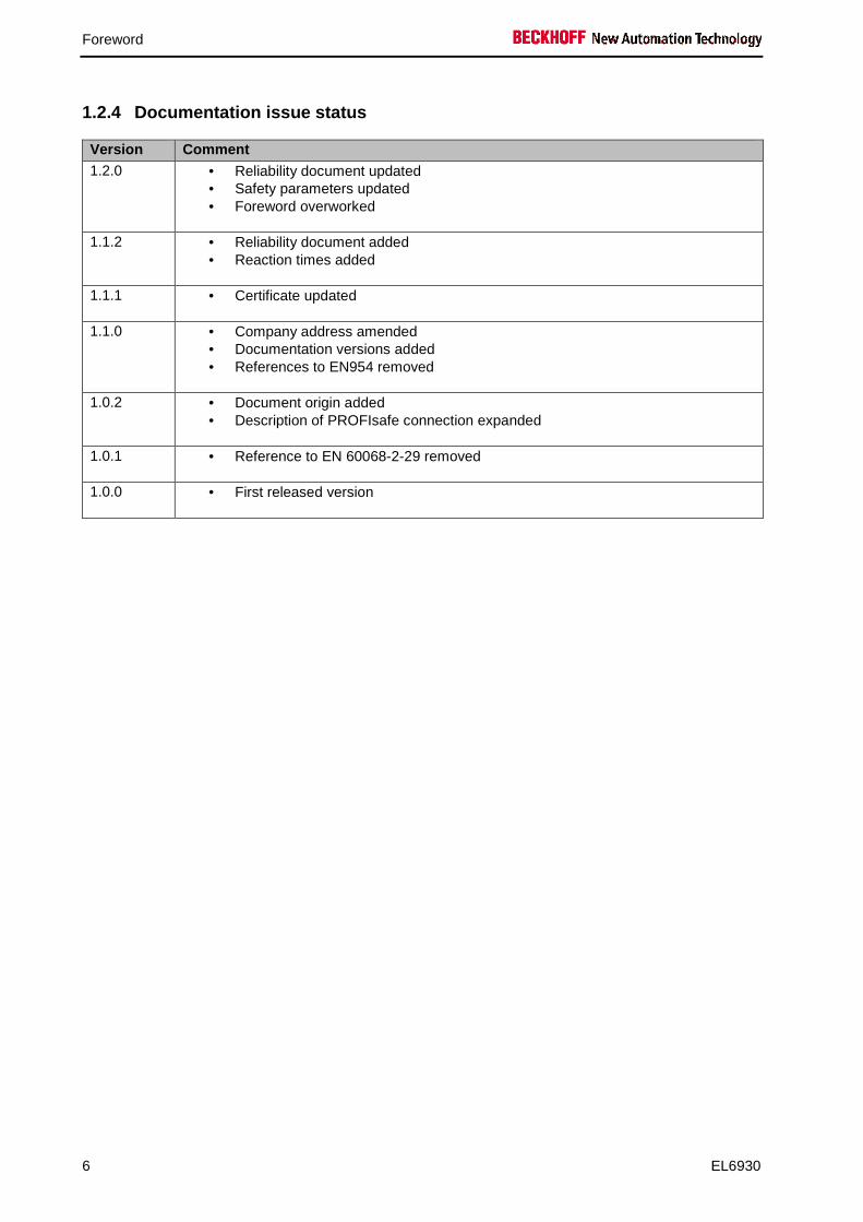
1.2.4 Documentation issue status
Version Comment 1.2.0 • Reliability document updated
• Safety parameters updated • Foreword overworked
1.1.2 • Reliability document added • Reaction times added
1.1.1 • Certificate updated
1.1.0 • Company address amended • Documentation versions added • References to EN954 removed
1.0.2 • Document origin added • Description of PROFIsafe connection expanded
1.0.1 • Reference to EN 60068-2-29 removed
1.0.0 • First released version
System description
EL6930 7
2 System description
2.1 The Beckhoff Bus Terminal system
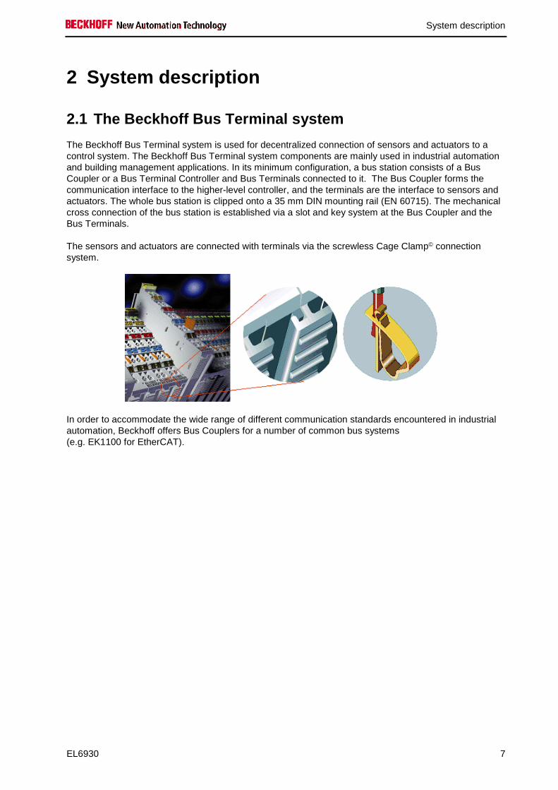
The Beckhoff Bus Terminal system is used for decentralized connection of sensors and actuators to a control system. The Beckhoff Bus Terminal system components are mainly used in industrial automation and building management applications. In its minimum configuration, a bus station consists of a Bus Coupler or a Bus Terminal Controller and Bus Terminals connected to it. The Bus Coupler forms the communication interface to the higher-level controller, and the terminals are the interface to sensors and actuators. The whole bus station is clipped onto a 35 mm DIN mounting rail (EN 60715). The mechanical cross connection of the bus station is established via a slot and key system at the Bus Coupler and the Bus Terminals.
The sensors and actuators are connected with terminals via the screwless Cage Clamp© connection system.
In order to accommodate the wide range of different communication standards encountered in industrial automation, Beckhoff offers Bus Couplers for a number of common bus systems (e.g. EK1100 for EtherCAT).
System description
8 EL6930
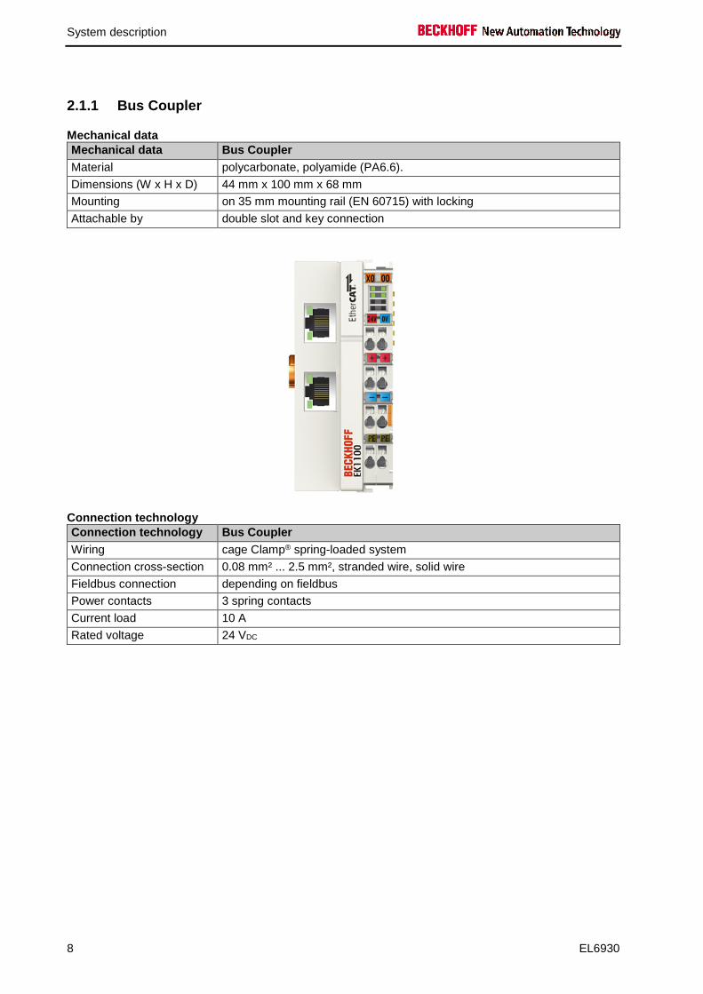
2.1.1 Bus Coupler
Mechanical data Mechanical data Bus Coupler Material polycarbonate, polyamide (PA6.6).
Dimensions (W x H x D) 44 mm x 100 mm x 68 mm
Mounting on 35 mm mounting rail (EN 60715) with locking
Attachable by double slot and key connection
Connection technology Connection technology Bus Coupler Wiring cage Clamp® spring-loaded system
Connection cross-section 0.08 mm² ... 2.5 mm², stranded wire, solid wire
Fieldbus connection depending on fieldbus
Power contacts 3 spring contacts
Current load 10 A
Rated voltage 24 VDC

System description
EL6930 9
2.1.2 Bus Terminals
Mechanical data Mechanical data Bus Terminal Material polycarbonate, polyamide (PA6.6).
Dimensions (W x H x D) 12 mm x 100 mm x 68 mm or 24 mm x 100 mm x 68 mm
Mounting on 35 mm mounting rail (EN 60715) with locking
Attachable by double slot and key connection
Connection technology Connection technology Bus Terminal Wiring cage Clamp® spring-loaded system
Connection cross-section 0.08 mm² ... 2.5 mm², stranded wire, solid wire
Fieldbus connection E-bus
Power contacts up to 3 blade/spring contacts
Current load 10 A
Rated voltage depends on Bus Terminal type
2.1.3 E-bus
The E-bus is the data path within a terminal strip. The E-bus is led through from the Bus Coupler through all the terminals via six contacts on the terminals' side walls.
2.1.4 Power contacts
The operating voltage is passed on to following terminals via three power contacts. Terminal strip can be split into galvanically isolated groups by means of potential feed terminals as required. The power feed terminals play no part in the control of the terminals, and can be inserted at any locations within the terminal strip.

System description
10 EL6930
2.2 TwinSAFE
2.2.1 The I/O construction kit is extended safely
With the TwinSAFE Terminals, Beckhoff offers the option of simply expanding the proven Bus Terminal system, and to transfer the complete cabling for the safety circuit into the already existing fieldbus cable. Safe signals can be mixed with standard signals without restriction. This saves design effort, installation and material. Maintenance is simplified significantly through faster diagnosis and simple replacement of only a few components.
The new ELx9xx series Bus Terminals only include three basic functionalities: digital inputs EL19xx, digital outputs EL29xx and a logic unit EL6930. For a large number of applications, all sensors and actuators can be wired on these Bus Terminals. The required logical link of the inputs and the outputs is handled by the EL6930. For small to medium-sized configurations, the tasks of a fail-safe PLC can thus be handled within the Bus Terminal system.
2.2.2 Safety concept
TwinSAFE: Safety and I/O technology in one system • Extension of the familiar Beckhoff I/O system with TwinSAFE terminals • Freely selectable mix of safe and standard signals • Logical link of the I/Os in the EL6930 TwinSAFE logic terminal • Safety-relevant networking of machines via bus systems
TwinSAFE protocol (FSoE) • Transfer of safety-relevant data via any media (“genuine black channel”) • TwinSAFE communication via fieldbus systems such as EtherCAT, Lightbus, PROFIBUS or
Ethernet • IEC 61508:2010 SIL 3 compliant
Configuring instead of wiring: the TwinSAFE configu rator • Configuration of the TwinSAFE system via the TwinCAT System Manager • System Manager for editing and displaying all bus parameters • Certified function blocks such as emergency stop, operation mode, etc. • Simple handling • Typical function blocks for machine safety • any bus connection with the EL6930 TwinSAFE logic terminal
TwinSAFE logic Bus Terminal EL6930 • Link unit between TwinSAFE input and output terminals • Configuration of a simple, flexible, cost-effective, decentralized safety controller • No safety requirements for higher-level control system • TwinSAFE enables networks with up to 65535 TwinSAFE devices • TwinSAFE logic terminal can establish up to 127 connections (TwinSAFE connections) and a
PROFIsafe slave connection to a PROFIsafe master controller. • Several TwinSAFE logic terminals are cascadable in a network • Safety functions such as emergency stop, protective door, etc. are already included • Suitable for applications up to SIL 3 according to IEC 61508:2010 and DIN EN ISO 13849-
1:2006 (Cat 4, PL e).

System description
EL6930 11
TwinSAFE digital input (EL1904) and output terminal (EL2904) • All current safety sensors can be connected • Operation with a TwinSAFE logic terminal • EL1904 with 4 fail-safe inputs for sensors (24 VDC) with floating contacts • EL2904 with four safe channels for actuators (24 VDC, 0.5 A per channel) • Conforming to IEC 61508:2010 SIL 3 and DIN EN ISO 13849-1:2006 (Cat 4, PL e) requirements.
2.2.3 EL1904, EL2904 - Bus Terminals with 4 fail-sa fe inputs or outputs
The EL1904 and EL2904 Bus Terminals enable connection of common safety sensors and actuators. They are operated with the EL6930 TwinSAFE logic terminal. The TwinSAFE logic terminal is the link unit between the TwinSAFE input and output terminals. It enables the configuration of a simple, flexible and cost-effective decentralized safety control system.
Therefore, there are no safety requirements for the higher-level controller! The typical safety functions required for the automation of machines, such as emergency stop, protective door, two-hand etc., are already permanently programmed in the EL6930. The user configures the EL6930 terminal according to the safety requirements of his application.
2.2.4 EL6930 - TwinSAFE logic terminal with PROFIsa fe gateway
The TwinSAFE logic terminal is the link unit between the TwinSAFE input and output terminals and a gateway to a PROFIsafe master controller. The EL6930 meets the requirements of IEC 61508:2010 SIL 3 and DIN EN ISO 13849-1:2006 (Cat 4, PL e).
2.2.5 The fail-safe principle (Fail Stop)
The basic rule for a safety system such as TwinSAFE is that failure of a part, a system component or the overall system must never lead to a dangerous condition. The safe state is always the switched off and wattless state.
Product description
12 EL6930
3 Product description
3.1 General description
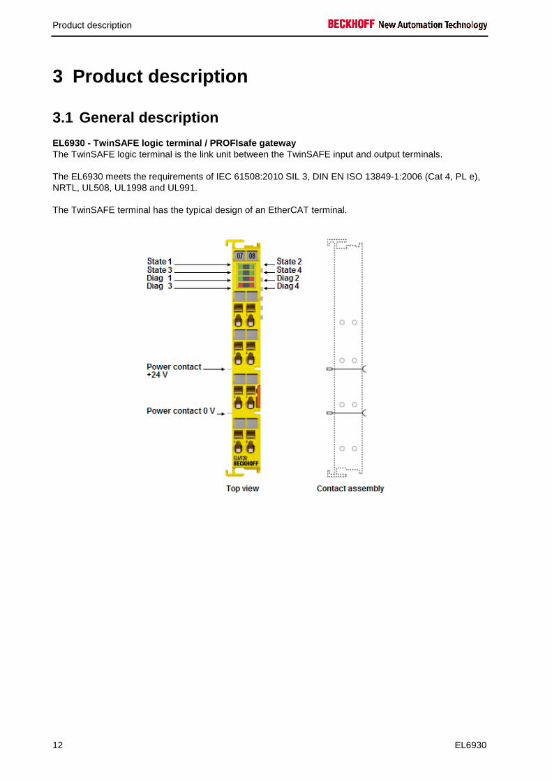
EL6930 - TwinSAFE logic terminal / PROFIsafe gatewa y The TwinSAFE logic terminal is the link unit between the TwinSAFE input and output terminals.
The EL6930 meets the requirements of IEC 61508:2010 SIL 3, DIN EN ISO 13849-1:2006 (Cat 4, PL e), NRTL, UL508, UL1998 and UL991.
The TwinSAFE terminal has the typical design of an EtherCAT terminal.

Product description
EL6930 13
3.2 Intended use
WARNING
Caution - Risk of injury!
TwinSAFE terminals may only be used for the purposes described below!
The TwinSAFE terminals expand the application range of Beckhoff Bus Terminal system with functions that enable them to be used for machine safety applications. The TwinSAFE terminals are designed for machine safety functions and directly associated industrial automation tasks. They are therefore only approved for applications with a defined fail-safe state. This safe state is the wattless state. Fail-safety according to the relevant standards is required.
The TwinSAFE terminals enable connection of: • 24 VDC sensors (EL1904) such as
emergency off pushbutton switches, pull cord switches, position switches, two-hand switches, safety mats, light curtains, light barriers, laser scanner, etc.
• 24 VDC actuators (EL2904) such as contactors, protection door switches with tumbler, signal lamps, servo drives, etc.
Note
Test pulses
When selecting actuators please ensure that the EL2904 test pulses do not lead to actuator switching or diagnostic message from the EL2904.
The following modules were developed for these tasks:
• The EL1904 terminal is an input module with digital inputs. • The EL2904 terminal is an output module with digital outputs. • The EL6930 terminal is a logic module.
These modules are suitable for operation with • Beckhoff EKxxxx series Bus Couplers • Beckhoff CXxxxx series Embedded PCs with E-bus connection
CAUTION
Follow the machinery directive
The TwinSAFE terminals may only be used in machines according to the machinery directive.
CAUTION
Ensure traceability
The buyer has to ensure the traceability of the device via the serial number.
Product description
14 EL6930
3.3 Technical data
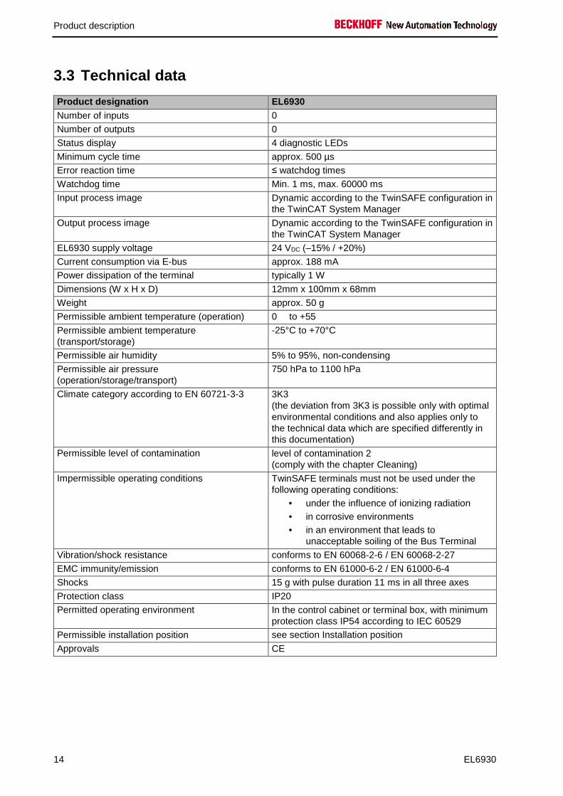
Product designation EL6930 Number of inputs 0
Number of outputs 0
Status display 4 diagnostic LEDs
Minimum cycle time approx. 500 µs
Error reaction time ≤ watchdog times
Watchdog time Min. 1 ms, max. 60000 ms
Input process image Dynamic according to the TwinSAFE configuration in the TwinCAT System Manager
Output process image Dynamic according to the TwinSAFE configuration in the TwinCAT System Manager
EL6930 supply voltage 24 VDC (–15% / +20%)
Current consumption via E-bus approx. 188 mA
Power dissipation of the terminal typically 1 W
Dimensions (W x H x D) 12mm x 100mm x 68mm
Weight approx. 50 g
Permissible ambient temperature (operation) 0 ℃ to +55 ℃
Permissible ambient temperature (transport/storage)
-25°C to +70°C
Permissible air humidity 5% to 95%, non-condensing
Permissible air pressure (operation/storage/transport)
750 hPa to 1100 hPa
Climate category according to EN 60721-3-3 3K3 (the deviation from 3K3 is possible only with optimal environmental conditions and also applies only to the technical data which are specified differently in this documentation)
Permissible level of contamination level of contamination 2 (comply with the chapter Cleaning)
Impermissible operating conditions TwinSAFE terminals must not be used under the following operating conditions:
• under the influence of ionizing radiation • in corrosive environments • in an environment that leads to
unacceptable soiling of the Bus Terminal
Vibration/shock resistance conforms to EN 60068-2-6 / EN 60068-2-27
EMC immunity/emission conforms to EN 61000-6-2 / EN 61000-6-4
Shocks 15 g with pulse duration 11 ms in all three axes
Protection class IP20
Permitted operating environment In the control cabinet or terminal box, with minimum protection class IP54 according to IEC 60529
Permissible installation position see section Installation position
Approvals CE

Product description
EL6930 15
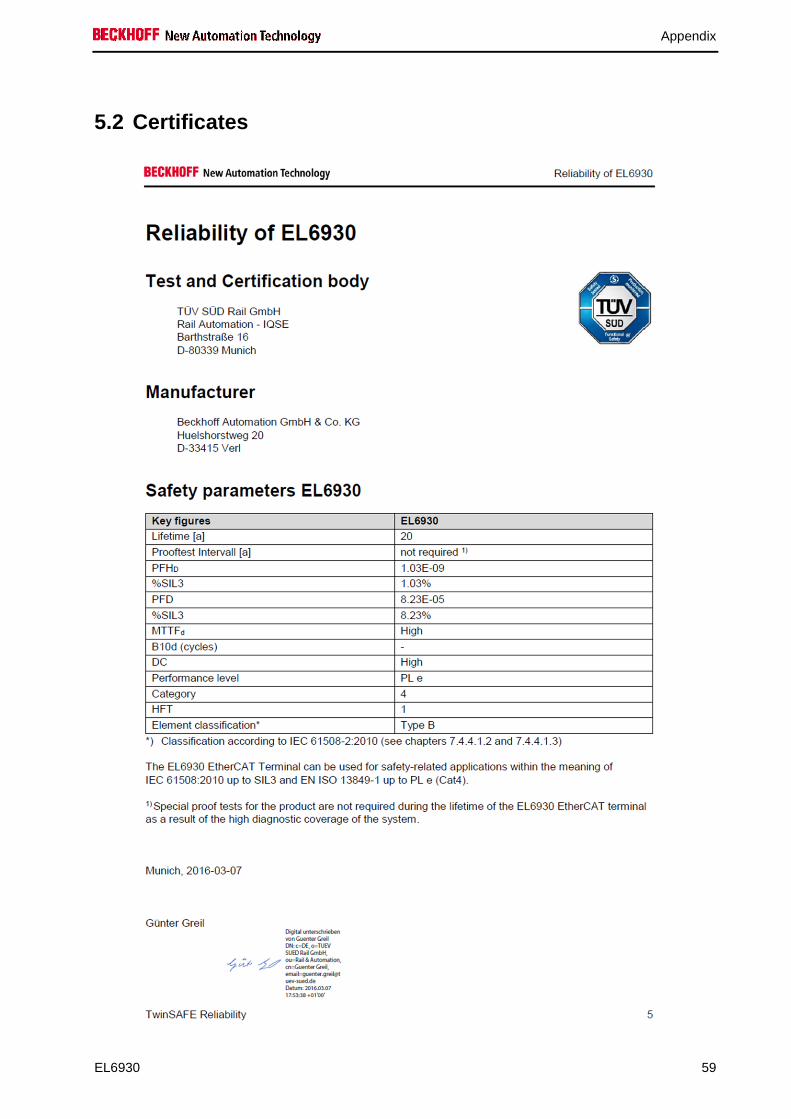
3.4 Safety parameters
Key figures EL6930 Lifetime [a] 20
Prooftest Interval [a] not required 1)
PFHD 1.03E-09
%SIL3 1,03%
PFD 8.23E-05
%SIL3 8,23%
MTTFd High
DC High
Performance level PL e
Category 4
HFT 1
Element classification* Type B
*) Classification according to IEC 61508-2:2010 (see chapter 7.4.4.1.2 and 7.4.4.1.3)
The EL6930 EtherCAT Terminal can be used for safety-related applications within the meaning of IEC 61508:2010 up to SIL3 and EN ISO 13849-1 up to PL e (Cat4).
1) Special proof tests are not required during the entire service life of the EL6930 EtherCAT terminal.
To calculate or estimate the MTTFd value out of the PFHD value please refer to the Application Guide TwinSAFE or to the ISO 13849-1:2015 table K.1.

Product description
16 EL6930
3.5 Dimensions
Width: 12 mm (side-by-side installation) Height: 100 mm Depth: 68 mm

Operation
EL6930 17
4 Operation Please ensure that the TwinSAFE terminals are only transported, stored and operated under the specified conditions (see technical data)!
WARNING
Caution - Risk of injury!
The TwinSAFE terminals must not be used under the following operating conditions: • under the influence of ionizing radiation (that exceeds the level of the natural
environmental radiation) • in corrosive environments • in an environment that leads to unacceptable soiling of the Bus Terminal
4.1 Installation
4.1.1 Safety instructions
Before installing and commissioning the TwinSAFE terminals please read the safety notes in the foreword of this documentation.
4.1.2 Transport / storage
Use the original packaging for transporting or storing the digital TwinSAFE terminals.
CAUTION
Note the specified environmental conditions
Please ensure that the digital TwinSAFE terminals are only transported and stored under the specified environmental conditions (see technical data).
Operation
18 EL6930
4.1.3 Mechanical installation
DANGER
Serious risk of injury!
Bring the bus system into a safe, de-energized state before starting installation, disassembly or wiring of the Bus Terminals!
4.1.3.1 Control cabinet
The TwinSAFE terminals must be installed in a control cabinet or terminal box with IP54 protection class according to IEC 60529 as a minimum.
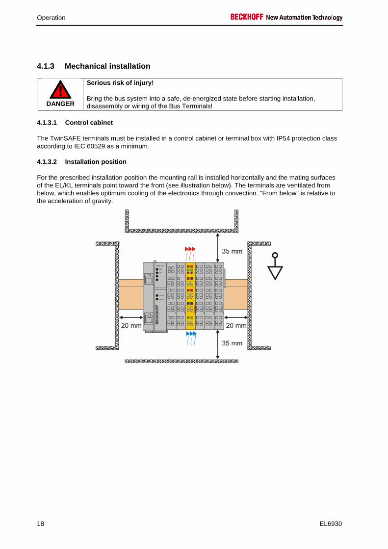
4.1.3.2 Installation position
For the prescribed installation position the mounting rail is installed horizontally and the mating surfaces of the EL/KL terminals point toward the front (see illustration below). The terminals are ventilated from below, which enables optimum cooling of the electronics through convection. "From below" is relative to the acceleration of gravity.
Operation
EL6930 19
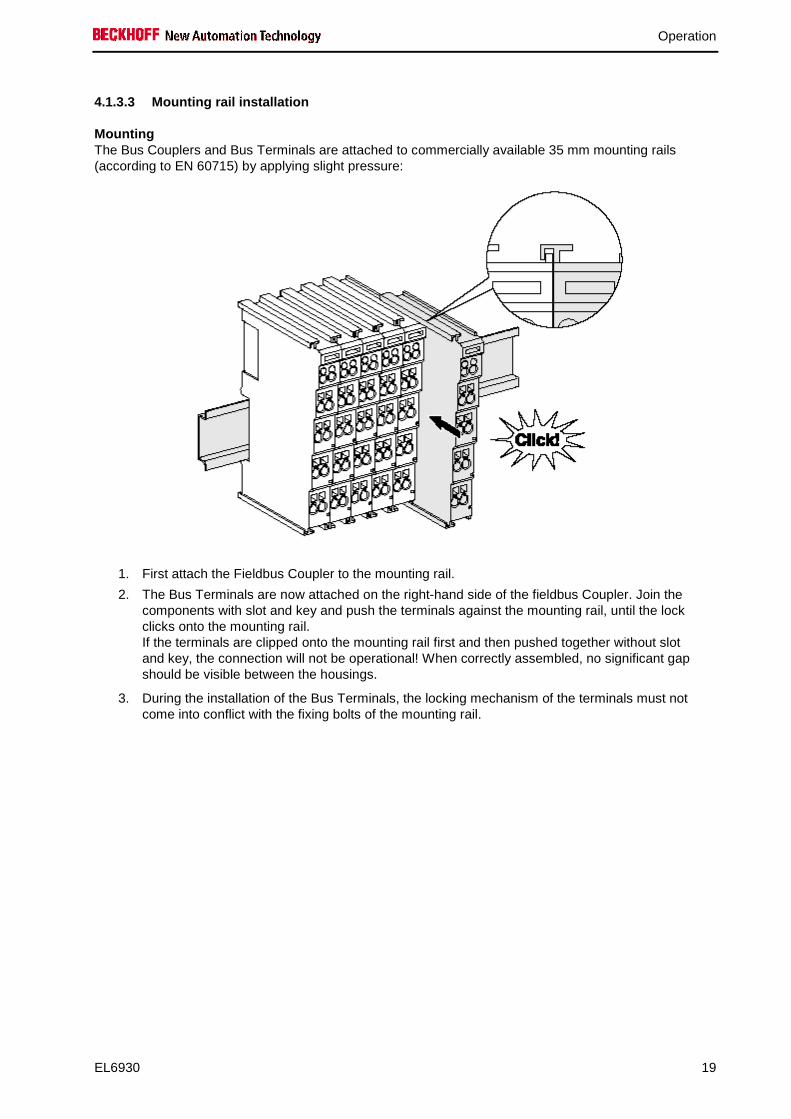
4.1.3.3 Mounting rail installation
Mounting The Bus Couplers and Bus Terminals are attached to commercially available 35 mm mounting rails (according to EN 60715) by applying slight pressure:
1. First attach the Fieldbus Coupler to the mounting rail.
2. The Bus Terminals are now attached on the right-hand side of the fieldbus Coupler. Join the components with slot and key and push the terminals against the mounting rail, until the lock clicks onto the mounting rail. If the terminals are clipped onto the mounting rail first and then pushed together without slot and key, the connection will not be operational! When correctly assembled, no significant gap should be visible between the housings.
3. During the installation of the Bus Terminals, the locking mechanism of the terminals must not come into conflict with the fixing bolts of the mounting rail.
Operation
20 EL6930
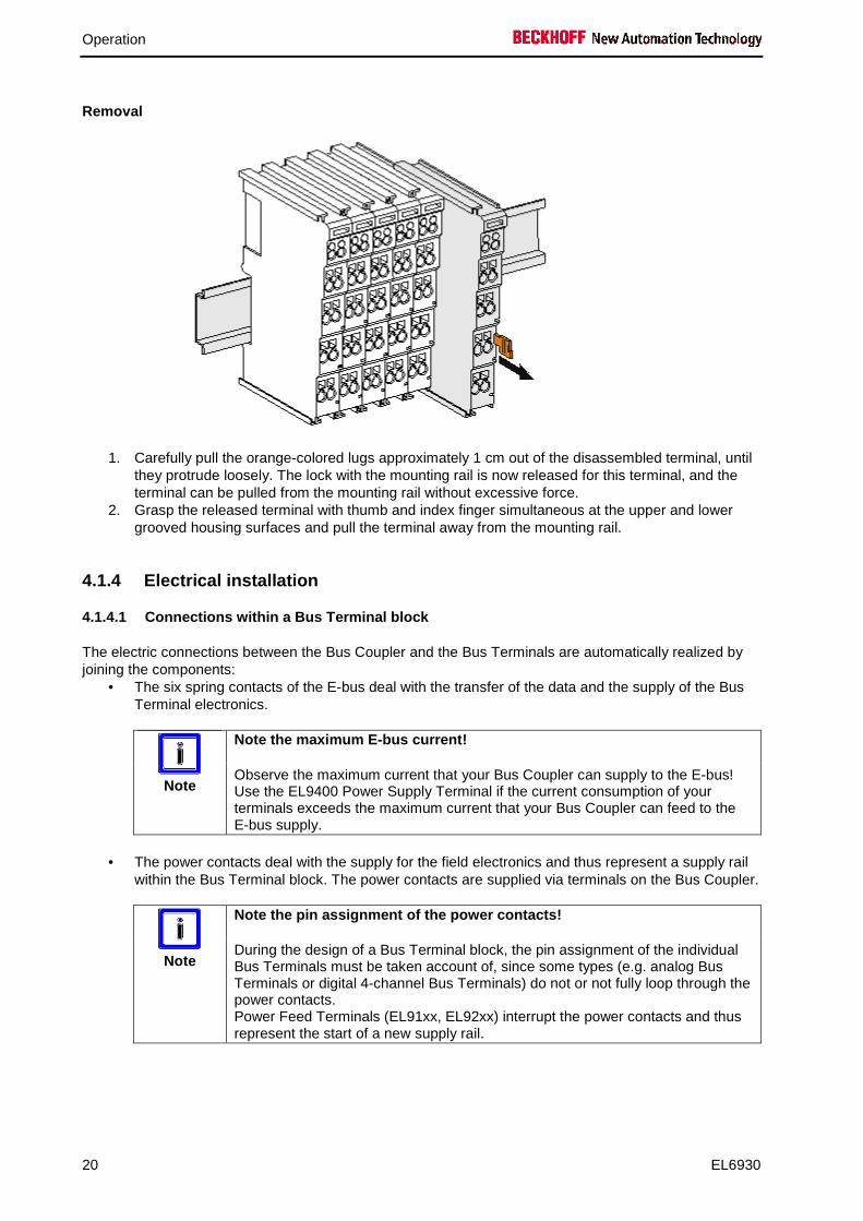
Removal
1. Carefully pull the orange-colored lugs approximately 1 cm out of the disassembled terminal, until they protrude loosely. The lock with the mounting rail is now released for this terminal, and the terminal can be pulled from the mounting rail without excessive force.
2. Grasp the released terminal with thumb and index finger simultaneous at the upper and lower grooved housing surfaces and pull the terminal away from the mounting rail.
4.1.4 Electrical installation
4.1.4.1 Connections within a Bus Terminal block
The electric connections between the Bus Coupler and the Bus Terminals are automatically realized by joining the components:
• The six spring contacts of the E-bus deal with the transfer of the data and the supply of the Bus Terminal electronics.
Note
Note the maximum E-bus current!
Observe the maximum current that your Bus Coupler can supply to the E-bus! Use the EL9400 Power Supply Terminal if the current consumption of your terminals exceeds the maximum current that your Bus Coupler can feed to the E-bus supply.
• The power contacts deal with the supply for the field electronics and thus represent a supply rail
within the Bus Terminal block. The power contacts are supplied via terminals on the Bus Coupler.
Note
Note the pin assignment of the power contacts!
During the design of a Bus Terminal block, the pin assignment of the individual Bus Terminals must be taken account of, since some types (e.g. analog Bus Terminals or digital 4-channel Bus Terminals) do not or not fully loop through the power contacts. Power Feed Terminals (EL91xx, EL92xx) interrupt the power contacts and thus represent the start of a new supply rail.
Operation
EL6930 21
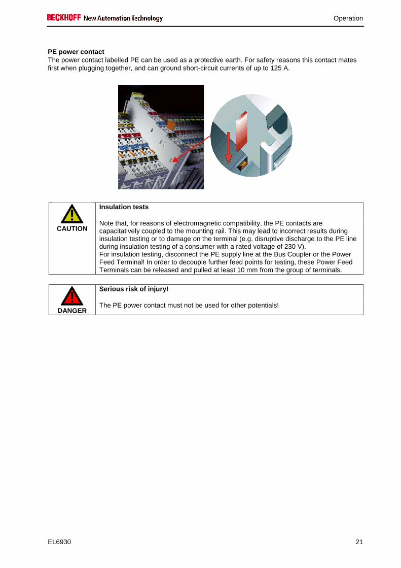
PE power contact The power contact labelled PE can be used as a protective earth. For safety reasons this contact mates first when plugging together, and can ground short-circuit currents of up to 125 A.
CAUTION
Insulation tests
Note that, for reasons of electromagnetic compatibility, the PE contacts are capacitatively coupled to the mounting rail. This may lead to incorrect results during insulation testing or to damage on the terminal (e.g. disruptive discharge to the PE line during insulation testing of a consumer with a rated voltage of 230 V). For insulation testing, disconnect the PE supply line at the Bus Coupler or the Power Feed Terminal! In order to decouple further feed points for testing, these Power Feed Terminals can be released and pulled at least 10 mm from the group of terminals.
DANGER
Serious risk of injury!
The PE power contact must not be used for other potentials!

Operation
22 EL6930
4.1.4.2 Wiring
Up to eight connections enable the connection of solid or finely stranded cables to the Bus Terminals. The terminals are implemented in spring force technology. Connect the cables as follows:
1. Open a spring-loaded terminal by slightly pushing with a screwdriver or a rod into the square opening above the terminal.
2. The wire can now be inserted into the round terminal opening without any force. 3. The terminal closes automatically when the pressure is released, holding the wire safely
and permanently.
Wire cross section 0.08 ... 2.5 mm² Strip length 8 ...9 mm

Operation
EL6930 23
EL6930 pin assignment
Terminal point
Output Signal
1 - not used, no function
2 not used, no function
3 - not used, no function
4 not used, no function
5 - not used, no function
6 not used, no function
7 - not used, no function
8 not used, no function

Operation
24 EL6930
4.1.5 TwinSAFE reaction times
The TwinSAFE terminals form a modular safety system that exchanges safety-oriented data via the Safety-over-EtherCAT protocol. This chapter is intended to help you determine the system's reaction time from the change of signal at the sensor to the reaction at the actuator.
4.1.5.1 Typical reaction time
The typical reaction time is the time that is required to transmit information from the sensor to the actuator, if the overall system is working without error in normal operation.
Definition Description RTSensor Reaction time of the sensor until the signal is provided at the interface. Typically supplied
by the sensor manufacturer.
RTInput Reaction time of the safe input, such as EL1904 or EP1908. This time can be found in the technical data. In the case of the EL1904 it is 4ms.
RTComm Reaction time of the communication This is typically 3x the EtherCAT cycle time, because new data can only be sent in a new Safety-over-EtherCAT telegram. These times depend directly on the higher-level standard controller (cycle time of the PLC/NC).
RTLogic Reaction time of the logic terminal. This is the cycle time of the logic terminal and typically ranges from 500 µs to 10 ms for the EL6900, depending on the size of the safety project. The actual cycle time can be read from the terminal.
RTOutput Reaction time of the output terminal. This typically lies within the range of 2 to 3 ms.
RTActor Reaction time of the actuator. This information is typically supplied by the actuator manufacturer
WDComm Watchdog time of the communication
������������ = ������� + ��� �� + 3 ∗ ����� + ������ + 3 ∗ ����� + ���� �� + � ����
with, for example
������������ = 5" + 4" + 3 ∗ 1" + 10" + 3 ∗ 1" + 3" + 20" = 48"
Operation
EL6930 25
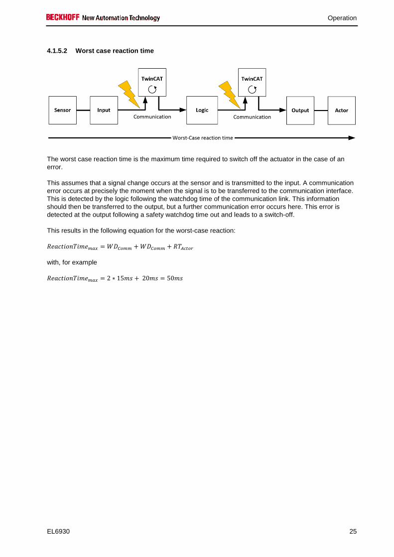
4.1.5.2 Worst case reaction time
The worst case reaction time is the maximum time required to switch off the actuator in the case of an error.
This assumes that a signal change occurs at the sensor and is transmitted to the input. A communication error occurs at precisely the moment when the signal is to be transferred to the communication interface. This is detected by the logic following the watchdog time of the communication link. This information should then be transferred to the output, but a further communication error occurs here. This error is detected at the output following a safety watchdog time out and leads to a switch-off.
This results in the following equation for the worst-case reaction:
�����������() = *+���� +*+���� + � ����
with, for example
�����������() = 2 ∗ 15" + 20" = 50"

Operation
26 EL6930
4.1.6 Tested EL2904 devices
The following list contains devices that were tested together with the EL2904 TwinSAFE terminal. The results only apply for the current device hardware version at the time of testing. The tests were carried out in a laboratory environment. Modifications of these products cannot be considered here. If you are unsure please test the hardware together with the TwinSAFE terminal.
Manufacturer Type Comment
Beckhoff AX5801 TwinSAFE Drive option card: safe restart lock
Beckhoff AX2000 AS option safe restart lock Siemens SIRIUS series S00
3RT1016-1BB42 Schütz
Telemecanique LP1K09 Schütz The tests were carried out as function tests only. The information provided in the respective manufacturer documentation remains valid.
Note
Recommended protective circuits
We recommend R/C or diode-based protective circuits for these devices. Varistor-based protective circuits should not be used.
4.1.7 Tested EL1904 devices
The following list contains devices that were tested together with the EL1904 TwinSAFE terminal. The results only apply for the current device hardware version at the time of testing. The tests were carried out in a laboratory environment. Modifications of these products cannot be considered here. If you are unsure please test the hardware together with the TwinSAFE terminal.
Manufacturer Type Comment SICK C4000 Safety light curtain SICK S3000 Safety laser scanner Wenglor SG2-14ISO45C1 Safety light grids
Leuze lumiflex ROBUST 42/43/44 Safety light barriers
Schmersal BNS250-11ZG Safety switch
ifm GM701S Inductive safety sensor
The tests were carried out as function tests only. The information provided in the respective manufacturer documentation remains valid.
Operation
EL6930 27
4.2 Configuration of the EL6930 in the TwinCAT Syst em Manager
CAUTION
Do not change the register values!
Do not change any of the CoE objects in the TwinSAFE terminals. Any modifications (e.g. via the System Manager) of the CoE objects would permanently set the terminals to the Fail-Stop state.
4.2.1 Configuration requirements
Version 2.11 build 2208 or higher of the TwinCAT automation software is required for configuring the EL6930. The current version is available for download from the Beckhoff website at www.beckhoff.de.
4.2.2 Inserting a Beckhoff Bus Coupler
See TwinCAT automation software documentation.
Operation
28 EL6930
4.2.3 Inserting a Beckhoff Bus Terminal
See TwinCAT automation software documentation.
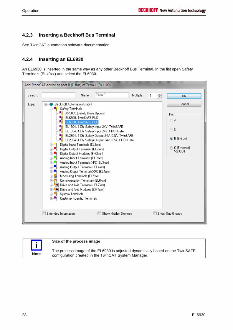
4.2.4 Inserting an EL6930
An EL6930 is inserted in the same way as any other Beckhoff Bus Terminal. In the list open Safety Terminals (ELx9xx) and select the EL6930.
Note
Size of the process image
The process image of the EL6930 is adjusted dynamically based on the TwinSAFE configuration created in the TwinCAT System Manager.

Operation
EL6930 29
4.2.5 Address settings on the TwinSAFE terminals
The TwinSAFE address of the terminal is set via the 10-way DIP switch on the left-hand side of the TwinSAFE Bus Terminal. TwinSAFE addresses between 1 and 1023 are available.
DIP switch Address 1 2 3 4 5 6 7 8 9 10
OFF OFF OFF OFF OFF OFF OFF OFF OFF OFF 0
ON OFF OFF OFF OFF OFF OFF OFF OFF OFF 1
OFF ON OFF OFF OFF OFF OFF OFF OFF OFF 2
ON ON OFF OFF OFF OFF OFF OFF OFF OFF 3
OFF OFF ON OFF OFF OFF OFF OFF OFF OFF 4
ON OFF ON OFF OFF OFF OFF OFF OFF OFF 5
OFF ON ON OFF OFF OFF OFF OFF OFF OFF 6
ON ON ON OFF OFF OFF OFF OFF OFF OFF 7
... ... ... ... ... ... ... ... ... ... ...
ON ON ON ON ON ON ON ON ON ON 1023
WARNING
Unique TwinSAFE address
Each TwinSAFE address may only be used once within a network!
Operation
30 EL6930
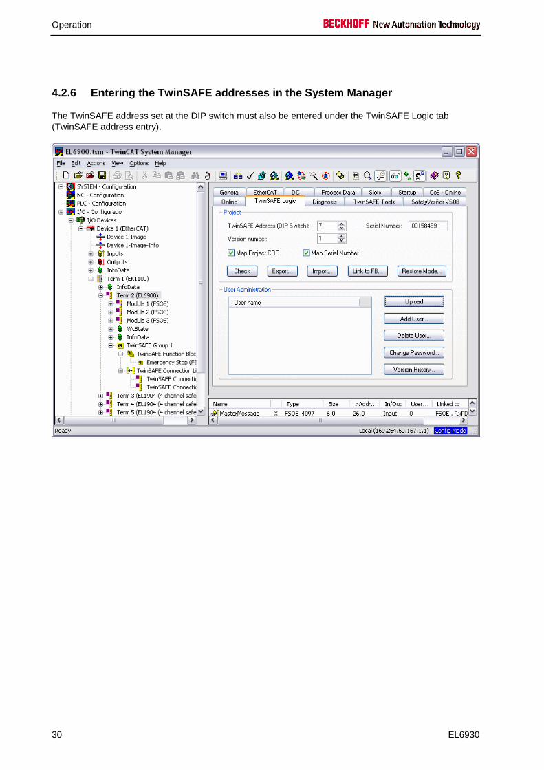
4.2.6 Entering the TwinSAFE addresses in the System Manager
The TwinSAFE address set at the DIP switch must also be entered under the TwinSAFE Logic tab (TwinSAFE address entry).

Operation
EL6930 31
4.2.7 Creating a TwinSAFE group
A TwinSAFE group is a group of TwinSAFE terminals (inputs and outputs) that are logically linked via a EL6930. Any communication faults in the TwinSAFE connections of this group lead to the whole group being switched off. Other TwinSAFE groups are not affected.
A TwinSAFE group is added by right-clicking on the associated EL6900/EL6930 in the tree structure and selecting Append TwinSAFE group in the dialog box (see diagram).

Operation
32 EL6930
4.2.7.1 TwinSAFE group signals
TwinSAFE group inputs Name Permitted type Description RUN FB-Out
Standard-In TRUE: The function blocks assigned to the TwinSAFE group are
executed. When the input is not linked it is in the TRUE state
FALSE: All of the TwinSAFE group assigned function blocks are at a STOP state and thus all associated outputs are in a safe state.
ERR Ack FB-Out Standard-In
All pending errors in the assigned function blocks and in the TwinSAFE connections are acknowledged by the FALSE->TRUE->FALSE signal sequence.

Operation
EL6930 33
TwinSAFE group outputs Name Permitted type Description FB ERR TwinSAFE-Out
FB-In Standard-Out
TRUE: At least one assigned function block has an error
FALSE: All assigned function blocks have no errors
COM ERR TwinSAFE-Out FB-In Standard-Out
TRUE: At least one TwinSAFE connection of TwinSAFE group has an error
FALSE: All TwinSAFE connections of the TwinSAFE group have no errors
OUT ERR TwinSAFE-Out FB-In Standard-Out
Always FALSE, since the EL6930 has no local outputs
Operation
34 EL6930
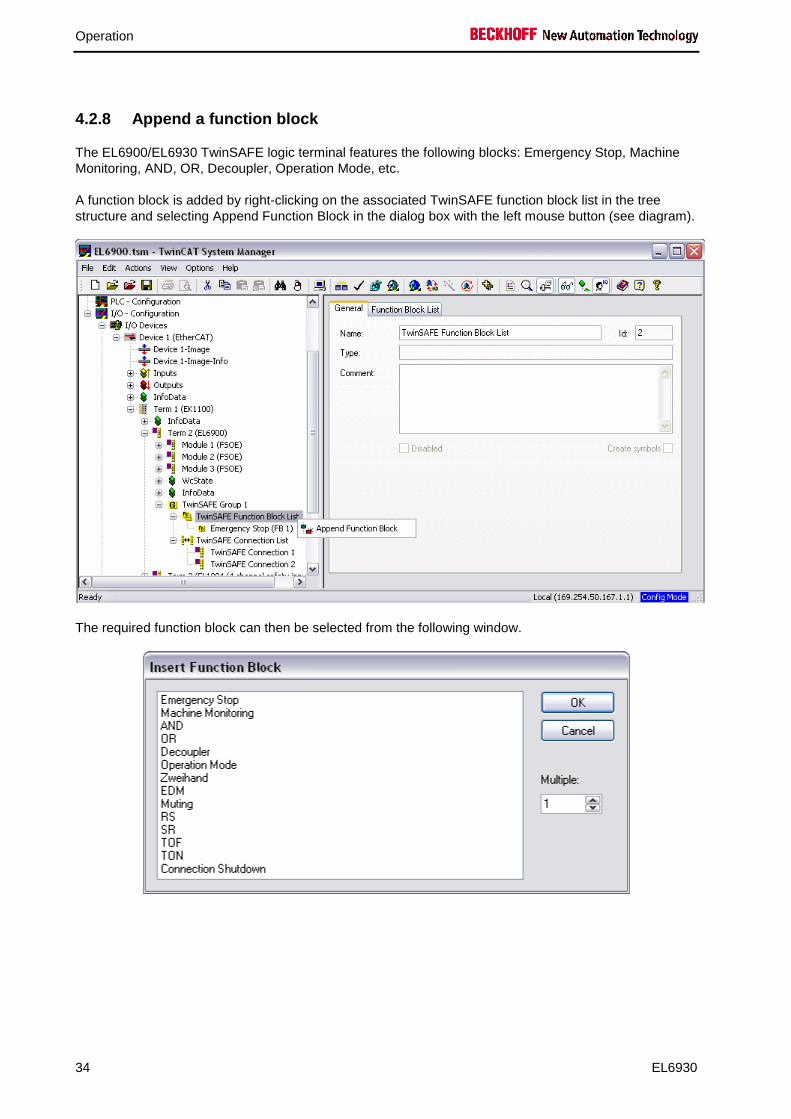
4.2.8 Append a function block
The EL6900/EL6930 TwinSAFE logic terminal features the following blocks: Emergency Stop, Machine Monitoring, AND, OR, Decoupler, Operation Mode, etc.
A function block is added by right-clicking on the associated TwinSAFE function block list in the tree structure and selecting Append Function Block in the dialog box with the left mouse button (see diagram).
The required function block can then be selected from the following window.
Operation
EL6930 35
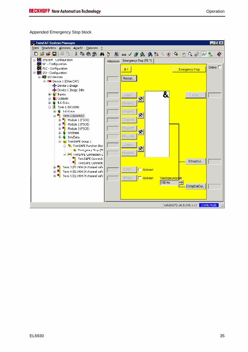
Appended Emergency Stop block

Operation
36 EL6930
4.2.8.1 Activating and configuring the block inputs
The following parameters can be set:
Deactivated: The input is not used Single-channel: The inputs are linked independent of each other Two-channel: The inputs are monitored for equality or inequality, depending on the contact type
setting. A Discrepancy Time can be set for monitoring the two inputs for simultaneous switching.
Make Contact: Contact type setting Break Contact Contact type setting
The inputs are now activated.

Operation
EL6930 37
The inputs can now be linked.
Select the variable type:
Operation
38 EL6930
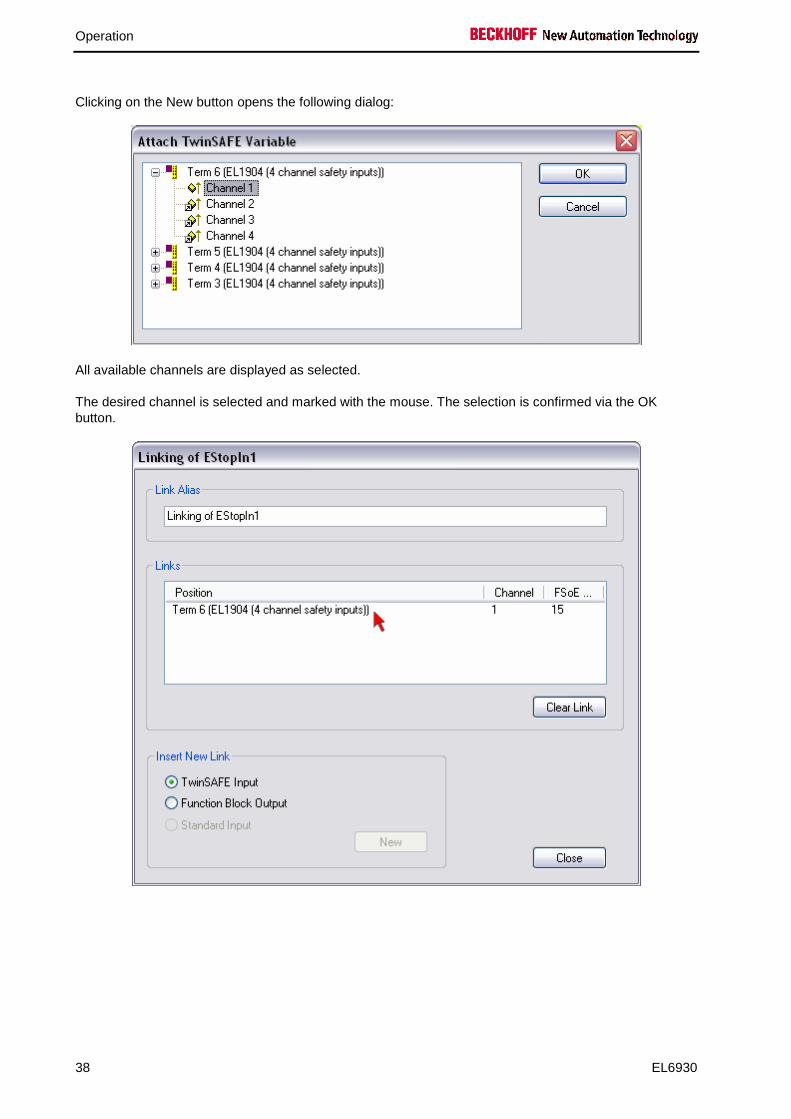
Clicking on the New button opens the following dialog:
All available channels are displayed as selected.
The desired channel is selected and marked with the mouse. The selection is confirmed via the OK button.

Operation
EL6930 39
The name of the variables should now be entered in the Link Alias field.
Repeat the process for the other inputs. Inputs that are already in use are identified with an arrow.
Operation
40 EL6930
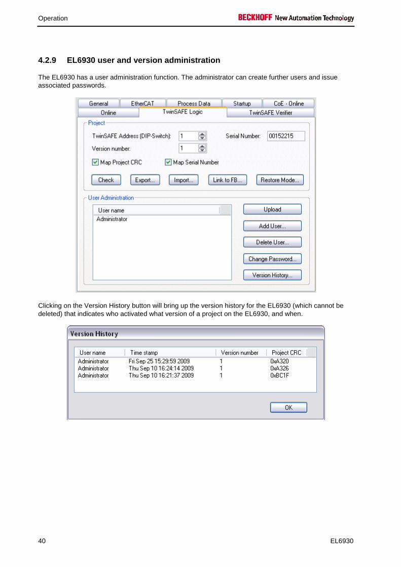
4.2.9 EL6930 user and version administration
The EL6930 has a user administration function. The administrator can create further users and issue associated passwords.
Clicking on the Version History button will bring up the version history for the EL6930 (which cannot be deleted) that indicates who activated what version of a project on the EL6930, and when.

Operation
EL6930 41
4.2.10 Loading the project into the EL6930
The project is loaded into the EL6930 via the fieldbus.
CAUTION
Use only qualified tools
Only use a qualified tool for loading, verifying and enabling the project on the EL6930!
Click the Download button on the TwinSAFE Verifier tab for loading the project.
The user must enter • his user name (default: Administrator), • the terminal serial number (printed on the outside, e.g. 197535), and • his password (default: TwinSAFE).
Note
Case-sensitive
Pay attention to upper/lower case characters for the user name and password. User name and password are case-sensitive!
The project is then displayed in text mode, and the user has to confirm consistency between the information displayed and the currently projected application by re-entering the password. The project is then started on the EL6900/EL6930.
Operation
42 EL6930
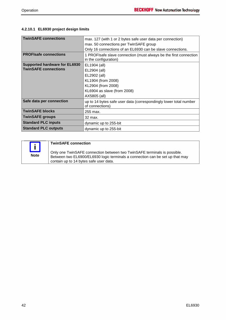
4.2.10.1 EL6930 project design limits
TwinSAFE connections max. 127 (with 1 or 2 bytes safe user data per connection) max. 50 connections per TwinSAFE group Only 16 connections of an EL6930 can be slave connections.
PROFIsafe connections 1 PROFIsafe slave connection (must always be the first connection in the configuration)
Supported hardware for EL6930 TwinSAFE connections
EL1904 (all) EL2904 (all) EL2902 (all) KL1904 (from 2008) KL2904 (from 2008) KL6904 as slave (from 2008) AX5805 (all)
Safe data per connection up to 14 bytes safe user data (correspondingly lower total number of connections)
TwinSAFE blocks 255 max. TwinSAFE groups 32 max. Standard PLC inputs dynamic up to 255-bit Standard PLC outputs dynamic up to 255-bit
Note
TwinSAFE connection
Only one TwinSAFE connection between two TwinSAFE terminals is possible. Between two EL6900/EL6930 logic terminals a connection can be set up that may contain up to 14 bytes safe user data.

Operation
EL6930 43
4.2.11 Communication between TwinCAT controllers
The MASTER_MESSAGE and SLAVE_MESSAGE data types are used for communication between two or more TwinCAT controllers via network variables.
Associated variables have to be created under Publisher and Subscriber on the communicating controllers.
During TwinSAFE communication one side acts as the master, the other one as the slave.
This results in the following data types:
TwinSAFE Master Publisher MASTER_MESSAGE TwinSAFE Master Subscriber SLAVE_MESSAGE TwinSAFE Slave Publisher SLAVE_MESSAGE TwinSAFE Slave Subscriber MASTER_MESSAGE
The link with the via TwinSAFE logic terminal EL6930 is established with the following dialog:
The connection created must now be made known to the TwinSAFE logic terminal. This is done by marking the TwinSAFE connection list and pressing the right mouse button.

Operation
44 EL6930
Create a new connection in the list of connections and create associated variables of the required type under Module1 (FSoE).
These newly-created variables are now linked with the network variables already created. This is carried out for both the master and the slave message.
Operation
EL6930 45
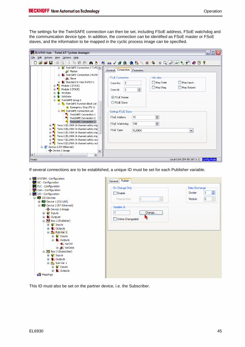
The settings for the TwinSAFE connection can then be set, including FSoE address, FSoE watchdog and the communication device type. In addition, the connection can be identified as FSoE master or FSoE slaves, and the information to be mapped in the cyclic process image can be specified.
If several connections are to be established, a unique ID must be set for each Publisher variable.
This ID must also be set on the partner device, i.e. the Subscriber.
Operation
46 EL6930
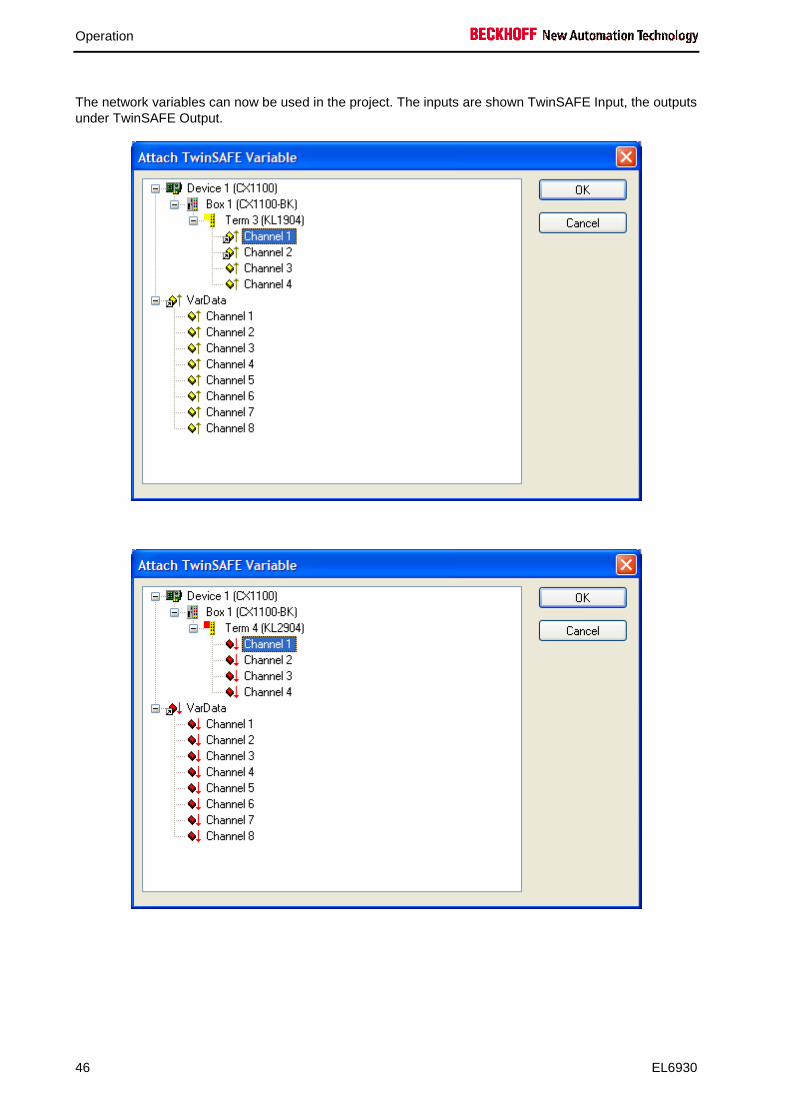
The network variables can now be used in the project. The inputs are shown TwinSAFE Input, the outputs under TwinSAFE Output.
Operation
EL6930 47
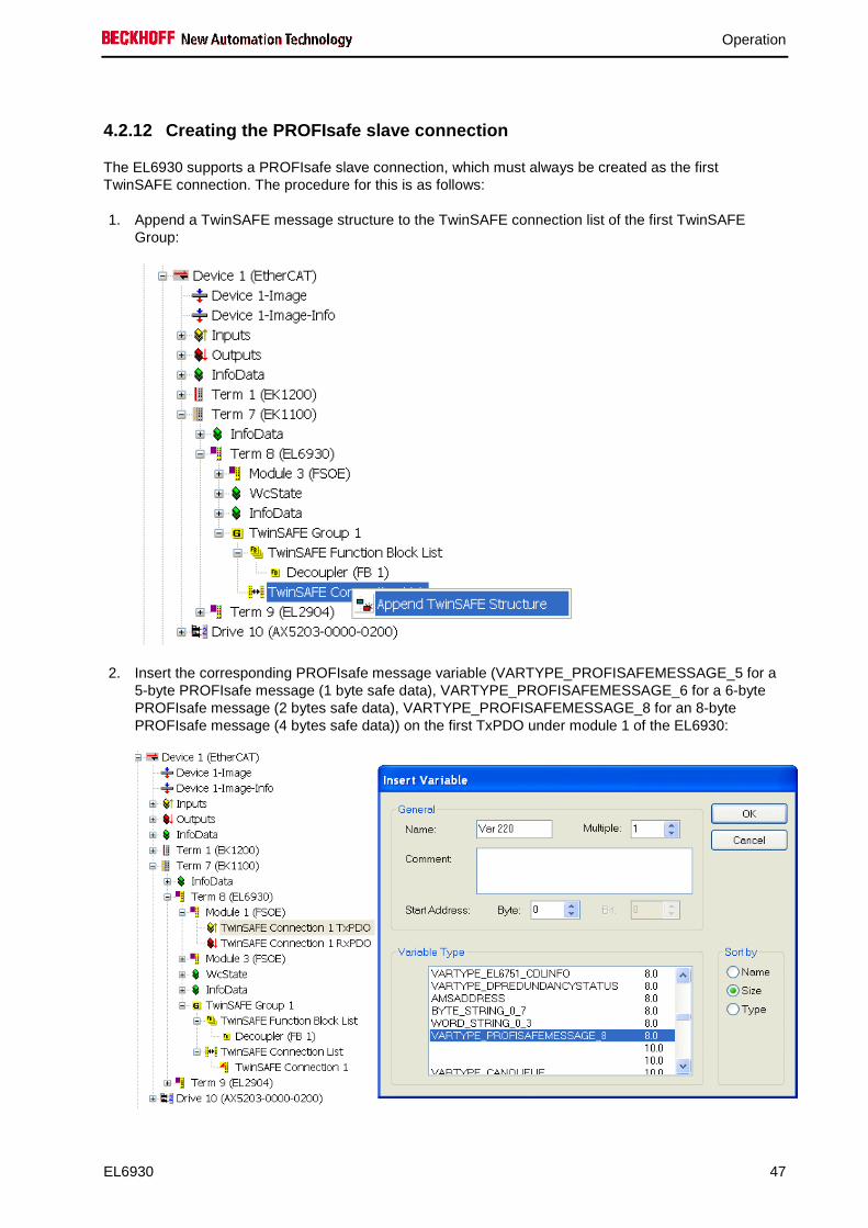
4.2.12 Creating the PROFIsafe slave connection
The EL6930 supports a PROFIsafe slave connection, which must always be created as the first TwinSAFE connection. The procedure for this is as follows:
1. Append a TwinSAFE message structure to the TwinSAFE connection list of the first TwinSAFE Group:
2. Insert the corresponding PROFIsafe message variable (VARTYPE_PROFISAFEMESSAGE_5 for a 5-byte PROFIsafe message (1 byte safe data), VARTYPE_PROFISAFEMESSAGE_6 for a 6-byte PROFIsafe message (2 bytes safe data), VARTYPE_PROFISAFEMESSAGE_8 for an 8-byte PROFIsafe message (4 bytes safe data)) on the first TxPDO under module 1 of the EL6930:
Operation
48 EL6930
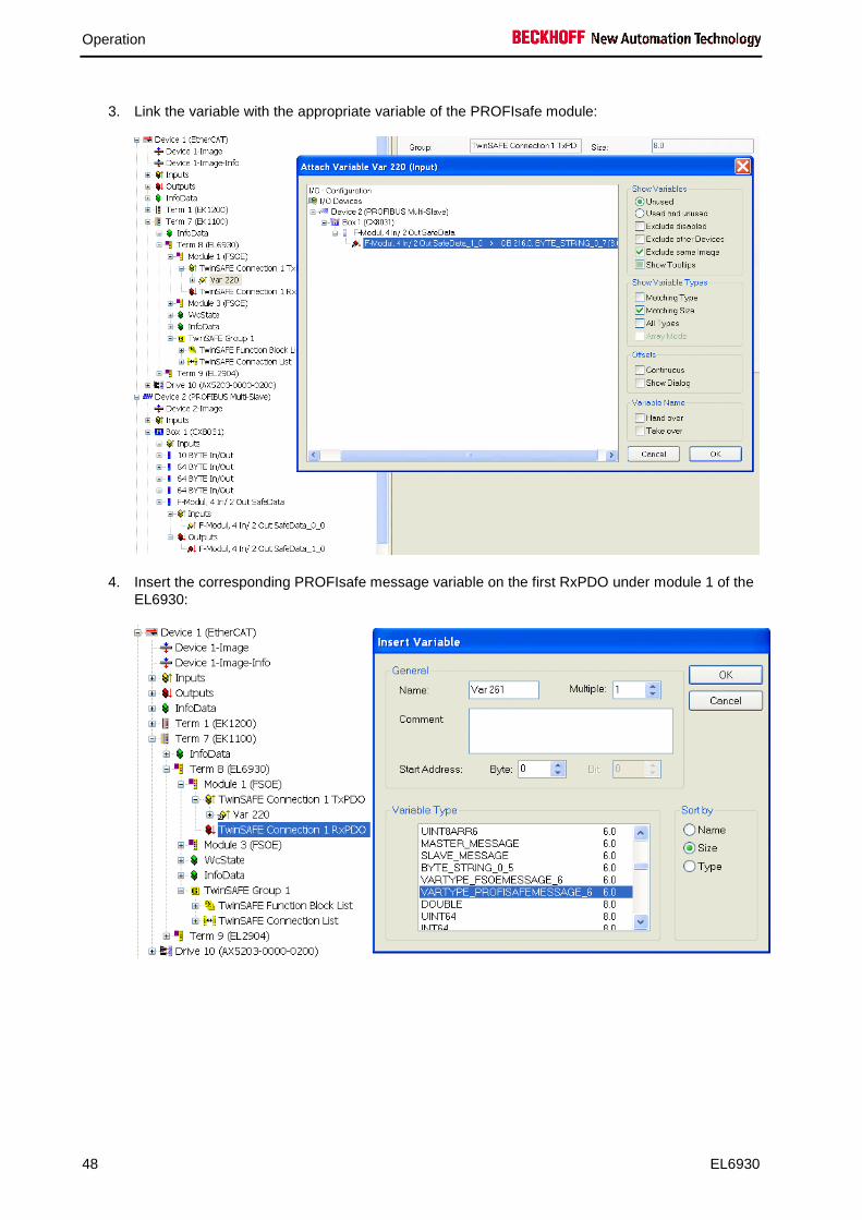
3. Link the variable with the appropriate variable of the PROFIsafe module:
4. Insert the corresponding PROFIsafe message variable on the first RxPDO under module 1 of the EL6930:
Operation
EL6930 49
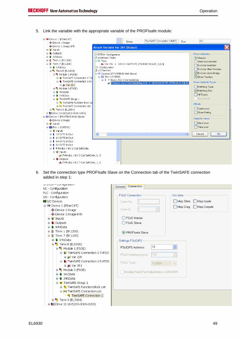
5. Link the variable with the appropriate variable of the PROFIsafe module:
6. Set the connection type PROFIsafe Slave on the Connection tab of the TwinSAFE connection added in step 1:

Operation
50 EL6930
4.3 Commissioning on Siemens F-CPU
4.3.1 Requirement
The requirement for the commissioning of the EL6930 with a PROFIsafe connection is a safety controller with PROFIBUS or PROFINET and with a certified PROFIsafe host. Furthermore the Simatic Step7 program with the extension S7 distributed Safety is needed for the configuration.
4.3.2 Installing the EL6930 in Step7
So that the EL6930 is selectable later in the device catalogue, the device description file for PROFIBUS (GSD) or PROFINET (GSDML) must be installed first. This can be done in the Step7 program HW Config as follows:

Operation
EL6930 51
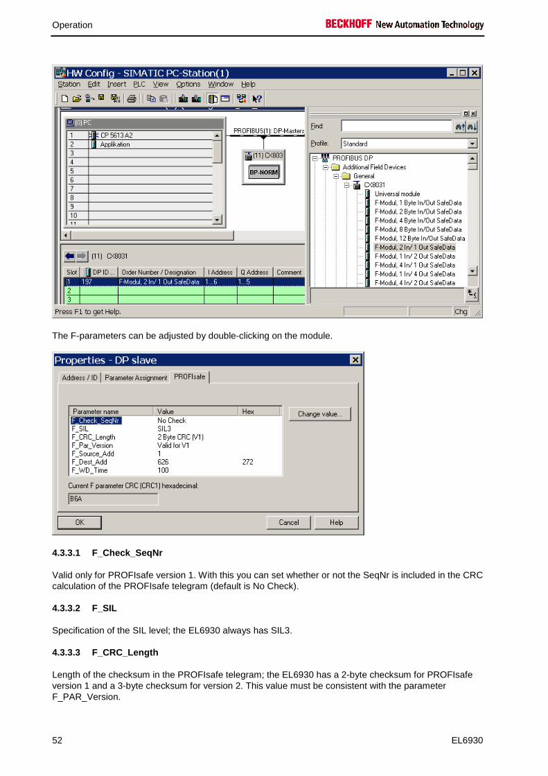
4.3.3 Configuration of the hardware
First of all the head station must be selected from the device catalogue of the HW Config (CX8031 with PROFIBUS is used here as an example).
The EL6930 presents itself to this head station as a normal module and can be added in the usual way.
Operation
52 EL6930
The F-parameters can be adjusted by double-clicking on the module.
4.3.3.1 F_Check_SeqNr
Valid only for PROFIsafe version 1. With this you can set whether or not the SeqNr is included in the CRC calculation of the PROFIsafe telegram (default is No Check).
4.3.3.2 F_SIL
Specification of the SIL level; the EL6930 always has SIL3.
4.3.3.3 F_CRC_Length
Length of the checksum in the PROFIsafe telegram; the EL6930 has a 2-byte checksum for PROFIsafe version 1 and a 3-byte checksum for version 2. This value must be consistent with the parameter F_PAR_Version.
Operation
EL6930 53
4.3.3.4 F_PAR_Version
Indicates the version of the PROFIsafe connection. The EL6930 supports PROFIsafe versions 1 and 2. This value must be consistent with the parameter F_CRC_Length.
4.3.3.5 F_Source_Add
Address of the PROFIsafe host; this is specified by the configuration program.
4.3.3.6 F_Dest_Add
Address of the PROFIsafe device; this is assigned by the user and must be unique in the entire safety network.
4.3.3.7 F_WD_Time
This parameter sets the watchdog for the safety connection. The value must always be higher than the cycle time of the fieldbus, since it can take several fieldbus cycles before a PROFIsafe telegram is dispatched.

Operation
54 EL6930
4.4 Diagnostics
4.4.1 Diagnostic LEDs
The LEDs Diag 1 to Diag 4 display diagnostic information for the EL6930.
4.4.1.1 Diag 1 LED (green)
The Diag 1 LED is currently always on when a project is loaded into the terminal.
Display Meaning
lit A project is stored in the terminal.
4.4.1.2 Diag 2 LED (red)
The Diag 2 LED indicates internal process variable errors (in preparation).
Display Meaning
in preparation
4.4.1.3 Diag 3 LED (red)
The Diag 3 LED provides further details for the Diag 4 LED (see below).
4.4.1.4 Diag 4 LED (red) if Diag 3 LED (red) is lit
If the Diag 3 LED is lit, the Diag 4 LED indicates internal terminal errors.
Diag 3 LED Diag 4 LED Source of error
lit flashing µC1
lit off µC2
Note
Returning the terminal
These errors lead to the shutdown of the terminal (global fault). The terminal must be checked by Beckhoff Automation GmbH & Co. KG.

Operation
EL6930 55
4.4.1.5 Diag 4 LED (red) if Diag 3 LED (red) is not lit.
If the Diag 3 LED is not lit, the Diag 4 LED indicates the state of the TwinSAFE terminal.
Diag 3 LED Diag 4 LED: Flashing Code Meaning
off 1 flash pulse (uniform flashing) Function block error in one of the TwinSAFE groups
off 2 flash pulses (2 pulses with longer pause in between)
Communication error in one of the TwinSAFE groups
off 3 flash pulses (3 pulses with longer pause in between)
Function block and communication error in one of the TwinSAFE groups
off Steadily lit Supply voltage or internal temperature of the terminal outside the permissible range. The diagnostic object FA00hex provides you with more detailed information.
4.4.2 Diagnostic object
The CoE object FA00hex displays further diagnostic information.
CAUTION
Do not change CoE objects!
Do not change any of the CoE objects in the TwinSAFE terminals! Any modifications (e.g. using the TwinCAT system manager) of the CoE objects would permanently set the terminals to the Fail-Stop state.
Index FA00 hex: Diagnostic object Index Name Meaning Flags Default
FA00:0 Diag RO
FA00:03 Temperature error
0005hex Maximum temperature exceeded RO 0000hex
0006hex Temperature fell below minimum
0007hex Temperature difference between the measuring points exceeded
Supply error
0101hex max. supply voltage µC1 exceeded
0102hex max. supply voltage µC2 exceeded
0103hex voltage fell below max. supply voltage µC1
0104hex voltage fell below max. supply voltage µC2

Operation
56 EL6930
4.4.3 Status LEDs
The LEDs State 1 to State 4 indicate the current status of the EL6900.
State 1 State 2 State 3 State 4 Meaning
off off off lit • No project present on the terminal
off off lit lit • Project present on the terminal • EtherCAT status: Pre-Operational (Pre-OP)
lit lit lit lit • Project present on the terminal • EtherCAT status: Operational (OP)

Operation
EL6930 57
4.5 Maintenance
The TwinSAFE terminals are maintenance-free!
WARNING
Observe the specified environmental conditions!
Please ensure that the TwinSAFE terminals are only stored and operated under the specified conditions (see technical data).
If the terminal is operated outside the ambient permitted temperature range it will switch to the Global Fault state (see chapter Diagnose).
4.5.1 Cleaning
Protect the TwinSAFE terminals from unacceptable soling during operation and storage!
If the TwinSAFE terminals were subjected to unacceptable soiling it may no longer be operated!
WARNING
Have soiled terminals checked!
Cleaning of the TwinSAFE terminals by the user is not permitted! Please send soiled terminals to the manufacturer for inspection and cleaning!
4.6 Service life
The TwinSAFE terminals are designed for a service life of 20 years.
Due to the high diagnostic coverage within the lifecycle no special proof tests are required.
4.6.1 Decommissioning
DANGER
Serious risk of injury!
Bring the bus system into a safe, de-energized state before starting disassembly of the Bus Terminals!
4.6.2 Disposal
In order to dispose of the device, it must be removed and fully dismantled. • Housing components (polycarbonate, polyamide (PA6.6)) are suitable for plastic recycling. • Metal parts can be sent for metal recycling. • Electronic parts such as disk drives and circuit boards must be disposed of in accordance with
national electronics scrap regulations.

Appendix
58 EL6930
5 Appendix
5.1 Beckhoff Support and Service
Beckhoff and their partners around the world offer comprehensive support and service, making available fast and competent assistance with all questions related to Beckhoff products and system solutions.
5.1.1 Beckhoff branches and partner companies Beckh off Support
Please contact your Beckhoff branch office or partner company for local support and service on Beckhoff products! The contact addresses for your country can be found in the list of Beckhoff branches and partner companies: www.beckhoff.com. You will also find further documentation for Beckhoff components there.
5.1.2 Beckhoff company headquarters
Beckhoff Automation GmbH & Co.KG Huelshorstweg 20 33415 Verl Germany
Phone: + 49 (0) 5246/963-0 Fax: + 49 (0) 5246/963-198 E-mail: [email protected] Web: www.beckhoff.com
Beckhoff Support Support offers you comprehensive technical assistance, helping you not only with the application of individual Beckhoff products, but also with other, wide-ranging services:
• world-wide support • design, programming and commissioning of complex automation systems • and extensive training program for Beckhoff system components
Hotline: + 49 (0) 5246/963-157 Fax: + 49 (0) 5246/963-9157 E-mail: [email protected]
Beckhoff Service The Beckhoff Service Center supports you in all matters of after-sales service:
• on-site service • repair service • spare parts service • hotline service
Hotline: + 49 (0) 5246/963-460 Fax: + 49 (0) 5246/963-479 E-mail: [email protected]
Appendix
EL6930 59
5.2 Certificates

Appendix
60 EL6930