Embed Size (px)
Citation preview
EIO0000001205 03/2012
www.schneider-electric.comEIO
0000
0012
05.0
0
Omron Corp.
Sysmac Link (Sysmac Way) (SIO) Driver03/2012

2 EIO0000001205 03/2012

Table of Contents
Safety Information . . . . . . . . . . . . . . . . . . . . . . . . . . . . . 5About the Book . . . . . . . . . . . . . . . . . . . . . . . . . . . . . . . . 7
Chapter 1 Sysmac Link (Sysmac Way) (SIO) Driver . . . . . . . . . . . 9System Structure. . . . . . . . . . . . . . . . . . . . . . . . . . . . . . . . . . . . . . . . . . 10Target Machine Serial Interface . . . . . . . . . . . . . . . . . . . . . . . . . . . . . . 11Cable Diagrams. . . . . . . . . . . . . . . . . . . . . . . . . . . . . . . . . . . . . . . . . . . 18Supported Device Addresses . . . . . . . . . . . . . . . . . . . . . . . . . . . . . . . . 25Consecutive Equipment Addresses . . . . . . . . . . . . . . . . . . . . . . . . . . . 27Environment Setup . . . . . . . . . . . . . . . . . . . . . . . . . . . . . . . . . . . . . . . . 29I/O Manager Configuration . . . . . . . . . . . . . . . . . . . . . . . . . . . . . . . . . . 31Driver Configuration . . . . . . . . . . . . . . . . . . . . . . . . . . . . . . . . . . . . . . . 32Equipment Configuration. . . . . . . . . . . . . . . . . . . . . . . . . . . . . . . . . . . . 34Device Address Configuration. . . . . . . . . . . . . . . . . . . . . . . . . . . . . . . . 35
EIO0000001205 03/2012 3

4 EIO0000001205 03/2012
§
Safety InformationImportant Information
NOTICERead these instructions carefully, and look at the equipment to become familiar with the device before trying to install, operate, or maintain it. The following special messages may appear throughout this documentation or on the equipment to warn of potential hazards or to call attention to information that clarifies or simplifies a procedure.
EIO0000001205 03/2012 5

PLEASE NOTEElectrical equipment should be installed, operated, serviced, and maintained only by qualified personnel. No responsibility is assumed by Schneider Electric for any consequences arising out of the use of this material.
A qualified person is one who has skills and knowledge related to the construction and operation of electrical equipment and its installation, and has received safety training to recognize and avoid the hazards involved.
6 EIO0000001205 03/2012

About the Book
At a Glance
Document ScopeThis manual describes the device driver communication settings in the Vijeo Designer screen editing software. Vijeo Designer enables you to design Magelis target machines that communicate with PLCs, drives, field devices, and other equipment.
For more information about Vijeo Designer and Magelis target machines, please refer to Vijeo Designer user documentation.
Validity NoteThe data and illustrations found in this book are not binding. We reserve the right to modify our products in line with our policy of continuous product development. The information in this document is subject to change without notice and should not be construed as a commitment by Schneider Electric.
Documentation ConventionsTarget Machine: Human-Machine Interface (HMI) that runs user applications designed in Vijeo Designer screen editing software. A target machine is also known as a terminal.
EIO0000001205 03/2012 7
Product Related Information
* For additional information, refer to NEMA ICS 1.1 (latest edition), “Safety Guidelines for the Application, Installation, and Maintenance of Solid State Control.“
User CommentsWe welcome your comments about this document. You can reach us by e-mail at [email protected].
WARNINGLOSS OF CONTROL
The designer of any control scheme must consider the potential failure modes of control paths and, for certain critical control functions, provide a means to achieve a safe state during and after a path failure. Examples of critical control functions are emergency stop and overtravel stop.Separate or redundant control paths must be provided for critical control functions.System control paths may include communication links. Consideration must be given to the implications of unanticipated transmission delays or failures of the link.*Each implementation of a Magelis XBTGT, HMISTO, HMISTU, HMIGTO, XBTGH, XBTGK, XBTGC, iPC, and XBTGTW must be individually and thoroughly tested for proper operation before being placed into service.
Failure to follow these instructions can result in death, serious injury, or equipment damage.
8 EIO0000001205 03/2012

EIO0000001205 03/2012
1
Sysmac Link (Sysmac Way) (SIO) DriverEIO0000001205 03/2012
Sysmac Link (Sysmac Way) (SIO) Driver
Subject of this ChapterThis chapter explains the Sysmac Link (Sysmac Way) (SIO) Driver.
What's in this Chapter?This chapter contains the following topics:
Topic Page
System Structure 10
Target Machine Serial Interface 11
Cable Diagrams 18
Supported Device Addresses 25
Consecutive Equipment Addresses 27
Environment Setup 29
I/O Manager Configuration 31
Driver Configuration 32
Equipment Configuration 34
Device Address Configuration 35
9

Sysmac Link (Sysmac Way) (SIO) Driver
System Structure
OverviewThe following table describes the system setup for connecting the target machine to Omron PLCs.
To view a cable connection diagram for a particular communication format, see Cable Diagrams.
Connection
Series CPU Link I/F Comm. Format DiagramSYSMAC C Series C200H C200H-LK201 RS-232C Cable
Diagram 1RS-232C Cable
Diagram 2RS-422 (4-wire type)
Cable Diagram 3
CPM1_CIF11 RS-422 (4-wire type)
Cable Diagram 4
CPM1_CIF01 RS-232C Cable Diagram 1
SYSMAC CV Series CVM1 Link I/F on CPU unit (HOSTLINK Port)
SYSMAC CPM Series
CPM1A
10 EIO0000001205 03/2012

Sysmac Link (Sysmac Way) (SIO) Driver
Target Machine Serial Interface
Use the following serial interface diagrams in combination with the cable diagrams in Section 3 to wire connections between the target machine and external equipment.
Magelis iPC Series (Smart, Compact, and Flex) and XBTGTW SeriesThe iPC Series (Smart, Compact, and Flex) and the XBTGTW Series target machines come with one to four COM ports. All serial ports use 9-pin D-Sub male connectors and support RS-232C serial communication. The following table illustrates the pin layout for these target machines.
COM1, COM2, COM3, OR COM4 (9-pin D-Sub Plug)RS-232C
Magelis XBTGK, XBTGC2000, XBTGH2000, and XBTGT2000 Series or higherAll XBTGK and XBTGT2000 Series and higher target machines have two COM ports: COM1 and COM2. The XBTGC2000 Series has one COM port: COM1. XBTGH2000 Series (Junction Box) has one COM port: COM1.
COM1 is a 9-pin D-Sub male connector and COM2 is an RJ45 socket. The following tables illustrate the pin layout for these target machines.
COM1 (9-pin D-Sub Plug)This COM port can act as either an RS-232C or RS-422 interface.
Pin Number Symbol Description
1 CD Carrier Detect
2 RD(RXD) Receive Data
3 SD(TXD) Transmit Data
4 ER(DTR) Data Terminal Ready
5 GND Common Ground
6 DR(DSR) Data Set Ready
7 RS(RTS) Request to Send
8 CS(CTS) Send Possible
9 CI(RI) Called status display
EIO0000001205 03/2012 11

Sysmac Link (Sysmac Way) (SIO) Driver
RS-232C
RS-422
Pin Number Symbol Description
1 CD Carrier Detect
2 RD(RXD) Receive Data
3 SD(TXD) Transmit Data
4 ER(DTR) Data Terminal Ready
5 GND Common Ground
6 DR(DSR) Data Set Ready
7 RS(RTS) Request to Send
8 CS(CTS) Send Possible
9 CI(RI) Called status display or +5V ±5% output 0.25A
Pin Number Symbol Description
1 RDA Receive Data A
2 RDB Receive Data B
3 SDA Send Data A
4 ERA Data Terminal Ready A
5 GND Common Ground
6 CSB Send Possible B
7 SDB Send Data B
8 CSA Send Possible A
9 ERB Data Terminal Ready B
Note:
When making your own connections, attach a loop back between pins 6 (CSB) and 9 (ERB), and between 4 (ERA) and 8 (CSA).To simplify the wiring, you can use the COM Port Conversion Adapter (Schneider Electric: XBTZGCOM) and Terminal Block Conversion Adapter (Schneider Electric: XBTZG949). These accessories allow access to the RS-422 signals using screw terminals. For information on the signals of the screw terminals, see the user manual for the XBTZG949.
12 EIO0000001205 03/2012

Sysmac Link (Sysmac Way) (SIO) Driver
COM2 (RJ45 Socket)
COM2 supports RS-422/485 signals only.
WARNINGUNINTENDED EQUIPMENT OPERATIONWhen making your own connections, use shielded RJ45 connectors. The shielded connector provides isolation against electromagnetic interference and provides a more secure physical connection in the RJ45 socket. Use of an improper RJ45 connection could lead to insecure connections.
Failure to follow these instructions can result in death, serious injury, or equipment damage.
Pin Number Symbol Description
1
2
3
4 D1(+) Send Data (Positive Signal)
5 D0(-) Send Data (Negative Signal)
6
7
8 GND Common Ground
EIO0000001205 03/2012 13

Sysmac Link (Sysmac Way) (SIO) Driver
Magelis HMIGTO SeriesThe HMIGTO target machines have two COM ports (COM1 and COM2), with the exception of the HMIGTO1310. The HMIGTO1310 has one COM port (COM1), which uses an RJ45 connector. For more information, see Magelis XBTGT1000, XBTGT1005, HMIGTO1310, HMISTO, and HMISTU Series.
COM1 is a 9-pin D-Sub male connector, and COM2 is an RJ45 socket. The following tables illustrate the pin layout for these target machines.
COM1 (9-pin D-Sub Plug)This COM port can act as either an RS-232C or RS-422/RS-485 interface.
RS-232C
CAUTIONLOSS OF COMMUNICATION
All connections to the communication ports must not put excessive stress on the ports.Securely attach communication cables to the panel wall or cabinet.Use only D-Sub 9-pin cables with a locking tab in good condition.
Failure to follow these instructions can result in injury or equipment damage.
Pin Number Symbol Description
1 CD Carrier Detect
2 RD(RXD) Receive Data
3 SD(TXD) Transmit Data
4 ER(DTR) Data Terminal Ready
5 SG Signal Ground
6 DR(DSR) Data Set Ready
7 RS(RTS) Request to Send
8 CS(CTS) Send Possible
9 CI(RI/VCC) Called status display or +5V ±5% output 0.25A
Shell FG Frame Ground (Common with SG)
14 EIO0000001205 03/2012

Sysmac Link (Sysmac Way) (SIO) Driver
COM2 (RJ45 Socket)
COM2 supports RS-422/485 signals only.
Note:
You can switch pin 9 between RI and VCC via software. The VCC output is not protected against overcurrent. To prevent damage or a unit malfunction, use only the rated current.You can use the Cable Connector (Omron Corporation: XMD-0901), Cable Cover (Omron Corporation: XM2S-0913), and Jack Screw #4-40 UNC (Omron Corporation: XM2Z-0073).
WARNINGUNINTENDED EQUIPMENT OPERATIONWhen making your own connections, use shielded RJ45 connectors. The shielded connector provides isolation against electromagnetic interference and provides a more secure physical connection in the RJ45 socket. Use of an improper RJ45 connection could lead to insecure connections.
Failure to follow these instructions can result in death, serious injury, or equipment damage.
Pin Number Symbol Description
1 NC –
2 NC –
3 NC –
4 Line A Transfer Data (RS-485)
5 Line B Transfer Data (RS-485)
6 RS(RTS) Request to Send
7 NC –
8 SG Signal Ground
EIO0000001205 03/2012 15

Sysmac Link (Sysmac Way) (SIO) Driver
Magelis XBTGT1000, XBTGT1005, HMIGTO1310, HMISTO, and HMISTU SeriesXBTGT1000, XBTGT1005, HMIGTO1310, HMISTO, and HMISTU Series machines come with one COM port which uses an RJ45 connector. The RJ45 socket closest to the power connector is the COM1 port. This COM port can act as an RS-422/485 interface.
DANGERELECTRIC SHOCKThe serial port is not isolated. The SG (signal ground) and FG (frame ground) terminals are connected inside the unit.
When using the SG terminal to connect an external device to the panel:
Verify that a short-circuit loop is not created when you set up the system.Connect the #8 SG terminal to remote equipment when the host (PLC) unit is not isolated. Connect the #8 SG terminal to a known reliable ground connection to reduce the risk of damaging the circuit.
Failure to follow these instructions can result in death or serious injury.
16 EIO0000001205 03/2012

Sysmac Link (Sysmac Way) (SIO) Driver
COM1 (RJ45 Socket)
RS-232C
RS-422/485 (2-wire)
WARNINGUNINTENDED EQUIPMENT OPERATIONWhen making your own connections, use shielded RJ45 connectors. The shielded connector provides isolation against electromagnetic interference and provides a more secure physical connection in the RJ45 socket. Use of an improper RJ45 connection could lead to insecure connections.
Failure to follow these instructions can result in death, serious injury, or equipment damage.
Pin Number Symbol Description
1 RD(RXD) Receive Data
2 SD(TXD) Transmit Data
3
4
5
6
7
8 GND Common Ground
Pin Number Symbol Description
1
2
3
4 D1(+) Send Data (Positive Signal)
5 D0(-) Send Data (Negative Signal)
6
7
8 GND Common Ground
EIO0000001205 03/2012 17

Sysmac Link (Sysmac Way) (SIO) Driver
Cable DiagramsThe cable diagrams illustrated below and the cable diagrams recommended by Omron may differ, however, Schneider Electric recommends using the following connection diagrams.
When creating your own cables, to identify which pins to connect on the target machine, see Target Machine Serial Interface.
Ensure that the equipment is properly grounded as indicated in the user manual and follows all applicable country standards.If a communications cable is used, the SG (signal ground) must be connected.
18 EIO0000001205 03/2012

Sysmac Link (Sysmac Way) (SIO) Driver
Diagram 1 - RS-232CTo connect the target machine and the PLC, use the recommended cables and accessories.
a. RS-232C Cable (Schneider Electric: XBTZG9731)
b. Connection Diagram
Note:
To increase electromagnetic interference resistance, Schneider Electric recommends you use twisted pair wires for your signal lines and GND (SG).
Target Machine Comments
iPC or XBTGTW Series (COM1/COM2/COM3/ COM4),XBTGK Series (COM1),XBTGC2000 Series or higher (COM1), XBTGT2000 Series or higher (COM1), XBTGH2000 Series (Junction Box COM1), HMIGTO Series (excluding HMIGTO1310) (COM1)
aRS-232C Cable (Schneider Electric: XBTZG9731 5m/16 ft)
iPC or XBTGTW Series (COM1/COM2/COM3/ COM4),XBTGK Series (COM1),XBTGC2000 Series or higher (COM1), XBTGT2000 Series or higher (COM1), XBTGH2000 Series (Junction Box COM1), HMIGTO Series (excluding HMIGTO1310) (COM1)
b Connection Digram
XBTGT1000 Series (COM1) or XBTGT1005 Series (COM1), HMIGTO1310 (COM1), HMISTO Series (COM1), HMISTU Series (COM1)
c Connection Digram
Cable / Adapter
Cable length: 15m (16 ft) max.
Target MachineSignal 25 Pin Signal
FG 1 FGSD(TXD) 3 RDRD(RXD) 2 SDRS(RTS) 8 CDCS(CTS) 20 ERSG 7 SGCD 4 RSER(DTR) 5 CSDR(DSR) 6 DR
PLCShield
EIO0000001205 03/2012 19
Sysmac Link (Sysmac Way) (SIO) Driver
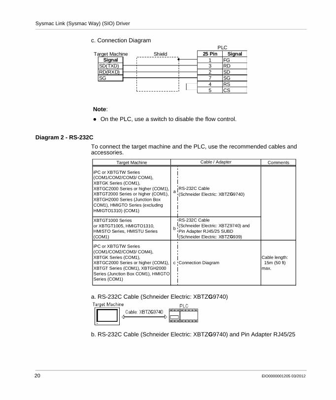
c. Connection Diagram
Diagram 2 - RS-232CTo connect the target machine and the PLC, use the recommended cables and accessories.
a. RS-232C Cable (Schneider Electric: XBTZG9740)
b. RS-232C Cable (Schneider Electric: XBTZG9740) and Pin Adapter RJ45/25
Note:
On the PLC, use a switch to disable the flow control.
Target Machine Shield 25 Pin SignalSignal 1 FG
SD(TXD) 3 RDRD(RXD) 2 SDSG 7 SG
4 RS5 CS
PLC
Target Machine Comments
iPC or XBTGTW Series (COM1/COM2/COM3/ COM4),XBTGK Series (COM1),XBTGC2000 Series or higher (COM1), XBTGT2000 Series or higher (COM1), XBTGH2000 Series (Junction Box COM1), HMIGTO Series (excluding HMIGTO1310) (COM1)
aRS-232C Cable(Schneider Electric: XBTZG9740)
XBTGT1000 Seriesor XBTGT1005, HMIGTO1310, HMISTO Series, HMISTU Series (COM1)
b
RS-232C Cable(Schneider Electric: XBTZ9740) and Pin Adapter RJ45/25 SUBD(Schneider Electric: XBTZG939)
iPC or XBTGTW Series (COM1/COM2/COM3/ COM4),XBTGK Series (COM1),XBTGC2000 Series or higher (COM1), XBTGT Series (COM1), XBTGH2000 Series (Junction Box COM1), HMIGTO Series (COM1)
c Connection DiagramCable length: 15m (50 ft) max.
Cable / Adapter
20 EIO0000001205 03/2012

Sysmac Link (Sysmac Way) (SIO) Driver
SUBD (Schneider Electric: XBTZG939)
c. Connection Diagram
Diagram 3 - RS-422 (4-wire)To connect the target machine and the PLC, use the recommended cables and accessories.
Note:
Use only the connector (XM2A-0901) and connector hood (XM2S-0911) that come with the PLC.When making your own cable connections, we recommend using Hirakawa Densen’s H-923A (CO-HC-ESV-3P*7/0.2) cable.When working with XBTGT1000 Series, XBTGT1005 Series, and HMIGTO1310 target machines, do not add the loopback connection between RS(RTS) and CS(CTS) on the target machine.
Target MachineSignal
FG 9 Pin SignalSD(TXD) 3 RDRD(RXD) 2 SDRS(RTS) 4 RSCS(CTS) 5 CSSG 9 SGCDER(DTR)
Shield PLC
FG (Connector Hood)
Target Machine CommentsXBTGK Series (COM1),XBTGC2000 Series or higher (COM1),XBTGT2000 Series or higher (COM1), XBTGH2000 Series (Junction Box COM1)
Connection DiagramCable length: 500m (1600 ft) max.
XBTGK Series (COM1),XBTGC2000 Series or higher (COM1),XBTGT2000 Series or higher (COM1), XBTGH2000 Series (Junction Box COM1)
RS-422 Cable(Schneider Electric: XBTZ9741) and Adapter (Schneider Electric: XBTZG909)
Cable length: 500m (1600 ft) max.
EIO0000001205 03/2012 21

Sysmac Link (Sysmac Way) (SIO) Driver
a. Connection Diagram
b. RS-422 Cable (Schneider Electric: XBTZ9741) and Adapter (Schneider Electric: XBTZG909)
WARNINGUNINTENDED EQUIPMENT OPERATIONTo reduce electromagnetic interference, use shielded twisted-pair cables. Connect the cable shields, then connect the cable to a single-point ground on the HMI side.
Failure to follow these instructions can result in death, serious injury, or equipment damage.
Note:
Signals A and B are opposite on the target machine and PLC.Set the PLC’s RS-232C/RS-422 toggle switch to RS-422.Use only the connector (XM2A-0901) and connector hood (XM2S-0911) that come with the PLC.When making your own cable connections, we recommend using Hirakawa Densen’s H-923A (CO-HC-ESV-3P*7/0.2) cable.
22 EIO0000001205 03/2012
Sysmac Link (Sysmac Way) (SIO) Driver
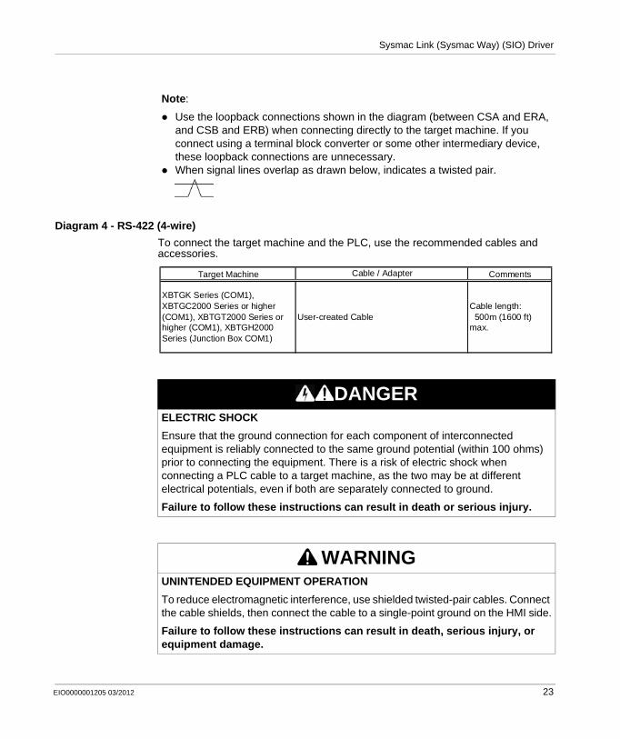
Diagram 4 - RS-422 (4-wire)To connect the target machine and the PLC, use the recommended cables and accessories.
Note:
Use the loopback connections shown in the diagram (between CSA and ERA, and CSB and ERB) when connecting directly to the target machine. If you connect using a terminal block converter or some other intermediary device, these loopback connections are unnecessary.When signal lines overlap as drawn below, indicates a twisted pair.
DANGERELECTRIC SHOCKEnsure that the ground connection for each component of interconnected equipment is reliably connected to the same ground potential (within 100 ohms) prior to connecting the equipment. There is a risk of electric shock when connecting a PLC cable to a target machine, as the two may be at different electrical potentials, even if both are separately connected to ground.
Failure to follow these instructions can result in death or serious injury.
WARNINGUNINTENDED EQUIPMENT OPERATIONTo reduce electromagnetic interference, use shielded twisted-pair cables. Connect the cable shields, then connect the cable to a single-point ground on the HMI side.
Failure to follow these instructions can result in death, serious injury, or equipment damage.
Target Machine CommentsCable / Adapter
User-created CableCable length: 500m (1600 ft) max.
XBTGK Series (COM1),XBTGC2000 Series or higher (COM1), XBTGT2000 Series or higher (COM1), XBTGH2000 Series (Junction Box COM1)
EIO0000001205 03/2012 23

Sysmac Link (Sysmac Way) (SIO) Driver
Connection Diagram
Note:
Signals A and B are opposite on the target machine and PLC.When making your own cable connections, we recommend using Hirakawa Densen’s H-923A (CO-HC-ESV-3P*7/0.2) cable.
Note:
Use the loopback connections shown in the diagram (between CSA and ERA, and CSB and ERB) when connecting directly to the target machine. If you connect using a terminal block converter or some other intermediary device, these loopback connections are unnecessary.When signal lines overlap as drawn below, indicates a twisted pair.
24 EIO0000001205 03/2012

Sysmac Link (Sysmac Way) (SIO) Driver
Supported Device Addresses
Overview
The following tables list the device address ranges you can enter from in Vijeo-Designer. For actual device address ranges supported by the PLC, refer to the corresponding PLC manual.
C Series
*1 You can define a bit address by adding a colon followed by the bit position (0-15) at the end of the word address.
*2 Read-modify-write. When you write to one of these bit addresses, the target machine reads the entire word address, sets the defined bit, then returns the new value to the PLC. If the ladder program writes data to this word address during the bit read/write process, the resulting data may be incorrect.
WARNINGUNINTENDED EQUIPMENT OPERATIONDesign your system to avoid conflicting write processes between the target machine and PLC program. Make sure that:
The target machine and PLC program do not simultaneously write to the same register.PLC programs or other devices do not write 16-bit word values to registers being accessed in a bitwise manner.
Failure to follow these instructions can result in death, serious injury, or equipment damage.
Device Bit Address*1 Word Address 16 bit
32 bit
I/O Relay*2
Internal Hold Relay*2
Analog Setup Value *2
Storage Area0000:00-9999:15 0000-9999
Data Link Relay*2 LR0000:00-LR9999:15 LR0000-LR9999Special Hold Relay*2 0000:00-9999:15 0000-9999Auxiliary Memory Relay*2 AR0000:00-AR9999:15 AR0000-AR9999Hold Relay*2 HR0000:00-HR9999:15 HR0000-HR9999Timer (contact) TIM0000-TIM9999 --Counter (contact) CNT0000-CNT9999 --Timer (current value)*4 -- TIM0000-TIM9999Counter (current value)*4 -- CNT0000-CNT9999Data Memory*2 DM0000:00-DM9999:15 DM0000-DM9999
*3
L/H *3
L/H
0000:00-9999:15 0000-9999
EIO0000001205 03/2012 25

Sysmac Link (Sysmac Way) (SIO) Driver
*3 16-bit and 32-bit data, High and Low, refer to data as defined in the following examples.
*4 The data type of Timer (current value) and Counter (current value) is fixed at BCD. When placing these items on the screen, be sure to set the display format as “DEC”.
CV Series
*1 You can define a bit address by adding a colon followed by the bit position (0-15) at the end of the word address.
*2 Read-modify-write. When you write to one of these bit addresses, the target machine reads the entire word address, sets the defined bit, then returns the new value to the PLC. If the ladder program writes data to this word address during the bit read/write process, the resulting data may be incorrect.
*3 Write operations cannot be performed on the bit device’s timer and counter.*4 16-bit and 32-bit data, High and Low, refer to data as defined in the following
examples.
*5 The data type of Timer (current value) and Counter (current value) is fixed at BCD. When placing these items on the screen, be sure to set the display format as “DEC”.
Device Bit Address*1 Word Address 16 bit
32 bit
I/O Relay*2
Internal Hold Relay*2
SYSMAC BUS/2 Remote I/O Relay*2 0000:00-9999:15 0000-9999
Data Link Relay*2 0000:00-9999:15 0000-9999Special Hold Relay*2 A000:00-A511:15 A000-A511Hold Relay*2 00000:00-9999:15 0000-9999Internal Auxiliary Relay*2 0000:00-9999:15 0000-9999SYSBUS Remote I/O Relay*2 0000:00-9999:15 0000-9999
Timer (contact) T0000-T9999*3 --Counter (contact) C0000-C9999*3 --Timer (current value)*5 -- T0000-T9999Counter (current value)*5 -- C0000-C9999Data Memory*2 D0000:00-D9999:15 D0000-D9999
*4
L/H *4L/H
0000:00-9999:15 0000-9999
26 EIO0000001205 03/2012

Sysmac Link (Sysmac Way) (SIO) Driver
Consecutive Equipment Addresses
Overview The following tables list the maximum number of consecutive addresses and the gap span (the maximum gap size between PLC device addresses that are used as consecutive device addresses) that can be read by each PLC. Refer to these tables when using block transfers.
To speed up the data communication, use consecutive device addresses on a single target machine.
C Series
Note:
When the device is setup using the methods below, the Data Communication Speed slows by the number of times the deivce is read:
When consecutive addresses exceed the maximum data number rangeWhen device types are different
DeviceMaximum
Consecutive Addresses
Gap Span
Timer (contact) (TIM)Counter (contact) (CNT)Timer (current value) (TIM)Counter (current value)(CNT)I/O RelayInternal Hold RelayData Link Relay (LR)Hold Relay (HR)Auxiliary Memory Relay (AR)Data Memory (DM)
110 bits 11 bits
120 words 12 words
EIO0000001205 03/2012 27

Sysmac Link (Sysmac Way) (SIO) Driver
CV Series
DeviceMaximum
Consecutive Addresses
Gap Span
Timer (contact) (T)Counter (contact) (C)Timer (current value) (T)Counter (current value) (C)I/O RelayInternal Hold RelaySYSMAC BUS/2 Remote I/O RelayData Link Relay (LR)Hold Relay (HR)SYSBUS Remote I/ORelaySpecial Hold Relay (A)Data Memory (D)
110 bits 11bits
120 words 12 words
28 EIO0000001205 03/2012

Sysmac Link (Sysmac Way) (SIO) Driver
Environment Setup
Overview
The following tables list Schneider Electric’s recommended communication settings for the target machine and PLC.
For details, see Driver Configuration, and Equipment Configuration.
C Series
RS-232C
WARNINGUNINTENDED EQUIPMENT OPERATIONRead and understand the instructions in this section to ensure data is properly transferred. If you do not follow these instructions, incorrect data could be written to the PLC and the target machine.
Failure to follow these instructions can result in death, serious injury, or equipment damage.
Connection Format
RS-232CConnection Format
RS-232C
Flow Control DTR(ER)/CTSTransmission Speed 19200bps Baud Rate 19200bps
Retry Count 2Parity Bit Even Parity Bit EvenStop Bit 2 bits Stop Bit 2 bitsData Length 7 bits Data Bit 7 bitsRcv. Time Out 10secTX Wait Time 0msec
Command Level
Level 1,2,3 is valid
Relation 1:NDC +5V power
supplyNo
CTS Setup Normally OnEquipment Station No. 0 Station Number 0
--
--
--
--
--
Target Machine Setup Communication Port Setup
Driver
--
--
--
EIO0000001205 03/2012 29

Sysmac Link (Sysmac Way) (SIO) Driver
CV Series
RS-232C
RS-422 (4-wire)
Serial Interface RS-232C ConnectionFormat
RS-232C
Flow Control DTR(ER)/CTSTransmission Speed 19200bps Baud Rate 19200bps
Retry Count 2Parity Bit Even Parity Bit EvenStop Bit 2 bits Stop Bit 2 BitsData Length 7 bits Data Bit 7 bitsRcv. Time Out 10secTX Wait Time 0msec
Equipment Station No. 0 Station Number 0
Target Machine Setup Communication Port Setup
Driver
--
--
----
Connection Format
RS-422(4-wire type)
Connection Format
RS-422
Flow Control NoneTransmission Speed 19200bps Baud Rate 19200bps
Retry Count 2Parity Bit Even Parity Bit EvenStop Bit 2 bits Stop Bit 2 bitsData Length 7 bits Data Length 7 bitsRcv. Time Out 10secTX Wait Time 0msec
Equipment Station No. 0 Station Number 0
Communication Port SetupTarget Machine Setup
--
--Driver
----
30 EIO0000001205 03/2012

Sysmac Link (Sysmac Way) (SIO) Driver
I/O Manager Configuration
OverviewThe driver and equipment, which enable communication between the target machine and the PLC, depends on the PLC type.
Screen example of I/O Manager Configuration
Note:
For information on how to display the [New Driver] dialog box, see the Vijeo Designer Help.
EIO0000001205 03/2012 31

Sysmac Link (Sysmac Way) (SIO) Driver
Driver Configuration
Overview
To configure the communication settings of the serial driver in the target machine, use the [Driver Configuration] dialog box. Make sure the settings match those of the PLC.
For an overview of the driver and device settings, see Environment Setup.
Screen example of Driver Configuration
WARNINGUNINTENDED EQUIPMENT OPERATIONRead and understand the instructions in this section to ensure data is properly transferred. If you do not follow these instructions, incorrect data could be written to the PLC and the target machine.
Failure to follow these instructions can result in death, serious injury, or equipment damage.
Note:
For information on how to display the [Driver Configuration] dialog box, see the Vijeo Designer Help.
32 EIO0000001205 03/2012

Sysmac Link (Sysmac Way) (SIO) Driver
Screen Description
Area Description
Manufacturer Displays the name of the PLC manufacturer.
Driver Displays the type of serial connection used to connect the target machine to the PLC. This property is read-only.
COM Port Defines which COM port to use on the target machine, for connecting to the PLC.
Serial Interface Defines the serial connection: RS-232C or RS-422 (4-wire).For details about the supported connections, see Cable Diagrams.
Flow Control Defines the signals that control the data flow.
Transmission Speed
Sets the communication speed in bits per second. This setting must match the PLC baud rate.
Retry Count Defines the number of times the driver tries to send or receive data when an error has been detected.
Parity Bit Sets either a parity bit [Even or Odd] for use in detecting communication errors, or [None] at all.
Stop Bit Defines the length of the stop bit.
Data Length Defines the length of each unit of data.
Rcv. Timeout Defines the length of time the target machine waits for a response before it outputs a timeout error or sends another communication.
TX Wait Time Defines the number of milliseconds that the target machine waits, after receiving a communication packet, before sending a response.
EIO0000001205 03/2012 33
Sysmac Link (Sysmac Way) (SIO) Driver
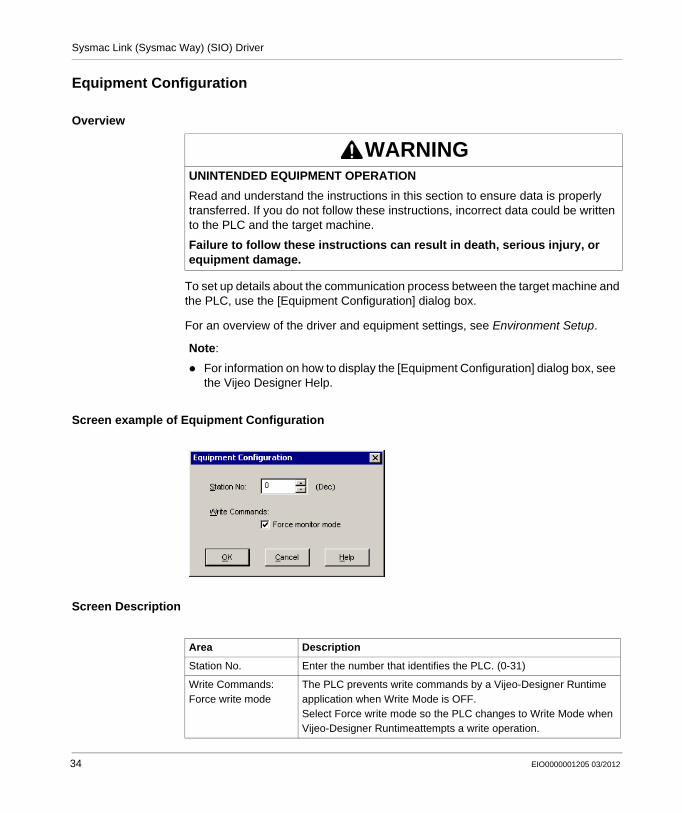
Equipment Configuration
Overview
To set up details about the communication process between the target machine and the PLC, use the [Equipment Configuration] dialog box.
For an overview of the driver and equipment settings, see Environment Setup.
Screen example of Equipment Configuration
Screen Description
WARNINGUNINTENDED EQUIPMENT OPERATIONRead and understand the instructions in this section to ensure data is properly transferred. If you do not follow these instructions, incorrect data could be written to the PLC and the target machine.
Failure to follow these instructions can result in death, serious injury, or equipment damage.
Note:
For information on how to display the [Equipment Configuration] dialog box, see the Vijeo Designer Help.
Area Description
Station No. Enter the number that identifies the PLC. (0-31)
Write Commands: Force write mode
The PLC prevents write commands by a Vijeo-Designer Runtime application when Write Mode is OFF.Select Force write mode so the PLC changes to Write Mode when Vijeo-Designer Runtimeattempts a write operation.
34 EIO0000001205 03/2012

Sysmac Link (Sysmac Way) (SIO) Driver
Device Address Configuration
Overview
To set up a PLC variable in the Variable List, use the Device Address Keypad from the variable properties.
See Supported Device Addresses.
Screen example of Device Address Keypad
WARNINGUNINTENDED EQUIPMENT OPERATIONRead and understand the instructions in this section to ensure data is properly transferred. If you do not follow these instructions, incorrect data could be written to the PLC and the target machine.
Failure to follow these instructions can result in death, serious injury, or equipment damage.
Note:
For information on how to display the Device Address Keypad, see the Vijeo Designer Help.
EIO0000001205 03/2012 35

Sysmac Link (Sysmac Way) (SIO) Driver
Screen Description
Area Description
Device Lists the PLC’s discrete and word device types.
Address Enter the device address for the PLC variable. The keypad ensures that you enter the correct format for bit and word devices.
36 EIO0000001205 03/2012


![Corp Govn[1]. 14 03 2009](https://img.dokumen.tips/doc/110x75/577d39991a28ab3a6b9a273b/corp-govn1-14-03-2009.jpg)