Embed Size (px)
Citation preview

Eindhoven University of Technology
MASTER
Peer-to-peer multimedia streaming monitoring system
Wang, Z.
Award date:2014
Link to publication
DisclaimerThis document contains a student thesis (bachelor's or master's), as authored by a student at Eindhoven University of Technology. Studenttheses are made available in the TU/e repository upon obtaining the required degree. The grade received is not published on the documentas presented in the repository. The required complexity or quality of research of student theses may vary by program, and the requiredminimum study period may vary in duration.
General rightsCopyright and moral rights for the publications made accessible in the public portal are retained by the authors and/or other copyright ownersand it is a condition of accessing publications that users recognise and abide by the legal requirements associated with these rights.
• Users may download and print one copy of any publication from the public portal for the purpose of private study or research. • You may not further distribute the material or use it for any profit-making activity or commercial gain
Peer-to-Peer multimediastreaming monitoring
system
Master Thesis
Zijian Wang
Department of Mathematics and Computer ScienceArchitecture of Information Systems Research Group
Supervisor:dr. Dmitri Jarnikov
Eindhoven, August 2014


Abstract
Nowadays, many companies provide on-demand or live multimedia content over the Internet. Thesuccess of the content provider is measured by the number of subscribers. There are, however,pirates that re-distribute obtained content illegally, thus cutting into the legitimate subscribersbase. The content providers would like to know how serious the problem is in order to address it.The goal of our project is to develop a monitoring system to help the content provider to learn:what is the popularity of the pirated content, who is using the illegal service, and where are theillegal users?
Our system focuses on services that are based on P2P streaming technology because its cost-effectiveness and scalability advantages are appealing to pirates. We aim to develop a systemthat can monitor an arbitrary P2P streaming system. To achieve this goal we will address thefollowing questions in our project: How to perform analysis to understand the audience? Whatmeasurement data can we collect? How to measure a high-dynamic P2P network? How to gatherdata from an arbitrary (and proprietary) P2P streaming application?
In the end, we present a distributed monitoring system based on passive measurement. Weconducted a set of evaluation experiments on three popular and representative P2P streamingsystems: Acestream, Sopcast and Peerflix. The evaluation results proved the effectiveness of ourmeasurement approach and strategy.
Peer-to-Peer multimedia streaming monitoring system iii


Preface
Six months ago, I started my master project. During the last half year I contributedall myself to solving the problem, using the best of my knowledge. It was a enjoyableperiod of time and this thesis is the statement of my achievements. I hope you enjoyreading. I wish to thank my parents and my girlfriend. Without their support and loveI cannot finish this work. I also wish to thank my supervisor, dr. Jarnikov, who gaveme innumerable guidance and help during my project.
Peer-to-Peer multimedia streaming monitoring system v

Contents
Contents vii
List of Figures ix
List of Tables xi
1 Introduction 11.1 Problem statement . . . . . . . . . . . . . . . . . . . . . . . . . . . . . . . . . . . . 11.2 Internet multimedia delivery . . . . . . . . . . . . . . . . . . . . . . . . . . . . . . . 11.3 Approach . . . . . . . . . . . . . . . . . . . . . . . . . . . . . . . . . . . . . . . . . 2
1.3.1 Measurement . . . . . . . . . . . . . . . . . . . . . . . . . . . . . . . . . . . 21.3.2 Analysis . . . . . . . . . . . . . . . . . . . . . . . . . . . . . . . . . . . . . . 3
1.4 Thesis outline . . . . . . . . . . . . . . . . . . . . . . . . . . . . . . . . . . . . . . . 4
2 Domain analysis 52.1 Internet multimedia delivery technologies . . . . . . . . . . . . . . . . . . . . . . . 52.2 Selected system . . . . . . . . . . . . . . . . . . . . . . . . . . . . . . . . . . . . . . 6
2.2.1 P2P streaming architecture overview . . . . . . . . . . . . . . . . . . . . . . 62.2.2 Generic architecture . . . . . . . . . . . . . . . . . . . . . . . . . . . . . . . 6
2.3 Related work . . . . . . . . . . . . . . . . . . . . . . . . . . . . . . . . . . . . . . . 8
3 Solution and implementation 113.1 System description . . . . . . . . . . . . . . . . . . . . . . . . . . . . . . . . . . . . 113.2 Methodology . . . . . . . . . . . . . . . . . . . . . . . . . . . . . . . . . . . . . . . 11
3.2.1 Measurement . . . . . . . . . . . . . . . . . . . . . . . . . . . . . . . . . . . 113.2.2 Analysis . . . . . . . . . . . . . . . . . . . . . . . . . . . . . . . . . . . . . . 123.2.3 Report . . . . . . . . . . . . . . . . . . . . . . . . . . . . . . . . . . . . . . . 13
3.3 System overview . . . . . . . . . . . . . . . . . . . . . . . . . . . . . . . . . . . . . 133.4 System design . . . . . . . . . . . . . . . . . . . . . . . . . . . . . . . . . . . . . . . 15
3.4.1 Monitor . . . . . . . . . . . . . . . . . . . . . . . . . . . . . . . . . . . . . . 153.4.2 Master . . . . . . . . . . . . . . . . . . . . . . . . . . . . . . . . . . . . . . . 183.4.3 Manager . . . . . . . . . . . . . . . . . . . . . . . . . . . . . . . . . . . . . . 193.4.4 Analyser . . . . . . . . . . . . . . . . . . . . . . . . . . . . . . . . . . . . . . 203.4.5 Storage . . . . . . . . . . . . . . . . . . . . . . . . . . . . . . . . . . . . . . 20
4 Evaluation 224.1 Measurement . . . . . . . . . . . . . . . . . . . . . . . . . . . . . . . . . . . . . . . 23
4.1.1 Distributed experiment . . . . . . . . . . . . . . . . . . . . . . . . . . . . . 234.1.2 Unsupervised choking experiment . . . . . . . . . . . . . . . . . . . . . . . . 234.1.3 Supervised choking experiment . . . . . . . . . . . . . . . . . . . . . . . . . 264.1.4 Dynamic assignment experiment . . . . . . . . . . . . . . . . . . . . . . . . 26
4.2 Viewer detection . . . . . . . . . . . . . . . . . . . . . . . . . . . . . . . . . . . . . 30
Peer-to-Peer multimedia streaming monitoring system vii
CONTENTS
5 Conclusions 31
Bibliography 33
Appendix 39
A Internet multimedia delivery technology characteristics 39A.1 Service type . . . . . . . . . . . . . . . . . . . . . . . . . . . . . . . . . . . . . . . . 39A.2 Content formats . . . . . . . . . . . . . . . . . . . . . . . . . . . . . . . . . . . . . 39A.3 Delivery method . . . . . . . . . . . . . . . . . . . . . . . . . . . . . . . . . . . . . 40A.4 Network protocols . . . . . . . . . . . . . . . . . . . . . . . . . . . . . . . . . . . . 42
A.4.1 Transport protocols . . . . . . . . . . . . . . . . . . . . . . . . . . . . . . . 42A.4.2 Application protocols . . . . . . . . . . . . . . . . . . . . . . . . . . . . . . 42
A.5 Network architecture . . . . . . . . . . . . . . . . . . . . . . . . . . . . . . . . . . . 44A.6 Client software composition . . . . . . . . . . . . . . . . . . . . . . . . . . . . . . . 45
B P2P streaming system architecture 47B.1 Mesh-based architecture . . . . . . . . . . . . . . . . . . . . . . . . . . . . . . . . . 47B.2 Tree-based architecture . . . . . . . . . . . . . . . . . . . . . . . . . . . . . . . . . 48
C Use case diagram of monitoring system 51
D Configuration specification 53
viii Peer-to-Peer multimedia streaming monitoring system
List of Figures
1.1 Value chain of Internet multimedia market . . . . . . . . . . . . . . . . . . . . . . . 21.2 Passive measurement principle . . . . . . . . . . . . . . . . . . . . . . . . . . . . . 3
2.1 Characteristics of Internet multimedia delivery technology . . . . . . . . . . . . . . 52.2 P2P streaming system generic architecture . . . . . . . . . . . . . . . . . . . . . . . 7
3.1 Work process of monitoring system . . . . . . . . . . . . . . . . . . . . . . . . . . . 113.2 Report tool output example . . . . . . . . . . . . . . . . . . . . . . . . . . . . . . . 133.3 P2P streaming monitoring system overall architecture . . . . . . . . . . . . . . . . 143.4 Message diagram of monitor . . . . . . . . . . . . . . . . . . . . . . . . . . . . . . . 153.5 Work process of the packet capture . . . . . . . . . . . . . . . . . . . . . . . . . . . 163.6 Flow updating process of reporter . . . . . . . . . . . . . . . . . . . . . . . . . . . 183.7 Message diagram of master with 3 monitors . . . . . . . . . . . . . . . . . . . . . . 193.8 Message diagram of manager with 2 masters . . . . . . . . . . . . . . . . . . . . . . 20
4.1 Distributed experiment on Acestream . . . . . . . . . . . . . . . . . . . . . . . . . 234.2 Distributed experiment on Peerflix . . . . . . . . . . . . . . . . . . . . . . . . . . . 244.3 Unsupervised choking experiment on Acestream . . . . . . . . . . . . . . . . . . . . 244.4 Unsupervised choking experiment on Peerflix . . . . . . . . . . . . . . . . . . . . . 254.5 Unsupervised choking experiment on Sopcast . . . . . . . . . . . . . . . . . . . . . 254.6 Supervised choking experiment on Acestream, number of observed peers . . . . . . 264.7 Supervised choking experiment on Acestream, overlapping ratio . . . . . . . . . . . 274.8 Supervised choking experiment on Peerflix, number of observed peers . . . . . . . . 274.9 Supervised choking experiment on Peerflix, overlapping ratio . . . . . . . . . . . . 284.10 Dynamic monitor assignment experiment on Acestream . . . . . . . . . . . . . . . 294.11 Dynamic monitor assignment experiment on Peerflix . . . . . . . . . . . . . . . . . 29
5.1 Principle of multi-client support . . . . . . . . . . . . . . . . . . . . . . . . . . . . . 32
B.1 Mesh-pull P2P streaming architecture . . . . . . . . . . . . . . . . . . . . . . . . . 47B.2 Tree-push P2P streaming architecture . . . . . . . . . . . . . . . . . . . . . . . . . 49
C.1 System use case diagram . . . . . . . . . . . . . . . . . . . . . . . . . . . . . . . . . 51
Peer-to-Peer multimedia streaming monitoring system ix

List of Tables
3.1 Storage design . . . . . . . . . . . . . . . . . . . . . . . . . . . . . . . . . . . . . . 21
4.1 Comparison of target P2P streaming systems . . . . . . . . . . . . . . . . . . . . . 224.2 Viewer detection experiment . . . . . . . . . . . . . . . . . . . . . . . . . . . . . . 30
Peer-to-Peer multimedia streaming monitoring system xi

Chapter 1
Introduction
1.1 Problem statement
In the market of Internet multimedia, there are content providers offering on-demand or livecontent to their audience. For example, Sky Sports aggregates games from sport leagues all overthe world and provides live broadcasting to its audience; Netflix offers its subscribers movies andTV series online, which is its own production (e.g. House of Cards) or bought from other contentproviders. However, there are illegal services (i.e. pirates) pirating these content. These piratesreceive content from a content provider as normal viewers, and re-distribute the content to otherviewers illegally. The content providers’ earnings are harmed, they are interested to know howserious the piracy problem is in order to address it. They ask questions such as:
• What content is being distributed by the illegal services?
• What is the audience of these services (e.g. location, scale etc.)?
The first problem is related to crawling techniques. Moshchuk et al. proposed a crawler thatcan be used to search pirated contents on Web [52]. Work of Indyk et al. is more specific [34],because it aims to crawl pirated video content. Since the problem of searching pirated contentcan be solved by crawling techniques, it is not in the scope of our project.
The focus of our project is placed on the second problem-illegal service audience measurementand analysis. We want to develop a monitoring system that can help content providers understandthe extent of the piracy of their content. To achieve this goal, we need first answer the followingquestions by ourselves:
• What Internet multimedia delivery systems exist? And which are popular?
• What system do we want to investigate?
• How to collect and analyse data from the selected system?
We discuss these questions in the following sections. In Section 2, we introduce the Internetmultimedia delivery from both business and technical perspectives. In Section 3 we propose ourapproaches of measurement and analysis.
1.2 Internet multimedia delivery
The Internet is a powerful platform for content delivery services. Multimedia content is the mostprevalent content on the Internet [36]. Its popularity is not a new phenomenon, and the roll-outof the broadband Internet access has accelerated that. The large demand for multimedia contentbrings great opportunities to companies. In order to understand this market, we present a business
Peer-to-Peer multimedia streaming monitoring system 1
CHAPTER 1. INTRODUCTION
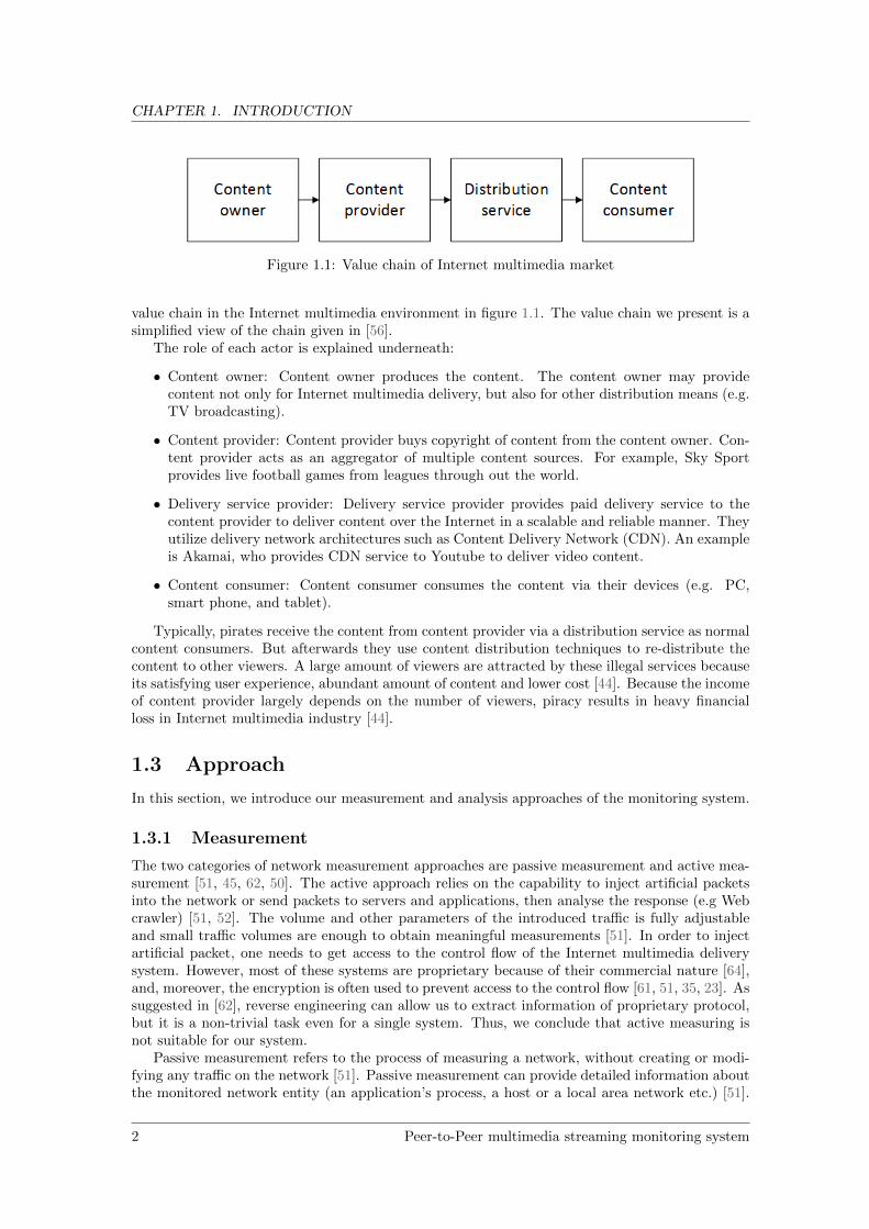
Figure 1.1: Value chain of Internet multimedia market
value chain in the Internet multimedia environment in figure 1.1. The value chain we present is asimplified view of the chain given in [56].
The role of each actor is explained underneath:
• Content owner: Content owner produces the content. The content owner may providecontent not only for Internet multimedia delivery, but also for other distribution means (e.g.TV broadcasting).
• Content provider: Content provider buys copyright of content from the content owner. Con-tent provider acts as an aggregator of multiple content sources. For example, Sky Sportprovides live football games from leagues through out the world.
• Delivery service provider: Delivery service provider provides paid delivery service to thecontent provider to deliver content over the Internet in a scalable and reliable manner. Theyutilize delivery network architectures such as Content Delivery Network (CDN). An exampleis Akamai, who provides CDN service to Youtube to deliver video content.
• Content consumer: Content consumer consumes the content via their devices (e.g. PC,smart phone, and tablet).
Typically, pirates receive the content from content provider via a distribution service as normalcontent consumers. But afterwards they use content distribution techniques to re-distribute thecontent to other viewers. A large amount of viewers are attracted by these illegal services becauseits satisfying user experience, abundant amount of content and lower cost [44]. Because the incomeof content provider largely depends on the number of viewers, piracy results in heavy financialloss in Internet multimedia industry [44].
1.3 Approach
In this section, we introduce our measurement and analysis approaches of the monitoring system.
1.3.1 Measurement
The two categories of network measurement approaches are passive measurement and active mea-surement [51, 45, 62, 50]. The active approach relies on the capability to inject artificial packetsinto the network or send packets to servers and applications, then analyse the response (e.g Webcrawler) [51, 52]. The volume and other parameters of the introduced traffic is fully adjustableand small traffic volumes are enough to obtain meaningful measurements [51]. In order to injectartificial packet, one needs to get access to the control flow of the Internet multimedia deliverysystem. However, most of these systems are proprietary because of their commercial nature [64],and, moreover, the encryption is often used to prevent access to the control flow [61, 51, 35, 23]. Assuggested in [62], reverse engineering can allow us to extract information of proprietary protocol,but it is a non-trivial task even for a single system. Thus, we conclude that active measuring isnot suitable for our system.
Passive measurement refers to the process of measuring a network, without creating or modi-fying any traffic on the network [51]. Passive measurement can provide detailed information aboutthe monitored network entity (an application’s process, a host or a local area network etc.) [51].
2 Peer-to-Peer multimedia streaming monitoring system
CHAPTER 1. INTRODUCTION
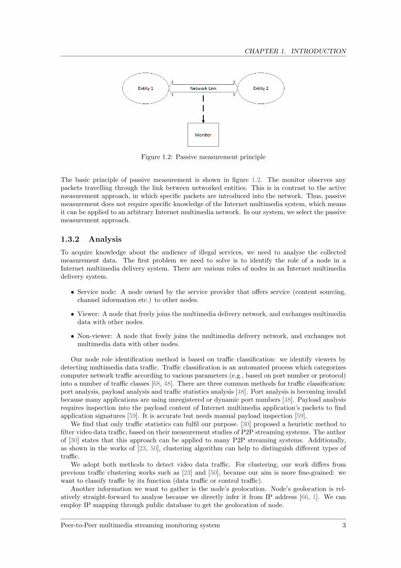
Figure 1.2: Passive measurement principle
The basic principle of passive measurement is shown in figure 1.2. The monitor observes anypackets travelling through the link between networked entities. This is in contrast to the activemeasurement approach, in which specific packets are introduced into the network. Thus, passivemeasurement does not require specific knowledge of the Internet multimedia system, which meansit can be applied to an arbitrary Internet multimedia network. In our system, we select the passivemeasurement approach.
1.3.2 Analysis
To acquire knowledge about the audience of illegal services, we need to analyse the collectedmeasurement data. The first problem we need to solve is to identify the role of a node in aInternet multimedia delivery system. There are various roles of nodes in an Internet multimediadelivery system.
• Service node: A node owned by the service provider that offers service (content sourcing,channel information etc.) to other nodes.
• Viewer: A node that freely joins the multimedia delivery network, and exchanges multimediadata with other nodes.
• Non-viewer: A node that freely joins the multimedia delivery network, and exchanges notmultimedia data with other nodes.
Our node role identification method is based on traffic classification: we identify viewers bydetecting multimedia data traffic. Traffic classification is an automated process which categorizescomputer network traffic according to various parameters (e.g., based on port number or protocol)into a number of traffic classes [68, 48]. There are three common methods for traffic classification:port analysis, payload analysis and traffic statistics analysis [48]. Port analysis is becoming invalidbecause many applications are using unregistered or dynamic port numbers [48]. Payload analysisrequires inspection into the payload content of Internet multimedia application’s packets to findapplication signatures [59]. It is accurate but needs manual payload inspection [59].
We find that only traffic statistics can fulfil our purpose. [30] proposed a heuristic method tofilter video data traffic, based on their measurement studies of P2P streaming systems. The authorof [30] states that this approach can be applied to many P2P streaming systems. Additionally,as shown in the works of [23, 50], clustering algorithm can help to distinguish different types oftraffic.
We adopt both methods to detect video data traffic. For clustering, our work differs fromprevious traffic clustering works such as [23] and [50], because our aim is more fine-grained: wewant to classify traffic by its function (data traffic or control traffic).
Another information we want to gather is the node’s geolocation. Node’s geolocation is rel-atively straight-forward to analyse because we directly infer it from IP address [66, 1]. We canemploy IP mapping through public database to get the geolocation of node.
Peer-to-Peer multimedia streaming monitoring system 3
CHAPTER 1. INTRODUCTION
1.4 Thesis outline
The structure of the thesis is as follows:
• Chapter 2 introduces the Internet multimedia delivery technology.
• Chapter 3 proposes the solution and implementation details.
• Chapter 4 shows the evaluation result and analysis.
• Chapter 5 presents the future work and conclusions.
4 Peer-to-Peer multimedia streaming monitoring system
Chapter 2
Domain analysis
The aim of this chapter is to introduce the technical background of our project. We want tointroduce how multimedia content is distributed (by pirates) over the Internet and explain whyour focus is on P2P streaming systems.
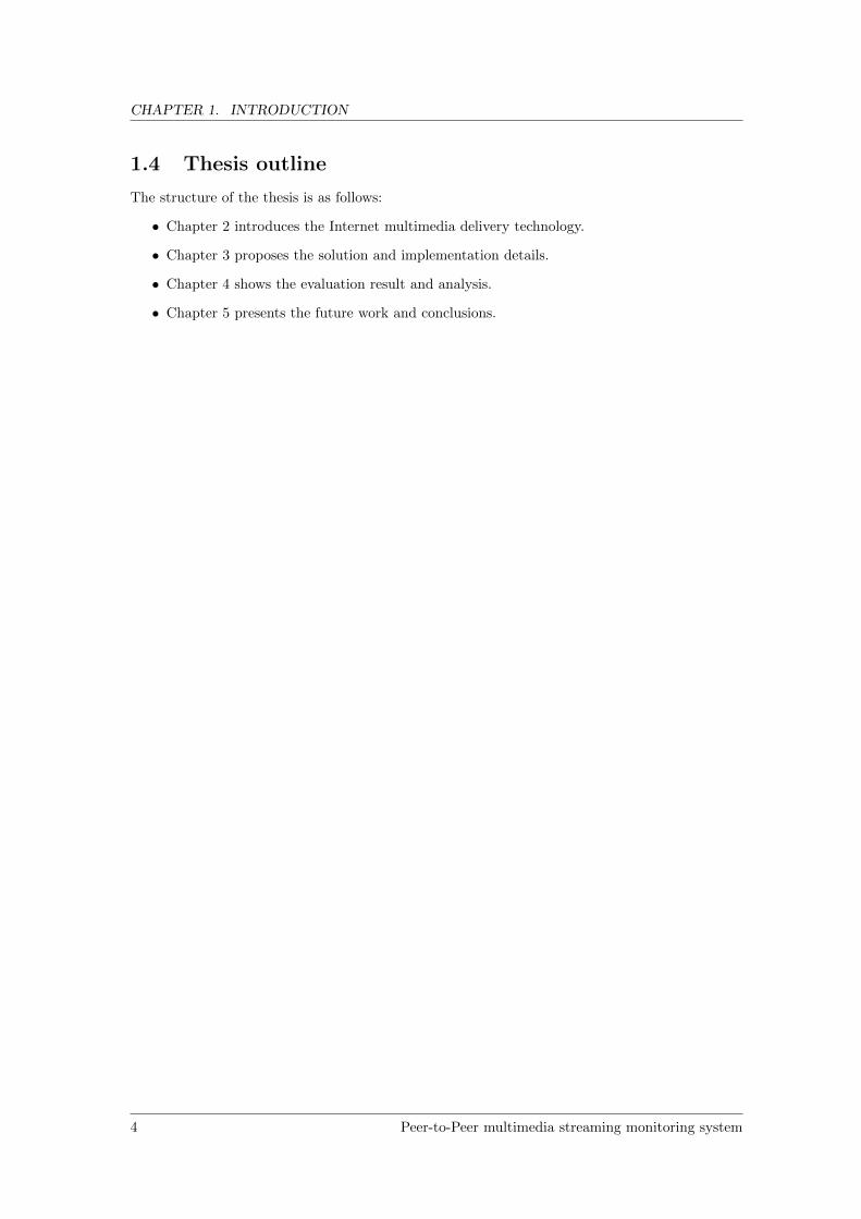
2.1 Internet multimedia delivery technologies
To understand how pirates are distributing the multimedia content, we discuss characteristics ofInternet multimedia delivery technologies. Each characteristic of 2.1 is explained in Appendix A.
The multimedia services can be classified into two groups: live streaming and video-on-demand(VoD) [47, 41]. Straight download is also considered for historical reasons. To serve thevideo content, the raw video must be compressed before transmission because of its huge size [67].Once the raw video is compressed, it needs to be packaged into a container. Different systems varyin their support of compression format and container format. Delivery method deals with how themultimedia file is delivered to the end-user. While streaming is the mainstream delivery method,other options exist as well. Protocols are designed and standardized for communication betweenclients and streaming servers [67]. In the characteristics we discuss both standard protocols andproprietary ones. Network architecture deals with how the content is delivered over the network.And, the client software part describes how content data is received and played out to the user.
Figure 2.1: Characteristics of Internet multimedia delivery technology
Peer-to-Peer multimedia streaming monitoring system 5

CHAPTER 2. DOMAIN ANALYSIS
2.2 Selected system
Based on our study, we find that P2P streaming technology is the most appealing one to the illegalservice providers because of its two advantages: cost-effectiveness and scalability. P2P networksdo not rely on a dedicated delivery infrastructure and therefore offer the possibility of rapiddeployment at low cost. The upload capacity of hosts in a P2P network can be utilized for videotransmission so as to reduce the server load dramatically, which offers great scalability. Studiesof [44, 27, 31] also confirm that P2P streaming systems appear to be the most used mechanismfor Internet multimedia delivery.
In the remainder of the thesis, we focus on developing a monitoring solution for P2P streamingsystems.
2.2.1 P2P streaming architecture overview
P2P streaming, as its name suggests, is a technology utilizing P2P network for multimedia stream-ing service [70, 43]. In P2P streaming system, the video file is segmented into small pieces (calledchunks) and sent to hosts (called peers) in the P2P streaming network. Peers actively contributetheir resources by forwarding available content to other peers. By this approach, the availableamount of content grows with the size of network [43].
Although P2P streaming netowrk has advantages for serving massive number of viewers, how-ever, it is also challenging to design a P2P streaming system because of the stringent time con-strains and hosts’ diverse capacity (e.g. upload bandwidth) [18, 28]. To address these challenges,many systems have been designed [73, 49, 31, 6, 7].
By logical overlay topology classification, P2P streaming systems are roughly classified into twotypes; tree-based and mesh-based [32, 31, 70, 42]. Detailed study of mesh-based and tree-basedarchitecture is in Appendix B. In tree-based architectures, nodes make tree shaped connectionsand contents are transmitted from root to leaf by overlay multicast. Tree-based architectureshave well-organized overlay structure, which makes it has lower delays between a distributorand nodes. One major drawback of tree-based is that they are vulnerable to peers’ departures.On the other hand, in mesh-based architectures, such as Coolstreaming [73], peers construct anoverlay network without making clear hierarchy. In a mesh-based P2P streaming system, peersare not confined to a static topology, instead, peering relationships are established/terminatedbased on the content availability and bandwidth availability on peers [49]. A peer dynamicallyconnects to a subset of peers in a swarm and pulls chunks from each other. Its major advantageis its simple design principle and inherent robustness. However, the delay performance in mesh-based cannot be guaranteed [43]. As stated in [31], mesh-based P2P streaming systems havebeen successfully deployed in commercial area. In contrast, tree-based systems largely have beenrunning at the research stage. Study from [49] shows that mesh-based architecture exhibits asuperior performance across a wide range of of scenarios. In our work, we focus on mesh-basedarchitecture.
2.2.2 Generic architecture
We can separate the actions of P2P streaming system into two tasks: overlay construction andpeer communication, which is similar with the discussion in [31, 49]. Overlay construction dealswith how to construct an efficient and resilient architecture of a P2P streaming network; peercommunication deals with how to efficiently distribute video chunks through the established overlayarchitecture. In addition, based on the peer’s communication behaviour, we generalized four rolesof peers in a P2P streaming architecture. We present a generic architecture of P2P streamingsystem as shown in figure 2.2. The elements on the architecture are discussed in the followingsubsections.
6 Peer-to-Peer multimedia streaming monitoring system

CHAPTER 2. DOMAIN ANALYSIS
Figure 2.2: P2P streaming system generic architecture
Overlay construction
Overlay construction’s purpose is to help a peer construct its neighbour relationship with otherpeers [31]. The efficiency of a P2P streaming network relies a lot on its overlay structure. In a P2Pstreaming architecture, an overlay swarm is formed by peers viewing the same content [49, 70]. Inboth mesh-based an tree-based systems, the media stream is transmitted from a source peer to allparticipating peers. However as shown in figures B.1 and B.2, in tree-based system there existsonly one path from source peer to any other peer; in mesh-based topology there are multiple paths.We can break overlay construction into two sub issues: peer discovery and peer selection [28].
The purpose of peer discovery is to find information about other peers in the P2P streamingnetwork [37]. There are two general peer-discovery approaches: centralized and decentralized.In centralized approach, a central node maintains the global peer information (e.g. a trackernode) [70]. It is the most commonly used method for locating peers, which has, unfortunately, theproblem of single-point-failure [70]. In decentralized approach, each peer maintains a subset of theoverlay information. If a peer wants to discover other peers, it has two methods: flooding methodand gossip method [28]. In flooding method, a peer sends a probe message first to a starting peer,and then to its neighbours and their neighbours until finally finding a suitable point to join thenetwork. In networks using the gossip-based method, a peer maintains information about a smalllist of randomly selected peers, initially obtained from a starting peer, and information is updatedperiodically by exchanging messages with other peers in the list [28].
Peer selection deals with how a peer construct its neighbour relationship. As stated in [57], agood peer selection algorithm should achieve the following goals: 1) minimizing packet delay; 2)achieving a minimum of total streaming rate at a peer; 3) being more resilient to peer and networkdynamics. A key issue for peer selection is to measure peer’s network connectivity [57]. Currently,the two common methods are: by measuring packet delay and by estimating bandwidth [28].
In studies of [49, 43, 70], we find that for overlay construction the network connectivity isan essential influencing factor. In tree-based architecture the bandwidth of a peer determinesits place in the tree structure. In mesh-based, the upload capacity plays a major role in peerselection [43, 60], as well. A higher priority is assigned (dynamically) to peers that upload moredata. This observation on network connectivity is important for our lately proposed approach.
Another observation is that, a peer tries to construct its neighbour relationship with otherpeers to exchange data in the most efficient way, which implicates that a peer only contact a
Peer-to-Peer multimedia streaming monitoring system 7

CHAPTER 2. DOMAIN ANALYSIS
limited number of peers .
Peer communication
Tree-based architecture and mesh-based architecture differ in their chunk delivery behaviour. Inmesh-based based, the video chunks are actively requested from other neighbour peers, and for apeer its neighbour relationship is dynamically changing. The amount of control traffic overheadfor requesting and responding chunk is not negligible. In comparison, in tree-based architecture,video chunks are passively received from parent peers in a tree overlay, which means there is verysmall control overhead for chunk delivery.
Although two architectures exhibit different peer communication behaviours, we can generalizetheir commons. The peer’s communication flow can be classified into two classes: control flowand data flow [18, 22] (a flow is a sequence of packets between two hosts [22]). Control flow isused to exchange control information (e.g. peer discovery, peer selection, chunk request). Dataflow is composed of packets carrying data chunks and control information overhead. Based on theclassification of peer’s traffic characteristics, we define generic roles of peers in a P2P streamingnetwork (from a local peer’s perspective):
• Tracker: A node owned by service provider that provides overlay information to peers frommultiple events’ overlays. The tracker only has control flow. In a system, tracker is anoptional node.
• Injection node: A peer owned by service provider that provides data as a source. Injectionnode only have data flow. Moreover, it has large amount of upload traffic and almost nodownload traffic. The injection node may provide uploads to multiple events (i.e. participatein distribution of different data simultaneously).
• Viewer: A peer that freely joins the P2P network, and exchanges data chunks with otherpeers in its overlay swarm. It has control and data flow. Its ratio of upload traffic anddownload traffic is not definable.
– Neighbour: Same as viewer, but a neighbour peer has direct data exchange with thelocal peer.
• Non-viewer: A peer that freely joins the P2P network, and does not exchange data chunkswith other peers. A non-viewer does not participate in the local peer’s overlay.
The requirement on our P2P streaming monitoring system is to support measurement andanalysis of the audience of a P2P streaming system. To be specific, we need to detect viewerpeers in a P2P streaming network. From the peer role category above, we find the data traffic isan important clue in distinguishing viewers and non-viewers, which is the reason we adopt trafficstatistic analysis.
2.3 Related work
There have been many measurement studies on P2P multimedia streaming systems [61, 20, 18,26, 62, 30]. All of them focus on certain systems(e.g. PPlive, Sopcast, PPstream etc.) andcertain characteristics, but none of them focus on the monitoring system’s architecture for anarbitrary P2P streaming system. A very similar work with ours is NG-MON [29], which is also adistributed network monitoring system that adopts passive measurement approach. But NG-MONis not specific for P2P streaming system. Comparably, we proposed a system architecture thatsupports dynamic resource allocation, and we utilize the properties of P2P network to improvethe measurement performance.
For traffic analysis, we use the heuristic of data flow proposed by [30]. In addition, we also usea machine learning method. [23, 50, 72] laid foundation of utilizing machine learning for traffic
8 Peer-to-Peer multimedia streaming monitoring system

CHAPTER 2. DOMAIN ANALYSIS
analysis. However, all of them use clustering algorithm to classify traffic by type (e.g. P2P,Web, File transfering) or by application type. In comparison, our goal of analysis is more fine-grained: we want to classify traffic by its function (data traffic or control traffic). The work fromPark et al. [54] and ours both work on fine-grained P2P traffic classification [54]. However, theyuse payload signature retrieval technique, whereas we use clustering algorithm to analyse trafficstatistics.
Peer-to-Peer multimedia streaming monitoring system 9

Chapter 3
Solution and implementation
This chapter presents the solution of our P2P streaming monitoring system.
3.1 System description
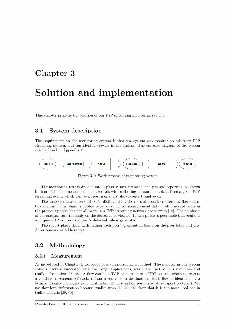
The requirement on the monitoring system is that the system can monitor an arbitrary P2Pstreaming system, and can identify viewers in the system. The use case diagram of the systemcan be found in Appendix C.
Figure 3.1: Work process of monitoring system
The monitoring task is divided into 3 phases: measurement, analysis and reporting, as shownin figure 3.1. The measurement phase deals with collecting measurement data from a given P2Pstreaming event, which can be a sport game, TV show, concert, and so on.
The analysis phase is responsible for distinguishing the roles of peers by performing flow statis-tics analysis. This phase is needed because we collect measurement data of all observed peers inthe previous phase, but not all peers in a P2P streaming network are viewers [19]. The emphasisof our analysis task is mainly on the detection of viewers. In this phase, a peer table that containseach peer’s IP address and peer’s detected role is generated.
The report phase deals with finding each peer’s geolocation based on the peer table and pro-duces human-readable report.
3.2 Methodology
3.2.1 Measurement
As introduced in Chapter 1, we adopt passive measurement method. The monitor in our systemcollects packets associated with the target applications, which are used to construct flow-leveltraffic information [38, 68]. A flow can be a TCP connection or a UDP stream, which representsa continuous sequence of packets from a source to a destination. Each flow is identified by a5-tuple: (source IP, source port, destination IP, destination port, type of transport protocol). Weuse flow-level information because studies from [72, 23, 29] show that it is the most used one intraffic analysis [29, 68].
Peer-to-Peer multimedia streaming monitoring system 11

CHAPTER 3. SOLUTION AND IMPLEMENTATION
3.2.2 Analysis
We propose a viewer detection method by analysing video data traffic. Currently, there arethree types of traffic classification methods: port analysis, payload analysis, and flow statisticsanalysis [48, 68].
• Port analysis: this method depends on mapping of well-known port numbers to protocols.For example, the packet with destination port 80 is classified as HTTP traffic. This methodis highly efficient if we can map port to known applications or protocols. However, thismethod is becoming less effective due to the fact that some applications allocate dynamicports, which is often the case for P2P applications [48].
• Payload analysis: this method relies on the knowledge about the payload formats for Internetapplications. Study of [59] shows that the payload-based analysis is accurate. However,encryption makes this method less practical [68]. And most of P2P streaming systems useproprietary protocols, which are often encrypted. This method is not applicable for oursystem.
• Flow statistics analysis: Flow statistics analysis maps instances of network traffic flow intodifferent classes based on flow’s statistics. A flow is described by a set of statistical featuresand associated feature values. A feature is a descriptive statistic (e.g average packet size,duration) that can be calculated from one or more packets. Some measurement studies usea heuristic filtering method to classify flows [30, 61]. Machine-learning is also a widely usedapproach for flow statistics analysis [23, 50].
From above, wed find that only flow statistics analysis can fulfil our goal. We adopted bothheuristic filtering and machine learning approaches.
Heuristic filtering
The authors of [30] use this method to isolate video data traffic. The heuristic is based on theirmeasurement studies on many P2P streaming systems. They found that if in a flow more than10 large packets (> 1000 bytes) are found, this flow is a video data flow [30, 61]. The authorsof [30] state that heuristic method can also be applied to other P2P streaming systems. We usethis approach to detect data flow.
K-means clustering
As shown in [23, 50], machine learning can help to distinguish different types of traffic. Machinelearning falls into two categories: supervised and unsupervised [23, 50].
• Supervised machine learning: It is also known as classification. The goal of classification is tobuild a classification model of the distribution of class labels in terms of predictor features.The resulting classifier is then used to assign class labels to the new instances where thevalues of the predictor features are known, but the value of the class label is unknown.
• Unsupervised machine learning: It is also known as clustering. Clustering is the partitioningof objects into disjoint groups, referred as clusters, such that objects within a group aresimilar according to chosen criteria [23, 50]. There are many popular algorithms: K-Means,AutoClass, DBSCAN , which vary in speed and accuracy.
Supervised learning produces a model that fits the training data, where the training data isa priori available [23]. The training data is a collection of instances with known label values (in-stance’s class). In contrast, unsupervised learning uses unlabelled training data to find similaritiesor patterns among objects in the data set. As our target is to monitor proprietary P2P streaming
12 Peer-to-Peer multimedia streaming monitoring system
CHAPTER 3. SOLUTION AND IMPLEMENTATION
systems, there is no ground truth of the traffic we measured [64, 50]. Because of the lack of la-belled data, unsupervised machine learning is the only applicable machine learning approach forour system.
We use K-means algorithm since it is one of the quickest and simplest clustering algorithm [50].K-means clustering has been shown having good performance in traffic classification in [23]. K-means clustering aims to partition instances into K clusters in which each observation belongs tothe cluster with the nearest mean, serving as a prototype of the cluster. In our system, we selectthe average size of packets as the flow feature for clustering.
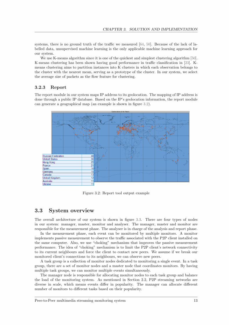
3.2.3 Report
The report module in our system maps IP address to its geolocation. The mapping of IP address isdone through a public IP database. Based on the IP’s geolocation information, the report modulecan generate a geographical map (an example is shown in figure 3.2).
Figure 3.2: Report tool output example
3.3 System overview
The overall architecture of our system is shown in figure 3.3. There are four types of nodesin our system: manager, master, monitor and analyser. The manager, master and monitor areresponsible for the measurement phase. The analyser is in charge of the analysis and report phase.
In the measurement phase, each event can be monitored by multiple monitors. A monitorimplements passive measurement to observe the traffic associated with the P2P client installed onthe same computer. Also, we use “choking” mechanism that improves the passive measurementperformance. The idea of “choking” mechanism is to limit the P2P client’s network connectivityto its current neighbours and force the client to contact new peers. We assume if we break ourmonitored client’s connections to its neighbours, we can observe new peers.
A task group is a collection of monitor nodes dedicated to monitoring a single event. In a taskgroup, there are a set of monitor nodes and a master node that coordinates monitors. By havingmultiple task groups, we can monitor multiple events simultaneously.
The manager node is responsible for allocating monitor nodes to each task group and balancethe load of the monitoring system. As mentioned in Section 2.2, P2P streaming networks arediverse in scale, which means events differ in popularity. The manager can allocate differentnumber of monitors to different tasks based on their popularity.
Peer-to-Peer multimedia streaming monitoring system 13

CHAPTER 3. SOLUTION AND IMPLEMENTATION
Figure 3.3: P2P streaming monitoring system overall architecture
In the next section, we introduce each of these components in detail.
14 Peer-to-Peer multimedia streaming monitoring system
CHAPTER 3. SOLUTION AND IMPLEMENTATION
3.4 System design
3.4.1 Monitor
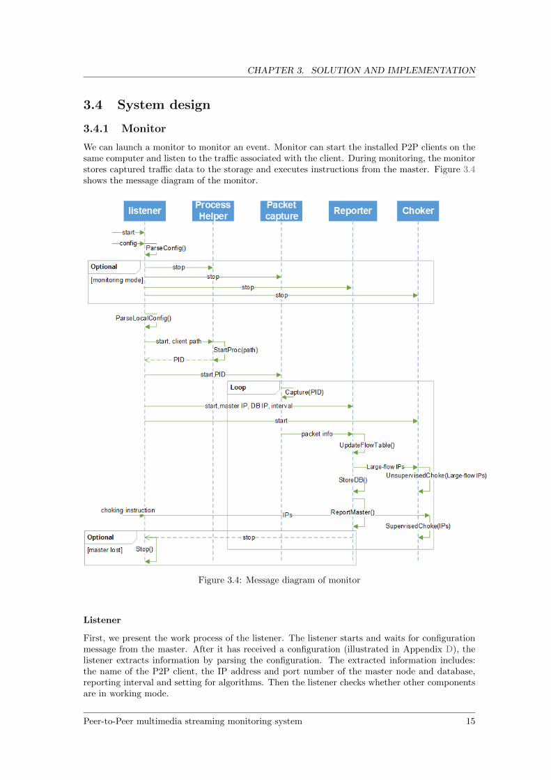
We can launch a monitor to monitor an event. Monitor can start the installed P2P clients on thesame computer and listen to the traffic associated with the client. During monitoring, the monitorstores captured traffic data to the storage and executes instructions from the master. Figure 3.4shows the message diagram of the monitor.
Figure 3.4: Message diagram of monitor
Listener
First, we present the work process of the listener. The listener starts and waits for configurationmessage from the master. After it has received a configuration (illustrated in Appendix D), thelistener extracts information by parsing the configuration. The extracted information includes:the name of the P2P client, the IP address and port number of the master node and database,reporting interval and setting for algorithms. Then the listener checks whether other componentsare in working mode.
Peer-to-Peer multimedia streaming monitoring system 15
CHAPTER 3. SOLUTION AND IMPLEMENTATION
If the components are in working mode, the listener sends a stop message to each of them.Then the process helper shuts down the running P2P client, the packet capture clears the bufferedpackets and stops capturing, the reporter closes current connections to the master and database,and the choker empt the blocking IP list.
If they are not in working mode, the listener parses a local configuration (illustrated in Ap-pendix D) to find the path of the P2P client. After locating the client, the listener sends a startcommand, with the client path, to the process helper. The process helper starts the client andreturns the Process Identifier (PID) back to the listener. To capture the traffic of the client,the listener sends start message to the packet capture. The packet capture intercepts the trafficfrom/to the client and extracts packet information. The reporter receives a start message thatcontains the IP addresses and port numbers of the master node and database, and connects tothem. Periodically, the reporter stores captured information (from the packet capture) to thedatabase and sends observed IP addresses to the master. The listener also sends a start messageto the choker, which creates an empty IP list. In the next steps, the IP list contains IP addressesthat should be blocked bidirectionally.
The listener also accepts choking instruction from master. The choking instruction is a list ofIP addresses that should be blocked by the monitor.
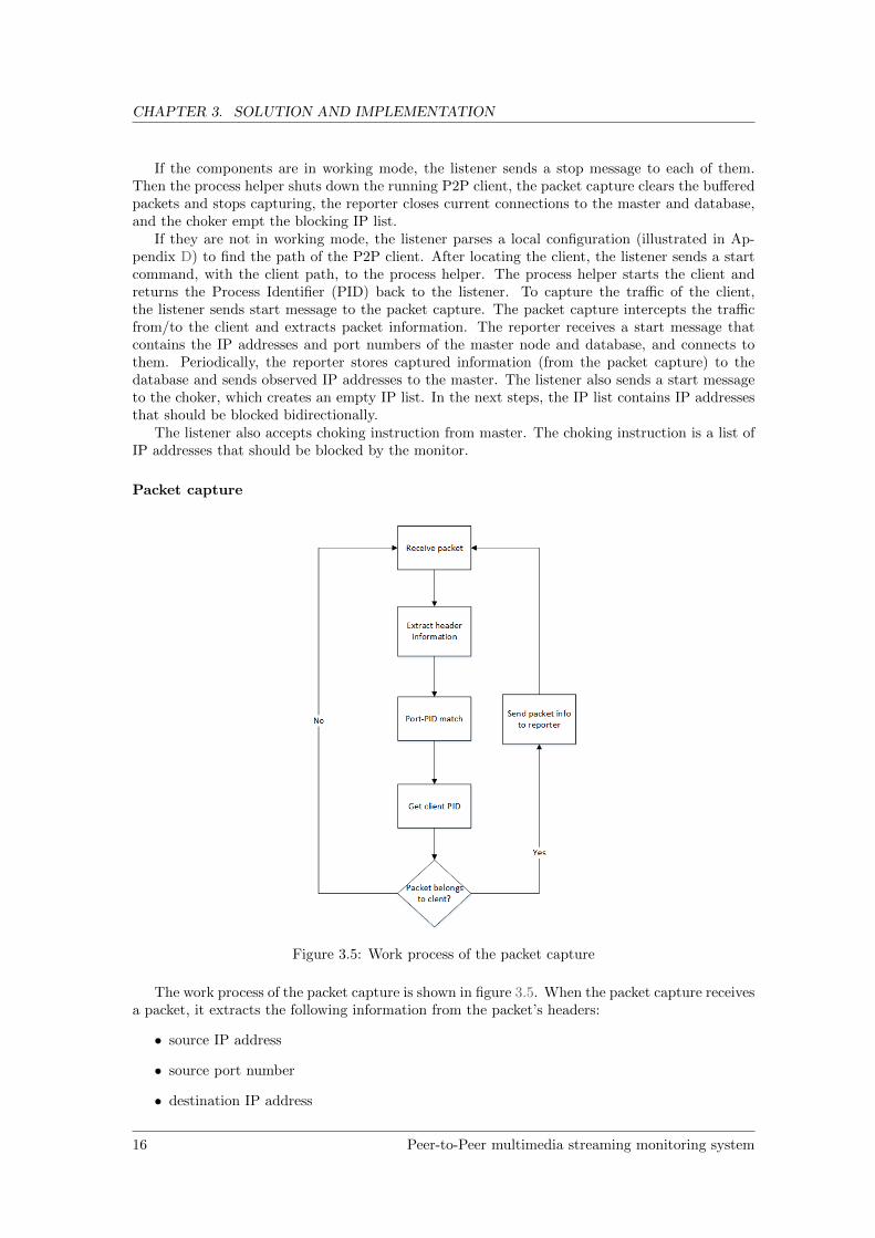
Packet capture
Figure 3.5: Work process of the packet capture
The work process of the packet capture is shown in figure 3.5. When the packet capture receivesa packet, it extracts the following information from the packet’s headers:
• source IP address
• source port number
• destination IP address
16 Peer-to-Peer multimedia streaming monitoring system
CHAPTER 3. SOLUTION AND IMPLEMENTATION
• destination port number
• protocol (TCP or UDP)
• size of packet (in bytes)
• captured time (in milliseconds)
The packet is captured through SharpPcap library, which utilizes Network Driver Interface Specifi-cation(NDIS). NDIS is an interface between the Network Interface Card (NIC) and other software.In OSI model, it is a part of layer 2. From NDIS, we can intercept the traffic from NIC to upperlayer’s software. Thus, through the SharpPcap library, we can get all the packets from the NIC.
Next, the packet capture gets a PID-port table through Windows IP-helper API. The PID-port table contains information of currently opening ports and ports’ corresponding PIDs. Thepacket capture compares the PID of the P2P client with the PIDs we get from the packet’s portnumbers (source and destination). If the the source port’s corresponding PID is equal to the PIDof the P2P client, we regard the packet as a packet going from the client. If the destination port’scorresponding PID is equal to the PID of the P2P client, we regard the packet as a packet goingto the client. Otherwise, the packet is ignored.
When the packet capture gets a packet belonging to the P2P client, it sends the extractedpacket information to the reporter.
Reporter
The reporter maintains a connection to the master node and a connection to the database. It alsomaintains a flow table data structure. The flow table contains the following fields:
• source IP address
• destination port number
• source IP address
• destination port number
• type of protocol (TCP or UDP)
• total number of packets
• total length of packets (in bytes)
• duration (the captured time of the last packet minus the captured time of the first packet)
• number of large packets ( > 1000 bytes)
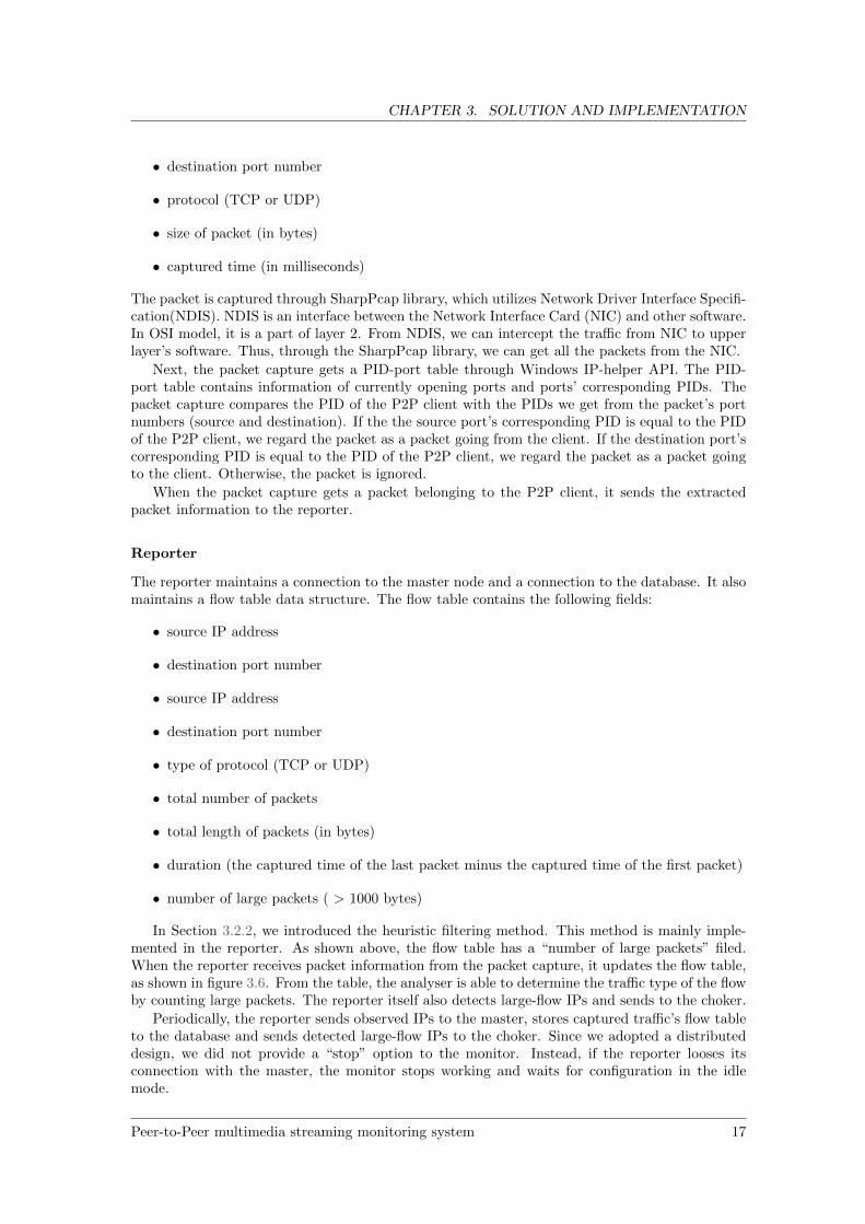
In Section 3.2.2, we introduced the heuristic filtering method. This method is mainly imple-mented in the reporter. As shown above, the flow table has a “number of large packets” filed.When the reporter receives packet information from the packet capture, it updates the flow table,as shown in figure 3.6. From the table, the analyser is able to determine the traffic type of the flowby counting large packets. The reporter itself also detects large-flow IPs and sends to the choker.
Periodically, the reporter sends observed IPs to the master, stores captured traffic’s flow tableto the database and sends detected large-flow IPs to the choker. Since we adopted a distributeddesign, we did not provide a “stop” option to the monitor. Instead, if the reporter looses itsconnection with the master, the monitor stops working and waits for configuration in the idlemode.
Peer-to-Peer multimedia streaming monitoring system 17
CHAPTER 3. SOLUTION AND IMPLEMENTATION
Figure 3.6: Flow updating process of reporter
Choker
We propose a choking mechanism to improve the measurement ability of the monitor. We assumethat breaking the P2P client’s connections with its neighbours can force the client to contact newpeers. The assumption is made based on P2P networks’ collaboration essence, which states thateach peer shares its resource and tries to get resources from other peers [20].
The choking mechanism is implemented using Windows Firewall API. When the choker starts,it creates a firewall rule through the Windows Firewall API. Windows Firewall is an software thatcan block packets that match some give conditions. The firewall rule is initialized as a bidirectionalblocking rule with an empty domain. If we add one IP to the rule’s domain, the bidirectional trafficof this IP is blocked by the firewall. When the choker receives IP addresses from the listener, itpopulates the firewall rule with the received IPs.
The choking mechanism needs to be conducted by an algorithm. In the monitor, we use anunsupervised choking algorithm to improve the monitor’s measurement ability. The principle ofthis algorithm is that we assume that peers which have large amount of traffic with the P2Pclient are neighbour peers, and we choke them. The reason we call this algorithm unsupervisedis that the monitor decides what IPs to choke by itself, without external instructions. As shownin figure 3.4, periodically the reporter sends detected large-flow IPs to the choker, and the chokerperforms unsupervised choking.
We have a setting for choking start-up-delay. We only enable choking on the client after theclient has been running for a period of time because the client has high peer discovery ability atits initial phase (shown in our experiments in Chapter 4), and we do not want to interfere with it.
3.4.2 Master
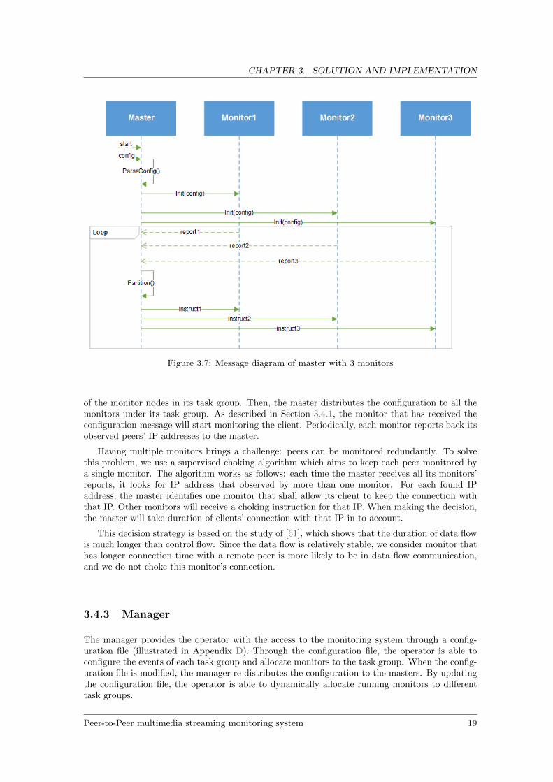
The message diagram of the master is shown in figure 3.7. Master starts and listens to configurationfrom the manager. After receiving a configuration, the master parses it and finds the IP addresses
18 Peer-to-Peer multimedia streaming monitoring system
CHAPTER 3. SOLUTION AND IMPLEMENTATION
Figure 3.7: Message diagram of master with 3 monitors
of the monitor nodes in its task group. Then, the master distributes the configuration to all themonitors under its task group. As described in Section 3.4.1, the monitor that has received theconfiguration message will start monitoring the client. Periodically, each monitor reports back itsobserved peers’ IP addresses to the master.
Having multiple monitors brings a challenge: peers can be monitored redundantly. To solvethis problem, we use a supervised choking algorithm which aims to keep each peer monitored bya single monitor. The algorithm works as follows: each time the master receives all its monitors’reports, it looks for IP address that observed by more than one monitor. For each found IPaddress, the master identifies one monitor that shall allow its client to keep the connection withthat IP. Other monitors will receive a choking instruction for that IP. When making the decision,the master will take duration of clients’ connection with that IP in to account.
This decision strategy is based on the study of [61], which shows that the duration of data flowis much longer than control flow. Since the data flow is relatively stable, we consider monitor thathas longer connection time with a remote peer is more likely to be in data flow communication,and we do not choke this monitor’s connection.
3.4.3 Manager
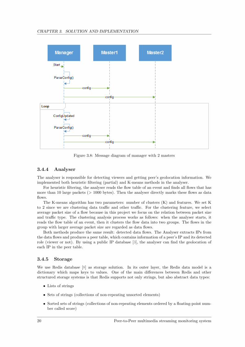
The manager provides the operator with the access to the monitoring system through a config-uration file (illustrated in Appendix D). Through the configuration file, the operator is able toconfigure the events of each task group and allocate monitors to the task group. When the config-uration file is modified, the manager re-distributes the configuration to the masters. By updatingthe configuration file, the operator is able to dynamically allocate running monitors to differenttask groups.
Peer-to-Peer multimedia streaming monitoring system 19
CHAPTER 3. SOLUTION AND IMPLEMENTATION
Figure 3.8: Message diagram of manager with 2 masters
3.4.4 Analyser
The analyser is responsible for detecting viewers and getting peer’s geolocation information. Weimplemented both heuristic filtering (partial) and K-means methods in the analyser.
For heuristic filtering, the analyser reads the flow table of an event and finds all flows that hasmore than 10 large packets (> 1000 bytes). Then the analyser directly marks these flows as dataflows.
The K-means algorithm has two parameters: number of clusters (K) and features. We set Kto 2 since we are clustering data traffic and other traffic. For the clustering feature, we selectaverage packet size of a flow because in this project we focus on the relation between packet sizeand traffic type. The clustering analysis process works as follows: when the analyser starts, itreads the flow table of an event, then it clusters the flow data into two groups. The flows in thegroup with larger average packet size are regarded as data flows.
Both methods produce the same result: detected data flows. The Analyser extracts IPs fromthe data flows and produces a peer table, which contains information of a peer’s IP and its detectedrole (viewer or not). By using a public IP database [3], the analyser can find the geolocation ofeach IP in the peer table.
3.4.5 Storage
We use Redis database [8] as storage solution. In its outer layer, the Redis data model is adictionary which maps keys to values. One of the main differences between Redis and otherstructured storage systems is that Redis supports not only strings, but also abstract data types:
• Lists of strings
• Sets of strings (collections of non-repeating unsorted elements)
• Sorted sets of strings (collections of non-repeating elements ordered by a floating-point num-ber called score)
20 Peer-to-Peer multimedia streaming monitoring system
CHAPTER 3. SOLUTION AND IMPLEMENTATION
• Hashes where keys and values are strings
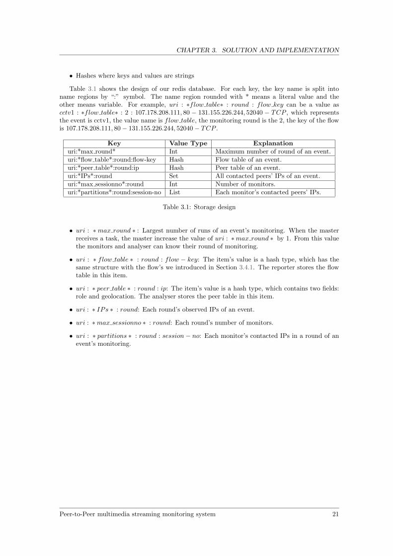
Table 3.1 shows the design of our redis database. For each key, the key name is split intoname regions by “:” symbol. The name region rounded with * means a literal value and theother means variable. For example, uri : ∗flow table∗ : round : flow key can be a value ascctv1 : ∗flow table∗ : 2 : 107.178.208.111, 80 − 131.155.226.244, 52040 − TCP , which representsthe event is cctv1, the value name is flow table, the monitoring round is the 2, the key of the flowis 107.178.208.111, 80 − 131.155.226.244, 52040 − TCP .
Key Value Type Explanationuri:*max round* Int Maximum number of round of an event.uri:*flow table*:round:flow-key Hash Flow table of an event.uri:*peer table*:round:ip Hash Peer table of an event.uri:*IPs*:round Set All contacted peers’ IPs of an event.uri:*max sessionno*:round Int Number of monitors.uri:*partitions*:round:session-no List Each monitor’s contacted peers’ IPs.
Table 3.1: Storage design
• uri : ∗max round ∗ : Largest number of runs of an event’s monitoring. When the masterreceives a task, the master increase the value of uri : ∗max round ∗ by 1. From this valuethe monitors and analyser can know their round of monitoring.
• uri : ∗ flow table ∗ : round : flow − key: The item’s value is a hash type, which has thesame structure with the flow’s we introduced in Section 3.4.1. The reporter stores the flowtable in this item.
• uri : ∗ peer table ∗ : round : ip: The item’s value is a hash type, which contains two fields:role and geolocation. The analyser stores the peer table in this item.
• uri : ∗ IPs ∗ : round: Each round’s observed IPs of an event.
• uri : ∗max sessionno ∗ : round: Each round’s number of monitors.
• uri : ∗ partitions ∗ : round : session− no: Each monitor’s contacted IPs in a round of anevent’s monitoring.
Peer-to-Peer multimedia streaming monitoring system 21
Chapter 4
Evaluation
In this section we present five sets of experiments on our monitoring system, first four evaluatethe measurement performance of our system, the last one evaluates the analysis performance.
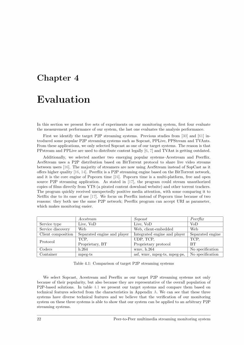
First we identify the target P2P streaming systems. Previous studies from [30] and [61] in-troduced some popular P2P streaming systems such as Sopcast, PPLive, PPStream and TVAnts.From these applications, we only selected Sopcast as one of our target systems. The reason is thatPPstream and PPLive are used to distribute content legally [6, 7] and TVAnt is getting outdated.
Additionally, we selected another two emerging popular systems–Acestream and Peerflix.AceStream uses a P2P distribution based on BitTorrent protocol to share live video streamsbetween users [16]. The majority of streamers are now using AceStream instead of SopCast as itoffers higher quality [16, 14]. Peerflix is a P2P streaming engine based on the BitTorrent network,and it is the core engine of Popcorn time [24]. Popcorn time is a multi-platform, free and opensource P2P streaming application. As stated in [17], the program could stream unauthorizedcopies of films directly from YTS (a pirated content download website) and other torrent trackers.The program quickly received unexpectedly positive media attention, with some comparing it toNetflix due to its ease of use [17]. We focus on Peerflix instead of Popcorn time because of tworeasons: they both use the same P2P network; Peerflix program can accept URI as parameter,which makes monitoring easier.
Acestream Sopcast PeerflixService type Live, VoD Live, VoD VoDService discovery Web Web, client-embedded WebClient composition Separated engine and player Integrated engine and player Separated engine
ProtocolTCP,Proprietary, BT
UDP, TCP,Proprietary protocol
TCP,BT
Codecs h.264 wmv, h.264 No specificationContainer mpeg-ts asf, wmv, mpeg-ts, mpeg-ps, No specification
Table 4.1: Comparison of target P2P streaming systems
We select Sopcast, Acestream and Peerflix as our target P2P streaming systems not onlybecause of their popularity, but also because they are representative of the overall population ofP2P-based solutions. In table 4.1 we present our target systems and compare them based ontechnical features selected from the characteristics in Appendix A. We can see that these threesystems have diverse technical features and we believe that the verification of our monitoringsystem on these three systems is able to show that our system can be applied to an arbitrary P2Pstreaming systems.
22 Peer-to-Peer multimedia streaming monitoring system
CHAPTER 4. EVALUATION
4.1 Measurement
4.1.1 Distributed experiment
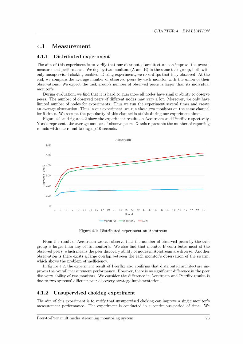
The aim of this experiment is to verify that our distributed architecture can improve the overallmeasurement performance. We deploy two monitors (A and B) in the same task group, both withonly unsupervised choking enabled. During experiment, we record Ips that they observed. At theend, we compare the average number of observed peers by each monitor with the union of theirobservations. We expect the task group’s number of observed peers is larger than its individualmonitor’s.
During evaluation, we find that it is hard to guarantee all nodes have similar ability to observepeers. The number of observed peers of different nodes may vary a lot. Moreover, we only havelimited number of nodes for experiments. Thus we run the experiment several times and createan average observation. Thus in our experiment, we run these two monitors on the same channelfor 5 times. We assume the popularity of this channel is stable during our experiment time.
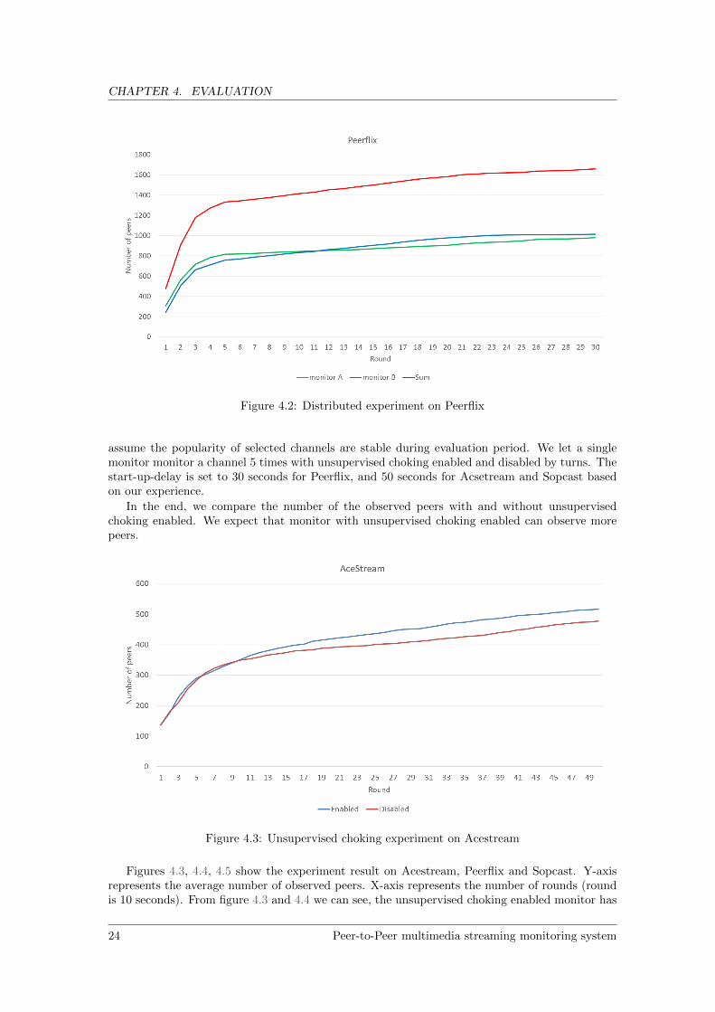
Figure 4.1 and figure 4.2 show the experiment results on Acestream and Peerflix respectively.Y-axis represents the average number of observe peers. X-axis represents the number of reportingrounds with one round taking up 10 seconds.
Figure 4.1: Distributed experiment on Acestream
From the result of Acestream we can observe that the number of observed peers by the taskgroup is larger than any of its monitor’s. We also find that monitor B contributes most of theobserved peers, which means the peer discovery ability of nodes in Acestream are diverse. Anotherobservation is there exists a large overlap between the each monitor’s observation of the swarm,which shows the problem of inefficiency.
In figure 4.2, the experiment result of Peerflix also confirms that distributed architecture im-proves the overall measurement performance. However, there is no significant difference in the peerdiscovery ability of two monitors. We consider the difference in Acestream and Peerflix results isdue to two systems’ different peer discovery strategy implementation.
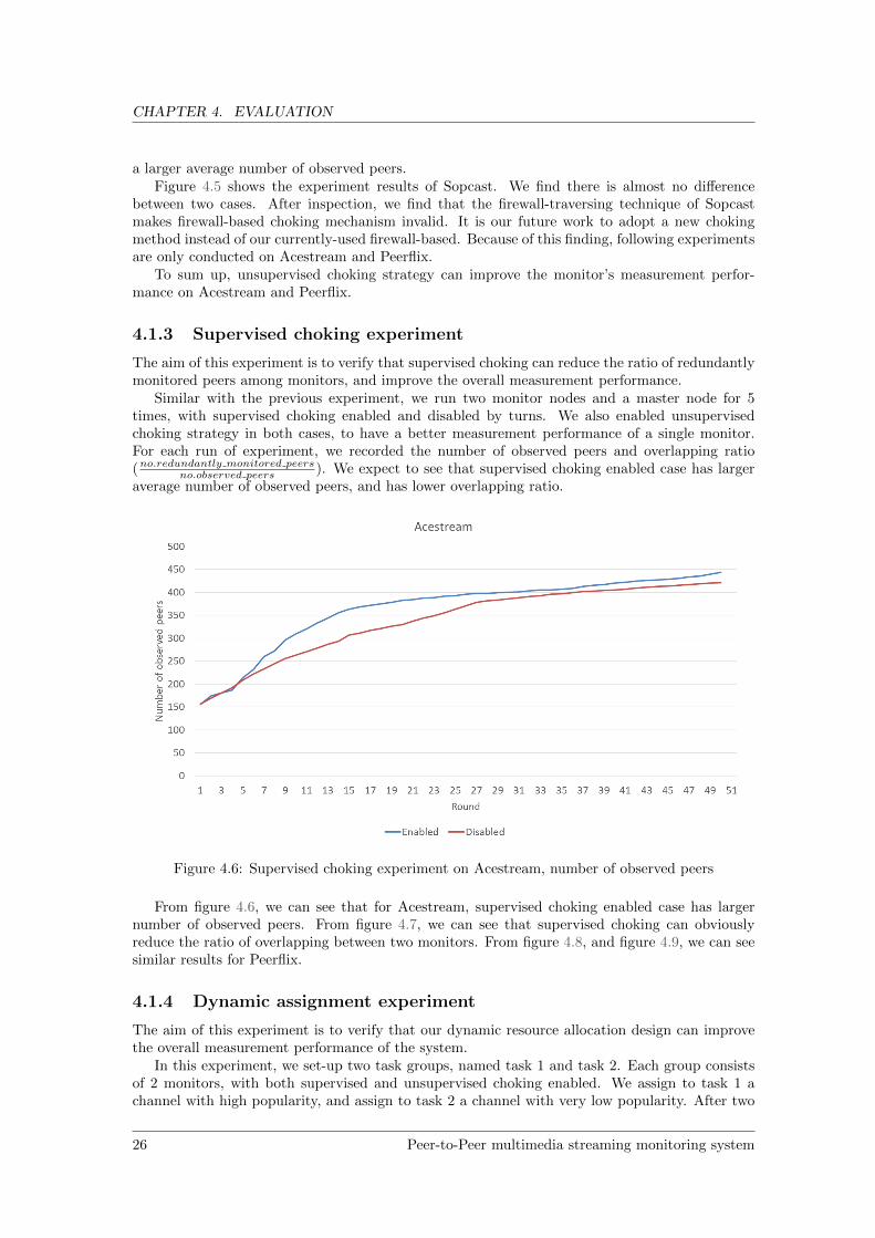
4.1.2 Unsupervised choking experiment
The aim of this experiment is to verify that unsupervised choking can improve a single monitor’smeasurement performance. The experiment is conducted in a continuous period of time. We
Peer-to-Peer multimedia streaming monitoring system 23
CHAPTER 4. EVALUATION
Figure 4.2: Distributed experiment on Peerflix
assume the popularity of selected channels are stable during evaluation period. We let a singlemonitor monitor a channel 5 times with unsupervised choking enabled and disabled by turns. Thestart-up-delay is set to 30 seconds for Peerflix, and 50 seconds for Acsetream and Sopcast basedon our experience.
In the end, we compare the number of the observed peers with and without unsupervisedchoking enabled. We expect that monitor with unsupervised choking enabled can observe morepeers.
Figure 4.3: Unsupervised choking experiment on Acestream
Figures 4.3, 4.4, 4.5 show the experiment result on Acestream, Peerflix and Sopcast. Y-axisrepresents the average number of observed peers. X-axis represents the number of rounds (roundis 10 seconds). From figure 4.3 and 4.4 we can see, the unsupervised choking enabled monitor has
24 Peer-to-Peer multimedia streaming monitoring system
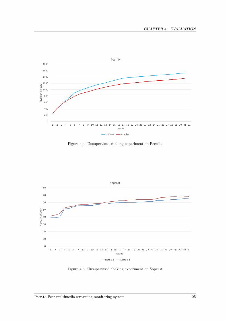
CHAPTER 4. EVALUATION
Figure 4.4: Unsupervised choking experiment on Peerflix
Figure 4.5: Unsupervised choking experiment on Sopcast
Peer-to-Peer multimedia streaming monitoring system 25
CHAPTER 4. EVALUATION
a larger average number of observed peers.Figure 4.5 shows the experiment results of Sopcast. We find there is almost no difference
between two cases. After inspection, we find that the firewall-traversing technique of Sopcastmakes firewall-based choking mechanism invalid. It is our future work to adopt a new chokingmethod instead of our currently-used firewall-based. Because of this finding, following experimentsare only conducted on Acestream and Peerflix.
To sum up, unsupervised choking strategy can improve the monitor’s measurement perfor-mance on Acestream and Peerflix.
4.1.3 Supervised choking experiment
The aim of this experiment is to verify that supervised choking can reduce the ratio of redundantlymonitored peers among monitors, and improve the overall measurement performance.
Similar with the previous experiment, we run two monitor nodes and a master node for 5times, with supervised choking enabled and disabled by turns. We also enabled unsupervisedchoking strategy in both cases, to have a better measurement performance of a single monitor.For each run of experiment, we recorded the number of observed peers and overlapping ratio(no.redundantly monitored peers
no.observed peers ). We expect to see that supervised choking enabled case has largeraverage number of observed peers, and has lower overlapping ratio.
Figure 4.6: Supervised choking experiment on Acestream, number of observed peers
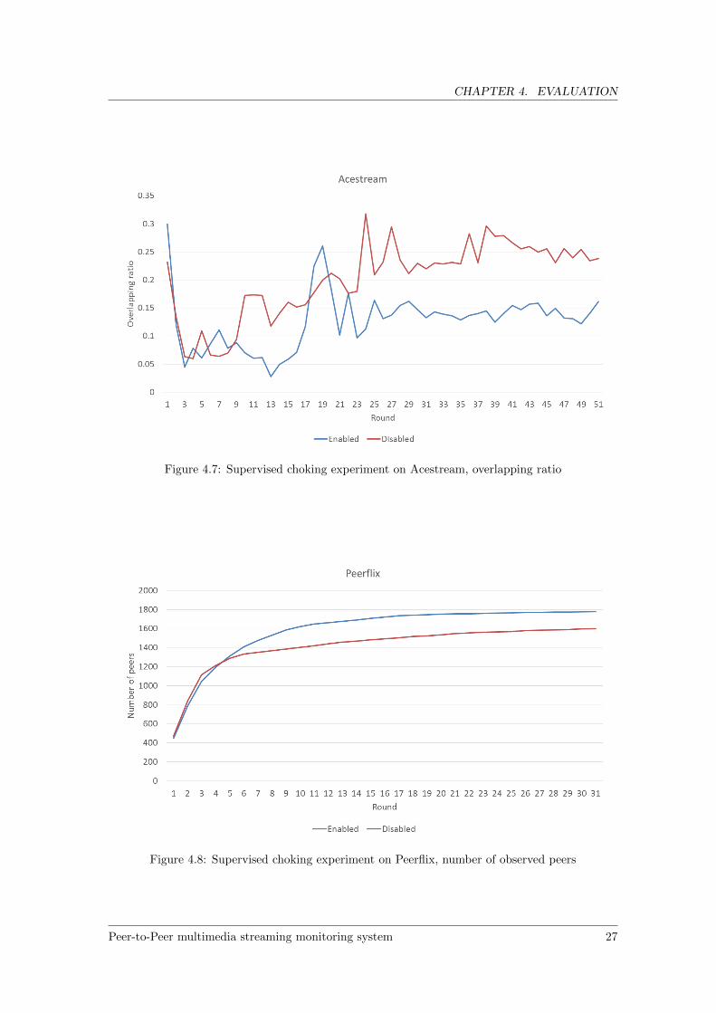
From figure 4.6, we can see that for Acestream, supervised choking enabled case has largernumber of observed peers. From figure 4.7, we can see that supervised choking can obviouslyreduce the ratio of overlapping between two monitors. From figure 4.8, and figure 4.9, we can seesimilar results for Peerflix.
4.1.4 Dynamic assignment experiment
The aim of this experiment is to verify that our dynamic resource allocation design can improvethe overall measurement performance of the system.
In this experiment, we set-up two task groups, named task 1 and task 2. Each group consistsof 2 monitors, with both supervised and unsupervised choking enabled. We assign to task 1 achannel with high popularity, and assign to task 2 a channel with very low popularity. After two
26 Peer-to-Peer multimedia streaming monitoring system
CHAPTER 4. EVALUATION
Figure 4.7: Supervised choking experiment on Acestream, overlapping ratio
Figure 4.8: Supervised choking experiment on Peerflix, number of observed peers
Peer-to-Peer multimedia streaming monitoring system 27

CHAPTER 4. EVALUATION
Figure 4.9: Supervised choking experiment on Peerflix, overlapping ratio
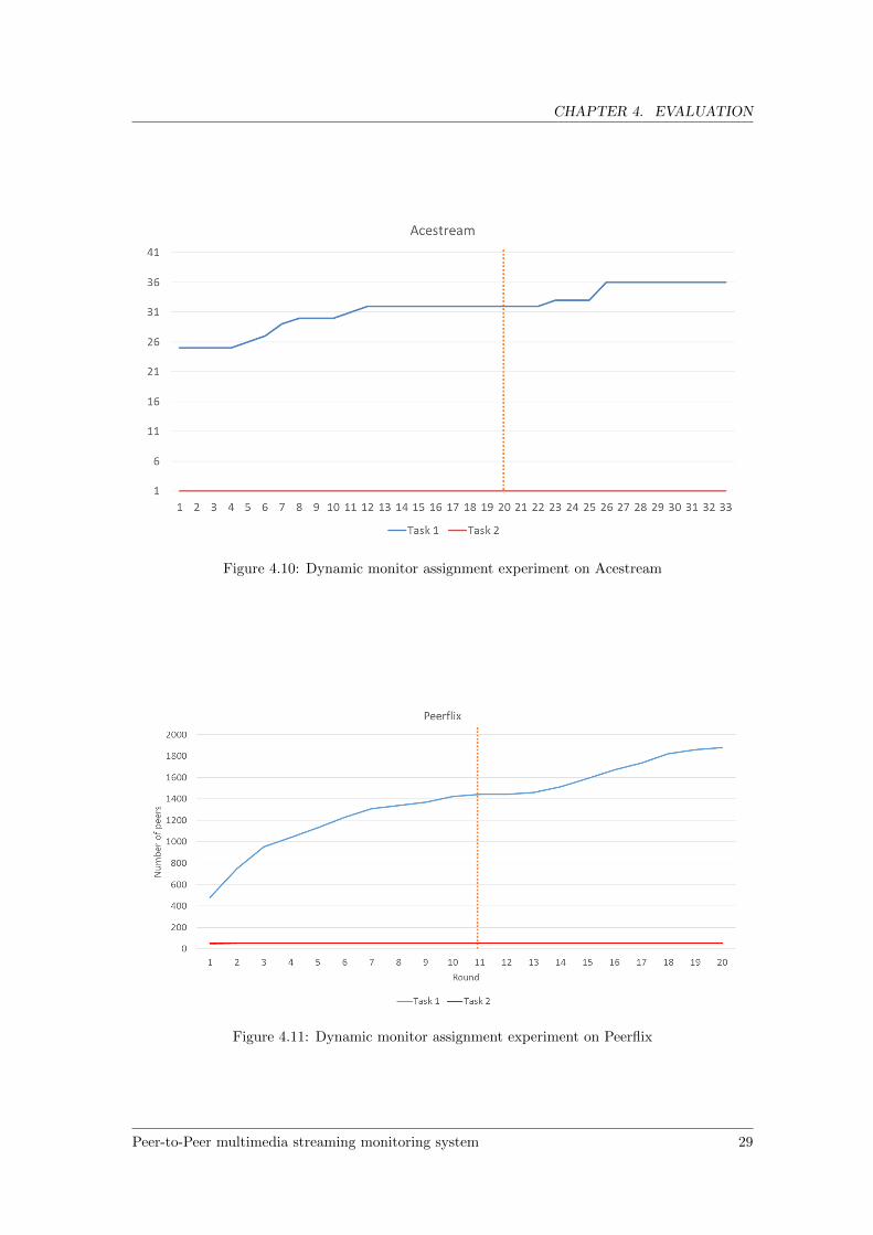
tasks have been running for a while (we choose 20 rounds on Acestream, 11 rounds on Peerflix),we re-assign one node from task 2 to task 1. We use this experiment to simulate the scenariothat during monitoring we re-allocate under-utilized monitors to another task in order to balancethe load of the whole system. We expect that overall observed number of peers can increase afterreallocation.
There is a difference in Acestream experiment that we cannot use the number of observedpeers as a metric of channel popularity. This is because we find Acestream client contacts a largenumber of non-viewers regardless of the popularity of channels. Instead, we use another metric:number of viewers detected by the heuristic filtering method.
From figures 4.10 4.11, we can see that around round 11 for Peerflix and round 21 for Acestream(which corresponds to re-allocation time), the number of observed peers increases.
28 Peer-to-Peer multimedia streaming monitoring system
CHAPTER 4. EVALUATION
Figure 4.10: Dynamic monitor assignment experiment on Acestream
Figure 4.11: Dynamic monitor assignment experiment on Peerflix
Peer-to-Peer multimedia streaming monitoring system 29

CHAPTER 4. EVALUATION
4.2 Viewer detection
We evaluated the performance of our two traffic classification methods on Sopcast which has beenwidely studied [19, 61]. In this experiment, we compare the ratio of detected viewers among allobserved peers in an monitored event by using two proposed methods, there is no ground truth inencrypted P2P communication [51].
In [19], the authors show that in Sopcast, the ratio of contacted viewers among contacted peersis around 37.29%. Similarly, in [33], the authors show this ratio is around 35%. We selected 4Sopcast events to monitor. For each event, we monitored 3 times, each time for 20 minutes. Weexpect that our both methods provide a ratio that is comparable the other two studies’ results.
The comparison result is shown in the table below.
Classification method Ratio of viewers among all observed peersCiullo et al 37.29%Horvath et al about 35%Heuristic filtering 32.72%K-means 24.68%
Table 4.2: Viewer detection experiment
We find that the result of heuristic filtering is close with the previous studies’. We assumethe reason for such similarity is that those two studies also use the size of packet as a heuristic.K-means detects less viewers, which means it performance is not as good as heuristic filtering onSopcast. In future we need further study on K-means to improve its performance. We considerthe input data and selection on features as two important factors for the future study.
30 Peer-to-Peer multimedia streaming monitoring system

Chapter 5
Conclusions
In this project, we proposed a solution for measurement and analysis of an arbitrary P2P streamingsystem. In order to achieve this goal, we studied the architectures of P2P streaming systems,traffic measurement methodologies and traffic analysis methodologies. In the end, we presented amonitoring system based on passive measurement and flow-level traffic statistic analysis.
The focus of our project is placed on the measurement part. In order to improve the mea-surement performance, we solved several challenges. The first challenge is the scalability of ourmeasurement system: the monitor’s measurement ability cannot scale with the size of the P2Pnetwork. To deal with this challenge, we adopted a distributed architecture, in which multiplemonitors are coordinated by a central master node. The second challenge we solved is the visi-bility limitation of a single monitor. To address it, we proposed an unsupervised choking methodthat can force the monitor to observe more peers by breaking the client’s connections with cur-rent neighbour peers. The third challenge we solved is the redundant observation of peers amongmultiple monitors. To solve this challenge, we proposed a supervised choking method. For eachredundantly monitored peer, we keep one monitor’s connection with that peer and choke the rest.The effectiveness of these approaches is verified in our evaluation experiments. In addition, oursystem architecture supports dynamic resource allocation, which can help us to balance the loadamong multiple monitoring tasks.
On the analysis side, we proposed a viewer detection method by traffic classification. We useda heuristic filtering approach to detect data flows and identify viewers. Additionally, we studiedclustering algorithm to distinguish data traffic and control traffic. We found heuristic filtering hasa good performance and clustering does not. However, the heuristic filtering method’s accuracylargely depends on the setting of packet threshold, which may differ for different systems, whereas,clustering is universal for different systems. One limitation in our viewer analysis is that we onlyconsidered the role of viewer but not consider the role of uploader and downloader.
Currently, in our system the load balancing is a manual process as introduced above. In future,an automated load balancing module can be useful. For example, the module can automatically as-sign more monitors to the the task group with lower overlapping ratio (no.redundantly monitored peers
no.observed peers ),since the lower ratio implies that a new monitor may contribute its resources to the task group.
One of the limitations of our monitor is that our firewall-based choking mechanism does notwork with Sopcast, which has a firewall traverse feature. In the future we need to replace ourfirewall-based choking module with a new one. The new choking module should have the abilityto catch and drop packets that matches a specified condition. Such module shall be based on theNDIS implementation (e.g. Netlimiter [4]).
Another limitation of our monitor is that each monitor can only run one monitoring task ata time, which causes a waste of computation resource. To break the limitation, we need to finda solution for two cases in figure 5.1. The first case is that each P2P player is connected with acorresponding engine. In this case, we only need to filter the packet to each engine, which is similarwith our current implementation. The second case is more complex since only one engine receivespackets from multiple players simultaneously, and we cannot associate packets with a particular
Peer-to-Peer multimedia streaming monitoring system 31
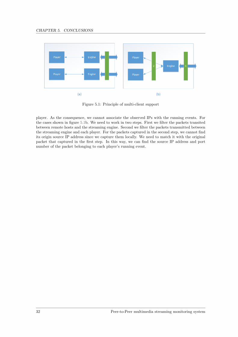
CHAPTER 5. CONCLUSIONS
Figure 5.1: Principle of multi-client support
player. As the consequence, we cannot associate the observed IPs with the running events. Forthe cases shown in figure 5.1b. We need to work in two steps. First we filter the packets transitedbetween remote hosts and the streaming engine. Second we filter the packets transmitted betweenthe streaming engine and each player. For the packets captured in the second step, we cannot findits origin source IP address since we capture them locally. We need to match it with the originalpacket that captured in the first step. In this way, we can find the source IP address and portnumber of the packet belonging to each player’s running event.
32 Peer-to-Peer multimedia streaming monitoring system
Bibliography
[1] Geolocation software. http://en.wikipedia.org/wiki/Geolocation_software. 3
[2] H.264 wiki page. http://en.wikipedia.org/wiki/H.264/MPEG-4_AVC. 39, 40
[3] Maxmind GeoIP2 City. https://www.maxmind.com/en/city. 20
[4] Netlimiter homepage. http://www.netlimiter.com/. 31
[5] Olfeo protocol list. http://www.olfeo.com/sites/olfeo/files/english_site/pdf/
protocol-list-olfeo.pdf. 43
[6] PPLive official website. http://www.pplive.com. 6, 22
[7] PPStream official website. http://www.pps.tvss. 6, 22
[8] Redis database. http://redis.io/. 20
[9] RSVP, Network Working Group. http://ftp.isi.edu/in-notes/rfc2205.txt. 43
[10] RTP, Network Working Group. https://www.ietf.org/rfc/rfc3550.txt. 43
[11] RTSP, Network Working Group. http://www.ietf.org/rfc/rfc2326.txt. 43
[12] Sopcast homepage. http://www.sopcast.com/. 46
[13] VC-1 wiki page. http://en.wikipedia.org/wiki/VC-1. 40
[14] Wizwig. http://www.wiziwig.tv/softwareitem.php?softwareid=28&part=software. 22
[15] WMV wiki page. http://en.wikipedia.org/wiki/Windows_Media_Video. 40
[16] Acestream guide. http://acestreamguide.com/, 2014. 22
[17] Popcorn time wiki page. http://en.wikipedia.org/wiki/Popcorn_Time, 2014. 22
[18] Shahzad Ali, Anket Mathur, and Hui Zhang. Measurement of commercial peer-to-peer livevideo streaming. Citeseer. 6, 8
[19] Delia Ciullo, Maria Antonieta Garcia, Akos Horvath, Emilio Leonardi, Marco Mellia, DarioRossi, Miklos Telek, and Paolo Veglia. Network awareness of p2p live streaming applications:a measurement study. Multimedia, IEEE Transactions on, 12(1):54–63, 2010. 11, 30
[20] Delia Ciullo, Marco Mellia, Michela Meo, and Emilio Leonardi. Understanding p2p-tv sys-tems through real measurements. In Global Telecommunications Conference, 2008. IEEEGLOBECOM 2008. IEEE, pages 1–6. IEEE, 2008. 8, 18
[21] Gregory J Conklin, Gary S Greenbaum, Karl Olav Lillevold, Alan F Lippman, and Yuriy AReznik. Video coding for streaming media delivery on the internet. Circuits and Systems forVideo Technology, IEEE Transactions on, 11(3):269–281, 2001. 40, 41
Peer-to-Peer multimedia streaming monitoring system 33

BIBLIOGRAPHY
[22] Hrishikesh Deshpande, Mayank Bawa, and Hector Garcia-Molina. Streaming live media overa peer-to-peer network. Technical Report, 2001. 8
[23] Jeffrey Erman, Martin Arlitt, and Anirban Mahanti. Traffic classification using clusteringalgorithms. In Proceedings of the 2006 SIGCOMM workshop on Mining network data, pages281–286. ACM, 2006. 2, 3, 8, 11, 12, 13
[24] Sebastian etc. Popcorn time github page. https://github.com/popcorn-time/
popcorn-app/, 2014. 22
[25] Kevin R Fall and W Richard Stevens. TCP/IP illustrated, volume 1: The protocols. addison-Wesley, 2011. 42
[26] Benedetto Fallica. Measurement study of the P2PTV application SopCast. Master’s thesis,Delft University of Technology, 2007. 8
[27] A. Ganjam and Hui Zhang. Internet multicast video delivery. Proceedings of the IEEE,93(1):159–170, Jan 2005. 6
[28] Jagannath Ghoshal, Lisong Xu, Byrav Ramamurthy, and Miao Wang. Network architecturesfor live peer-to-peer media streaming. 2007. 6, 7
[29] Se-Hee Han, Myung-Sup Kim, Hong-Taek Ju, and James Won-Ki Hong. The architecture ofng-mon: A passive network monitoring system for high-speed ip networks1. In ManagementTechnologies for E-Commerce and E-Business Applications, pages 16–27. Springer, 2002. 8,11
[30] Xiaojun Hei, Chao Liang, Jian Liang, Yong Liu, and Keith W Ross. A measurement studyof a large-scale p2p iptv system. Multimedia, IEEE Transactions on, 9(8):1672–1687, 2007.3, 8, 12, 22
[31] Xiaojun Hei, Yong Liu, and Keith W Ross. Iptv over p2p streaming networks: the mesh-pullapproach. Communications Magazine, IEEE, 46(2):86–92, 2008. 6, 7, 44, 47, 48, 50
[32] Takayuki Hisada, Shusuke Yamazaki, Yusuke Hirota, Hideki Tode, and Koso Murakami. P2plive streaming system suitable for private contents distribution. In Consumer Communicationsand Networking Conference (CCNC), 2010 7th IEEE, pages 1–5. IEEE, 2010. 6
[33] Akos Horvath, Miklos Telek, Dario Rossi, Paolo Veglia, Delia Ciullo, Maria Antonieta Garcia,Emilio Leonardi, and Marco Mellia. Dissecting pplive, sopcast, tvants. submitted to ACMConext, 2008. 30
[34] Piotr Indyk, Giridharan Iyengar, and Narayanan Shivakumar. Finding pirated video se-quences on the internet. Technical report, Technical report, Computer science department,Stanford university, 1999. 1
[35] Thomas Karagiannis, Andre Broido, Michalis Faloutsos, et al. Transport layer identification ofp2p traffic. In Proceedings of the 4th ACM SIGCOMM conference on Internet measurement,pages 121–134. ACM, 2004. 2
[36] Michael Karl, Tatiana Polishchuk, Thorsten Herfet, and Andrei Gurtov. Mediating multime-dia traffic with strict delivery constraints. 2013 IEEE International Symposium on Multime-dia, 0:241–248, 2012. 1
[37] Mandar Kelaskar, Vincent Matossian, Preeti Mehra, Dennis Paul, and Manish Parashar. Astudy of discovery mechanisms for peer-to-peer applications. In Cluster Computing and theGrid, 2002. 2nd IEEE/ACM International Symposium on, pages 444–444. IEEE, 2002. 7
34 Peer-to-Peer multimedia streaming monitoring system
BIBLIOGRAPHY
[38] Myung-Sup Kim, Hun-Jeong Kong, Seong-Cheol Hong, Seung-Hwa Chung, and James WHong. A flow-based method for abnormal network traffic detection. In Network operations andmanagement symposium, 2004. NOMS 2004. IEEE/IFIP, volume 1, pages 599–612. IEEE,2004. 11
[39] Franc Kozamernik. Media streaming over the internet–an overview of delivery technologies.EBU Technical Review, 10, 2002. 39, 40, 41, 42, 43
[40] Bo Li and Hao Yin. Peer-to-peer live video streaming on the internet: issues, existing ap-proaches, and challenges [peer-to-peer multimedia streaming]. Communications Magazine,IEEE, 45(6):94–99, 2007. 44, 45
[41] Chunlei Liu. Multimedia over ip: Rsvp, rtp, rtcp, rtsp. Handbook of Communication Tech-nologies: The Florida, 2000. 5, 39, 43
[42] Jiangchuan Liu, Sanjay G Rao, Bo Li, and Hui Zhang. Opportunities and challenges ofpeer-to-peer internet video broadcast. Proceedings of the IEEE, 96(1):11–24, 2008. 6, 48
[43] Yong Liu, Yang Guo, and Chao Liang. A survey on peer-to-peer video streaming systems.Peer-to-peer Networking and Applications, 1(1):18–28, 2008. 6, 7, 44, 50
[44] Xiaosong Lou and Kai Hwang. Collusive piracy prevention in p2p content delivery networks.Computers, IEEE Transactions on, 58(7):970–983, 2009. 2, 6
[45] Bruce B Lowekamp. Combining active and passive network measurements to build scal-able monitoring systems on the grid. ACM SIGMETRICS Performance Evaluation Review,30(4):19–26, 2003. 2
[46] Zhihui Lu, Ye Wang, and Yang Richard Yang. An analysis and comparison of cdn-p2p-hybridcontent delivery system and model. journal of communications, 7(3):232–245, 2012. 44, 45
[47] Kevin J Ma, Radim Bartos, and Swapnil Bhatia. A survey of schemes for internet-basedvideo delivery. Journal of Network and Computer Applications, 34(5):1572–1586, 2011. 5, 39,40, 41, 44
[48] Alok Madhukar and Carey Williamson. A longitudinal study of p2p traffic classification.In Modeling, Analysis, and Simulation of Computer and Telecommunication Systems, 2006.MASCOTS 2006. 14th IEEE International Symposium on, pages 179–188. IEEE, 2006. 3, 12
[49] Nazanin Magharei, Reza Rejaie, and Yang Guo. Mesh or multiple-tree: A comparative studyof live p2p streaming approaches. In INFOCOM 2007. 26th IEEE International Conferenceon Computer Communications. IEEE, pages 1424–1432. IEEE, 2007. 6, 7, 48
[50] Anthony McGregor, Mark Hall, Perry Lorier, and James Brunskill. Flow clustering usingmachine learning techniques. In Passive and Active Network Measurement, pages 205–214.Springer, 2004. 2, 3, 8, 12, 13
[51] Venkat Mohan, YR Janardhan Reddy, and K Kalpana. Active and passive network mea-surements: a survey. Int J Comput Sci Inf Technol, ISSN, pages 0975–9646, 2011. 2, 30,44
[52] Alexander Moshchuk, Tanya Bragin, Steven D Gribble, and Henry M Levy. A crawler-basedstudy of spyware in the web. In NDSS, 2006. 1, 2
[53] Panagiotis Papadimitriou. Multimedia streaming over the internet. 2004. 40, 41, 42, 45
[54] Byungchul Park, JW-K Hong, and Young J Won. Toward fine-grained traffic classification.Communications Magazine, IEEE, 49(7):104–111, 2011. 9
Peer-to-Peer multimedia streaming monitoring system 35
BIBLIOGRAPHY
[55] Andrea Passarella. A survey on content-centric technologies for the current internet: Cdnand p2p solutions. Computer Communications, 35(1):1–32, 2012. 44, 45
[56] D. Ratkaj. Distribution of multimedia services over the internet. In ELMAR, 2013 55thInternational Symposium, pages 1–5, Sept 2013. 2
[57] Reza Rejaie and Shad Stafford. A framework for architecting peer-to-peer receiver-drivenoverlays. In Proceedings of the 14th international workshop on Network and operating systemssupport for digital audio and video, pages 42–47. ACM, 2004. 7
[58] Janko Roettgers. Dont touch that dial: How youtube is bringing adaptive streaming to mobile,tvs. http://gigaom.com/2013/03/13/youtube-adaptive-streaming-mobile-tv/, March2013. 41
[59] Subhabrata Sen, Oliver Spatscheck, and Dongmei Wang. Accurate, scalable in-network iden-tification of p2p traffic using application signatures. In Proceedings of the 13th internationalconference on World Wide Web, pages 512–521. ACM, 2004. 3, 12
[60] P. Shah and J.-F. Paris. Peer-to-peer multimedia streaming using bittorrent. In Performance,Computing, and Communications Conference, 2007. IPCCC 2007. IEEE Internationa, pages340–347, April 2007. 7
[61] Thomas Silverston and Olivier Fourmaux. Measuring p2p iptv systems. In Proceedings ofNOSSDAV, volume 7, 2007. 2, 8, 12, 19, 22, 30
[62] Salvatore Spoto, Rossano Gaeta, Marco Grangetto, and Matteo Sereno. Analysis of pplivethrough active and passive measurements. In Parallel & Distributed Processing, 2009. IPDPS2009. IEEE International Symposium on, pages 1–7. IEEE, 2009. 2, 8
[63] Thomas Stockhammer. Dynamic adaptive streaming over http–: standards and design prin-ciples. In Proceedings of the second annual ACM conference on Multimedia systems, pages133–144. ACM, 2011. 41, 42, 43, 44
[64] Yun Tang, J Luo, Qian Zhang, Meng Zhang, and S Yang. Deploying p2p networks for large-scale live video-streaming service. IEEE Communications Magazine, 45(6):100, 2007. 2, 13
[65] Duc A Tran, Kien A Hua, and Tai Do. Zigzag: An efficient peer-to-peer scheme for me-dia streaming. In INFOCOM 2003. Twenty-Second Annual Joint Conference of the IEEEComputer and Communications. IEEE Societies, volume 2, pages 1283–1292. IEEE. 48, 50
[66] Andrew Turner. Geolocation by ip address. Linux Journal, Oct, 25, 2004. 3
[67] Dapeng Wu, Y.T. Hou, Wenwu Zhu, Ya-Qin Zhang, and J.M. Peha. Streaming video overthe internet: approaches and directions. Circuits and Systems for Video Technology, IEEETransactions on, 11(3):282–300, Mar 2001. 5, 40, 41, 42
[68] Gang Xiong et al. Research progress and prospects of network traffic classification. integrationtechnology, 1(1), 2012. 3, 11, 12, 44
[69] Dongyan Xu, Sunil Suresh Kulkarni, Catherine Rosenberg, and Heung-Keung Chai. Analysisof a cdn–p2p hybrid architecture for cost-effective streaming media distribution. MultimediaSystems, 11(4):383–399, 2006. 44, 45
[70] W-PK Yiu, Xing Jin, and S-HG Chan. Challenges and approaches in large-scale p2p mediastreaming. MultiMedia, IEEE, 14(2):50–59, 2007. 6, 7, 48, 50
[71] Alex Zambelli. Iis smooth streaming technical overview. Microsoft Corporation, 3, 2009. 40,41, 42
36 Peer-to-Peer multimedia streaming monitoring system
BIBLIOGRAPHY
[72] Sebastian Zander, Thuy Nguyen, and Grenville Armitage. Automated traffic classificationand application identification using machine learning. In Local Computer Networks, 2005.30th Anniversary. The IEEE Conference on, pages 250–257. IEEE, 2005. 8, 11
[73] Xinyan Zhang, Jiangchuan Liu, Bo Li, and Tak-Shing Peter Yum. Coolstreaming/donet: adata-driven overlay network for peer-to-peer live media streaming. In INFOCOM 2005. 24thAnnual Joint Conference of the IEEE Computer and Communications Societies. ProceedingsIEEE, volume 3, pages 2102–2111. IEEE, 2005. 6
Peer-to-Peer multimedia streaming monitoring system 37

Appendix A
Internet multimedia deliverytechnology characteristics
A.1 Service type
The multimedia services can be classified into two groups: live streaming and video-on-demand(VoD) [47,41].
• Live streaming: Live streaming refers to content delivered live over the Internet. The videodata to be served should be acquired in real-time. An application program called a broad-caster is needed. The broadcaster takes input from live sources, such as a video camera,microphone or an ordinary audio CD, compress these sources on the fly for transmission atthe desired data rate, and creates a real-time audio-video stream [39].
• VoD: Video on demand (VOD) services allow users to select and watch/listen to video oraudio content when they choose to, rather than having to watch at a specific broadcast time.In VoD service, video file is typically pre-recorded and available via persistent storage [39].Users have the flexibility to watch any video at any moment in time, meaning that theydo not need to synchronize their playback times. Moreover, they are capable to performoperations such as forward or backward on the video file.
• Straight download: Straight download typically is considered, for historical reasons [47]. Theuser can play the downloaded file only after the whole file has been downloaded from a serverto his/her computer. The full file transfer, in the download mode, can often suffer unaccept-ably long transfer times, which depend on the size of the media file and the bandwidth ofthe transport channel [39].
A.2 Content formats
Typical video compression encoding schemes are introduced in the following.
• H.262/ MPEG-2: H.262 is a standard for the generic coding of moving pictures and asso-ciated audio information. It describes a combination of lossy video compression and lossyaudio data compression methods, which permit storage and transmission of movies usingcurrently available storage media and transmission bandwidth. While MPEG-2 is not asefficient as newer standards such as H.264, backwards compatibility with existing hardwareand software means it is still widely used, for example in the DVD-Video standard [2].
• H.264 / MPEG-4 AVC: H.264/MPEG-4 Part 10 or AVC (Advanced Video Coding) is avideo compression format that is currently one of the most commonly used formats for the
Peer-to-Peer multimedia streaming monitoring system 39
APPENDIX A. INTERNET MULTIMEDIA DELIVERY TECHNOLOGYCHARACTERISTICS
recording, compression, and distribution of video content [2]. The final drafting work onthe first version of the standard was completed in May 2003, and various extensions of itscapabilities have been added in subsequent editions. H.264 is likely becoming the mostcommon codec used: Adobe supports it in Flash, HTML5 canvas can use H.264, YouTubeis steadily moving to H.264, and Apple fully supports it [2].
• VC-1: SMPTE 421M, informally known as VC-1, which was initially developed as a propri-etary video format by Microsoft. It is today a supported standard found in Blu-ray Discs,Windows Media, Microsoft’s Silverlight framework, Slingbox, and the now-discontinued HDDVD [13].
• Windows Media Video(WMV): Windows Media (WMV) is Microsoft’s family of proprietaryvideo codec designs including WMV 7, WMV 8, and WMV 9. [15].
Popular video container formats are introduced in the following.
• MPEG-2 Transport Streams (MPEG-2 TS/PS): In the MPEG-2 standard, there are twotypes of audio video synchronization, TS and PS. TS is Transport Stream which are aimedfor communication and broadcasting applications. PS is Program Stream which can be usedfor storage applications such as DVD. Therefore, it is recommended to select each typeaccording to application and playback specifications. Supported codecs includes: MPEG-2,h.264 and VC-1.
• Advanced Systems Format (ASF): ASF is a Microsoft-based container format. There variousfile extensions for ASF files, including .asf, .wma, and .wmv. Note that a file with a .wmvextension is probably compressed with Microsoft’s WMV (Windows Media Video) codec,but the file itself is an ASF container file. ASF files can, in theory, contain video and audiofiles compressed with any codec. In practice, it’s playback that can become a problem,particularly with video compressed with H.264 codecs.
• Audio Video Interleave (AVI): Audio Video Interleave is a multimedia container formatintroduced by Microsoft in November 1992 as part of its Video for Windows software.
• QuickTime: QuickTime is Apple’s own container format. QuickTime sometimes gets criti-cized because codec support (both audio and video) is limited to whatever Apple supports.This is true, but QuickTime supports a large array of codecs for audio and video. Apple isa strong proponent of H.264, so QuickTime files can contain H.264-encoded video.
A.3 Delivery method
According to the studies of [67, 21, 47], there are two modes for transmission of stored video overthe Internet, namely file-downloading and streaming.
• File-downloading: In the file-downloading mode, a user downloads the entire video file andthen plays back the video file. However, full file transfer in the download mode usually sufferslong and perhaps unacceptable transfer time [53, 71]. File downloading is not a satisfactorysolution since it costs disk space and takes time [21, 47].
• Streaming: Streaming video is content sent in compressed form over the Internet and dis-played by the viewer in real time. In steaming media service, the video content is notdistributed as a simple file, but it is delivered as a continuous ordered flow of data. On theuser’s side, a client application, known as streaming player, can start playing back streamingmedia as soon as enough data has been received without having to wait for the entire fileto have arrived [39]. As data is transferred, it is temporarily stored in a buffer until enoughdata has been accumulated to be properly assembled into the next sequence of the mediastream [21]. Due to its real-time nature, video streaming typically has bandwidth, delay and
40 Peer-to-Peer multimedia streaming monitoring system
APPENDIX A. INTERNET MULTIMEDIA DELIVERY TECHNOLOGYCHARACTERISTICS
loss requirements [21]. According to [67], the main advantage of streaming is that content ofany length, even live content of unlimited length, can be played by the end user; the maindisadvantage of streaming is that the playback quality depends on the network bandwidth.Poor network conditions and bandwidth fluctuations easily result in annoying disruptions tothe end user.
From [21, 47] we know that there are subcategories of streaming technologies, which aretraditional streaming, HTTP progressive download, and adaptive streaming.
– Traditional streaming: In traditional streaming, a streaming server provides streamingservices and runs along with a Web server [53]. The streaming server, running in thebackground, operates similarly to a Web server, whereas it handles and oversees thedistribution and access of the multimedia content. The streaming server normally waitsfor content request from the viewers. When it gets a request, the server looks in theappropriate folder for a hinted media of the requested name. If the requested media islocated, the server streams it to the viewer, e.g. using RTP streams.
Streaming server is the most important single element for providing quality streamingservices [39]. Traditional streaming generally uses a stateful protocol, e.g., the Real-Time Streaming Protocol (RTSP). Once a client connects to the streaming server, theserver keeps track of the client’s state until the client disconnects again. After a sessionbetween the client and the server has been established, the server sends the media as acontinuous stream of packets. In contrast, Web server runs HTTP, which is a statelessprotocol [63]. If an HTTP client requests some data, the server responds by sending thedata and the transaction is terminated. Each HTTP request is handled as a completelystandalone one-time transaction [63]. From above discussion we know the differencewith streaming server and Web server, which implies that traditional streaming cannotutilize wide-spread Web resource [39].
– HTTP progressive download: HTTP progressive download or pseudo streaming, is an-other common form of media delivery on the Internet today [71, 39]. It has tremendouspopularity in industry. For example, Youtube has wide utilized this technology [58].This technology is nothing more than a simple file download from an HTTP Webserver [39]. The term ‘progressive’ stems from the fact that most player clients allowthe media file to be played back while the download is still in progress before the entirefile has been fully written to disk (typically to the Web browser cache) [71]. Clientsthat support the HTTP 1.1 specification can also seek to positions in the media file thathaven’t been downloaded yet by performing byte range requests to the Web server.
The major advantage of pseudo streaming is that it can utilize existing Web infrastruc-tures: Web server and CDN [71], which means it is cost-effective. Also, it can crossthe firewalls and NAT without redundant efforts. Media protocols often have difficultygetting around firewalls and routers because they are commonly based on UDP socketsover unusual port numbers [39]. HTTP-based media delivery has no such problemsbecause firewalls and routers know to pass HTTP downloads through port 80.
Disadvantages of progressive download are mostly that: bandwidth may be wasted ifthe user decides to stop watching the content after progressive download has started,e.g., switching to another content; it is not really bitrate adaptive; it does not supportlive media services [71]. The key difference between streaming media and progressivedownload is in how the digital media data is received and stored by the end user devicethat is accessing the digital media [39]. In pseudo streaming, video content is cached onuser’s hard drive, thus it’s very easy to copy and redistribute. In comparison, streamingvideo can be cache-less, which makes it inherently more secure [39].
– HTTP-based Adaptive streaming: Adaptive streaming is a hybrid delivery method thatacts like streaming but is based on HTTP progressive download [71]. It’s an advancedconcept that uses HTTP rather than a new protocol [71]. In adaptive streaming, theraw video is compressed into different version of bitrate, and each of them is segmented
Peer-to-Peer multimedia streaming monitoring system 41

APPENDIX A. INTERNET MULTIMEDIA DELIVERY TECHNOLOGYCHARACTERISTICS
into small chunks (e.g. 3 seconds). Each chunk can be decoded independently of otherchunks. A metadata file describes the relation of the chunks and how they form amedia presentation(e.g. a TV program). The client uses the meatadata file to fetchthe video content from origin Web server and can choose between chunks of differentbitrate versions depending on estimated bandwidth [71].
Adaptive streaming addresses the weaknesses of traditional streaming and progressivedownload [63]. Firstly, adaptive streaming supports both on-demand and live streamingservice [71]. Secondly, it’s cheaper to deploy because adaptive streaming can use genericHTTP caches/proxies and doesn’t require specialized servers at each node.
The disadvantages of adaptive streaming include: it requires client-side support. e.g.Adobe Flash Player only supports HTTP Dynamic Streaming after 10.1) [63] and dif-ferent implementations are not compatible completely; adaptive streaming has longerdelay compared with traditional streaming technologies (e.g. RTP, RTMP); adaptivestreaming quality adaption is not as fast as traditional streaming technologies as thequality switch usually only occurs at a time boundaries [71].
A.4 Network protocols
Protocols are designed and standardized for communication between clients and streaming servers [67].In the following two subsections, we discuss transport-layer protocol and application-layer proto-col [25] used by Internet multimedia delivery.
A.4.1 Transport protocols
The basis of Internet, TCP/IP and UDP/IP, provides a range of services that multimedia appli-cations can use [53].
• TCP: As stated in [53], Transmission Control Protocol (TCP) is the dominant protocolfor data transmission over the Internet. However, because it constantly alters the rateof the transmitted data, it is not preferable for multimedia streaming applications. As aresult, many TCP-based protocol extensions have emerged to overcome the standard TCPlimitations concerning efficient multimedia streaming.
• UDP: Alternatively, some streaming implementations are based on the User Datagram Pro-tocol (UDP). UDP is a fast, lightweight protocol without any transmission or retransmissioncontrol. Retransmission of packets adds delays and uses up bandwidth in the data channel.If network transmission errors are high, the receive buffer in the media player is emptiedand the stream is interrupted. Therefore, the strategy for receiving the streams is to ignorelost packets. The User Datagram Protocol (UDP) does precisely that. The loss of packetsmay cause impairments to the subjective quality of the received stream or even the loss ofseveral video frames [39]. Nevertheless, media players are often designed to conceal theseerrors. Consequently, UDP appears to be more suitable for applications, such as multimediaimplementations, that tolerate some packet losses. However, the lack of a congestion controlmechanism is a significant shortfall for UDP [39].
A.4.2 Application protocols
• HTTP: Hypertext Transfer Protocol (HTTP) is an application-level file transfer proto-cols [39]. HTTP is known as a protocol that effectively carries HTML pages and allowsthe hyperlinks to transfer the user to another document or Web site. The server and theclient computers have a two-way connection, meaning that there is feedback from the client(receiver) computer. Thus, lost or damaged packets can always be retransmitted, so thatthe received file can be fully restored. HTTP can also be used for media download [63], es-pecially if the files are small and the number of concurrent users is limited. If the connection
42 Peer-to-Peer multimedia streaming monitoring system
APPENDIX A. INTERNET MULTIMEDIA DELIVERY TECHNOLOGYCHARACTERISTICS
speed is lower than the media data rate, the media still gets through but it may not playsmoothly. The transfer time of file download depends on the size of the file and the speedof the connection.
Study in [63] gives reasons that HTTP has advantage as the delivery protocol for stream-ing services. The main reasons includes: HTTP-based delivery enables easy and effortlessstreaming services by avoiding NAT and firewall traversal issues; HTTP-based delivery pro-vides reliability and deployment simplicity due as HTTP and the underlying TCP/IP proto-col are widely implemented and deployed; HTTP-based delivery provides the ability to usestandard HTTP servers and standard HTTP caches.
• RTP: Realtime transport protocol (RTP) is an UDP-based protocol providing support for thetransport of real-time data such as video and audio streams [63, 10]. The services providedby RTP include time reconstruction, loss detection, security and content identification. RTPis designed to work in conjunction with the auxiliary control protocol RTCP to get feedbackon quality of data transmission and information about participants in the on-going session.As discussed in the first section, Internet is a shared datagram network.
• RTSP: Real Time Streaming Protocol (RTSP) is a client-server multimedia presentationprotocol to enable controlled delivery of streamed multimedia data over IP network [11].It provides VCR-style remote control functionality for audio and video streams, like pause,fast forward, reverse, and absolute positioning. Sources of data include both live data feedsand stored clips. RTSP is an application-level protocol designed to work with lower-levelprotocols like RTP, RSVP to provide a complete streaming service over Internet. It providesmeans for choosing delivery channels (such as UDP, multicast UDP and TCP), and deliverymechanisms based upon RTP. It works for large audience multicast as well as single-viewerunicast.
• RTCP: RTP Control Protocol (RTCP) is used in conjunction with RTP and uses TCPfor bi-directional client-server connection. It provides feedback to the service provider onthe network reception quality from each participant in an RTP session [39]. The messagesinclude reports on the number of packets lost and the jitter statistics (early or late arrivals).This information can be used by higher-level applications to control the session and improvethe transmission; for example, the bit-rate of a stream could be changed to combat networkcongestion.
• RSVP: Resource Reservation Protocol (RSVP) is the network control protocol that allowsdata receiver to request a special end-to-end quality of service for its data flows [9]. Real-timeapplications use RSVP to reserve necessary resources at routers along the transmission pathsso that the requested bandwidth can be available when the transmission actually takes place.RSVP is a main component of the future Integrated Services Internet which can provide bothbest-effort and real-time service. RSVP is used to set up reservations for network resources.When an application in a host (the data stream receiver) requests a specific quality of service(QoS) for its data stream, it uses RSVP to deliver its request to routers along the data streampaths. RSVP is responsible for the negotiation of connection parameters with these routers.If the reservation is setup, RSVP is also responsible for maintaining router and host statesto provide the requested service [41].
• RTMP: Real Time Messaging Protocol (RTMP) is developed by Macromedia, which supportsfor live audio and video streaming. RTMP supports a non-encrypted version over the TCPor an encrypted version over a secure SSL connection. RTMP can also be encapsulatedwithin HTTP requests to traverse firewalls that only allow HTTP traffics.
• Proprietary protocol Despite those standard protocol discussed above, proprietary protocolsare also widely used, as shown in [5]. A proprietary protocol is a communications protocolowned by a single organization or individual. A proprietary protocol does not comply toany open standards. The intent of a proprietary protocol is to limit communication only to
Peer-to-Peer multimedia streaming monitoring system 43

APPENDIX A. INTERNET MULTIMEDIA DELIVERY TECHNOLOGYCHARACTERISTICS
nodes that implement a specific application. Proprietary protocols are wide used in Internetvideo delivery systems. Typically, proprietary protocol is encrypted and no specification isavailable [68]. An attacker is most likely to need time and resources (usual exploiting toolswill not work as an example) to understand how the proprietary protocol is designed andimplemented before exploiting any weaknesses. Typically, reverse engineering is the processof retrieving proprietary protocol’s details. Methods of reverse-engineering a protocol includepacket sniffing and binary decompilation and disassembly [51].
A.5 Network architecture
The network architecture is the most important characteristic to identify a content delivery sys-tem [40], which deals with how media content is distributed from the source to destinations.Currently, CDN, P2P and P2P/CDN hybrid are popular architectures that used to distributemultimedia content [47]. CDN schemes distribute data to the network edge so that data doesnot need to cross the network core reducing congestion in the core. P2P schemes push networkload away from centralized data centers toward localized communities at the network edge to notonly limit congestion in the core, but to also limit requests serviced by the origin data center [47].The benefits of each of the schemes described above are not mutually exclusive, P2P/CDN hybridarchitecture can lower the cost of CDN capacity reservation without compromising the mediaquality delivered [69].
In following, we introduce CDN, IP multicast, P2P and P2P/CDN hybrid scheme in details.
• CDN: Content Distribution Networks (CDN) have successfully been used to serve Web pages,offloading origin servers and reducing download latency [63]. Such systems generally consistof a distributed set of caching Web proxies and a set of request redirectors located strate-gically across the wide-area Internet. In a CDN architecture, a media file is first pushed tomultiple CDN servers, each of which serves clients in its designated domain(s). A CDN serverhas dedicated storage space and out-bound bandwidth for high-quality media streaming.
Given the scale, coverage, and reliability of CDN systems, it is appealing to use them asbase to launch streaming services that build on this existing infrastructure [63]. This canreduce capital and operational expenses, and reduces or eliminates decisions about resourceprovisioning on the nodes. CDNs are tightly integrated into the existing Web architecture,relying either on DNS interposition or on URL rewriting at origin servers to redirect HTTPrequests to the nearest CDN replica [63].
However, CDN servers are expensive to deploy and maintain [69, 46]. The server capacity(including processing power and out-bound bandwidth) that can be allocated to the distri-bution of one media file is limited, and it incurs a non-trivial cost to the provider and/orclients of this media file.
• IP multicast: IP multicast was demonstrated as a promising technique that can significantlyreduce the duplication of data transmissions [40]. However, IP multicast encountered thefollowing problems in the deployment: (i) Scalability in that there are potentially a largenumber of multi-cast groups that must be managed in a large network. (ii) A require-ment for coordination of dynamic spanning tree(s) construction at routers across differentautonomous subnets, which often makes it practically infeasible. (iii) Routers must main-tain the state, which violates the stateless principles and creates difficulty in the design ofhigh-level functions.
• Peer-to-Peer network: P2P netowrk is formed by hosts (peers) that equally share the burdenof providing services to each other in a cooperative fashion [55]. Each peer has equivalentcapabilities and responsibilities in a P2P network. All peers provide resources, such asbandwidth, storage spaces and computing power, to the whole network. Thus, with theincreasing number of peers, the total capacity of the system increases [55, 43, 31].
44 Peer-to-Peer multimedia streaming monitoring system

APPENDIX A. INTERNET MULTIMEDIA DELIVERY TECHNOLOGYCHARACTERISTICS
An important property of P2P network is its overlay structure. P2P networks can be catego-rized by overlay structure into 3 classes: structured, unstructured and hybrid [55]. Structuredoverlays means a virtual address space if defined and each peer is assigned to a address. Thevirtual space is organized according to a given topology. In a structured overlay, the routebetween any two peers are determined. The most common usage of such overlay is to locateobjects. Core functions of structured overlays are address assignment, join and leave oper-ations, structure maintenance, routing and forwarding [53]. Unstructured overlay does notenforce any structure in the network. There is no neighbourhood relationship among peersand any two peers can communicate without determined routing [53].
In recent years, P2P technology has captured the interest of the research community as wellas the industry [55]. By allowing peers to serve each other, P2P solutions overcome manylimitations of traditional client-server architectures. They can handle flash crowds(that is,very large and sudden surges of demand) as well as achieve bandwidth scalability(that is,overcome the bandwidth limitations of the server). In addition, P2P solutions do not requireany special support from the network. But for P2P technology, the legal aspects related tothe distribution of copy-righted content is clearly an issue. P2P technologies are largely usedto illegally exchange content due to its cost-effectiveness [40].
• P2P/CDN Hybrid: P2P and CDN are complementary solutions [55]. CDN can provide ro-bust services with guaranteed performance, while the cost of CDN service is non-negligiblefor users. P2P solutions can seldom provide guaranteed services, but it can improve thescalability of the architecture by providing cheap and flexible delivery of content with statis-tical guarantees. Many works in both industrial and academic area have been done as statedin [46, 69]. The details in our of the scope of our project, we are only interested in their basicprinciple: CDN and P2P technologies are complementary, which makes their combinationpossible.
A.6 Client software composition
In this section, we discuss end-user client software composition. Based on our study of popularInternet video delivery service including Youtube, Netflix, PPlive, Sopcast, Acestream and Pop-corn time, we generalize the function of a client software into three parts: service discovery, videocontent reception and video playout.
Service discovery deals with finding multimedia content. From our observation web portaland client-embedded are two common means to discover content. Web portal service discoveryis not part of the client software. Users can browse the content on the web portal. The contenttypically are listed as an URI that is an acceptable parameter to the client software(e.g. magnetURI, Acestream URI), or a metafile contains resource information(e.g. torrent file). Examplesincludes BitTorrent clients, Sopcast, Acestream. Client-embedded service discovery means usercan find content through client software, and it is not exclusive of web portal service discovery.E.g., PPlive client has embedded service discovery function, Sopcast supports both manners.
Content transmission deals with reception and buffering of the multimedia content, which is theresponsibility of the reception engine. The received video content is cached in local storage, eitherin memory (e.g. traditional streaming) or in disk (file-downloading and progressive download).reception engine is the most important component of a end-user client because it is responsiblefor content locating and reception.
Video playout deals with viewing the received content, which is dealt by the media player. Theplayer can be integrated with the engine, or be an external program that can be ported to theengine. An example of the later case is the browser plug-in of Acestream and Sopcast.
Based on discussed components above, we introduce different types of end-user client softwarecomposition.
• Integrated engine and player: In this case, the engine and media player are not separatedprograms. Typically implementation types include flash player used by many web video
Peer-to-Peer multimedia streaming monitoring system 45
APPENDIX A. INTERNET MULTIMEDIA DELIVERY TECHNOLOGYCHARACTERISTICS
service providers(e.g. Youtube), and desktop program(e.g. PPlive desktop client, Popcorntime client).
• Separated engine and player: In this case, the engine and player are separated programs. Thereceived data of the engine is transmitted to the player through a dedicated interface(e.gPeerflix uses HTTP streaming interface). Typically, use has the flexibility to select anexternal player.
Some systems support both integrated and separated player. For example, Sopcast uses Win-dow Media player as default and it also supports external player [12].
46 Peer-to-Peer multimedia streaming monitoring system

Appendix B
P2P streaming systemarchitecture
B.1 Mesh-based architecture
Figure B.1: Mesh-pull P2P streaming architecture
We give an overview of mesh-pull architecture in the following, which is referred from [31]. Asshown in figure B.1, in a mesh-pull P2P architecture a video content is divided into small segmentsand is broadcast from origin peer to other peers. Information of channels(or events) is availablefrom a channel server. Tracker server provides information of all peers downloading/uploading aparticular content. After a peer selected interested channel(step (1)), it gets the list of peers whoare also watching the same content(step (2)). The peer then establishes data transport connectionswith other peers in this list. Peers have established connections are called neighbours. Neighbourpeers exchange messages to know each other’s status of content owning. Then each peer requests
Peer-to-Peer multimedia streaming monitoring system 47

APPENDIX B. P2P STREAMING SYSTEM ARCHITECTURE
its interested chunks from its neighbours.In step(2), the local peer’s overlay is constructed. The mesh-based overlay construction ap-
proach is inspired by file swarming mechanisms (such as BitTorrent) where participating peersform a randomly connected mesh and employ a swarming content delivery mechanism over a re-cent time window [49]. Each peer periodically fetches peer list from the tracker and establishesrelationship with subset of peers from the peer list. Note that for a peer in mesh-based overlay, it’sneighbours are not static, a peer keeps looking for peers that holds the content and it selects peersbased on its peer selection algorithm [31]. Different systems vary in their own implementation ofpeer selection algorithm. Mostly, peers with larger uploading capacity are preferred [49].
In step (3), neighbour peers exchange data chunks. If two peers have established neighbour re-lationship, they exchange buffer map message with each other. In this way, the content availabilityinformation can be exchanged. Based on the content availability information, a peer can requestspecific chunks from another neighbour peer or respond to a neighbour peer’s chunk request. Inthis process, the packet scheduling algorithm is a main design issue. The packet scheduling algo-rithm determines the order of packet to download. As stated in [49], an efficient packet schedulingalgorithm should achieve following goals:(i) effectively utilizing the available bandwidth from allparent peers, (ii) pulling a proper number of descriptions(i.e., desired quality) from all parentpeers and (iii) ensuring in-time delivery of requested packets.
The major advantage of mesh-based architecture is fault-tolerance [31, 49]. In mesh-basedarchitecture, each peer has a dynamic neighbour relationship with multiple peers. This givesadvantage that a peer’s media quality won’t degrade a lot if one of its neighbour peer leaves. Theservice quality of mesh-pull P2P system is relying on the contributions of all participating peers’upload contribution, which means if a peer cannot find a neighbour peer with desired contend andlarge upload capacity, it is difficult to have good playback performance. However, the peers in amesh-pull swarm are very heterogeneous in terms of upload bandwidth. Super peers or injectionnodes may have upload capacity that is 10 times bigger than of a ”normal” peer. These factorsmake the video distribution performance of mesh-based architecture unpredictable [31]. Anotherdisadvantage of a mesh overlay is that the delay performance. The amount of control overhead isthe main reason for delays in mesh-pull system [31, 42].
B.2 Tree-based architecture
The design of tree-based P2P streaming networks was initially motivated by IP multicast [31, 70].For IP multicast, a multicast tree is built at the IP layer to deliver packets from a source nodeto all of the destination nodes. Similarly, tree-based P2P streaming networks construct an logicalmulticast tree on application layer instead of network layer, in which the media stream is pushedfrom the source to other peers. When a peer joins the tree-based P2P streaming network, itfirst establishes its overlay. The tree construction algorithm then determines its position in theoverlay tree. In a tree overlay, each node is placed as an internal node or leaf node. Then the peerdownload video content from its parent node, and uploads to its children nodes. Similar with thelast section, we focus on step (2) and (3) in figure B.2.
For tree-overlay construction, the end-to-end delay from the source peer to a receiver peer isa critic metric in media streaming system [31]. In tree-based architecture, the longest delay in amulticast tree depends on the height of the tree [65]. As stated in [65], the major design goal of atree-based architecture is to shorten the end-to-end delay by reducing overall height of the multi-cast tree. Different tree-based architecture implements their own tree-construction algorithm.ZIGZAG [65], for example, organizes the peers into a hierarchy of clusters. Their algorithmguarantees that the height of the tree built is O(logk N) where N is the total number of peersand k is a constant. According to [70], the essential influencing factor of tree-push architecture’soverlay construction is the peer’s upload bandwidth. If a peer has low upload bandwidth, it is morelikely to be put at the bottom of the tree overlay; in contrast, mostly internal node has higherupload capacity that can serve multiple children nodes. After the overlay tree is constructed,the peer receives media stream from its parent, until its parent departures. If an internal node
48 Peer-to-Peer multimedia streaming monitoring system
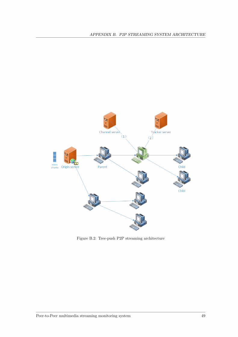
APPENDIX B. P2P STREAMING SYSTEM ARCHITECTURE
Figure B.2: Tree-push P2P streaming architecture
Peer-to-Peer multimedia streaming monitoring system 49
APPENDIX B. P2P STREAMING SYSTEM ARCHITECTURE
departures, the tree overlay has to be reconstructed because some nodes lost their data source [70].The peer communication in tree-based architecture is relatively simple. After tree structure
is formed, chunks are forwarded from the root of the tree to different levels of the tree hierarchy.The tree construction process is costive [31], but for peers in a constructed tree overlay, thecommunication overheads are very low [43]. Thus, the delay performance of tree-based system is,in general, good.
Tree-based P2P streaming system has a major drawback: it is vulnerable to peer churn. Peerchurn is a common phenomenon in P2P network, which means peers randomly joins or leaves theP2P network [43]. As we discussed, when an internal node leaves, the tree overlay needs to bereconstructed, which has a heavy cost [65]. Another disadvantage is inefficiency. As we can seefrom figure B.2, the leaf node in a tree does not contribute their upload capacities.
50 Peer-to-Peer multimedia streaming monitoring system
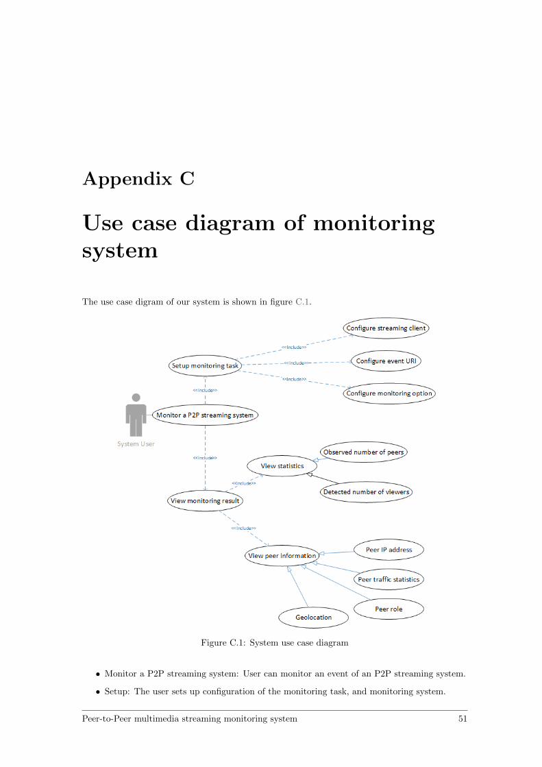
Appendix C
Use case diagram of monitoringsystem
The use case digram of our system is shown in figure C.1.
Figure C.1: System use case diagram
• Monitor a P2P streaming system: User can monitor an event of an P2P streaming system.
• Setup: The user sets up configuration of the monitoring task, and monitoring system.
Peer-to-Peer multimedia streaming monitoring system 51
APPENDIX C. USE CASE DIAGRAM OF MONITORING SYSTEM
– Configure streaming client: User configures the streaming client by indicating the nameof the target system in the configuration file. In addition, on each monitor host theuser needs to fill in a configuration file containing the paths to the installed clients.
– Configure event URI: User indicates the event URI. This parameter is only useful whenthe P2P client can accept the URI as a parameter to start.
– Configure monitoring option: User indicates the monitoring interval, logging optionand storage option.
• View monitoring results: The user views the result of the monitoring task.
– View statistics: The user views statistics including:
∗ Observed number of peers
∗ Detected number of viewers
∗ Country table (each entry has a number of peers and viewers)
From these statistics, the user can know the popularity of the monitored event.
– View peer information: The user views monitored peer’s information, including:
∗ IP address
∗ Role (viewer or a service node)
∗ Geographical location
∗ Traffic statistics
To conclude, in our monitoring system, the user can monitor a channel of an arbitrary P2Pstreaming service. From the monitoring result, the user can have information of geographicaldistribution of peers and peer’s role.
52 Peer-to-Peer multimedia streaming monitoring system
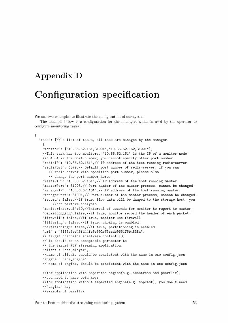
Appendix D
Configuration specification
We use two examples to illustrate the configuration of our system.
The example below is a configuration for the manager, which is used by the operator toconfigure monitoring tasks.
{
"task": [// a list of tasks, all task are managed by the manager.
{
"monitor": ["10.56.62.161,31001","10.56.62.162,31001"],
//This task has two monitors, "10.56.62.161" is the IP of a monitor node;
//"31001"is the port number, you cannot specify other port number.
"redisIP": "10.56.62.161",// IP address of the host running redis-server.
"redisPort": 6379,// Default port number of redis-server, if you run
// redis-server with specified port number, please also
// change the port number here.
"masterIP": "10.56.62.161",// IP address of the host running master
"masterPort": 31003,// Port number of the master process, cannot be changed.
"managerIP": "10.56.62.161",// IP address of the host running master
"managerPort": 31004,// Port number of the master process, cannot be changed.
"record": false,//if true, flow data will be dumped to the storage host, you
//can perform analysis
"monitorInterval":10,//interval of seconds for monitor to report to master,
"packetLogging":false,//if true, monitor record the header of each packet.
"firewall": false,//if true, monitor use firewall
"filtering": false,//if true, choking is enabled
"partitioning": false,//if true, partitioning is enabled
"uri" : "6183e6bc46fd44fc5c692c73ccde965175b4838a",
// target channel’s acestream content ID,
// it should be an acceptable parameter to
// the target P2P streaming application.
"client": "ace_player",
//name of client, should be consistent with the name in exe_config.json
"engine": "ace_engine"
// name of engine, should be consistent with the name in exe_config.json
//for application with separated engine(e.g. acestream and peerflix),
//you need to have both keys
//for application without seperated engine(e.g. sopcast), you don’t need
//"engine" key
//example of peerflix
Peer-to-Peer multimedia streaming monitoring system 53
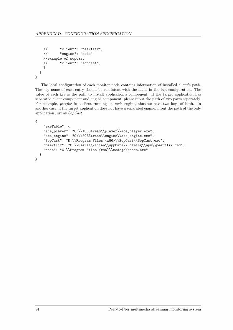
APPENDIX D. CONFIGURATION SPECIFICATION
// "client": "peerflix",
// "engine": "node"
//example of sopcast
// "client": "sopcast",
}
]
}
The local configuration of each monitor node contains information of installed client’s path.The key name of each entry should be consistent with the name in the last configuration. Thevalue of each key is the path to install application’s component. If the target application hasseparated client component and engine component, please input the path of two parts separately.For example, peerflix is a client running on node engine, thus we have two keys of both. Inanother case, if the target application does not have a separated engine, input the path of the onlyapplication just as SopCast.
{
"exeTable": {
"ace_player": "C:\\ACEStream\\player\\ace_player.exe",
"ace_engine": "C:\\ACEStream\\engine\\ace_engine.exe",
"SopCast": "D:\\Program Files (x86)\\SopCast\\SopCast.exe",
"peerflix": "C:\\Users\\Zijian\\AppData\\Roaming\\npm\\peerflix.cmd",
"node": "C:\\Program Files (x86)\\nodejs\\node.exe"
}
}
54 Peer-to-Peer multimedia streaming monitoring system

![Understanding Pull-based Method Efficiency in Peer …. Basic. Appl. Sci...CoolStreaming [5] and SopCast [6] has been very popular in the recent years. Moreover, BitTorrent [7] and](https://img.dokumen.tips/doc/110x75/5e3990f231af7327f13c0640/understanding-pull-based-method-efficiency-in-peer-basic-appl-sci-coolstreaming.jpg)
![GoalBit: The First Free and Open Source Peer-to-Peer ...goalbit.sourceforge.net/publications/lanc2009-20090717-CAMERAREADY.pdf · SopCast [12], created at the Fudan University of](https://img.dokumen.tips/doc/110x75/5e5981828b63d94fe12f391b/goalbit-the-first-free-and-open-source-peer-to-peer-sopcast-12-created-at.jpg)


![BEAM: A Peer-to-Peer Framework for Live Media Streamingpdarshan/BEAM/BEAM.pdf · content. New proprietary models like PPLive [2] and SOPCast [5] etc. that are similar to [6] have](https://img.dokumen.tips/doc/110x75/606fa20d58993523e6741481/beam-a-peer-to-peer-framework-for-live-media-pdarshanbeambeampdf-content.jpg)