Embed Size (px)
Citation preview

EGR Cooler Deposit Analysis
Michael J. Lance, John M.E. Storey and C. Scott Sluder
Oak Ridge National Laboratory
Brad Watkins, Michele Kaiser and Ayyappan Ponnaiyan
John Deere
Research sponsored by WFO sponsor John Deere under Contract DE-AC05-00OR22725 with UT-Battelle, LLC.
Techniques developed through a Department of Energy, Office
of Vehicle Technologies project sponsored by Jerry Gibbs.

2 Managed by UT-Battelle for the U.S. Department of Energy DEER 2011
Background: Exhaust Gas Recirculation Cooler Fouling
• High-pressure exhaust gas recirculation (EGR) is the dominant NOX-reduction technology. • Exhaust gas laden with PM flows through the EGR cooler which causes deposits to form
through thermophoresis and HC condensation. • The deposit thermal conductivity is very low, which reduces the effectiveness of the EGR
system. • EGR cooler fouling has become a significant issue for compliance with NOX emissions
standards and has negative impacts on cooler sizing and engine performance.

3 Managed by UT-Battelle for the U.S. Department of Energy DEER 2011
Experimental Approach
• 21 tube-in-shell EGR coolers were fouled using a 5-factor, 3-level design-of-experiments (DoE) with the following variables:
1. EGR flow rate 2. EGR inlet gas temperature 3. Soot (PM) level 4. Hydrocarbon (HC) concentration. 5. Coolant temperature
• A 9-liter engine and ULSD fuel were used to form the cooler deposits.
• Coolers were run until the effectiveness stabilized (typically 40-70 hours), were then cooled down to room temperature and then run for an additional few hours in order to measure the change in effectiveness (regeneration) due to shut down.
• Samples were cut and milled open and the mass per unit area of the deposit was measured as a function of distance down the tube.
• Microstructural analyses using both optical and electron microscopy were conducted to better understand deposition and removal processes.

4 Managed by UT-Battelle for the U.S. Department of Energy DEER 2011
Design of Experiments Summary
• Coolant Temperature had no effect on performance. • High EGR temperature always produced low HC.
DoE # EGR rate EGR Temp Smoke HC Coolant Temp1 L L L H L2 L L L L H3 L L H L L4 L L H H H5 L H L L L6 L H L L H7 L H H L L8 L H H L H9 H L L L L
10 H L L H H11 H L H H L12 H L H L H13 H H L L L14 H H L L H15 H H H L L16 H H H L H17 M L L L M18 M M M M M20 H M M M M21 M L M H M
Best Performing
Worst Performing
H = High L = Low M = Middle

5 Managed by UT-Battelle for the U.S. Department of Energy DEER 2011
Mass/Area: Measured at Inlet, Middle and Outlet
High EGR Temperature and High Flow
• The deposit mass decreases down the length of the cooler because as the gas is cooled, the thermophoretic velocity, which is proportional to the temperature gradient, decreases.
• Inlet had the highest mass except when both the EGR inlet temperature and flow rate was high.
Inle
t O
utle
t M
iddl
e

6 Managed by UT-Battelle for the U.S. Department of Energy DEER 2011
• There is always more deposit on the downstream side of the peak of the fin where the local residence time of the PM increases allowing for more deposition.
• Deposit removal can also occur on the upstream side.
Deposit Thickness Varies with Fin Geometry Outlet : Mid-Point Sample
DOE EGR rate EGR Temp Smoke HC18 M M M M
Deposit-Coated Bare Metal
Flow Direction
7 Managed by UT-Battelle for the U.S. Department of Energy DEER 2011
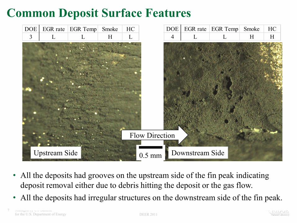
Common Deposit Surface Features
• All the deposits had grooves on the upstream side of the fin peak indicating deposit removal either due to debris hitting the deposit or the gas flow.
• All the deposits had irregular structures on the downstream side of the fin peak.
Downstream Side
DOE EGR rate EGR Temp Smoke HC4 L L H H
DOE EGR rate EGR Temp Smoke HC3 L L H L
Upstream Side 0.5 mm
Flow Direction

8 Managed by UT-Battelle for the U.S. Department of Energy DEER 2011
Effect of High Temperature (Inlet)
• All high temperature samples had mud-cracking at the inlet. • The cracks themselves will aid in heat transfer and may lead
to deposit spallation. • Thermochemical effects dominate the deposition and removal
mechanisms at these temperatures.
DOE EGR rate EGR Temp Smoke HC6 L H L L
DOE EGR rate EGR Temp Smoke HC8 L H H L
0.5 mm
Best Performing
Flow Direction

9 Managed by UT-Battelle for the U.S. Department of Energy DEER 2011
• High rate and high EGR temp correlated with a lower inlet mass. • Spalled regions are clearly observed. Once spallation occurs, fresh PM will deposit on
the bare metal. • This removal mechanism may be counteracting the higher mass expected at the inlet
under this high flow condition. Spallation is aided by the fast-flowing exhaust gas. • Metal surface appeared to be free of an HC film.
0.5 mm
DOE EGR rate EGR Temp Smoke HC14 H H L L
High Temp and High Flow Rate at Inlet DOE EGR rate EGR Temp Smoke HC
15 H H H L
Flow Direction
10 Managed by UT-Battelle for the U.S. Department of Energy DEER 2011
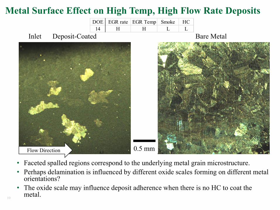
Metal Surface Effect on High Temp, High Flow Rate Deposits
• Faceted spalled regions correspond to the underlying metal grain microstructure. • Perhaps delamination is influenced by different oxide scales forming on different metal
orientations? • The oxide scale may influence deposit adherence when there is no HC to coat the
metal.
Bare Metal
DOE EGR rate EGR Temp Smoke HC14 H H L L
0.5 mm
Deposit-Coated Inlet
Flow Direction

11 Managed by UT-Battelle for the U.S. Department of Energy DEER 2011
Micron-sized Rounded Agglomerates in High Smoke Coolers
• Only carbon and oxygen were detected. • The agglomerates were present across the thickness. • Also found in the inlet diffuser.
DOE EGR rate EGR Temp Smoke HC8 L H H L Cross-section Inlet Cross-section

12 Managed by UT-Battelle for the U.S. Department of Energy DEER 2011
Highest HC Deposit Microstructure
• At least two layers are observed in the deposit: a dense HC layer coating the metal and a PM deposit with an HC gradient moving away from the metal.
• The presence of high amounts of HC appears to densify and coarsen the deposit producing mud-cracks.
• Can HC diffuse through the deposit?
DOE EGR rate EGR Temp Smoke HC10 H L L H Cross-section Cross-section Inlet
Peeled off of metal
0.25 mm Mud-cracks

13 Managed by UT-Battelle for the U.S. Department of Energy DEER 2011
Low HC Deposit Microstructure (Best Performing Cooler)
• The PM appears the same across the entire cross-section of the deposit.
• No HC gradient or high smoke agglomerates are observed. • After delamination, some PM remains on the metal which
suggests that, for these conditions, the weakest layer of the deposit is within the deposit, not at the deposit-metal interface.
DOE EGR rate EGR Temp Smoke HC6 L H L L Deposit-Metal Interface Deposit-Gas Interface
Metal

14 Managed by UT-Battelle for the U.S. Department of Energy DEER 2011
Four Worst Performing Coolers: High Rate & Low Temp
• High rate and low temperature deposits appeared much thicker. • The high rate introduces more PM and HC for deposition. • Low gas temperature turns off the spallation observed at the
inlet with high gas temperature.
DOE EGR rate EGR Temp Smoke HC12 H L H L11 H L H H10 H L L H9 H L L L
320
µm
0.25 mm
Inlet at Sine-Wave Peak

15 Managed by UT-Battelle for the U.S. Department of Energy DEER 2011
Summary
• Deposit mass and thickness was generally lowest at the outlet of the coolers due to a lower temperature gradient hence a lower thermophoretic velocity.
• Deposit mass and thickness was lowest on the upstream side of the peak of the fin for all of the coolers.
• EGR Temperature – Low EGR temperature combined with High EGR rate produces the most deposit. – High EGR temperature removes most (all?) HC on the metal surface which possibly reduces PM
adherence. – High EGR temperature produces thermochemical effects that correlates with deposit mud-
cracking. – Metal surface comes into play with high EGR temperature.
• EGR Rate – High EGR rate is bad because it increases the total PM and HC flowing into the cooler. – However, high EGR rate may be beneficial when combined with high EGR temp by aiding in
deposit removal at the inlet. • Smoke
– High smoke produces PM agglomerates. • HC
– High HC deposits have a dense HC layer on the metal and an HC gradient in the PM deposit. – In some cases, high HC may densify the deposit and produce mud-cracks though in a different
way than high EGR temp.