Embed Size (px)
Citation preview

Efficient Subgraph Isomorphism Detection:A Decomposition Approach
Bruno T. Messmer and Horst Bunke, Member, IEEE Computer Society
AbstractÐGraphs are a powerful and universal data structure useful in various subfields of science and engineering. In this paper, we
propose a new algorithm for subgraph isomorphism detection from a set of a priori known model graphs to an input graph that is given
online. The new approach is based on a compact representation of the model graphs that is computed offline. Subgraphs that appear
multiple times within the same or within different model graphs are represented only once, thus reducing the computational effort to
detect them in an input graph. In the extreme case where all model graphs are highly similar, the run-time of the new algorithm
becomes independent of the number of model graphs. Both a theoretical complexity analysis and practical experiments characterizing
the performance of the new approach will be given.
Index TermsÐGraph matching, graph isomorphism, subgraph isomorphism, preprocessing.
æ
1 INTRODUCTION
GRAPHS are a powerful and universal data structureuseful in various subfields of science and engineering.
When graphs are used for the representation of objects insome domain, the problem of comparing different objects toeach other can be formulated as the search for correspon-dences between the attributed graphs representing theobjects. Such correspondences can be established byisomorphism or subgraph isomorphism detection.
The concept of subgraph isomorphism detection hasbeen applied in a variety of fields. For example, it has beenused in chemical documentation systems for the compar-ison of molecular structures [1], in case-based-reasoning forthe retrieval of cases from the case base [2], [3], in semanticnetworks in combination with graph grammars [4], or inmachine learning, where it is used in order to learncommon substructures of different concepts [5], [6], [7],[8]. In pattern recognition, subgraph isomorphism detectionwas applied to Chinese character recognition [9], theinterpretation of schematic diagrams [10], [11], and sealverification [12]. It was also combined with evidence-basedsystems for shape analysis [13]. In computer vision,subgraph isomorphism detection was used for the localiza-tion of 3D objects in images [14], [15], [16], [17], [18] and inrobot vision [19].
The main problem with subgraph isomorphism detec-tion is the fact that it is an NP-complete problem [20]. Inother words, the time to detect a subgraph isomorphismbetween two graphs is in the worst case exponential in thenumber of vertices of these graphs. In the following, wegive a short review of methods for subgraph isomorphismdetection that have been proposed in the past.
The most common technique to establish a subgraphisomorphism is based on backtracking in a search tree. In
order to prevent the search tree from growing unnecessarilylarge, different refinement procedures such as the one byUllman [21], forward-checking and looking-ahead [22], ordiscrete relaxation [23] have been proposed. These techni-ques are fairly stable and perform well in most cases.Another approach is taken in [24], [25], where each possiblemapping of a vertex of the first graph onto a vertex of thesecond graph is recorded in an association graph and thedetection of a possible graph match is performed bymaximal clique detection. Finally, in [26], it is proposed topartition the graphs according to lattice theory in order toreduce the computational complexity of the subgraphisomorphism problem. All these methods provide anoptimal solution to the graph matching problem, but mayin the worst case become computationally intractable.
Continuous optimizations methods, on the other hand,aim at providing a solution within a reasonable time.However, they may not always find the optimal solution,i.e., the mapping of model graph vertices to input graphvertices found by a continuous optimization method notnecessarily represents a subgraph isomorphism. In [27], theadvantages and disadvantages of continuous optimizationmethods such as neural networks compared to the optimalbacktracking methods are examined. Other continuousoptimization approaches include the application of simu-lated annealing [28], genetic algorithms [29], [30], [31], andprobabilistic relaxation [32].
The methods for subgraph isomorphism detectionmentioned so far work on only two graphs at a time.However, in many applications there is more than onemodel graph that must be matched with the input graph.Consequently, it is necessary to apply the subgraphisomorphism algorithm to each model-input pair, resultingin a computation time that is linearly dependent on the sizeof the database. This dependency may become prohibitive ifthe number of model graphs is large. Hence, some form oforganization or indexing on the database of model graphs isneeded. In [33], [34], [35], [36], a hierarchical organization ofthe database is proposed which clusters the model graphsinto similarity classes. The given input graph is then used to
IEEE TRANSACTIONS ON KNOWLEDGE AND DATA ENGINEERING, VOL. 12, NO. 2, MARCH/APRIL 2000 307
. The authors are with the Institut fuÈr Informatik und angewandteMathematik, University of Bern, NeubruÈckstr. 10, CH-3012 Bern,Switzerland. E-mail: {messmer, bunke}@iam.unibe.ch.
Manuscript received 1 Dec. 1995; revised 30 Jan 1996; accepted 5 Mar. 1998.For information on obtaining reprints of this article, please send e-mail to:[email protected], and reference IEEECS Log Number 104345.
1041-4347/00/$10.00 ß 2000 IEEE
index the database of model graphs by traversing thehierarchy. However, such an indexing can only work if theinput graph is isomorphic to one of the model graphs. If the
input graph is larger than the models or contains more thanone instance of a model graph, the indexing process will notwork. Another hierarchical approach which does not havethis drawback was proposed in [37], where at the root of the
hierarchy there is a supergraph, consisting of differentsubgraphs of the model graphs. At run-time, the inputgraph is matched with the supergraph and the hierarchy is
traversed according to this initial match. The disadvantageof this method, however, is that the root graph may becomemuch larger than the individual model graphs and, thus,the first matching process may be more time consuming
than the sum of each individual subgraph isomorphismdetection process between a model graph and the input.Finally, some interesting approaches have been applied in
the domain of computer vision, where multilevel indexesare computed by precalculating all possible views of anobject into a view-description network [38], [39]. Thisnetwork can then be used to efficiently index the database
of model graphs. However, the scheme has not yet beengeneralized to arbitrary graphs.
Many of the reviewed algorithms above have interestingproperties. However, no technique has been described,which solves the problem of subgraph isomorphismdetection and the organization of large graph databases atthe same time for general labeled graphs. In this paper, wepropose a new approach to the problem of subgraphisomorphism detection from a set of model graphs to aninput graph. Our algorithm is somewhat similar to theRETE algorithm for forward-chaining, rule-based systems[40]. It is based on a compact representation of the modelgraphs. The representation is created offline by decompos-ing the model graphs into a set of subgraphs. Thesesubgraphs are the basic elements of the new representation.If a subgraph in the decomposition appears multiple timesin the same or in different model graphs, it is representedonly once. At run-time, the new representation is used toefficiently detect subgraph isomorphisms from the modelsto the input graph in the following manner. First, subgraphisomorphisms for the subgraphs in the representation aredetected. These subgraph isomorphisms are then recur-sively combined to form subgraph isomorphisms for thecomplete model graphs. Due to the fact that commonsubgraphs of different models are represented only once,they are matched exactly once with the input graph. Thus,the new algorithm is only sublinearly dependent on thenumber of the model graphs.
The rest of this paper is organized in the following manner:In Section 2, we provide basic definitions and notations. InSection 3, the new algorithm is described in detail. InSection 4, the computational complexity of the new algorithmis analyzed. The results of the theoretical complexity areconfirmed in a number of practical experiments documentedin Section 5. Finally, we conclude the paper with a summaryand some remarks on the applicability of the new algorithmin various domains. In Appendix A, Ullman's algorithmwhich is used as a benchmark in this paper is brieflydescribed, along with a computational complexity analysis.
2 DEFINITIONS AND NOTATIONS
The algorithms presented in this paper work on labeled
graphs. Let LV and LE denote the set of vertex and edge
labels, respectively.
Definition 1. A graph G is a 4-tuple G � �V ;E; �; ��, where
. V is the set of vertices,
. E � V � V is the set of edges,
. � : V ! LV is a function assigning labels to thevertices,
. � : E ! LE is a function assigning labels to the edges.
In this definition, the edges are directed, i.e., there is an
edge from v1 to v2, if �v1; v2� 2 E. For graphs with
undirected edges, we require �v2; v1� 2 E for any edge
�v1; v2� 2 E. The empty graph, i.e., the graph with an empty
set of vertices, will be denoted by ;.Definition 2. Given a graph G � �V ;E; �; ��, a subgraph of G
is a graph S � �Vs; Es; �s; �s� such that
1. Vs � V2. Es � E \ �Vs � Vs�3. �s and �s are the restrictions of � and � to Vs and Es,
respectively, i.e.,
�s�v� � ��v� if v 2 Vsundefined otherwise
�
�s�e� � ��e� if e 2 Es
undefined otherwise:
�From this definition, it is easy to see that given a graph G,
any subset of its vertices uniquely defines a subgraph of G.
We use the notation S � G to indicate that S is a subgraph
of G.
Definition 3. Given a graph G � �V ;E; �; �� and a subgraph
S � �Vs; Es; �s; �s� of G, the difference of G and S is the
subgraph of G that is defined by the set of vertices V ÿ Vs. We
denote the difference of G and S by Gÿ S.
Definition 4. Given two graphs G1 � �V1; E1; �1; �1�,G2 � �V2; E2; �2; �2�, where V1 \ V2 � ;, and a set of edges
E0 � �V1 � V2� [ �V2 � V1�with a labeling function � : E0 ! LE , the union of G1 and G2
with respect to E0 is the graph G � �V ;E; �; �� such that
1. V � V1 [ V2
2. E � E1 [ E2 [E03.
��v� � �1�v� if v 2 V1
�2�v� if v 2 V2
�
4.
��e� ��1�e� if e 2 E1
�2�e� if e 2 E2
��e� if e 2 E0
8<:
308 IEEE TRANSACTIONS ON KNOWLEDGE AND DATA ENGINEERING, VOL. 12, NO. 2, MARCH/APRIL 2000

The union of two graphs G1 and G2, with respect to a set ofedges E, according to Definition 4, will be denoted byG1 [E G2.
Definition 5. A bijective function f : V ! V 0 is a graphisomorphism from a graph G � �V ;E; �; �� to a graph G0 ��V 0; E0; �0; �0� if:
1. ��v� � �0�f�v�� for all v 2 V .2. For any edge e � �v1; v2� 2 E, there exists an edge
e0 � �f�v1�; f�v2�� 2 E0 such that ��e� � ��e0� andfor any e0 � �v01; v02� 2 E0 there exists an edge e ��fÿ1�v01�; fÿ1�v02�� 2 E such that ��e0� � ��e�.
Definition 6. An injective function f : V ! V 0 is a subgraphisomorphism from G to G0 if there exists a subgraph S � G0such that f is a graph isomorphism from G to S.
Notice that graph isomorphism is a special case of subgraphisomorphism. For the remainder of this paper, we willassume that there is a number of a priori known graphs, theso-called model graphs, and an input graph that is given online.The input and model graphs will be also referred to as inputand models, for short. The problem to be solved is to find allsubgraph isomorphisms from the models to the input.
3 DECOMPOSITION-BASED SUBGRAPH
ISOMORPHISM
3.1 Overview of the Method
Given a set of model graphs G1; . . . ; GN and an input graphGI , we want to find all subgraph isomorphisms from any ofthe models to the input graph. Under a naive strategy, wewould match the input graph sequentially to each modelusing, for example, Ullman's algorithm. The main dis-advantage of this approach is that it is linearly dependenton the number of model graphs. Moreover, it is inefficient ifdifferent model graphs have common substructures, be-cause these substructures will be matched with the inputgraph for each model repeatedly. In order to overcome thisinefficiency, we propose a different approach.
Instead of matching each model graph individually ontothe input graph, we recursively decompose the modelgraphs offline into smaller subgraphs. At run-time, thesesubgraphs are matched onto the input graph and alldetected subgraph isomorphisms are combined to formsubgraph isomorphisms for complete model graphs. Thisidea is similar to the RETE matching algorithm for forwardchaining production systems [40], [41]. The main advantageof this scheme is that subgraphs that appear multiple timesin the same or in different model graphs must be matchedonly once onto the input. Consequently, the correspondingsubgraph isomorphism detection process will be moreefficient than the sequential matching of the input graphwith each of the models.
The new approach consists of two parts. First, there is anoffline process in which the model graphs are recursivelydecomposed and the resulting subgraphs are representedby a special data structure. The second part is an onlineprocess, in which an input graph is matched with the modelgraphs, which are represented by the data structure
generated in the first step. In the following, we firstdescribe the offline decomposition of the model graphsand the data structure for their representation. Next, thenew subgraph isomorphism algorithm that is based on thisrepresentation and an example will be given.
3.2 Decomposing the Model Graphs
The main idea of the new approach is to recursivelydecompose the model graphs into smaller subgraphs in anoffline processing step. At run-time, the subgraph iso-morphism problem is solved in a divide-and-conquerfashion. That is, we first look for subgraph occurrences ofparts of the models in the input graph. All such occurrencesare then successively combined to form subgraph iso-morphisms for the complete models.
Definition 7. Let B � fG1; . . . ; GNg be a set of model graph. Adecomposition of B, D�B�, is a finite set of 4-tuples�G;G0; G00; E�, where
1. G;G0 and G00 are graphs with G0 � G and G00 � G2. E is a set of edges such that G � G0 [E G00.3. For each Gi there exists a 4-tuple �G;G0; G00; E� 2
D�B� with G � Gi; i � 1; . . . ; N .4. For each 4-tuple �G;G0; G00; E� 2 D�B� there exists no
other 4-tuple �G1; G01; G
001 ; E1� 2 D�B� with G � G1.
5. For each 4-tuple �G;G0; G00; E1� 2 D�B�a. if G0 consist of more than one vertex, then there
exists a 4-tuple �G1; G01; G
001 ; E1� 2 D�B� such
that G0 � G1
b. if G00 consists of more than one vertex then thereexists a 4-tuple �G2; G
02; G
002 ; E2� 2 D�B� such
that G00 � G2
c. if G0 consists of one vertex then there exists no4-tuple �G3; G
03; G
003 ; E3� 2 D�B� such that
G0 � G3
d. if G00 consists of one vertex then there exists no4-tuple �G4; G
04; G
004 ; E4� 2 D�B� such that
G00 � G4.
Informally speaking, a decomposition is a recursivepartitioning of graphs into smaller subgraphs, starting withcomplete models and terminating at the level of singlevertices. The first component in a 4-tuple �G;G0; G00; E� is thegraph to be decomposed, G0 and G00 are its two parts, and Eare the edges inG betweenG0 andG00 (see Conditions 1 and 2in Definition 7). Condition 3, in Definition 7, makes sure thatevery model in B is decomposed and Condition 4 impliesthat a decomposition is unique. By means of Condition 5, it isguaranteed that a decomposition is complete, i.e., theprocess of partitioning a graph into two parts is continueduntil individual vertices are reached. If several modelsGi;Gj; . . . have a common subgraph G, or if G occursmultiple times in one model Gi, it is sufficient to represent Gjust by one 4-tuple �G;G0; G00; E� in D�B�. This property notonly leads to a compact representation of a set of models, B,by means of the decomposition D�B�, but it also is the key toan efficient matching procedure at run-time.
The decomposition of a set of models will be used toguide the search for subgraph isomorphisms from themodels to the input. If there is a 4-tuple �G;G0; G00; E� inD�B�, then subgraph isomorphisms from G0 and G00 to the
MESSMER AND BUNKE: EFFICIENT SUBGRAPH ISOMORPHISM DETECTION: A DECOMPOSITION APPROACH 309

input will be searched for first. Once such subgraphisomorphisms have been found, they will be combined,whenever possible, into subgraph isomorphisms from G tothe input. This procedure is started with subgraphs G0 andG00 that consist of single vertices only and is recursivelycontinued until the level is reached where G represents acomplete model.
Apparently, there exist many different decompositionsfor a given set of models. This property holds even in thecase where the set of models consists of only a single graph.One could now define an optimal decomposition being, forexample, one that contains the minimum number of4-tuples, or one where the largest subgraph G that occursin all models is represented by a 4-tuple �G;G0; G00; E�.However, the computation of such an optimal decomposi-tion is a highly exponential problem [7]. In this paper, wepropose a decomposition algorithm which usually does notgenerate an optimal decomposition, but is computationallyinexpensive.
In Fig. 1, the algorithm decomposition is displayed. Theinput to the algorithm is a set B of models that are to bedecomposed and represented by the decompositionD�B�. Inthe beginning, D�B� is empty. The basic idea is tosequentially consider one model after the other and todecompose each model G such that subgraphs of previouslydecomposed model graphs are being reused for the decom-position of G. For this purpose, the procedure decomposegiven in Fig. 2 is called sequentially for each model graph G.Note that the decompositionD�B�ÐorD ifB is not explicitlymentionedÐis considered a global variable which retains its
contents for each call to decompose. The task of the proceduredecompose is to find the largest subgraph Smax in the modelgraph G that is already represented in D.1 If Smax isisormorphic to G, then G is already represented in D andthe algorithm exists. If G consists of a single vertex only, itcannot be decomposed any further and the algorithm exists.Otherwise, G is decomposed into Smax and Gÿ Smax.Clearly, Smax has been previously treated by the algorithmand, hence, only Gÿ Smax must be further decomposed bycalling the algorithm, recursively. If at some point in therecursion, no subgraph ofG is already respresented byD�B�,we randomly choose a subgraph Smax of G, for example, onethat consists of half the vertices of G for further decomposi-tion. Finally, the tuple (G;Smax;Gÿ Smax; E) is added to D.
Although the algorithm decomposition will usually notgenerate an optimal decomposition, it was shown in practicalexperiments that this has no significant influence on theperformance of the run-time algorithm (see Section 5). Veryimportant, however, is the fact that the algorithm decomposi-tion is incremental, i.e., given a setB of model graphs that arerepresented by the decomposition D�B�, a new model graphGN�1 can be added to the database by simply callingdecompose�GN�1�. Thus, D�B� can be updated incrementallywithout the need for a complete recomputation ofD�B� from
310 IEEE TRANSACTIONS ON KNOWLEDGE AND DATA ENGINEERING, VOL. 12, NO. 2, MARCH/APRIL 2000
Fig. 1. Algorithm decomposition.
Fig. 2. Procedure decompose.
1. In order to find the largest subgraph in G that is already represented, itis necessary to apply a subgraph isomorphism algorithm. As the decom-position is an offline process, some conventional algorithm such as Ullman'salgorithm may be used. However, for the complexity analysis in Section 4,we will assume that the new algorithm NA described in Section 3.3 isapplied in the decomposition process.

scratch. This is particularly of interest in applications where
large databases of graphs are involved and new model
graphs must be added to the database at run-time.
3.3 Subgraph Isomorphism Based on GraphDecomposition
The decomposition of a set of model graphs presented in
the Section 3.2 is the basis for an efficient algorithm thatdetects subgraph isomorphisms from a set of model graphs
to an input. Instead of matching each model individually
onto a given input, the new algorithm first finds all
occurrences of the individual vertices of the model in an
input graph. These occurrences are then recursively mergedinto larger structures until the level of complete model
graphs is reached. There are two basic problems that must
be solved in this scheme. First, as the smallest component of
a graph is a single vertex, there must be a procedure for thedetection of subgraph isomorphisms from single vertices to
an input graph. Secondly, given a decomposition D�B� and
a 4-tuple �G;G0; G00; E� 2 D�B�, if all subgraph isomorph-
isms from G0 and G00 to the input graph have been found,they must be combined into subgraph isomorphisms from
G to the input graph. For this purpose, a procedure for the
combination of subgraph isomorphisms is required.
In Fig. 3, the procedure vertex_test is given. It returns allmappings of a single vertex v with label l onto an inputgraph GI . The procedure simply consists of a loop over allvertices of GI in which the label of each input graph vertexvI is compared to the label of the model graph vertex v. Ifthe labels are identical then a subgraph isomorphism from v
to GI has been found and can be added to the set ofsubgraph isomorphisms F .
In Fig. 4, the procedure for the combination of subgraphisomorphisms is given. The procedure takes as input twographs S1; S2, an input graph GI , a set of edges E with acorresponding edge labeling function, and two sets offunctions F1; F2 which contain all subgraph isomorphismsfrom S1 and S2 to GI , respectively. Note that each edgee 2 E describes an edge between S1 and S2, i.e., e � �v1; v2�and v1 2 V1; v2 2 V2, or v1 2 V2; v2 2 V1. In order to combinetwo functions f1 2 F1 and f2 2 F2, there are two conditionsthat must be satisfied. First, the images of f1 and f2 must bedisjoint, i.e., f1�V1� \ f2�V2� � ;. Otherwise, the combinationof f1 and f2 will not be an injective function. Second, it mustbe ensured that each edge that is specified in the set E ismapped correctly onto edges in GI and vice versa. Thus, foreach edge e � �v1; v2� 2 E there must be an edge eI ��f1�v1�; f2�v2�� 2 EI and ��e� � �I�eI�. Also, for each edge
MESSMER AND BUNKE: EFFICIENT SUBGRAPH ISOMORPHISM DETECTION: A DECOMPOSITION APPROACH 311
Fig. 3. Procedure vertex_test.
Fig. 4. Procedure combine.
eI � �vI; v0I� 2 EI between f1�V1� and f2�V2� there must bean edge e � �fÿ1
1 �vI�; fÿ12 �v0I�� 2 E with �I�eI� � ��e�. If both
conditions are satisfied, the functions f1 and f2 can becombined into a subgraph isomorphism from S1 [E S2 tothe input. When all combinations of functions in F1 and F2
have been tested, the procedure terminates by outputtingthe set Fs of subgraph isomorphisms from the union graphS1 [E S2 to GI .
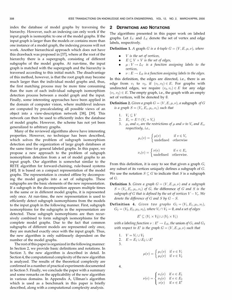
Based on the decomposition of a set of model graphs and
the procedures vertex_test and combine, we can formulate the
new subgraph isomorphism algorithm (Fig. 5). The input to
the algorithm consists of a decomposition D�B�, which
represents the model graphs B � fG1; . . . ; GNg and an
input graph GI . Informally speaking, the algorithm must
first search for subgraph isomorphisms from the smallest
components described in the decomposition D�B� to the
input graph GI and then gradually combine them into
larger subgraph isomorphisms. In order to keep track of the
components that have been matched already with the input
graph, each subgraph S; S0 or S00 occurring in a 4-tuple
�S; S0; S00; E� in D�B� can be marked with one of three
different tags. In the beginning, all subgraphs in the
decomposition are marked unsolved. As soon as a subgraph
has been tested for subgraph isomorphisms with the input
graph, it is either marked alive or dead. If the search for
subgraph isomorphisms was successful, then the subgraph
is marked alive and all detected subgraph isomorphisms are
associated with it. Otherwise, the subgraph is marked dead
and no subgraph isomorphisms are associated with it. First,
in Step 3a and Step 3b, the algorithm loops over all
components of the model graphs that consist of only one
vertex and calls the procedure vertex_test for each of these
components. Notice that if a vertexÐor, more precisely, a
particular vertex labelÐappears multiple times in the same
or different model graphs, the decomposition represents
this vertex only once and, thus, vertex_test is called exactly
once for this type of vertex. Next, in Steps 4a, 4b, 4c, and 4d,
each graph S is considered which is marked unsolved, but
decomposed into two subgraphs S1; S2 which have been
previously tested and successfully matched to the input
graph. The subgraph isomorphisms that are associated with
S1 and S2 are combined into possible subgraph isomorph-
isms for S by calling the procedure combine. If the set of
subgraph isomorphisms returned by combine is empty, then
S is marked dead and, consequently, for each model graph
which contains S as a subgraph, there exists no subgraph
isomorphism to the input graph. On the other hand, if the
returned set F of subgraph isomorphisms is not empty then
S is marked alive. This process continues until either all
4-tuples in D�B� have been tested or no 4-tuple can be
found in Step 4a for which both subgraphs are marked alive.
In this case, the search for further subgraph isomorphisms
can be terminated immediately. Finally, in Step 5, all
subgraph isomorphism that have been found for the model
graphs represented by D�B� are output.It is easy to see that the new algorithm finds all subgraph
isomorphisms from each of the model graphs G1; . . . ; GN tothe input graph GI . Furthermore, if a subgraph S is part ofseveral model graphs and represented by the decomposi-tion, i.e., there is a 4-tuple �S; S1; S2; E�, then the computa-tion of all subgraph isomorphisms from S to the inputgraph GI is done only once.
3.4 An Example
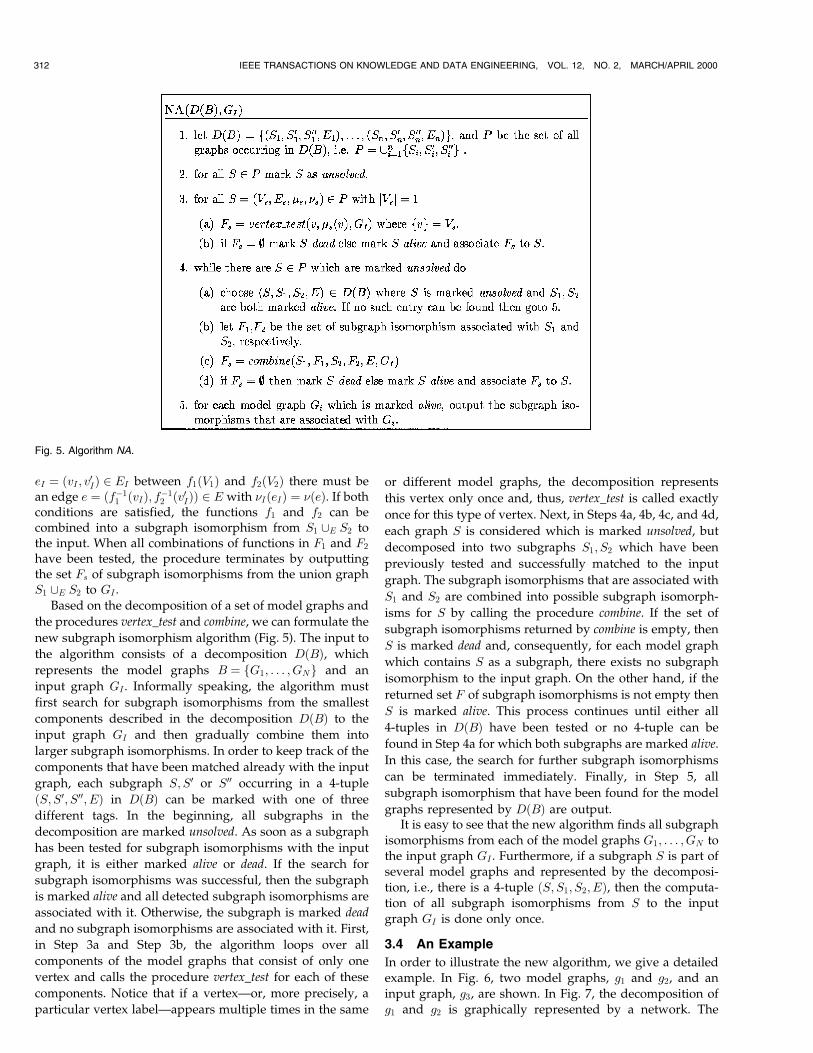
In order to illustrate the new algorithm, we give a detailedexample. In Fig. 6, two model graphs, g1 and g2, and aninput graph, g3, are shown. In Fig. 7, the decomposition ofg1 and g2 is graphically represented by a network. The
312 IEEE TRANSACTIONS ON KNOWLEDGE AND DATA ENGINEERING, VOL. 12, NO. 2, MARCH/APRIL 2000
Fig. 5. Algorithm NA.

network is displayed with vertices of the model graphs inthe top layer. Below are subgraphs of the models thatconsist of more than one vertex. The complete models arerepresented at the bottom of the network. The numbers tothe right of each network node are identifiers. At the top ofthe network, the five different vertex labels occurring in g1
and g2 are represented. Notice that, for example, the vertexwith label d represented in node 2 appears in both g1 and g2.It appears, however, only once in the decomposition. On thesecond level in Fig. 7, a subgraph that is decomposed intotwo vertices with label d and a, respectively, and an edgeconnecting them is represented. This subgraph occurs inboth g1 and g2. In network node 7, the largest commonsubgraph of g1 and g2 is represented. It is decomposed intothe subgraph represented in node 6, a vertex represented innode 4, and an edge. Finally, network nodes 8 and 9represent models g1 and g2, respectively.
At run-time, given the input graph g3, the algorithm NAdescribed in Section 3.3 first tries to find all subgraphisomorphisms for the vertices represented in the top nodesof the network. For example, the vertex labeled d can bematched onto the vertices 1 and 3 of g3. Consequently, thereare two subgraph isomorphisms associated with the node 2(denoted by f1g and f3g below the node 2 in Fig. 7). Next,for each subgraph in the decomposition whose componentshave already been successfully tested, the algorithm tries tocombine the subgraph isomorphisms of its components. Innode 6, the subgraph isomorphisms f1g and f3g associatedto node 2 and f2g and f6g associated to node 3 arecombined. However, only the combinations f12g and f32gare valid subgraph isomorphisms from the graph innetwork node 6 to the input graph g3. Because of theexistence of these two subgraph isomorphisms, networknode 6 is marked alive and, consequently, the subgraph innode 7 will be tested next. This process continues until a
single subgraph isomorphism, f1; 254g, has been foundfrom the graph g2 to the input graph g3. It can be easilyverified that no other subgraph isomorphism from either g1
or g2 to g3 exists.
4 COMPUTATIONAL COMPLEXITY ANALYSIS
In this section, we give a detailed analysis of the run-timecomplexity of the new algorithm for subgraph isomorphismdetection and of the algorithm for the decomposition of themodel graphs. The analysis will be based on the followingquantities:
N � the number of model graphs in the database,M1 � the number of vertices of a subgraph that is common
to all models,M2 � the number of vertices that are unique to each
model,M � the total number of vertices of a model graph, i.e.,
M �M1 �M2,I � the number of vertices in the input graph.
Due to the fact that the decomposition algorithm makesextensive use of some subgraph isomorphism algorithm(Step 3 in Fig. 2), its performance is strongly dependent onthe performance of the applied algorithm. For this reason,we first study the computational complexity of thesubgraph isomorphism algorithms and then examinecomplexity of the proposed decomposition algorithm.
In our analysis, we only consider the idealized situationwhere the model graphs have a single subgraph of size M1
in common. In practice, the situation will usually be morecomplicated due to the existence of subgraphs that arecommon to some, but not all models. Furthermore, forreasons of convenience, we assume that the model graphsare decomposed as follows: Given a model graph G and S,the subgraph of G which is common to all the graphs, weassume that the decomposition contains an entry�G;S;Gÿ S;E�. That is, the graph G is decomposed intothe common subgraph S and the difference graph Gÿ S.The graph S is then decomposed into a subgraph Si thatconsists of a single vertex and the difference graph S ÿ Si,which is again decomposed into a single vertex and theremaining difference graph. This process is continued untilthe difference graph itself consists of a single vertex only.The same decomposition scheme is applied to the graphGÿ S. Consequently, for a common subgraph of M1
vertices, there are M1 ÿ 1 4-tuples �S1; S01; S
001 ; E� where
S1; S01 and S001 are subgraphs of S. S1 consists of k, S01 of kÿ 1
and S001 of one vertex, k � 2; . . . ;M1. Analogously, there areM2 ÿ 1 4-tuples in the decomposition of the differencegraph Gÿ S, which consists of M2 vertices.2 Based on this,decomposition of the model graphs it is possible to analyzethe computational complexity of the new algorithm NAgiven in Fig. 5. The computation steps that are performedcan be estimated in terms of the number of calls to theprocedure vertex_test times the complexity of vertex_test,
MESSMER AND BUNKE: EFFICIENT SUBGRAPH ISOMORPHISM DETECTION: A DECOMPOSITION APPROACH 313
2. It must be mentioned that the algorithm decomposition given inSection 3.2 usually does not decompose the model graphs the way it isassumed here. However, the results of the complexity analysis wereconfirmed in a number of practical experiments documented in Section 5.
Fig. 6. Two model graphs g1; g2 and an input graph g3.
and the number of calls to the procedure combine times thecomplexity of combine itself. In Table 1, an overview of thetheoretical boundaries for both the new algorithm and, forcomparison reasons, Ullman's algorithm [21] is given. (Acomplexity analysis of Ullman's algorithm is given inAppendix A.)
The best case for both algorithms arises when each of thevertices of the model graphs is uniquely labeled. For a singlemodel graph, there will be M different vertices and conse-quently, the procedure vertex_test will be calledM times. Eachcall will test I vertices of the input graph and, thus, cause atotal number ofO�IM� steps. The number of matchings foundby vertex_test of a single model graph vertex onto the inputgraph will be bounded by O�I=M�. There will O�M� calls tothe procedure combine, i.e., for each 4-tuple �S1; S
01; S
001 ; E�
there will be a call combine�S01; F 01; S001 ; F 001 ; E;GI�, where S01consists of kÿ 1 and S001 of one vertex. Because all vertices areuniquely labeled, F 01 contains at most one subgraph iso-morphism and there will beO�I=M� subgraph isomorphismsin F 001 . In the procedure combine, each mapping in F 01 iscombined with each mapping inF 001 . Comparing the images ofthe mappings takesO�k� steps and testing each edge betweenS01 and S001 takes O�k� steps with k �M. Thus, the totalcomputational complexity for matching a single model graphagainst an input graph is in the best case bounded by:
O�IM �M2I=M� � O�IM�: �1�When N model graphs must be matched onto the inputgraph, there will be O�IM1� steps performed for thecommon subgraph S and O�NIM2� steps for each differ-ence graph Gi ÿ S of the N model graphs. Additionally, foreach model graph the subgraph isomorphisms found forthe common subgraph and the difference graph must becombined, requiring O�NM1M2� steps at most. Thus, thecomputational complexity of the new algorithm for finding
all subgraph isomorphisms from N model graphs to aninput graph is in the best case bounded by:
O�IM1 �NIM2 �NM1M2�: �2�In the extreme case where there is no common subgraphamong the model graphs, i.e., M1 � 0 and M2 �M, thecomplexity is bounded by:
O�NIM�: �3�On the other hand, in the limit when all models areidentical, i.e., M1 �M and M2 � 0, the complexity of thenew algorithm becomes independent of the number ofmodels and is only bounded by:
O�IM�: �4�The worst case for both the new and the traditional
algorithm arises when all vertices in the model graphs havethe same label and each vertex is connected to each othervertex. Given a single model graph, the new algorithmmakes only one call to the procedure vertex_test as there isonly one vertex label. Each of the model vertices is thensuccessfully matched onto O�I� input graph vertices and,consequently, there are O�I� subgraph isomorphism re-turned by vertex_test. These subgraph isomorphisms con-stitute the input to the first call of the procedure combine inwhich O�I2� subgraph isomorphisms are found at theexpense of O�M� steps. Next, according to the decomposi-tion described at the beginning of this section, there will beM calls to combine. For each call, the number of subgraphisomorphisms that must be combined will be increased by afactor of I. Consequently, the total number of steps for asingle model graph amounts in the worst case to
O�I �MIMM� � O�IMM2�: �5�
314 IEEE TRANSACTIONS ON KNOWLEDGE AND DATA ENGINEERING, VOL. 12, NO. 2, MARCH/APRIL 2000
Fig. 7. Decomposition of graphs g1; g2 from Fig. 6 displayed as a network structure.

For a database of N model graphs, the total effort is the sumof the effort for testing the common subgraph and the effortfor testing the subgraphs that are unique to each modelgraph. The common subgraph is tested exactly once at theexpense of O�IM1M2
1 �, while the unique subgraph must betested for each model graph individually at the expense ofO�IM2M2
2 �. By adding O�NM1M2IM� steps necessary for the
combination of the subgraph isomorphisms, we arrive at atotal complexity for N model graphs of
O�IM1 M21 �NIM2 M2
2 �NM1M2IM�: �6�
In the extreme case, when the database consists of completelydifferent model graphs only, i.e.,M1 � 0;M2 �M, the aboveformula becomes
O�NIMM2�: �7�On the other hand, if all models are identical, i.e.,M1 �M;M2 � 0, the size of the database, N , disappearsin (6) and the worst case complexity of the new algorithmbecomes
O�IMM2�: �8�When compared to the computational complexity ofUllman's algorithm given in the second column of Table 1,we note that both in the best and worst case the newalgorithm is faster than the traditional algorithm by a factorof N for similar model graphs in the limit. On the otherhand, given a set of completely disjoint model graphs bothalgorithms have the same computational complexity. Inpractice, we can expect the computational complexitysomewhere between O�IM� and O�NIMM2�.
While the run-time complexity of the new subgraphisomorphism algorithm is of general importance, thecomplexity of the decomposition algorithm is only relevantto applications which cannot neglect the time spent forpreprocessing. For example, in applications where somemodels are known beforehand, but others are only acquiredat run-time, the time spent for decomposing and adding thenew models to the existing decomposition may berestricted. Thus, the performance of the decompositionalgorithm will become important.
Given a set of models B � fG1; . . . ; GNg and a decom-position D�B� of B, a new model G is decomposed andadded to D�B� by calling the procedure decompose(G). Thebasic idea of this procedure is to find a tuple �Gi;G
0i; G
00i ; E�
in D�B� such that Gi is a subgraph of G and maximal inD�B�. In case of success, the model G is decomposed into Gi
and the difference graph GÿGi which will be decomposeditself by recursively calling the procedure decompose.Clearly, the computational complexity of the decompositionprocess depends on the number of calls to decompose and thecomplexity of the search for the largest subgraph indecompose. It is easy to see that for a graph G withM vertices, any decomposition of G consists of at mostO�2M� � O�M� subgraphs. As each of these subgraphsmust be decomposed itself (unless it is already representedin D�B�) the number of calls to decompose is at most O�M�.In each call to decompose, a search for the largest subgraph ofG that is already represented in D�B� is performed. Thissearch process requires that for each tuple �Gi;G
0i; G
00i ; E� in
D�B� a subgraph isomorphism from Gi to G is computed.Apparently, if these subgraph isomorphisms are computedwith a conventional algorithm such as Ullman's algorithm,then the complexity of the search process will be linearlydependent on the number of tuples in D�B�. However, dueto the fact that the algorithm NA was especially designed tosolve the subgraph isomorphism problem based on adecomposition of the model graphs, it can also be appliedin the decomposition algorithm itself. That is, given adecomposition D�B� and a model graph G, the decomposi-tion algorithm calls the algorithm NA in order to find allsubgraph isomorphisms from graphs in D�B� to G.Consequently, the computational complexity of the searchprocess in decompose depends on the computational com-plexity of the new algorithm NA (see Table 1). Note that thenumber of vertices in the input graph is denoted by I inTable 1. However, when NA is applied in the decomposi-tion algorithm, the input graph is in fact a model graph and,therefore, I �M. This means that in the best case, when allthe models are identical and their vertices are uniquelylabeled, the number of steps performed in decompose isbounded by O�M2� (see (4)). As there are O�M� recursivecalls to decompose the total number of steps for the
MESSMER AND BUNKE: EFFICIENT SUBGRAPH ISOMORPHISM DETECTION: A DECOMPOSITION APPROACH 315
TABLE 1Best and Worst Case Complexities of the New and the Traditional Algorithm
decomposition of a model graph with M vertices is in thebest case bounded by O�M3�. Notice that in order todecompose a complete set of model graphs from scratch,the procedure decompose is sequentially called for each ofthese models. Thus, in the best case, the computationalcomplexity for decomposing a set of N models is boundedby:
O�NM3�: �9�From the previous complexity analysis of the algorithm
NA, we know that the worst case arises when all the graphsare completely different and the vertices of each graph areidentically labeled. Thus, according to the worst casecomplexity of algorithm NA given in (7), the number ofsteps in decompose is bounded by O�NIMM2� � O�NMM�2�for I �M. As there are O�M� subgraphs in a decompositionof a model with M vertices, the computational complexityof the decomposition algorithm is in the worst casebounded by O�NMM�3�. Again, if there is a set of modelsthat must be decomposed from scratch, the proceduredecompose will be called for each of these models individu-ally and the worst case complexity will be bounded by:
O�N2MM�3�: �10�Notice that in spite of the exponential worst case complexityof the proposed decomposition algorithm, it is ourexperience that it performs reasonably well for mostapplications (see Section 5).
5 EXPERIMENTAL RESULTS
In order to examine the performance of the new algorithmin practice, we have performed a number of experimentswith randomly generated graphs. The new algorithm (NA)and Ullman's refinement procedure (UA) were bothimplemented in C++ and run on a SUN Sparc10 Work-station. The code of NA consists of roughly 7,000 linescompared to 2,500 lines of UA.
All model and input graphs were randomly generated.The parameters in the random graph generation processwere:
. the number of vertices,
. the number of edges,
. the number of different vertex labels (all edges wereunlabeled and undirected),
. the number of graphs in the database,
. the size of the common subgraph that was containedin all models.
In our experiments, we automatically generated modelgraphs based on these parameters. From each model graph,a corresponding isomorphic input graph was derived bycopying and permuting its vertices and edges. Both NA andUA were then used to detect all graph isomorphisms fromthe models to the inputs. In order to account for the randomnature of the underlying graphs, each experimental run wasrepeated ten times and the average computation time wasrecorded as a result. By varying different parameters in thegraph generation process, the behavior of the newalgorithm was studied. In Table 2, an overview of theexperiments is given, indicating the different parametervalues used in each specific experiment.
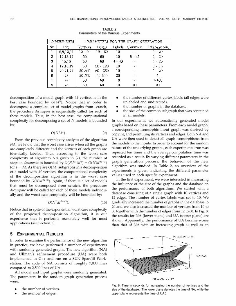
In the first experiment, we were interested in measuringthe influence of the size of the graphs and the database onthe performance of both algorithms. We started with adatabase consisting of a single graph with 10 vertices and12 edges. The number of vertex labels was set to 10. Wegradually increased the number of graphs in the database to20 and we also increased the number of vertices from 10 to50 together with the number of edges from 12 to 60. In Fig. 8,the results for NA (lower plane) and UA (upper plane) areshown. Apparently, the performance of UA became worsethan that of NA with an increasing graph as well as an
316 IEEE TRANSACTIONS ON KNOWLEDGE AND DATA ENGINEERING, VOL. 12, NO. 2, MARCH/APRIL 2000
TABLE 2Parameters of the Various Experiments
Fig. 8. Time in seconds for increasing the number of vertices and the
size of the database. (The lower plane denotes the time of NA, while the
upper plane represents the time of UA.)
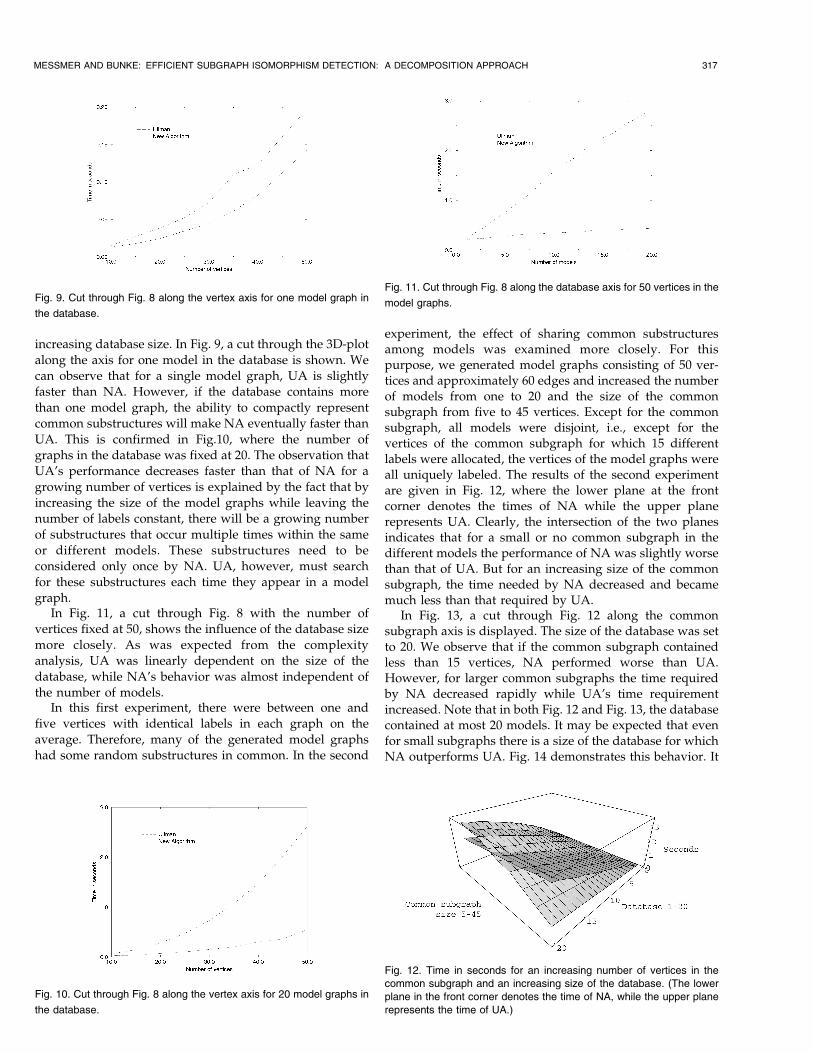
increasing database size. In Fig. 9, a cut through the 3D-plotalong the axis for one model in the database is shown. Wecan observe that for a single model graph, UA is slightlyfaster than NA. However, if the database contains morethan one model graph, the ability to compactly representcommon substructures will make NA eventually faster thanUA. This is confirmed in Fig.10, where the number ofgraphs in the database was fixed at 20. The observation thatUA's performance decreases faster than that of NA for agrowing number of vertices is explained by the fact that byincreasing the size of the model graphs while leaving thenumber of labels constant, there will be a growing numberof substructures that occur multiple times within the sameor different models. These substructures need to beconsidered only once by NA. UA, however, must searchfor these substructures each time they appear in a modelgraph.
In Fig. 11, a cut through Fig. 8 with the number ofvertices fixed at 50, shows the influence of the database sizemore closely. As was expected from the complexityanalysis, UA was linearly dependent on the size of thedatabase, while NA's behavior was almost independent ofthe number of models.
In this first experiment, there were between one andfive vertices with identical labels in each graph on theaverage. Therefore, many of the generated model graphshad some random substructures in common. In the second
experiment, the effect of sharing common substructuresamong models was examined more closely. For thispurpose, we generated model graphs consisting of 50 ver-tices and approximately 60 edges and increased the numberof models from one to 20 and the size of the commonsubgraph from five to 45 vertices. Except for the commonsubgraph, all models were disjoint, i.e., except for thevertices of the common subgraph for which 15 differentlabels were allocated, the vertices of the model graphs wereall uniquely labeled. The results of the second experimentare given in Fig. 12, where the lower plane at the frontcorner denotes the times of NA while the upper planerepresents UA. Clearly, the intersection of the two planesindicates that for a small or no common subgraph in thedifferent models the performance of NA was slightly worsethan that of UA. But for an increasing size of the commonsubgraph, the time needed by NA decreased and becamemuch less than that required by UA.
In Fig. 13, a cut through Fig. 12 along the commonsubgraph axis is displayed. The size of the database was setto 20. We observe that if the common subgraph containedless than 15 vertices, NA performed worse than UA.However, for larger common subgraphs the time requiredby NA decreased rapidly while UA's time requirementincreased. Note that in both Fig. 12 and Fig. 13, the databasecontained at most 20 models. It may be expected that evenfor small subgraphs there is a size of the database for whichNA outperforms UA. Fig. 14 demonstrates this behavior. It
MESSMER AND BUNKE: EFFICIENT SUBGRAPH ISOMORPHISM DETECTION: A DECOMPOSITION APPROACH 317
Fig. 9. Cut through Fig. 8 along the vertex axis for one model graph in
the database.
Fig. 10. Cut through Fig. 8 along the vertex axis for 20 model graphs in
the database.
Fig. 11. Cut through Fig. 8 along the database axis for 50 vertices in the
model graphs.
Fig. 12. Time in seconds for an increasing number of vertices in thecommon subgraph and an increasing size of the database. (The lowerplane in the front corner denotes the time of NA, while the upper planerepresents the time of UA.)

shows a cut through Fig. 12 along the database axis with thecommon subgraph size set to five vertices. As an extensionof the results shown in Fig. 12, the size of the database wasvaried between 1 and 40. For a database size of 30 models,the run-time of the two algorithms was identical and forlarger databases NA performed better than UA. Thisindicates that NA is more efficient than UA even for smallcommon subgraphs provided that the number of models inthe database is sufficiently large.
In the first and second experiment, we always kept thenumber of vertex labels constant. In the third experiment,this number was varied. All generated graphs contained50 vertices and 60 edges. The number of vertex labels grewfrom 1 to 40 and again, we increased the size of the databasefrom 1 to 20. The results are displayed in Fig. 15. The lower(upper) plane in the right corner corresponds to NA (UA). Itcan be observed that the two planes intersect each other.That is, the performance of NA became worse than that ofUA when less than five labels were present. The line ofintersection of the two planes grows with the number ofgraphs in the database as expected. In Fig. 16, a cut throughFig. 15 along the axes for the labels is shown, with thedatabase size set to 10. Between 10 and 40 labels, theperformance of NA and UA changed only minimally andNA was always faster. However, for less than five labels,NA took much more time to finish than UA. The worst caseemerged for NA when there was only one vertex label, i.e.,all vertices were identically labeled. In this case, NArequired an average of 12 minutes in order to detect allgraph matches. This decrease in the performance of NA is
due to the fact that for unlabeled graphs, the number ofmatches that are found for small subgraphs of the modelgraphs is usually very large. Thus, the concept of the newalgorithm to first test the smaller components of the modelgraphs and then to combine them into subgraph isomorph-isms for larger components is a major disadvantage whenthe underlying graphs are unlabeled. Consequently, theworst case behavior, as described in the complexity analysissection can be observed in Fig. 15 and Fig. 16. Obviously,NA tends towards the worst case behavior faster than UAfor a decreasing number of labels.
In the fourth experiment, the influence of the connectiv-ity, i.e., the number of edges in a graph, was examined. Inall of the previous experiments, the average degree of eachvertex was kept at 2:5. For the experiment documented inFig. 17, the graphs consisted of 50 vertices, 10 vertex labels,and a gradually increasing number of edges, starting at 50and ending at 120. Similar to the previous experiments, wealso varied the number of models in the database from 1 to10. In Fig. 17, the lower plane (upper plane) in the leftcorner denotes the times of NA (UA). Apparently, theperformance of NA decreased with a growing number ofedges in the graphs. In Fig. 18, a cut through Fig. 17 is takenalong the axis denoting the number of edges with thenumber of graphs in the database fixed at 10. There waspractically no influence of the number of edges on theperformance of UA in the considered range. However, thecomputation time of NA increased fast with the number ofedges. This behavior is due to the fact that with a high
318 IEEE TRANSACTIONS ON KNOWLEDGE AND DATA ENGINEERING, VOL. 12, NO. 2, MARCH/APRIL 2000
Fig. 13. Cut through Fig. 12 along the common subgraph axis with the
size of the database set to 20.
Fig. 14. Cut through Fig. 12 along the database axis with the size of the
common subgraph set to 5.
Fig. 15. Time in seconds for increasing number of labels and size of the
database. (The lower plane in the right corner denotes time of NA while
the upper plane represents UA.)
Fig. 16. Cut through Fig. 15 along the labels axis with 10 model graphs
in the database.

connectivity, the number of small subgraphs of a graph thatcan be matched onto themselves is large. On the other hand,the tendency of UA to spend more time than NA for largerdatabases was again confirmed in Fig. 19, where a cut ofFig. 17 along the axis denoting the size of the database isshown. The number of edges was constantly set to 100. Weobserve that for less than seven models in the database, NAwas slower than UA. For more than seven models, thesharing of common subgraphs in NA and the lineardependency of UA on the size of the database resulted inUA taking more time than NA.
While in the first four experiments, we examined thebehavior of NA for the case of graph isomorphism, the fifthexperiment was especially devoted to subgraph isomorph-ism detection. The models generated for this experimentconsisted of 50 vertices, 10 different vertex labels, and60 edges. For each model graph, a corresponding input graphwas created by copying the model and subsequently adding agrowing number of vertices and edges. Thus, it was ensuredthat there existed at least one subgraph isomorphism from themodel to the input. The number of additional vertices in theinput graph was varied between 0 and 250, i.e., in thebeginning, the input graphs consisted of 50 and in the end of300 vertices. At the same time, the number of models in thedatabase was also increased from 1 to 20. The results of the
fifth experiment are given in Fig. 20. Note that the lower planein the left corner denotes the time of NA while the upper planerepresents UA. As expected, both NA and UA used more timefor a growing input graph and a growing database. However,while UA performed better than NA when there were onlyfew models in the database, the linear dependency on thedatabase size caused UA to take more time than NA whenthere were more than ten models. In Fig. 21, a cut through Fig.20 along the axis of the input graph for a database containingone model is given. It confirms that NA did not perform aswell as UA for finding all subgraph isomorphisms from amodel to a growing input graph. On the other hand, in Fig. 22,a cut through Fig. 20 along the database axis with the inputgraph constantly set to 300 vertices reveals that due to thecompact representation of the models, NA used less time thanUA when the database size was increased.
In all the experiments documented so far, the perfor-mance of UA and NA were studied for model graphs anddatabases of moderate sizes. The next two experimentswere devoted to testing the behavior of both algorithms forvery large graphs on the one hand and very large databaseson the other hand. In Fig. 23, the size of the model and inputgraph was increased from 50 to 500 vertices along with thenumber of edges that was increased from 60 to 600 edges.There were 30 different vertex labels used, i.e., for a graphwith 300 vertices there were on the average 10 vertices withthe same label. The database consisted of a single modelgraph. We can observe that the performance of UAdecreased much faster than NA's performance. While UAmatched graphs with 250 vertices within 30 seconds, NAwas capable of matching graphs twice as large in the sametime. This behavior can again be explained by the fact thatwith an increasing number of vertices (and a constantnumber of labels) the number of substructures that appearmultiple times inside the same model graph grows.Although the algorithm decomposition that was proposedfor the offline decomposition of the models usually does notdetect all of these substructures and represents them onlyonce, the resulting decomposition is still fairly compact andallows NA to perform better than UA. Most important,however, is that decomposition is computationally inexpen-sive. For example, the decomposition of a graph with 50
MESSMER AND BUNKE: EFFICIENT SUBGRAPH ISOMORPHISM DETECTION: A DECOMPOSITION APPROACH 319
Fig. 17. Time in seconds for increasing number of edges and size of the
database. (The lower plane in the left corner denotes the time of NA
while the upper plane represents UA.)
Fig. 18. Cut through Fig. 17 along the edges axis with 10 model graphs
in the database.
Fig. 19. Cut through Fig. 17 protect along the database axis with 100
edges in the model graphs.

vertices and 60 edges took only 0.21 seconds, and for agraph with 500 vertices and 600 edges only 70 seconds wererequired (not documented here).
Next, in Fig. 24, the number of model graphs in thedatabase was increased from 1 to 100. As in the very firstexperiment (Fig. 8) the graphs consisted of 50 vertices and60 edges with 10 vertex labels. Note that with NA evenlarge databases remain tractable (about 1 second) while UArequires time that is linearly dependent on the database(15 seconds for 100 models).
Finally, in the eighth experiment, we studied theinfluence of the decomposition algorithm on the perfor-mance of NA. In Section 3.2, it was observed that thereexists a large number of different decompositions of a set ofmodel graphs. These decompositions differ in terms ofcompactness and also in terms of the run-time performanceof NA. For example, it can be hypothesized that the optimaldecomposition, i.e., the decomposition which contains a4-tuple �Gc;G
0c; G
00c ; Ec� for the largest subgraph Gc that
appears in all the model graphs, will guarantee the optimalrun-time performance of NA. However, as mentionedbefore, the computation of the optimal decomposition is ahighly exponential task. Thus, in Section 3.2, we proposed
the algorithm decomposition which is computationallyinexpensive. The drawback of this algorithm, however, isthat it does not necessarily generate an optimal decomposi-tion for a given set of models. Furthermore, as the modelsare treated sequentially, the resulting decomposition isdependent on the order of the models in the database. Inorder to study the difference in the performance of NA foran optimally decomposed database of models, on the onehand, and for a nonoptimal decomposition of the samedatabase on the other hand, the following experiment wasperformed. We generated a database containing 20 modelgraphs, each consisting of 50 vertices, 60 edges, and10 different vertex labels. Furthermore, a subgraph Gc with30 vertices and 40 edges that appeared in all the modelgraphs was explicitly defined. Thus, it was possible tosimulate the result of an optimal decomposition algorithmby taking the largest common subgraph Gc directly from thegraph generation process. The input graphs were iso-morphic copies of the model graphs. The performance ofNA for detecting all graph isomorphisms from the modelsto the inputs based on this optimal decomposition wascompared to its performance when the proposed, non-optimal algorithm decomposition was applied. In Fig. 25, the
320 IEEE TRANSACTIONS ON KNOWLEDGE AND DATA ENGINEERING, VOL. 12, NO. 2, MARCH/APRIL 2000
Fig. 20. Time in seconds for increasing number of vertices in the input and size of the database. (The lower plane in the left corner denotes the time
of NA while the upper plane represents UA.)
Fig. 21. Cut through Fig. 20 along the input graph axis with 1 model in
the database.
Fig. 22. Cut through Fig. 20 along the database axis with 300 vertices in
the input graph.
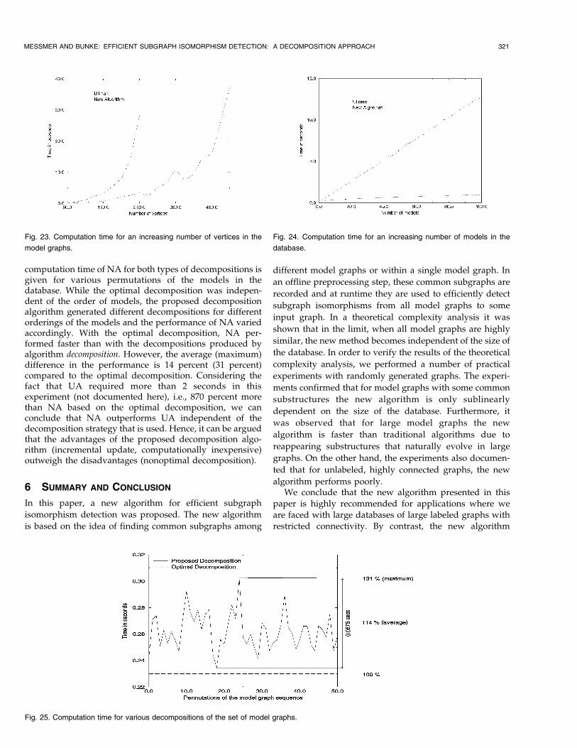
computation time of NA for both types of decompositions isgiven for various permutations of the models in thedatabase. While the optimal decomposition was indepen-dent of the order of models, the proposed decompositionalgorithm generated different decompositions for differentorderings of the models and the performance of NA variedaccordingly. With the optimal decomposition, NA per-formed faster than with the decompositions produced byalgorithm decomposition. However, the average (maximum)difference in the performance is 14 percent (31 percent)compared to the optimal decomposition. Considering thefact that UA required more than 2 seconds in thisexperiment (not documented here), i.e., 870 percent morethan NA based on the optimal decomposition, we canconclude that NA outperforms UA independent of thedecomposition strategy that is used. Hence, it can be arguedthat the advantages of the proposed decomposition algo-rithm (incremental update, computationally inexpensive)outweigh the disadvantages (nonoptimal decomposition).
6 SUMMARY AND CONCLUSION
In this paper, a new algorithm for efficient subgraph
isomorphism detection was proposed. The new algorithm
is based on the idea of finding common subgraphs among
different model graphs or within a single model graph. In
an offline preprocessing step, these common subgraphs are
recorded and at runtime they are used to efficiently detect
subgraph isomorphisms from all model graphs to some
input graph. In a theoretical complexity analysis it was
shown that in the limit, when all model graphs are highly
similar, the new method becomes independent of the size of
the database. In order to verify the results of the theoretical
complexity analysis, we performed a number of practical
experiments with randomly generated graphs. The experi-
ments confirmed that for model graphs with some common
substructures the new algorithm is only sublinearly
dependent on the size of the database. Furthermore, it
was observed that for large model graphs the new
algorithm is faster than traditional algorithms due to
reappearing substructures that naturally evolve in large
graphs. On the other hand, the experiments also documen-
ted that for unlabeled, highly connected graphs, the new
algorithm performs poorly.We conclude that the new algorithm presented in this
paper is highly recommended for applications where weare faced with large databases of large labeled graphs withrestricted connectivity. By contrast, the new algorithm
MESSMER AND BUNKE: EFFICIENT SUBGRAPH ISOMORPHISM DETECTION: A DECOMPOSITION APPROACH 321
Fig. 23. Computation time for an increasing number of vertices in the
model graphs.
Fig. 24. Computation time for an increasing number of models in the
database.
Fig. 25. Computation time for various decompositions of the set of model graphs.
should not be applied to problems dealing with unlabeled,highly connected graphs, to databases of completelydisjoint graphs, or to problems where the input graph isconsiderably larger than the model graphs. We feel that thenew algorithm is a substantial contribution to the problemof efficient subgraph matching. The algorithm has beenpresented in a general form without the explicit use ofdomain features or heuristics. Therefore, it can be regardeda generic tool that is applicable to various tasks. Theextension of the new algorithm to error-tolerant subgraphisomorphism detection is currently under investigation. Atlast, it is to be mentioned that there is a potential forparallelization inherent in the new approach, which may beused for a further improvement of the performance [42].
APPENDIX A
COMPLEXITY OF ULLMAN's ALGORITHM
In order to understand the complexity analysis of Ullman'salgorithm [21] given in this appendix, we first briefly describethe algorithm itself. The basic idea of Ullman's algorithm is totake one vertex of a model after the other and map it onto theinput vertices such that the resulting mapping represents asubgraph isomorphism according to Definition 6. If, at somepoint in the algorithm, the mapping does not represent asubgraph isomorphism then the algorithm backtracks andtries another mapping. Formally, given a model G ��V ;E; �; �� and an input GI � �VI; EI; �I; �I�, the first vertexv1 in V is mapped to some vertex wi in VI . If ��v1� � �I�wi�then the partial mapping f�v1; wi�g represents a subgraphisomorphism and the algorithm continues with the secondvertex v2 in V . Clearly, v2 cannot be mapped to wi because wiis already mapped to by v1. Thus, v2 is mapped to some inputvertex wj in VI ÿ fwig. If ��v2� � �I�wj� and, furthermore, iffor each edge e � �v1; v2� 2 E there exists a correspondingedge eI � �wi; wj� 2 EI with ��e� � ��eI� then the partialmapping f�v1; wi�; �v2; wj�g represents a subgraph isomorph-ism from the subgraph of G induced by the vertices v1; v2 tothe inputGI . This process is continued until either all verticesv1; . . . ; vM in V are successfully mapped onto VI and asubgraph isomorphism from G to GI is found or until forsome vertex vn, no corresponding vertex in VI ÿfwi; wj; . . . ; wkg exists, with fwi; wj; . . . ; wkgbeing the verticesin VI that are mapped to by v1; v2; . . . ; vnÿ1. In both cases, thealgorithm backtracks to a previous vertex of G and tries toremap it. Although this algorithm finds all subgraphisomorphisms from a small model to a small input graph inreasonable time, it performs poorly when the underlyinggraphs become larger. One of the reasons for this behavior isthat the algorithm only tests for the subgraph isomorphismconditions in the partial mapping, but does not consider thevertices of the model that have not yet been mapped. In orderto overcome this problem, Ullman proposed a forward-checking procedure. In this procedure, it is checked for eachvertex of the model whether it can be mapped onto at leastone vertex of the input graph such that the subgraphisomorphism conditions are locally true. If, for some partialmapping f�v1; wi�; . . . ; �vn; wl�g, there is a vertex vn0 2 V withn0 > n and the forward-checking procedure reveals that vn0
cannot be mapped onto any vertex in VI ÿ fwi; . . . ; wlg then
the algorithm backtracks immediately and a possibly largenumber of computation steps is avoided. In general, it can besaid that the forward-checking procedure introduced byUllman greatly reduces the number of partial mappings thatare generated during the search for subgraph isomorphisms.
We now analyze the computational complexity ofUllman's algorithm based on the description given aboveand the quantities introduced in Section 4. The definitionsof the best and the worst case are identical to the definitionsused in Section 4. In the best case, the model graph consistsof M uniquely labeled vertices while the input graphconsists of I vertices and M different labels, i.e., each labelis given to O�I=M� vertices of the input graph. Thus, inUllman's algorithm, each vertex of the model can besuccessfully mapped to �I=M� vertices of the input graphbut only one of these mappings also satisfies the edgeconstraints and can be extended into a larger partialmapping. As there are O�M� vertices in the model, andfor each vertex there are O�M� edge constraints that mustbe tested in the forward-checking procedure, the totalnumber of computational steps is bounded byO�M2I=M� � O�IM�. Furthermore, due to the fact thatUllman's algorithm can only by applied to two graphs at atime, it is linearly dependent on the number of models inthe database, N . Hence, its computational complexity is inthe best case bounded by:
O�NIM�: �11�In the worst case, the model and the input graph verticesare unlabeled and each vertex is connected to every othervertex in the graph via an edge. Thus, for the first vertexthere will be O�I� mappings that can be extended withO�I ÿ 1�mappings for the second vertex, resulting in a totalof O�I�I ÿ 1�� successful mappings, and so on. As there areO�M� vertices of the model graph and O�IMÿ1� partialmappings that are generated for each vertex, the algorithmwill investigate a total of O�MIMÿ1� partial mappings. Foreach of these mappings, the forward-checking proceduretentatively maps O�M� model vertices onto O�I� inputvertices in O�IM� steps such that the total number of stepsperformed is O�IMM2�. Given a database with N modelgraphs, the worst case complexity of Ullman's algorithm istherefore bounded by:
O�NIMM2�: �12�
ACKNOWLEDGMENTS
This work is part of a project of the Priority Program SPP IF,No. 5003-34285, funded by the Swiss National ScienceFoundation.
REFERENCES
[1] D.H. Rouvray and A.T. Balaban, ªChemical Applications of GraphTheory,º Applications of Graph Theory, R.J. Wilson and L.W.Beineke, eds., Academic Press, pp. 177-221, 1979.
[2] S. Bradtke and W.G. Lehnert, ªSome Experiments with Case-Based Search,º Proc. Seventh Nat'l Conf. Artificial Intelligence, vol. 1,pp. 133-138, 1988.
[3] J. Poole, ªSimilarity in Legal Case-Based Reasoning as Degree ofMatching in Conceptual Graphs,º Preproc. First European Workshop
322 IEEE TRANSACTIONS ON KNOWLEDGE AND DATA ENGINEERING, VOL. 12, NO. 2, MARCH/APRIL 2000

Case-Based Reasoning, MM. Richter, S. Wess, K.-D. Althoff, and F.Maurer, eds., pp. 54-58, 1993.
[4] H. Ehrig, ªIntroduction to Graph Grammers with Applications toSemantic Networks,º Computers and Math. with Applications,vol. 23, pp. 557-572, Sept. 1992.
[5] B. Bhanu and J.C. Ming, ªTRIPLE: A Multistrategy MachineLearning Approach to Target Recognition,º Proc. Image Under-standing Workshop, pp. 537-547, 1988.
[6] D.H. Fisher, ªKnowledge Acquisition via Incremental ConceptualClustering,º Readings in Machine Learning, J.W. Shavlik and T.G.Dietterich, eds., Morgan Kaufmann, pp. 267-283, 1990.
[7] D.J. Cook and L.B. Holder, ªSubstructure Discovery UsingMinimum Description Length and Background Knowledge,º J.Artificial Intelligence Research, pp. 231-255, 1994.
[8] B.T. Messmer and H. Bunke, ªAutomatic Learning and Recogni-tion of Graphical Symbols in Engineering Drawings,º Proc. Int'lWorkshop Graphics Recognition, pp. 33-43, 1995.
[9] S.W. Lu, Y. Ren, and C.Y. Suen, ªHierarchical Attributed GraphRepresentation and Recognition of Handwritten Chinese Char-acters,º Pattern Recognition, vol. 24, pp. 617-632, 1991.
[10] H. Bunke, ªAttributed Programmed Graph Grammars and TheirApplication to Schematic Diagram Interpretation,º IEEE Trans.Pattern Analysis and Machine Intelligence, vol. 4, no. 6, pp. 574-582,1982.
[11] S.W. Lee, J.H. Kim, and F.C.A. Groen, ªTranslation- Rotation- andScale Invariant Recognition of Hand-Drawn Symbols in SchematicDiagrams,º Int'l J. Pattern Recognition and Artificial Intelligence,vol. 4, no. 1, pp. 1-15, 1990.
[12] S.W. Lee and J.H. Kim, ªAttributed Stroke Graph Matching forSeal Imprint Verification,º Pattern Recognition Letters, vol. 9,pp. 137-145, Feb. 1989.
[13] A. Pearce, T. Caelli, and W.F. Bischof, ªRulegraphs for GraphMatching in Pattern Recognition,º Pattern Recognition, vol. 27, no. 9,pp. 1,231-1,246, 1994.
[14] E. Gmuer and H. Bunke, ª3-D Object Recognition Based onSubgraph Matching in Polynomial Time,º Structural PatternAnalysis, R. Mohr, T. Pavlidis, and A. Sanfeliu, eds., WorldScientific, pp. 131-147, 1990.
[15] R. Horaud and T. Skordas, ªStructural Matching for Stereo Vision,ºProc. Ninth Int'l Conf. Pattern Recognition, pp. 439-445, 1988.
[16] J.K. Cheng and T.S. Huang, ªImage Recognition by MatchingRelational Structures,º IEEE PRIP, pp. 542-547, 1981.
[17] A.W. Wong, S.W. Lu, and M. Rioux, ªRecognition and ShapeSynthesis of 3-D Objects Based on Attributed Graphs,º IEEE Trans.Pattern Analysis and Machine Intelligence, vol. 11, no. 3, pp. 279-290,Mar. 1989.
[18] C.J. Cho and J.J. Kim, ªRecognizing 3-D Objects by ForwardChecking Constrained Tree Search,º Pattern Recognition Letters,vol. 13, no. 8, pp. 587-597, 1992.
[19] E.K. Wong, ªModel Matching in Robot Vision by SubgraphIsomorphism,º Pattern Recognition, vol. 25, no. 3, pp. 287-304, 1992.
[20] M.R. Garey and D.S. Johnson, Computers and Intractability: A Guideto the Theory of NP-Completeness. Freeman, 1979.
[21] J.R. Ullman, ªAn Algorithm for Subgraph Isomorphism,º J. of theAssoc. for Computing Machinery, vol. 23, no. 1, pp. 31-42, 1976.
[22] R.M. Haralick and G.L. Elliot, ªIncreasing Tree Search Efficiencyfor Constraint Satisfaction Problems,º Artificial Intelligence, vol. 14,pp. 263-313, 1980.
[23] W.Y. Kim and A.C. Kak, ª3-D Object Recognition Using BipartiteMatching Embedded in Discrete Relaxation, IEEE Trans. PatternAnalysis and Machine Intelligence,º vol. 13, pp. 224-251, 1991.
[24] B. Falkenhainer, K.D. Forbus, and D. Gentner, ªThe Structure-Mapping Engine: Algorithms and Examples,º Artificial Intelligence,vol. 41, pp. 1-63, 1990.
[25] S.H. Myaeng and A. Lopez-Lopez, ªConceptual Graph Matching:A Flexible Algorithm and Experiments,º J. Experimental andTheoretical Artificial Intelligence, vol. 4, pp. 107-126, Apr. 1992.
[26] R.E. Blake, ªPartitioning Graph Matching with Constraints,Pattern Recognition,º vol. 27, no. 3, pp. 439-446, 1994.
[27] P. Kuner and B. Ueberreiter, ªPattern Recognition by GraphMatching±Combinatorial versus Continous Optimization,º Int'l J.Pattern Recognition and Artificial Intelligence, vol. 2, no. 3, pp. 527-542,1988.
[28] L. Herault, R. Horaud, F. Veillon, and J.J. Niez, ªSymbolic ImageMatching by Simulated Annealing,º Proc. British Machine VisionConf., pp. 319-324, 1990.
[29] K.A. De Jong and W.M. Spears, ªUsing Genetic Algorithms toSolve NP-Complete Problems,º Genetic Algorithms, J.D. Schaffer,ed., Morgan Kaufmann, pp. 124-132, 1989.
[30] D.E. Brown, C.L. Huntley, and A.R. Spillane, ªA Parallel GeneticHeuristic for the Quadratic Assignment Problem,º Genetic Algo-rithms, J. D. Schaffer, ed., Morgan Kaufmann, pp. 406-415, 1989.
[31] G.P. Ford and J. Zhang, ªA Structural Graph Matching Approachto Image Understanding,º SPIE Intelligent Robots and ComputerVision X: Algorithms and Techniques, vol. 1,607, pp. 559-569, 1991.
[32] W.J. Christmas, J. Kittler, and M. Petrou, ªStructural Matching inComputer Vision Using Probabilistic Relaxation,º IEEE Trans.Pattern Analysis and Machine Intelligence, vol. 17, no. 8, pp. 749-764,Aug. 1995.
[33] L.G. Shapiro and R.M. Haralick, ªOrganization of RelationalModels for Scene Analysis,º IEEE Trans. Pattern Analysis andMachine Intelligence, pp. 595-602, 1982.
[34] D.S. Seong, H.S. Kim, and K.H. Park, ªIncremental Clustering ofAttributed Graphs,º IEEE Trans. System, Man, and Cybernetics,vol. 23, no. 5, pp. 1,399-1,411, 1993.
[35] H. Sossa and R. Horaud, ªModel Indexing: The Graph-HashingApproach,º Proc. IEEE Conf. Computer Vision and Pattern Recogni-tion, pp. 811-814, 1992.
[36] J.B. Burns and E.M. Riseman, ªMatching Complex Images toMultiple 3D Objects Using View Description Networks,º Proc.IEEE Conf. Computer Vision and Pattern Recognition, pp. 328-334,1992.
[37] K. Sengupta and K.L. Boyer, ªOrganizing Large StructuralModelbases,º IEEE Trans. Pattern Analysis and Machine Intelligence,vol. 17, no. 4, Apr. 1995.
[38] S. Paris, ªStructural Recognition Using an Index,º Proc. SeventhInt'l Conf. Image Analysis and Processing: Progress in Image Analysisand Processing III, S. Impedovo, ed., pp. 258-265, 1993.
[39] R. Levinson, ªPattern Associativity and the Retrieval of SemanticNetworks,º Computers and Math. with Applications, vol. 23, pp. 573-600, Sept. 1992.
[40] C.L. Forgy, ªRete, a Fast Algorithm for the Many Pattern/ManyObject Pattern Match Problem,º Artificial Intelligence, vol. 19,pp. 17-37, 1982.
[41] H.S. Lee and M.I. Schor, ªMatch Algorithms for Generalized ReteNetworks,º Artificial Intelligence, pp. 255-270, 1992.
[42] M.A. Kelly and R.E. Seviora, ªAn Evaluation of DRETE on CUPIDfor OPS5 Matching,º Proc. 11th Int'l Joint Conf. Artificial Intelligence,vol. 1, pp. 84-90, 1989.
Bruno T. Messmer received a doctoral degreefrom the University of Berne in 1996 for his workin the area of pattern recognition and graphmatching. He is an artificial intelligence andsoftware engineering expert working for theCorporate Technology Unit of Swisscom. Hehas published more than 20 articles on thesubject of efficient graph matching algorithmsand software frameworks. Currently, he is work-ing in the area of voice-controlled telephone
services, intelligent agents, and electronic commerce applications. Hisinterests include object-oriented technologies, Java and C++, Internetapplications and, in general, the application of AI techniques to thetelecommunication domain.
Horst Bunke received the MS and PhD degreesin computer science from the University ofErlangen, Germany in 1974 and 1979, respec-tively. In 1984, he joined the University of Bern,Switzerland, where he is a full professor in theComputer Science Department. He was depart-ment chair from 1992 to 1996. From 1997 to1998, he was dean of the Faculty of Science. Dr.Bunke is a fellow and a current vice president ofthe International Association for Pattern Recog-
nition (IAPR). He is associate editor of the International Journal onDocument Analysis and Recognition, editor-in-charge of the Interna-tional Journal of Pattern Recognition and Artificial Intelligence, andeditor-in-chief of the book series on Machine Perception and ArtificialIntelligence. He is a member of the AAAI, the IEEE Computer Society,the Pattern Recognition Society, the European Association for SignalProcessing, and other scientific organizations. His current interestsinclude pattern recognition, machine vision, and artificial intelligence.
MESSMER AND BUNKE: EFFICIENT SUBGRAPH ISOMORPHISM DETECTION: A DECOMPOSITION APPROACH 323


![VF2++ | An Improved Subgraph Isomorphism Algorithm · 2018-04-23 · Section 2. Problem Statement 3 Currently, the most commonly used algorithm is the VF2 [16], an improved version](https://img.dokumen.tips/doc/110x75/5f0b5eb07e708231d4302e9c/vf2-an-improved-subgraph-isomorphism-algorithm-2018-04-23-section-2-problem.jpg)