Embed Size (px)
Citation preview

USER, INSTALLATIONand
SERVICING INSTRUCTIONS
Euroflame Condensing Oil Boilers
For use with Kerosene only
Part No. IRL 013 Rev. 01 May 2010
Indoor/Utility and Boiler House Models
with outputs up to 120,000 Btu/h
EFFICIENT HEATING SOLUTIONS
GRANT
This appliance is deemed a controlled service and specific regional statutoryrequirements may be applicable.
After installing the boiler leave these instructions with the User
IMPORTANT NOTICEThis appliance must be commissioned upon installation, the information recorded and returned to
Grant Engineering (Ireland) Ltd., using the form contained within the boiler passport provided.Failure to do so may invalidate the warranty.

2 Grant Euroflame condensing Indoor/Utility and Boiler House Oil Boilers
Subject PageSection
1 Introduction .............................................. 3
2 User instructions ...................................... 4
3 Boiler technical information .................... 7
4 General boiler information ....................... 11
5 Condensate disposal ................................. 25
6 Boiler installation ..................................... 29
7 Commissioning and Boiler passport ........ 35
8 Information for the user ........................... 37
9 Boiler servicing ........................................ 38
10 Wiring diagrams ....................................... 41
11 Fault finding ............................................. 43
12 Burner spares ........................................... 45
13 Health and safety information .................. 47
14 EC declaration of conformity .................. 48
LIST OF CONTENTS

3Grant Euroflame condensing Indoor/Utility and Boiler House Oil Boilers
During the combustion process, hydrogen and oxygencombine to produce heat and water vapour. The watervapour produced is in the form of superheated steam inthe heat exchanger. This superheated steam containssensible heat (available heat) and latent heat (heatlocked up in the flue gas). A conventional boilercannot recover any of the latent heat and this energy islost to the atmosphere through the flue.
The Grant Euroflame condensing boiler contains anextra heat exchanger which is designed to recover thelatent heat normally lost by a conventional boiler. Itdoes this by cooling the flue gases to below 90° C,thus extracting more sensible heat and some of thelatent heat. This is achieved by cooling the flue gasesto their dew point (approximately 55° C).
To ensure maximum efficiency, the boiler returntemperature should be 55° C or less, this will enablethe latent heat to be condensed out of the flue gases.The boiler will achieve nett thermal efficiencies of100%.
To achieve maximum performance from the GrantEuroflame condensing boiler, it is recommended thatthe heating system is designed so that a temperaturedifferential of 20° C between the flow and return ismaintained. The use of modulating circulating pumps(now widely available) and effective control systemsshould be considered.
The Grant Euroflame condensing boiler will howeverstill operate at extremely high efficiencies even whenit is not in condensing mode and therefore is suitablefor fitting to an existing heating system withoutalteration to the radiator sizes. The boiler is capable ofa maximum flow temperature of 75° C.
How a condensing boiler works1.1 Heating system design considerations1.2
To achieve the maximum efficiencies possible from theGrant Euroflame condensing boiler, the heating systemshould be designed to the following parameters:
Radiators:-
Flow temperature 70° C
Return temperature 50° C
Differential 20° C
Underfloor:-
Flow temperature 50° C
Return temperature 40° C
Differential 10° C
1 Size radiators with a mean water temperature of60° C.
2 Design system controls with programmable roomthermostats or use weather compensating controlsto maintain return temperatures below 55° C.
The boiler should not be allowed to operate withreturn temperatures of less than 40° C when thesystem is up to operating temperature.
3 The use of a pipe stat is recommended to controlthe return temperature when using weathercompensating controls.
1 - INTRODUCTION
4 Grant Euroflame condensing Indoor/Utility and Boiler House Oil Boilers
2 - USER INSTRUCTIONS
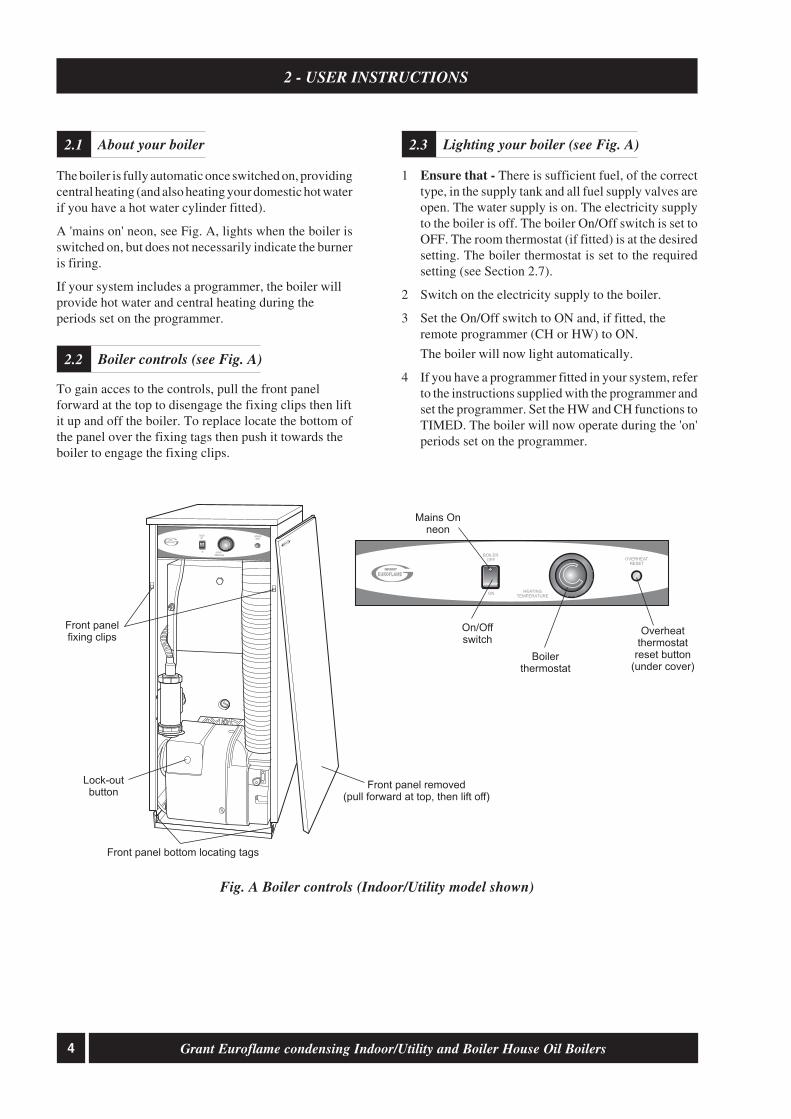
The boiler is fully automatic once switched on, providingcentral heating (and also heating your domestic hot waterif you have a hot water cylinder fitted).
A 'mains on' neon, see Fig. A, lights when the boiler isswitched on, but does not necessarily indicate the burneris firing.
If your system includes a programmer, the boiler willprovide hot water and central heating during theperiods set on the programmer.
To gain acces to the controls, pull the front panelforward at the top to disengage the fixing clips then liftit up and off the boiler. To replace locate the bottom ofthe panel over the fixing tags then push it towards theboiler to engage the fixing clips.
Fig. A Boiler controls (Indoor/Utility model shown)
About your boiler2.1
Boiler controls (see Fig. A)2.2
1 Ensure that - There is sufficient fuel, of the correcttype, in the supply tank and all fuel supply valves areopen. The water supply is on. The electricity supplyto the boiler is off. The boiler On/Off switch is set toOFF. The room thermostat (if fitted) is at the desiredsetting. The boiler thermostat is set to the requiredsetting (see Section 2.7).
2 Switch on the electricity supply to the boiler.
3 Set the On/Off switch to ON and, if fitted, theremote programmer (CH or HW) to ON.
The boiler will now light automatically.
4 If you have a programmer fitted in your system, referto the instructions supplied with the programmer andset the programmer. Set the HW and CH functions toTIMED. The boiler will now operate during the 'on'periods set on the programmer.
Lighting your boiler (see Fig. A)2.3
Boilerthermostat
Overheatthermostat
reset button(under cover)
On/Offswitch
OVERHEATRESET
HEATINGTEMPERATURE
OVERHEATRESET
BOILEROFF
ON
HEATINGTEMPERATURE
ON
BOILEROFF
Lock-outbutton
Front panel removed(pull forward at top, then lift off)
Front panelfixing clips
Front panel bottom locating tags
GRANT
Mains Onneon
EUROFLAME
EUROFLAME

5Grant Euroflame condensing Indoor/Utility and Boiler House Oil Boilers
For short periods - Set the On/Off to OFF.To restart, simply set the switch to ON.
For long periods: Set the On/Off switch to OFF andswitch off the electricity supply to the boiler. Ifrequired, the fuel supply valve may be closed and thewater and electricity supplies turned off at the mains.
To restart, refer to the full lighting instructions givenin Section 2.3.
1 Check that the boiler On/Off switch is ON.
2 Check that the programmer (if fitted) is workingand is in an 'on' period.
3 Check that all thermostats are set to the desiredsetting and are calling for heat.
4 Check if the burner 'Lock-out' reset button (on theburner) is lit. If it is, press it to start the burner. Ifthe burner fails to light and goes to 'Lock-out'again, check that you have sufficient fuel in thestorage tank and that the fuel supply valve is open.Check that the fire valve in the oil supply line has nottripped
5 Ensure that a fuse has not blown or that theelectricity supply has not failed.
6 Check to see if the safety thermostat has operated(see Section 2.7).
If the burner still fails to light after carrying out thesechecks then a fault exists. Switch off the electricitysupply to the boiler and contact your Service engineer.
Grant Euroflame condensing boilers only operate onClass C2 Kerosene to BS 2869:1998.
You should always quote this type of fuel when orderingfrom your supplier.
Do not wait until the fuel runs out before you ordersome more. Sludge in the bottom of the tank may bedrawn into the fuel lines. If it is possible, switch off theboiler when the new supply is delivered and leave thefuel to settle for an hour before restarting the boiler.
2 - USER INSTRUCTIONS
1 Boiler thermostat - This control allows thetemperature of the water leaving the boiler to heatthe radiators and domestic hot water to be adjusted.
Note: If you have a cylinder thermostat on your hotwater cylinder, this will control the temperature ofyour domestic hot water. The boiler thermostatsetting must be equal to or above the cylinderthermostat setting to enable the cylinder thermostatto control the domestic hot water system.
2 Burner Lock-out reset button - If there is aburner malfunction, a built-in safety circuitswitches the burner off and the 'Lock-out' resetbutton (on the burner) will light. Usually suchmalfunctions are short lived and pressing the resetbutton will restore normal operation.
If the burner continually goes to 'Lock-out' a faultexists or the fuel supply is low. If you have sufficientfuel, you will need to call your Service engineer.
3 Safety thermostat - Your boiler is fitted with a safetyoverheat thermostat which will automatically switchoff the boiler in the case of a control malfunctioncausing overheating.
If your boiler goes off and you try to light it butnothing happens and the 'Lock-out' reset button on theburner is not lit, the overheat thermostat has probablyoperated. The boiler will not light until the thermostatis reset. To reset, unscrew the small plastic cap (seeFig. A), press the button then replace the cap.
If this condition continually repeats, contact yourService engineer.
4 Programmer (if fitted) - Refer to the instructionssupplied with the Programmer.
5 Ventilation - Always ensure that the boiler hasadequate ventilation. Any ventilation openingsprovided by the Installer must not be obstructed.Periodically check that they are clear.
Do not attempt to 'box in' the boiler or build acompartment around it before consulting yourInstaller.
Do not place any combustible material around oron the boiler or flue pipe.
6 Flue terminal - The flue terminal on the outsidewall must not be obstructed or damaged.
In severe conditions check that the terminal doesnot become blocked by snow.
Turning off your boiler (see Fig. A)2.4
Points to check if burner fails to light2.5
About your fuel2.6
General notes and care of your system2.7
6 Grant Euroflame condensing Indoor/Utility and Boiler House Oil Boilers
7 Frost protection - Your Installer may have fitted afrost thermostat. If not, and you are likely to beaway for a short time, leave the boiler on with theboiler thermostat set at a low setting. For longerperiods the boiler and system should be drained.Contact your Service engineer for draining andfilling the system.
8 Cleaning and servicing - Lightly wipe over thecase with a damp cloth and a little detergent. Donot use abrasive pads or cleaners.
You must have your boiler serviced at least once ayear to ensure safe and efficient operation. Contactyour Service engineer for further details.
9 Failure of electricity supply - If the electricitysupply fails, the boiler will not operate. It shouldrelight automatically when the supply is restored.
The boiler requires a 230/240 V ~ 50 Hz supply. Itmust be protected by a 5 Amp fuse.
Warning: This appliance must be earthed.
If your boiler is operating on a sealed heating system,the installer will have pressurised the system andshould have told you (or set it on the pressure gauge)the system pressure when cold (this is normallybetween 0.5 and 1.0 bar, which will increase slightlywhen hot). If the pressure (when cold) is below the setpressure mentioned above, you can re-pressurise thesystem. If the system requires frequent re-pressurising,ask your Installer or Service engineer to check theheating system for leaks and to check the expansionvessel air charge.
The boiler or system will be fitted with an automatic airvent to remove air from the system. Any air trapped in theradiators should be removed by venting the radiatorsusing the vent screw at the top of each radiator. Only venta radiator if the top is cool and the bottom is hot.Excessive venting will reduce the system pressure, soonly vent when necessary and check the system pressureas mentioned above. Re-pressurise the system if necessary.
2 - USER INSTRUCTIONS
The boiler or system may be fitted with a safety valveto release excess pressure from the system. If water orsteam is emitted from the end of the safety valvedischarge pipe, switch off the boiler and contact yourInstaller or Service engineer.
The expansion vessel air charge must be checkedannually. Failure to maintain an adequate aircharge in the vessel may invalidate the warranty.
To re-pressurise the system by adding water:
1 Only add water to the system when it is cold andthe boiler is off. Do not overfill.
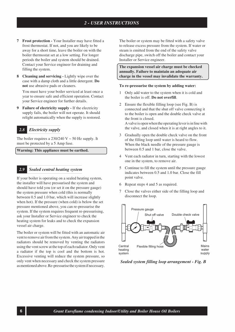
2 Ensure the flexible filling loop (see Fig. B) isconnected and that the shut off valve connecting itto the boiler is open and the double check valve atthe front is closed.A valve is open when the operating lever is in line withthe valve, and closed when it is at right angles to it.
3 Gradually open the double check valve on the frontof the filling loop until water is heard to flow.When the black needle of the pressure gauge isbetween 0.5 and 1 bar, close the valve.
4 Vent each radiator in turn, starting with the lowestone in the system, to remove air.
5 Continue to fill the system until the pressure gaugeindicates between 0.5 and 1.0 bar. Close the fillpoint valve.
6 Repeat steps 4 and 5 as required.
7 Close the valves either side of the filling loop anddisconnect the loop.
Electricity supply2.8
Sealed central heating system2.9
Sealed system filling loop arrangement - Fig. B
Centralheatingsystem
Mainswatersupply
Pressure gauge
Double check valveShut off valve
Flexible filling hose

7Grant Euroflame condensing Indoor/Utility and Boiler House Oil Boilers
22 mm (only connect plastic pipe)
100 mm
28.5 mbar
10 mbar
28 m
1m
65 to 75° C
111° C ± 3° C
Less than 50° C
230/240 V ~ 50 Hz Fused at 5 Amp
90
4.2
0.85
¼" BSP Male (on end of flexible fuel hose)
Minimum flue draught - 8.7 N/m² (0.035 in wg)
Maximum flue draught - 37 N/m² (0.15 in wg)
2.5 bar
2.5 bar
Boiler technical data3.1
3- BOILER TECHNICAL INFORMATION
Model
Water content litre
gal
* Weight (dry) kg
lb
Max. heat output kW
(kerosene) Btu/h
Flow connection
Return connection
Min. flow rate (∆T=10°C) l/h
Min. flow rate (∆T=20°C) l/h
Condensate connection
Flue diameter (conventional)
Waterside resistance
Flow/Return temp. diff. of 10°C
Flow/Return temp. diff. of 20°C
Maximum static head
Minimum circulating head
Boiler thermostat range
Limit (safety) stat shut off temp
Max. hearth temperature
Electricity supply
Motor power Watts
Starting current Amps
Running current Amps
Oil connection
Conventional flue
Max operating press - sealed sys
Max operating press - open sys
* Weight includes burner but excludes flue.
Euroflame condensing Indoor/Utility and Boiler House (BH)
90/120
19
4.2
121 (112 BH)
267 (247 BH)
34.7
118 400
22 mm (1" BSP BH)
22 mm (1" BSP BH)
2 980
1 490
50/70
13
2.9
103 (90.5 BH)
227 (200 BH)
20.7
70 600
22 mm (¾" BSP BH)
22 mm (¾" BSP BH)
1 780
890
70/90
13
2.9
103 (90.5 BH)
227 (200 BH)
25.6
87 350
22 mm (¾" BSP BH)
22 mm (¾" BSP BH)
2 200
1 100
8 Grant Euroflame condensing Indoor/Utility and Boiler House Oil Boilers
3 - BOILER TECHNICAL INFORMATION
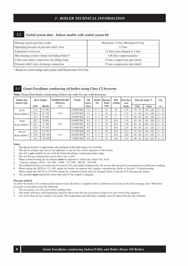
Note: Grant Euroflame condensing boilers are only for use with kerosene.
Grant Euroflame condensing oil boilers using Class C2 kerosene3.3
(kW)
15.1
18.1
20.7
20.7
22.7
25.6
25.6
30.8
34.7
(Btu/h)
51 500
61 750
70 600
70 600
77 500
87 350
87 350
105 100
118 400
Nozzle
0.50/80°EH
0.55/80°EH
0.60/80°EH
0.60/80°EH
0.65/80°EH
0.75/80°EH
0.75/80°EH
0.85/80°EH
1.00/80°EH
Oilpress.(bar)
7.0
7.5
8.5
8.5
8.5
8.0
8.0
9.1
8.0
SmokeNo.
0 - 1
0 - 1
0 - 1
0 - 1
0 - 1
0 - 1
0 - 1
0 - 1
0 - 1
Fuel flowrate
(kg/h)
1.29
1.53
1.78
1.78
1.95
2.19
2.19
2.65
2.93
Flue
70 - 75
75 - 80
80 - 85
85 - 90
85 - 90
90 - 95
75 - 80
85 - 90
90 - 95
CO2
(%)
11 - 12
11 - 12
11 - 12
11 - 12
11 - 12
11 - 12
11 - 12
11 - 12
11 - 12
Heat Output
50/70
Riello RDB2.2
70/90
Riello RDB2.2
90/120
Riello RDB2.2
Model andburner type
Sealed system data - Indoor models with sealed system kit3.2
Heating system pressure (cold)
Operating pressure of pressure relief valve
Expansion vessel size
Max heating system volume (including boiler)*
Cold water mains connection (for filling loop)
Pressure relief valve discharge connection
Maximum 1.0 bar, Minimum 0.5 bar
2.5 bar
12 litres (pre-charged at 1 bar)
128 litres (approximately)
15 mm compression (provided)
15 mm compression (provided)
* Based on vessel charge and system cold fill pressure of 0.5 bar
SEDBUK/HARPefficiency
(%)
93.0
92.4
92.1
B
C
C
N/A
N/A
N/A
N/A
N/A
N/A
Discsetting
*
*
*
Notes:1 The data given above is approximate only and based on the boiler using a low level flue.2 The above settings may have to be adjusted on site for the correct operation of the burner.3 Gas Oil is not suitable for use with the Grant Euroflame condensing boiler range.4 The net flue gas temperatures given above are ± 10%.5 When commissioning the air damper must be adjusted to obtain the correct CO
2 level.
6 * Factory settings: 50/70 - 18.1 kW, 70/90 - 22.7 kW, 90/120 - 30.8 kW.7 The combustion door test point may be used for CO
2 and smoke readings only. Do not use this test point for temperature or efficiency readings.
8 When setting the 50/70 to 15.1 kW output the burner air adjuster disc requires repositioning. Refer to Section 7 Commissioning.When setting the 90/120 to 25.6 kW output the combustion head must be changed. Refer to Section 9.4 Cleaning the burner.
9 The installer must amend the boiler data label if the output is changed.
Flue gas analysisTo allow the boiler to be commissioned and serviced, the boiler is supplied with a combustion test point on the front cleaning door. When thistest point is used please note the following:1. The test point is for CO
2 and smoke readings only.
2. The boiler efficiency and temperature must be taken from the flue test point on high level and vertical flue adaptors.3. Low level flues do not contain a test point. The temperature and efficiency readings must be taken from the flue terminal.
Burnerheadtype
T1
T1
T1
T1
T2
T2
T2
T3
T3
Flue gas temp °C
Door
155 - 160
175 - 180
185 - 190
195 - 200
205 - 210
215 - 220
190 - 195
215 - 220
220 - 225

9Grant Euroflame condensing Indoor/Utility and Boiler House Oil Boilers
3 - BOILER TECHNICAL INFORMATION
Fig. 1b - 90/120 Indoor/Utility dimensions
Fig. 1a - 50/70, 70/90 Indoor/Utility dimensions
Boiler dimensions3.4
61
82
170 61
86
LEFT SIDE VIEW
58
7
19
11560 25Flue centre line
RIGHT SIDE VIEW
PLAN VIEW
470
60
311
5
FRONT VIEW
470
441
250
90
0
69
6
205
Fluespigot
Alternativecondensatedrain outlets
624
17
REAR VIEW
430
200115
125
860
705
RIGHT SIDE VIEW
200
28
125
813
712
759
17
LEFT SIDE VIEW
110
605
Flue centre line
Flue centreline
Alternativecondensatedrain outlets
177
88
445
PLAN VIEW
430
605
110

10 Grant Euroflame condensing Indoor/Utility and Boiler House Oil Boilers
Fig. 1d - 90/120 Boiler House dimensions
Fig. 1c - 50/70, 70/90 Boiler House dimensions
3 - BOILER TECHNICAL INFORMATION
FRONT VIEW
431
714
600
595600
30
LEFT SIDEVIEW
Condensatedrain
RIGHT SIDEVIEW
PLAN VIEW
Return
327195
8835
Flow
FRONT VIEW
431
714
600
632690
30
LEFT SIDEVIEW
Condensatedrain
RIGHT SIDEVIEW
PLAN VIEW
Return
327195
8835
Flow

11Grant Euroflame condensing Indoor/Utility and Boiler House Oil Boilers
4 - GENERAL BOILER INFORMATION
Boiler description4.1
White system ...... High level and vertical concentricbalanced flue kit - components available:
Extensions 225 mm, 450 mm, 950 mm, adjustable275 to 450 mm and 45° elbowVertical concentric balanced flue kitExtensions 225 mm, 450 mm, 950 mm, adjustable275 to 450 mm and 45° elbow
All burners are pre-set for use with kerosene and aresupplied ready to connect to a single pipe fuel supplysystem with a loose flexible fuel line and 3/
8" to 1/
4" BSP
male adaptor supplied with the boiler.
If required, an additional flexible fuel line (600 mm) and3/
8" to 1/
4" BSP male adaptor are available to purchase
from your local stockist, for two-pipe oil supply systems.
The temperature of the water leaving the boiler to heatthe radiators and hot water cylinder is User adjustable.
The boiler is fitted with an overheat thermostat (whichallows it to be used on a sealed central heating system) whichwill automatically switch off the boiler if the heat exchangerexceeds a pre-set temperature of 111° C ± 3° C.
The control panel is fitted with an ON/OFF switch,boiler thermostat control knob and the manual resetbutton for the overheat thermostat.
Boiler components4.2
The Grant Euroflame range of automatic pressure jet oilboilers have been designed for use with a fully pumpedcentral heating system with indirect domestic hot watercylinder. They are not suitable for use with either a directcylinder or a 'primatic' cylinder or gravity hot water.
The boilers are suitable for use on open vented orsealed central heating systems. System models aresupplied with the necessary components factory fitted.See Section 4.13.
All models are supplied with the control panel andburner factory fitted.
The boilers can be connected to either a conventionalflue system or a balanced flue system, as required.
For Conventional flue applications where a chimney isto be lined - Grant recommends the use of the Grant‘Orange’ flue system, specifically designed for theGrant range of condensing boilers. Refer to Section4.7 for further details.
Important: The flue system materials and constructionMUST be suitable for use with oil-fired condensingboilers. Failure to fit a suitable conventional flue mayinvalidate the warranty on the boiler.
Fitting instructions for the Low level concentric, High leveland Vertical balanced flue kits are supplied with the kits.Where a balanced flue system is required, the followingflue kits are available from your local stockist.Refer to Section 4.8 for further details.
Yellow system ..... Standard low level concentricbalanced flue - components available:
Low level concentric balanced flue shortExtensions 225 mm, 450 mm and 675 mm90° extension elbow45° extension elbow45° elbow
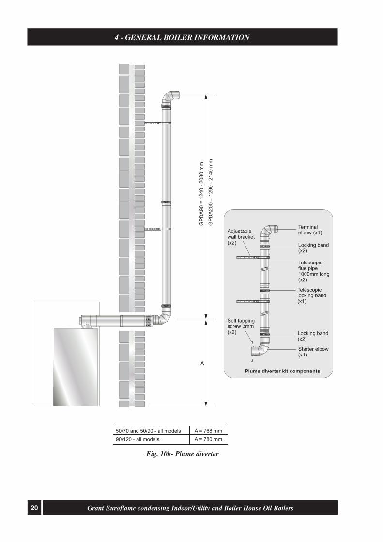
Where it is not possible to terminate the low level flueat low level, a plume diverter kit is available for fittingto the low level flue. The plume diverter kit diverts theflue gases up and terminates at a higher level. Whenfitting the plume diverter kit, follow the instructionssupplied with the kit. See Fig. 10b.
12 Grant Euroflame condensing Indoor/Utility and Boiler House Oil Boilers
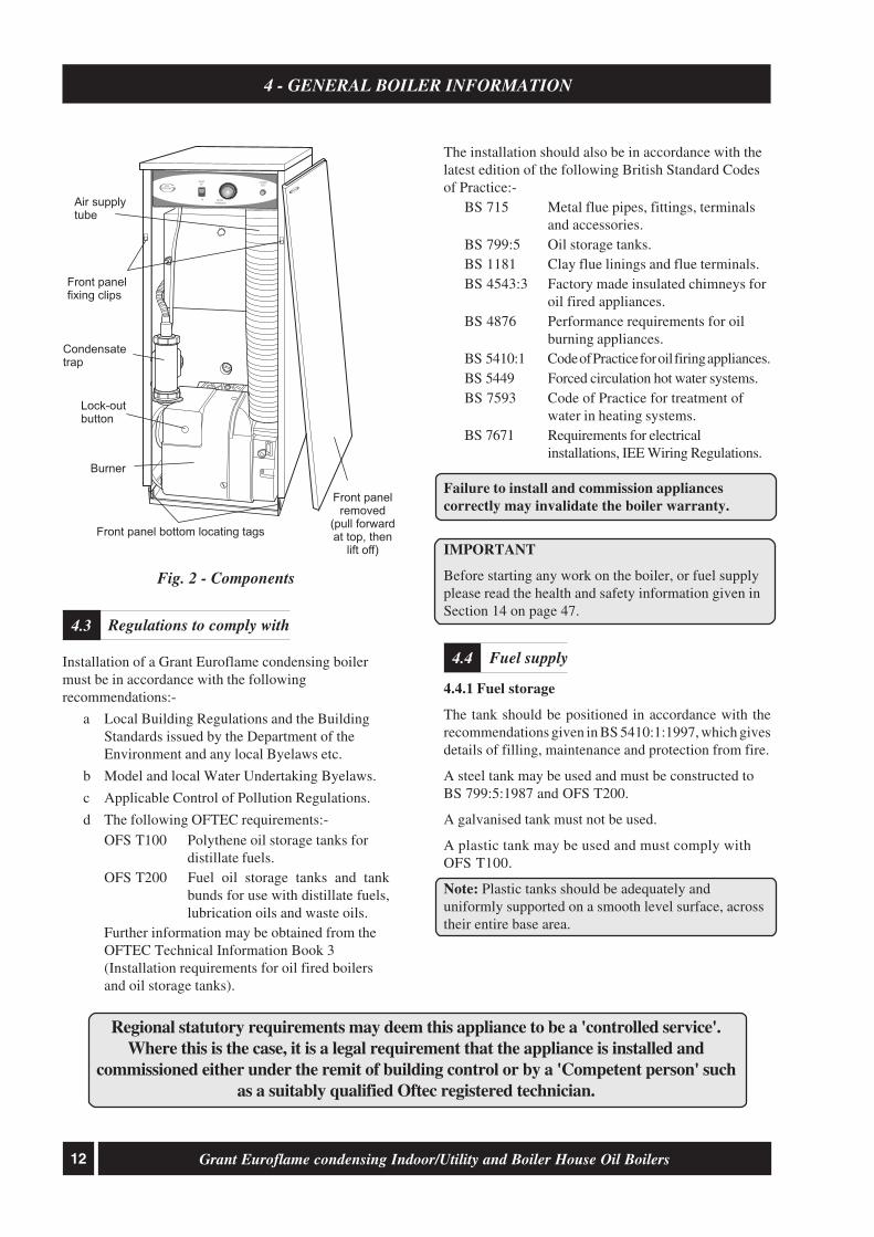
The installation should also be in accordance with thelatest edition of the following British Standard Codesof Practice:-
BS 715 Metal flue pipes, fittings, terminalsand accessories.
BS 799:5 Oil storage tanks.BS 1181 Clay flue linings and flue terminals.BS 4543:3 Factory made insulated chimneys for
oil fired appliances.BS 4876 Performance requirements for oil
burning appliances.BS 5410:1 Code of Practice for oil firing appliances.BS 5449 Forced circulation hot water systems.BS 7593 Code of Practice for treatment of
water in heating systems.BS 7671 Requirements for electrical
installations, IEE Wiring Regulations.
Failure to install and commission appliancescorrectly may invalidate the boiler warranty.
IMPORTANT
Before starting any work on the boiler, or fuel supplyplease read the health and safety information given inSection 14 on page 47.
4.4.1 Fuel storage
The tank should be positioned in accordance with therecommendations given in BS 5410:1:1997, which givesdetails of filling, maintenance and protection from fire.
A steel tank may be used and must be constructed toBS 799:5:1987 and OFS T200.
A galvanised tank must not be used.
A plastic tank may be used and must comply withOFS T100.
Note: Plastic tanks should be adequately anduniformly supported on a smooth level surface, acrosstheir entire base area.
Fuel supply4.4Installation of a Grant Euroflame condensing boilermust be in accordance with the followingrecommendations:-
a Local Building Regulations and the BuildingStandards issued by the Department of theEnvironment and any local Byelaws etc.
b Model and local Water Undertaking Byelaws.
c Applicable Control of Pollution Regulations.
d The following OFTEC requirements:-OFS T100 Polythene oil storage tanks for
distillate fuels.OFS T200 Fuel oil storage tanks and tank
bunds for use with distillate fuels,lubrication oils and waste oils.
Further information may be obtained from theOFTEC Technical Information Book 3(Installation requirements for oil fired boilersand oil storage tanks).
4 - GENERAL BOILER INFORMATION
Regulations to comply with4.3
Regional statutory requirements may deem this appliance to be a 'controlled service'.Where this is the case, it is a legal requirement that the appliance is installed and
commissioned either under the remit of building control or by a 'Competent person' suchas a suitably qualified Oftec registered technician.
Fig. 2 - Components
OVERHEATRESET
HEATINGTEMPERATURE
ON
BOILEROFF
Lock-outbutton
Front panelremoved
(pull forwardat top, then
lift off)
Front panelfixing clips
Condensatetrap
Front panel bottom locating tags
GRANT
Air supplytube
Burner
EUROFLAME

13Grant Euroflame condensing Indoor/Utility and Boiler House Oil Boilers
4 - GENERAL BOILER INFORMATION
4.4.2 Fuel pipes
1 Fuel supply pipes should be of copper tubing withan external diameter of at least 10 mm.Galvanised pipe must not be used.All pipe connections should preferably use flaredfittings. Soldered connections must not be used onoil pipes.
2 Flexible pipes must not be used outside the boiler case.
3 A remote sensing fire valve must be installed in thefuel supply line (outside) where it enters the building,with the sensing head located above the burner.Recommendations are given in BS 5410:1:1997.
4 A metal bowl type filter with a replaceable micronicfilter must be fitted in the fuel supply line adjacent tothe boiler. A shut-off valve should be fitted before thefilter, to allow the filter to be serviced.
5 A flexible fuel hose, adaptor and 1/4" BSP isolation
valve are supplied loose with the boiler for the finalconnection to the burner. If a two pipe system or'Tiger Loop' type de-aerator is used, an additionalflexible fuel hose (600 mm) and 3/
8" to 1/
4" BSP male
adaptor are available to purchase from your localstockist.
6 Metal braided flexible hoses should be replacedannually when the boiler is serviced. Long lifeflexible pipes should be inspected annually andreplaced at least every 60 months.
4.4.3 Single pipe system - (See Fig. 3)
1 Where the storage tank outlet is above the burnerthe single pipe system should be used. The heightof the tank above the burner limits the length ofpipe run from the tank to the burner.
2 As supplied the burner is suitable for a single pipesystem.
4.4.4 Two pipe system - (See Fig. 4)
1 When the storage tank outlet is below the burner,the two pipe system should be used. The pipe runsshould be as shown in Fig. 4. The return pipeshould be at the same level in the tank as thesupply pipe, both being 75 to 100 mm above thebase of the tank. The pipe ends should be asufficient distance apart so as to prevent anysediment disturbed by the return entering thesupply pipe.
2 Avoid the bottom of the tank being more than 3 mbelow the burner.
3 A non-return valve should be fitted in the supplypipe together with the filter and fire valve. A non-return valve should be fitted in the return pipe ifthe top of the tank is above the burner.
4 To be used with a two-pipe system, the burnermust be fitted with an additional flexible fuel hose(a flexible fuel hose (600 mm) and 3/
8" to 1/
4" BSP
male adaptor are available to purchase from yourlocal stockist. See Section 4.4.6.
5 The pump vacuum should not exceed 0.4 bar.Beyond this limit gas is released from the oil.
For guidance on installation of top outlet fuel tanks andsuction oil supply sizing, see OFTEC booklet T1/139.Available at www.oftec.org.uk.
Fig. 3 - Single pipe system
Filter
Firevalve
Shut-offvalve
Shut-offvalve
A
Sludgevalve
Fillpipe
VentpipeLevel
gauge
Fuelstoragetank
Firevalvesensor
Pump
Head A
(m)
Maximum pipe run (m)
0.5
1.0
1.5
2.0
10mm OD pipe
10
20
40
60
12mm OD pipe
20
40
80
100

14 Grant Euroflame condensing Indoor/Utility and Boiler House Oil Boilers
Fig. 5 - De-aeration device system
4.4.5 Tiger Loop system - (See Figs. 5 and 6)
1 When The storage tank is below the burner, an alternativeto a two pipe system can be achieved using a 'Tiger Loop'type oil de-aerator. This effectively removes the air fromthe oil supply on a single pipe lift.
2 The de-aerator is connected close to the boiler as atwo pipe system (omitting the non-return valve) asshown in Fig. 5. Refer to the manufacturersinstructions supplied with the de-aerator.The de-aerator must be mounted vertically andexternal.
4 - GENERAL BOILER INFORMATION
Fig. 4 - Two pipe system
Note: To prevent any possibility of fuel fumesentering the building, the de-aerator must be fittedoutside.
3 To be used with a de-aerator, the burner must befitted with an additional flexible fuel hose (aflexible fuel hose (600 mm) and 3/
8" to 1/
4" BSP
male adaptor are available to purchase from yourlocal stockist. See Section 4.4.6.
Filter
Firevalve
Shut-offvalve
Shut-off valve
Shut-offvalve
Seesection 4.4.6
A
Return
Supply
Head A
(m)
Maximum pipe run (m)
0
0.5
1.0
1.5
2.0
3.0
3.5
10mm OD pipe
35
30
25
20
15
8
6
12mm OD pipe
100
100
100
90
70
30
20
Nonreturnvalve
Firevalvesensor
Sludgevalve
Fillpipe
Ventpipe
Levelgauge
Fuelstoragetank
Firevalve
Tankmaster
Seesection 4.4.6
Sludgevalve
Fillpipe
Ventpipe
Fuelstoragetank
De-aeration devicee.g. Tiger Loop
See Fig. 6
Firevalvesensor
Return
Supply
15Grant Euroflame condensing Indoor/Utility and Boiler House Oil Boilers
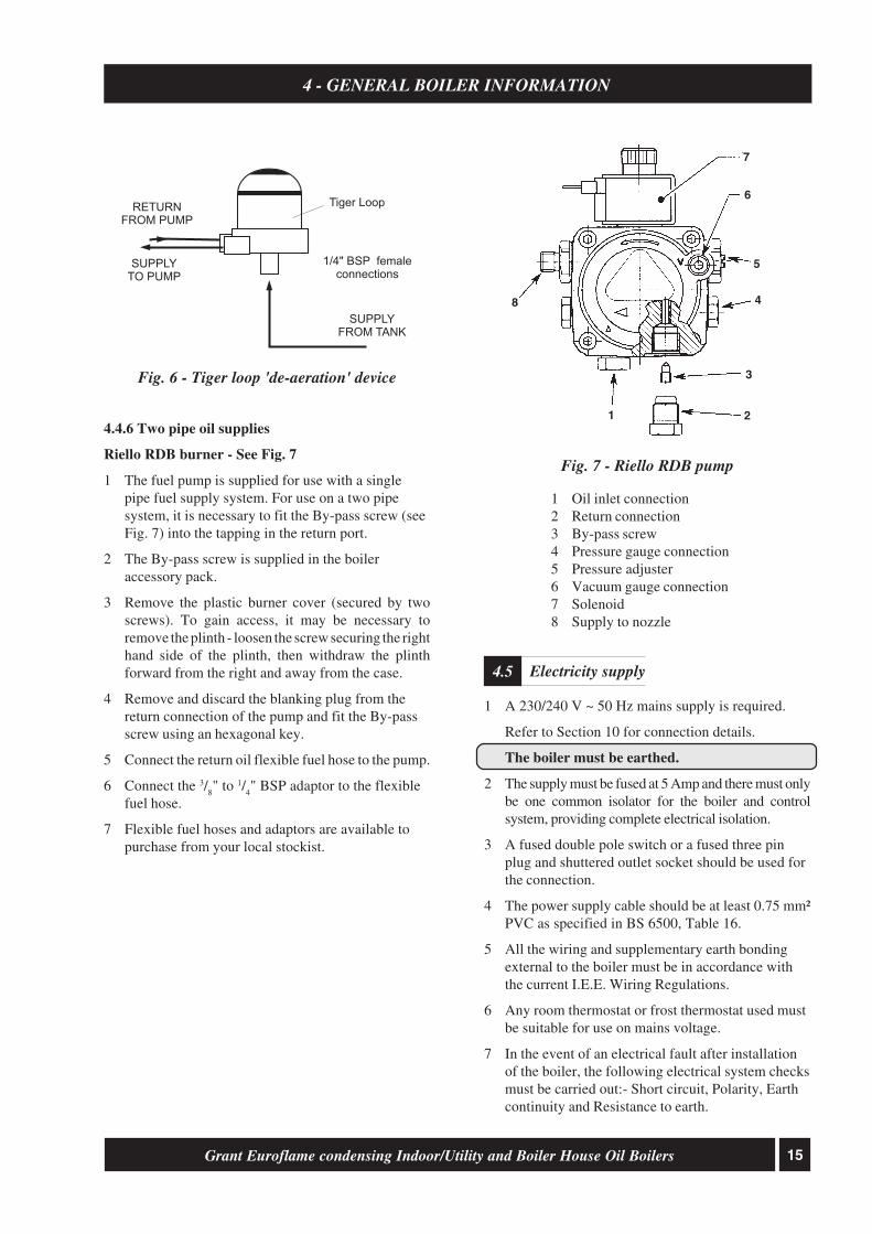
4.4.6 Two pipe oil supplies
Riello RDB burner - See Fig. 7
1 The fuel pump is supplied for use with a singlepipe fuel supply system. For use on a two pipesystem, it is necessary to fit the By-pass screw (seeFig. 7) into the tapping in the return port.
2 The By-pass screw is supplied in the boileraccessory pack.
3 Remove the plastic burner cover (secured by twoscrews). To gain access, it may be necessary toremove the plinth - loosen the screw securing the righthand side of the plinth, then withdraw the plinthforward from the right and away from the case.
4 Remove and discard the blanking plug from thereturn connection of the pump and fit the By-passscrew using an hexagonal key.
5 Connect the return oil flexible fuel hose to the pump.
6 Connect the 3/8" to 1/
4" BSP adaptor to the flexible
fuel hose.
7 Flexible fuel hoses and adaptors are available topurchase from your local stockist.
Fig. 6 - Tiger loop 'de-aeration' device
4 - GENERAL BOILER INFORMATION
Fig. 7 - Riello RDB pump
1 Oil inlet connection2 Return connection3 By-pass screw4 Pressure gauge connection5 Pressure adjuster6 Vacuum gauge connection7 Solenoid8 Supply to nozzle
1 A 230/240 V ~ 50 Hz mains supply is required.
Refer to Section 10 for connection details.
The boiler must be earthed.
2 The supply must be fused at 5 Amp and there must onlybe one common isolator for the boiler and controlsystem, providing complete electrical isolation.
3 A fused double pole switch or a fused three pinplug and shuttered outlet socket should be used forthe connection.
4 The power supply cable should be at least 0.75 mm²PVC as specified in BS 6500, Table 16.
5 All the wiring and supplementary earth bondingexternal to the boiler must be in accordance withthe current I.E.E. Wiring Regulations.
6 Any room thermostat or frost thermostat used mustbe suitable for use on mains voltage.
7 In the event of an electrical fault after installationof the boiler, the following electrical system checksmust be carried out:- Short circuit, Polarity, Earthcontinuity and Resistance to earth.
Electricity supply4.5
1/4" BSP femaleconnections
Tiger Loop
SUPPLYTO PUMP
RETURNFROM PUMP
SUPPLYFROM TANK
1 2
3
4
5
6
7
8

16 Grant Euroflame condensing Indoor/Utility and Boiler House Oil Boilers
BOILER IN
ROOM
Conventional open flue
C
BOILER IN
COMPARTMENT
Conventional open flue
compartment ventilated from room
Conventional open flue
compartment ventilated from outside
C C
D
D
E
BOILER IN
ROOM
Room sealed balanced flue
no ventilation required to room
BOILER IN
COMPARTMENT
Room sealed balanced flue
compartment ventilated from room
Room sealed balanced flue
compartment ventilated from outside
B
B
A
A
Fig. 8 - Air supply for room sealed balanced flue boilers
4 - GENERAL BOILER INFORMATION
Fig. 9 - Air supply for conventional flue boilers
50/70
116 cm² (18 in²)
232 cm² (36 in²)
90/120
198 cm² (31 in²)
396 cm² (62 in²)
Model
Vent A
Vent B
50/70
116 cm² (18 in²)
232 cm² (36 in²)
348 cm² (54 in²)
90/120
198 cm² (31 in²)
396 cm² (62 in²)
594 cm² (93 in²)
Model
Vent C
Vent D
Vent E
Air supply4.6
See Figs. 8 and 9
A sufficient permanent air supply to the boiler shouldbe provided:
a For proper combustion of fuel and effectivedischarge of combustion products to the open air.
b For the ventilation of any confined space inwhich the boiler is installed to preventoverheating of the boiler any equipment in andnear the boiler.
70/90
143 cm² (23 in²)
286 cm² (46 in²)
429 cm² (69 in²)
70/90
143 cm² (23 in²)
286 cm² (46 in²)

17Grant Euroflame condensing Indoor/Utility and Boiler House Oil Boilers
4 - GENERAL BOILER INFORMATION
It should be both the designer's and installer's concernthat the air required for these functions be introducedso as to cause as little discomfort as possible to thebuilding occupants and thus to offer them the leasttemptation to obstruct the ventilators.
Further details may be obtained from BS 5410:1:1997.
Notes:For a boiler fitted in a compartment, which isventilated as shown, no additional allowance isnecessary.Open flue - Extract fans, where needed, shouldbe in accordance with Section 4.4.7 in BS 5410Part 1 1997.All ventilation areas given are for domesticapplications. For all other cases refer to BS5410 Part 2 1978.
Under no circumstances can Grant condensingboilers be installed with existing flue systems. Onlyflue systems and components suitable for wet fluesshould be used.Failure to install the correct type of flue system willinvalidate the warranty.
See Fig. 10a and 10b
General
Grant condensing boilers have high operating efficienciesand low flue gas temperatures. Care must be taken toensure the flue system is suitable for the very low flue gastemperatures and condensate in the flue gases.
Suitable conventional flue systems (Orange system)are available from your local stockist - see Fig. 10a.
1 The flue must terminate in a down draught free area,i.e. at least 600 mm above the point of exit through theroof or preferably above the ridge level.
2 The condensate may be allowed to run back intothe boiler. A condensate drain at the base of theflue system is not required.
3 The flue terminal must be at least 600 mm fromany opening into the building, and 600 mm aboveany vertical structure or wall less than a horizontaldistance of 750 mm from the terminal. See Fig. 11.
4 If an existing chimney is to be used, it must be linedwith a smooth bore stainless steel liner suitable foruse with oil fired condensing boilers. The top andbottom of the annular space must be sealed.The internal flue and liner diameter for all modelsmust be 100 mm (4 in).
Conventional flue system4.7
Grant recommends the use of the Grant 'Orange'flue system, specifically designed for theEuroflame range of condensing boilers. Refer toSection 4.7 for further details.The maximum vertical height (from the top of theboiler to the terminal) for the 'Orange' system is19 metres.
Fig. 10a - Grant Orange flue system in a typicalbrick chimney
Brickchimney
Flaunching
Locking bandRigid to flexi flueconnector (bottom)
Thiscomponentmust be installedvertically
Note:
Extension
Boiler flueconnector
Boiler
Flexi pack
Terminal
Adjustable section 235/300mmWXA250/100WXA250/125
100mm dia.125mm dia.
Locking band
C
45 elbowO
Top plate
Clamp

18 Grant Euroflame condensing Indoor/Utility and Boiler House Oil Boilers
5 Twin-wall flues are recommended for externallyrun flues to reduce the possibility of the condensatefreezing in the flue.
6 No part of any flue system should be made of anasbestos material; aluminium must not be used inany part of the flue. Only stainless steel fluecomponents should be used.
7 If the draught conditions are satisfactory, the flueshould terminate with a standard cowl.
8 Refer to the locally applicable BuildingRegulations, BS 5410:1 and OFTEC InstallationRequirements (Books 2 and 3) for further guidanceon conventional flue systems.
It is important to ensure that the flue system is sealedand that condensate cannot escape. Up to 1.5 l/h ofcondensate can be produced in a conventional fluesystem.
Only use flue systems suitable for oil fired condensingboilers.
Do not use fire cement. The use of high temperaturesilicone sealants is recommended.
Grant EZ-Fit Flexi Pack conventional flue system(Orange System) - See Fig. 10a
A range of Flexi pack conventional flue lining kits areavailable from your local stockist. The packs have beenspecifically produced for Grant oil fired condensingboilers.
Contents of Grant EZ-Fit Flexi Pack
The pack includes a terminal/top plate/flexi flue adaptor,stainless steel smooth bore flexible flue liner, a rigid to flexiadaptor and a boiler flue connector.
4 - GENERAL BOILER INFORMATION
Extensions
A range of white powder coated single wall extensionsare available to connect the boiler to the flexible liner.The external diameter of the extensions is 100 mm.Extensions are supplied with locking bands.
Flue extensions cannot be cut.
Part No.
WX 150/100
WX 250/100
WX 450/100
WX 950/100
Extensions (Orange System)
100 mm dia. x 150 mm
100 mm dia. x 250 mm
100 mm dia. x 450 mm
100 mm dia. x 950 mm
Part No.
GFKIT 6/100
GFKIT 8/100
GFKIT 10/100
GFKIT 11/100
Flexi Pack (Orange System)
100 mm dia. x 6 metre
100 mm dia. x 8 metre
100 mm dia. x 10 metre
100 mm dia. x 11 metre
An adjustable extension and 45° elbow are alsoavailable. See Fig. 10a.
The rigid flue between the boiler and flexible flue linershould incorporate an adjustable section to allowinspection and cleaning of the flue system.

19Grant Euroflame condensing Indoor/Utility and Boiler House Oil Boilers
4 - GENERAL BOILER INFORMATION
Apart from a conventional flue, several balanced flueoptions are available for use with the Grant condensingboilers. All are suitable for use with Class C2 kerosene.
Note: None of the flue sections in the followingsystem can be cut.
1 Low level horizontal balanced flue (Yellow system)
Available in Standard kits.
Extensions are available which extend the flue by225 mm, 450 mm or 675 mm. 90° and 45° elbowsare also available.
The maximum flue length - from the centre of theboiler flue outlet to the outer face of the wall - is 4metres (with or without elbows included). No morethan 2 x 45° or 1 x 90° elbow should be fitted persystem.
2 High level (horizontal) balanced flue (Whitesystem)
Allows the flue to rise vertically within the buildingbefore exiting through the wall horizontally.
The maximum flue length - from the top of theboiler flue outlet to the outer face of the wall - is 10metres for all Euroflame condensing boilers.
Extensions are available which extend the flue by225 mm, 450 mm or 950 mm. An adjustableextension of 275 to 450 mm is also available.
A 45° elbow is also available. No more than 6 x 45°elbows should be fitted per system. Each elbow reducesthe overall maximum length of the system by 1 metre.
3 Vertical balanced flue (White system)
Allows the flue to rise vertically from the boiler toexit through the roof.
The maximum flue length - from the top of theboiler flue outlet to the terminal - is 12 metres forall Euroflame condensing boilers.
Extensions are available which extend the flue by225 mm, 450 mm or 950 mm. An adjustableextension of 275 to 450 mm is also available.
A 45° elbow is also available. No more than 6 x45° elbows should be fitted per system. Each elbowreduces the overall maximum length of the systemby 1 metre.
Balanced flue options4.8
Where it is not possible to terminate the low level flueat low level, a plume diverter kit is available for fittingto the low level flue. The plume diverter kit diverts theflue gases up and terminates at a higher level. Whenfitting the plume diverter kit, follow the instructionssupplied with the kit. See Fig. 10b.
The minimum dimensions for locating the terminalfrom building features (windows, doors, etc.) areshown in Fig. 11.
If the flue terminal is fitted less than 2 metres above asurface to which people have access, the terminal mustbe protected by a guard. The guard must be fittedcentrally over the flue terminal and securely fixed tothe wall.
The low level balanced flue (Yellow system) issupplied with a stainless steel guard. This must befitted in all circumstances to prevent objects fromentering the flue outlet.
The terminal must be positioned so as to avoidproducts of combustion accumulating in stagnantpockets around the buildings or entering intobuildings. Care should be taken that the plume fromcondensed flue gases does not cause a nuisance.
20 Grant Euroflame condensing Indoor/Utility and Boiler House Oil Boilers
4 - GENERAL BOILER INFORMATION
Fig. 10b- Plume diverter
GP
DA
90 =
1240 -
2080 m
m
GP
DA
200 =
1290 -
2140 m
m
Self tappingscrew 3mm(x2)
Locking band(x2)
Telescopiclocking band(x1)
Locking band(x2)
Adjustablewall bracket(x2)
Terminalelbow (x1)
Telescopicflue pipe1000mm long(x2)
Starter elbow(x1)
Plume diverter kit components
50/70 and 50/90 - all models
90/120 - all models
A = 768 mm
A = 780 mm
A

21Grant Euroflame condensing Indoor/Utility and Boiler House Oil Boilers
Frost protection4.9
4 - GENERAL BOILER INFORMATION
Fig. 11 - Clearances for Balanced flues
Notes: * 75 mm with protection.
** Only applies if one or both terminals are balanced flues.
Distances measured to rim of terminal.
Clearances recommended by Grant Engineering(IRL) Limited in accordance with BuildingStandards and Building Regulations.
A Below a gutter or sanitary pipework
B Horizontal from an opening, air brick or window
C Above ground or balcony level
D Below eaves or balcony
E From an internal or external corner
F From a terminal facing the terminal
G From a surface facing the terminal
H Vertical from terminals on the same wall
I Horizontal from terminals on the same wall
J Below an opening, air brick, window etc.
K From vertical sanitary pipework
L Vertical flue from a wallM From an oil storage tank
Min. distance (mm)Terminal position* 600
600
300
*600
300
1200
600
1500
**750
600
300750
1800
Notes:1 An opening means an openableelement, such as an openablewindow, or a permanent openingsuch as a permanently open air vent.
2 Notwithstanding the dimensionsgiven, a terminal should be at least300 mm from combustible material,e.g. a window frame.
3 A way of providing protection ofcombustible material would be to fita heat shield at least 750 mm wide.
Where the frost thermostat is installed outside the house (toprotect a boiler installed in an external boiler room orgarage) or in an attic, it is recommended that it be used inconjunction with a pipe thermostat to avoid unnecessary andwasteful overheating of the property. The pipe thermostatshould be located on the boiler return pipe, and set to operateat 25° C. Refer to Section 10 for connection details.
For additional protection of either the entire heatingsystem, or the boiler and localised pipework, it isrecommended that a frost thermostat be installed.Refer to Section 10 for connection details.To protect the heating system, the frost thermostatshould be sited within the house in such a place that itcan detect any rise and fall in the ambient airtemperature, i.e. in a room with a radiator.
The Installer must ensure that the terminal does not causea nuisance.

22 Grant Euroflame condensing Indoor/Utility and Boiler House Oil Boilers
4 - GENERAL BOILER INFORMATION
Boiler location4.10
1 The boiler must stand on a surface that is firm andlevel. It does not require a special hearth as thetemperature of the boiler base is less than 50° C.
2 Sufficient clearance must be allowed at the front of theboiler to remove the burner and baffles for servicing.
3 Once the boiler has been installed, a permanentworktop may be fitted over it as access to the topof the boiler is no longer required after installation.
Sealed system kit fitted - A removable section ofworktop above the boiler is required to provideaccess for servicing.
Water connections - all models See Fig. 124.11
IMPORTANT: Ensure that the flow pipe is vented at its highest point in the system.
All models
To avoid the danger of dirt and foreign matter entering the boiler the complete heating system should be thoroughlyflushed out - before the boiler is connected and then again after the system has been heated and is still hot. This isespecially important where the boiler is used on an old system.
For optimum performance after installation, this boiler and its associated central heating system must be flushed in accordance with theguidelines given in BS 7593:1992 'Treatment of water in domestic hot water central heating systems'.
For Long term protection against corrosion and scale, after flushing, it is recommended that an inhibitor such asBetzdearborn's Sentinel X100 or Fernox MB-1 is dosed in accordance with the guidelines given in BS 7593:1992.
Failure to implement the guidelines will invalidate the warranty.
A drain cock is fitted at the bottom on the front of the boiler to allow the heating system to be drained
50/70, 70/90, 90/120 Indoor/Utility
50/70, 70/90 Boiler House
90/120 Boiler House
22 mm pipe
¾" BSP
1" BSP
Compression
-
-
In fittings kit
Fitted
Fitted
22 mm pipe
¾" BSP
1" BSP
Compression
-
-
Fitted
Fitted
Fitted
Size SizeFitting FittingSupplied Supplied
Boiler model Flow connection Return connection

23Grant Euroflame condensing Indoor/Utility and Boiler House Oil Boilers
4 - GENERAL BOILER INFORMATION
See Fig. 13
Grant sealed system kits, incorporating circulatingpumps are available. See Section 6.6 and 6.7.
1 The boiler is only suitable for use with a sealed systemcomplying with the requirements of BS 5449.The maximum temperature of the central heatingwater is 75°C.
2 The system must be provided with the followingitems:-a Diaphragm expansion vessel complying with
BS 4814.b Pressure gauge.c Safety valve.d Approved method for filling the system.Refer to BS 7074:1 for further guidance.
Fig. 12 - Water connections and thermostat phial positions
Sealed system kit4.12
3 The expansion vessel can be fitted in either thereturn or flow pipework in any of therecommended positions as shown in Fig. 12. Toreduce the operating temperature of the expansionvessel diaphragm, position it below the pipe towhich it is connected. The expansion vessel may bepositioned away from the system, providing theconnecting pipe is not less than 13 mm diameter.
4 The pressure gauge should have an operating rangeof 0 to 4 bar.
5 The safety valve, set to operate at 2.5 bar, shouldbe fitted in the flow pipework near to the boiler.The pipework between the safety valve and boilermust be unrestricted, i.e. no valves. The safetyvalve should be connected to a discharge pipewhich will allow the discharge to be seen, butcannot cause injury to persons or property.
Euroflame condensing 50/70 and 70/90 Indoor/Utility
Heating flow
Heating return
Thermostat phials
Heating return
Heating flow
Euroflame condensing 90/120 Indoor/Utility
Thermostat phials
Euroflame condensing 50/70, 70/90 and 90/120 Boiler House
Dual stat phials
Heating return
Dual stat
Heating flow(under blanking plate)

24 Grant Euroflame condensing Indoor/Utility and Boiler House Oil Boilers
4 - GENERAL BOILER INFORMATION
Fig. 13 - Sealed system
6 Provision should be made to replace water lostfrom the system. This can be done manually (whereallowed by the local water undertaking) using anapproved filling loop arrangement incorporating adouble check valve assembly.
7 An automatic air vent should be fitted to thehighest point of the system, as the air vent in theboiler is for venting the boiler only.
8 The system design pressure (cold) should be between0.5 and 1.0 bar. This pressure is equivalent to themaximum static head in bar + 0.3 (1 bar = 10.2 metresof water).
9 All fittings used in the system must be able towithstand pressures up to 3 bar.
10 Radiator valves must comply with the requirementsof BS 2767(10):1972.
11 One or more drain taps (to BS 2879) must be usedto allow the system to be completely drained.
12 For proprietary expansion vessel/valve/gaugepacks, refer to the manufacturers instructions forthe correct location on the heating system.
1 A 15 mm discharge pipe must be connected to thesafety valve outlet connection. The pipework betweenthe safety valve and the boiler must be unrestricted,i.e. no valves. The discharge pipe should be run to theoutside of the building and terminate so that it cannotcause injury to persons or property.
2 A 15 mm double check valve ballofix type valve isprovided on the flexible filling loop hose forconnection of the cold mains supply to the heatingsystem. The cold mains supply should terminateinside the boiler casing.
3 The expansion vessel is connected via a flexiblehose to allow it to be moved to gain access to thebaffle cleaning cover. When replacing the vessel,care should be taken to ensure that the flexibleconnecting hose is not twisted.
On underfloor systems it is essential that the returntemperature must be maintained above 40° C toprevent internal corrosion of the boiler water jacket.
General - Grant boilers are compatible with bothcopper and plastic pipe. Where plastic pipe is used itmust be of the oxygen barrier type and be of thecorrect class (to BS 7291:Part 1:1990) for theapplication concerned.
IMPORTANT: The first metre of pipeworkconnected to both the heating flow and returnconnections of the boiler must be made in copper onall types of system - sealed or open-vented.
Sealed systems - If plastic pipe is to be used, theinstaller must check with the plastic pipe manufacturerthat the pipe to be used is suitable for the temperatureand pressures concerned. Pipe must be Class S to BS7291: Part 1:1990.
Water connections - Sealed system kit4.13
Pipework materials4.15
Underfloor heating systems4.14

25Grant Euroflame condensing Indoor/Utility and Boiler House Oil Boilers
4 - GENERAL BOILER INFORMATION
When in condensing mode the Grant Euroflamecondensing boilers produce condensate from the watervapour in the flue gases. This condensate is slightlyacidic with a ph value of around 3 (similar to vinegar).Provision must be made for the safe and effectivedisposal of this condensate.
Condensate can be disposed of using one of thefollowing methods of connection:
Internal connection (preferred option)
• into an internal domestic waste system (fromkitchen sink, washing machine, etc.)
• directly into the soil stack
External connection
• into an external soil stack• into an external drain or gulley• into a rainwater hopper (that is part of a combined
system where sewer carries both rainwater and foulwater)
• purpose made soakaway
All condensate disposal pipes MUST be fitted with atrap - whether they are connected internally orexternally to a domestic waste system/soil stack or runexternally to a gulley, hopper or soakaway.
General requirements5.1
Connections into a rainwater hopper, external drain orgulley should be terminated inside the hopper/drain/gulley below the grid level but above the water level.
Condensate disposal pipes should not be connecteddirectly into rainwater downpipes or to waste/soilsystems connected to septic tanks.
Condensate should not be discharged into 'grey water'systems that re-use water used in the home (notincluding water from toilets).
It should be noted that connection of a condensate pipeto the drain may be subject to local Building Controlrequirements.
Condensate disposal pipework must be plastic (plasticwaste or overflow pipe is suitable).
IMPORTANT: Copper or steel pipe is NOT suitableand MUST NOT be used.
Condensate disposal pipes should have a minimum'nominal' diameter of 22 mm (¾") - e.g. use 21.5 mmOD polypropylene overflow pipe.
Condensate disposal pipes must be fitted with a fall(away from the boiler) of at least 2.5° (~45 mm fallper metre run).
Connections5.2
Pipework5.3
5 - CONDENSATE DISPOSAL
Underfloor systems - Plastic pipe may be used onUnderfloor systems where the plastic pipe is fittedafter the thermostatic mixing valve. Copper tube mustbe used for at least the first metre of flow and returnprimary pipework between the boiler and theunderfloor mixing/blending valves.

26 Grant Euroflame condensing Indoor/Utility and Boiler House Oil Boilers
Note: Where it is not possible for the pipe to falltowards the point of discharge - either internally into awaste system or externally to a gulley (e.g. for boilersinstalled in a basement), it will be necessary to use acondensate pump.
Condensate disposal pipes should be kept as short aspossible and the number of bends kept to a minimum.
Pipes should be adequately fixed to prevent sagging,i.e. at no more than 0.5 metre intervals.
External pipework
Ideally, external pipework, or pipework in unheatedareas, should be avoided. If unavoidable, externalpipework should be kept as short as possible (less than3 metres) and 32 mm waste pipe used to minimise therisk of ice blocking the pipe in freezing conditions.
The number of bends, fittings and joints on externalpipes should be kept to a minimum to reduce the riskof trapping condensate.
Note: For boiler installed in an unheated area such asan outhouse or garage, all condensate pipework shouldbe considered as an ‘external’.
5 - CONDENSATE DISPOSAL
To keep external pipework to a minimum, locate thesoakaway as close as possible to the boiler but ensureit is at least 1 metre from building foundations andaway from other services, e.g. gas, electricity, etc.
The condensate pipe may be run above or belowground level and can enter either the top or side of thesoakaway tube. Refer to Fig. 14.
Ensure that the drainage holes in the soakaway tubeface away from the building.
Backfill both the soakaway tube, and the hole aroundit, with 10 mm limestone chippings.
Only use a soakaway where the soil is porous anddrains easily. Do not use in clay soils or where thesoil is poorly drained.
WARNING: Any damage due to condensate backingup into the boiler due to a high water table, in the caseof a soakaway, or flooded drains when the condensatedisposal is via a gulley or soil stack, is not covered bythe Grant product warranty.
Condensate soakaway5.4
Fig. 14 - Purpose made condensate soakaway
Ground level
32 mm waste pipe external to the building
2.5 fallO
25 mm
300 mm
400 mmmin.
Two rows of 3 x 12 mmholes at 25 mm centresand 50 mm from the bottomof the tube. Holes facingaway from the property.
Cement seal
100 mmplastictube
Sealedend
Backfill with 10 mmlimestone chippings

27Grant Euroflame condensing Indoor/Utility and Boiler House Oil Boilers
5 - CONDENSATE DISPOSAL
Condensate trap5.5
If there is any discharge of condensate from the overflowoutlet, this could indicate a blockage (possibly due tofreezing). Turn off the boiler and investigate the cause. Ifnecessary contact your service engineer for assistance.
Care should be taken when siting the trap such that theoverflow outlet is readily visible and that anycondensate overflowing from the outlet cannot causeeither a hazard to persons or damage to surroundingproperty or equipment.
The condensate trap outlet is at an angle of 48° belowthe horizontal. This is to automatically give a 3° fall onany 'horizontal' runs of condensate disposal pipe. Referto Fig. 15.
The outlet of the trap will accept 21.5 mm to 23 mmOD Polypropylene overflow pipe for the condensatedischarge pipe.
This discharge pipe can exit through the left hand sideof the boiler through one of pre-cut 'knock-outs' in thecasing panel (see to Fig. 1). Push out the 'knock-out'from the required hole taking care not to distort theside panel.
The trap MUST be checked at regular intervals (e.g.on every annual service) and cleaned as necessary toensure that it is clear and able to operate.
Note: The bottom bowl is sealed to the trap body andcannot be removed.
Fig. 15 - Condensate trap )Indoor/Utility models)
Grant Euroflame condensing Indoor/Utility boilers aresupplied with a factory-fitted condensate trap to provide therequired 75 mm water seal in the condensate discharge pipefrom the boiler.The condensate trap for the Boiler House models issupplied loose in the burner box and needs to be fitted asshown in Fig. 15a.
This trap incorporates a float (which will create a sealwhen the trap is empty) and an overflow warningoutlet (fitted with a plastic sealing cap), See Fig. 15.
On Indoor/Utility models the trap is factory-fittedinside the boiler casing (mounted on the inside of theleft side panel) in an accessible position to allow forroutine maintenance.
Note: If required, this condensate trap may be re-locatedoutside the boiler casing. Refer to procedure given in'external condensate trap'. This procedure MUST becarried out before the boiler is installed.
A flexible hose connects the outlet of the condensingheat exchanger to the trap inlet. Ensure the straightconnector on the hose is fully pushed onto the 'top hat'inlet connector of the trap.
With the trap fitted inside the boiler casing, the sealingcap MUST be fitted. If the trap is re-located outsidethe boiler then the following applies:
If connecting the condensate discharge (either internallyor externally) into a waste system or soil stack - thesealing cap MUST be fitted in the trap outlet.
On external discharge systems to a hopper, gulley orsoakaway, the sealing cap should be removed from thetrap outlet.
Condensate disposal pipework5.6
Inspection and cleaning of trap5.7
Condensatetrap
Condensateoutlet todrain
Overflowwarningoutlet(with cap)
Condensatedrain pipefrom boiler
Fig. 15a - Condensate trap (Boiler House models)
Condensatedrain from boiler
Minimum 2° fall
Overflow warningoutlet (with cap)
Condensate trap
Condensateoutlet to drain
Wall bracket

28 Grant Euroflame condensing Indoor/Utility and Boiler House Oil Boilers
5 - CONDENSATE DISPOSAL
To inspect and clean the trap:
1 Disconnect flexible condensate hose from inletconnector.
2 Unscrew the inlet connection nut.
3 Remove the inlet connector and nut from trap.
4 Disconnect the condensate outlet pipe from the trap.
5 Remove trap from bracket.
6 Remove float from trap – clean if necessary.
7 Inspect inside of trap and clean as necessary.
8 Re-assemble trap, re-fit to boiler and re-connectflexible hose. Ensure that hose is fully pushed ontothe trap inlet connector.
IMPORTANT: Failure to regularly check and cleanthe condensate trap may result in damage to the boilerand will not be covered by the Product Warranty.
To re-locate the factory-fitted trap outside the Indoor/Utility boiler casing, use the following procedure:
Note: This procedure must be carried out before theboiler is installed.
1 Remove the top casing panel(s) from the boiler.
2 Unscrew and remove the screws securing the leftside panel to the rear casing panel and the topbracing bracket of the boiler.
3 Carefully separate the left side and rear panels justenough to gain access to the condensate outlet onthe left rear of the condensing heat exchanger (seeFig. 16).
4 Push out pre-cut 'knock-out' from the condensateoutlet hole in the rear of left side casing panel.
5 Remove the right angle end of the flexiblecondensate discharge hose from the outletconnection on the condensing heat exchanger.
6 From the front of boiler, remove the straightconnector end of the flexible hose from the top ofthe condensate trap.
7 Reverse the flexible hose and pass the straightconnector end through the new hole in the left handcasing panel. Push the straight connector firmly ontothe condensate outlet connection of the condensingheat exchanger - push on at least 20 mm.
8 Refit the left hand casing panel to the rear panelusing the reverse procedure, ensuring all fixingscrews are used.
9 Remove the trap from the mounting bracket.
10 Unscrew and remove the trap mounting bracketfrom the left side panel.
11 Fix the trap mounting bracket to the wall adjacentto the boiler in the required position.
Note: The top of the trap must be below thecondensate connection on the boiler.
12 Re-fit the trap to the mounting bracket.
The mounting bracket supplied with the trapMUST be used - the trap should NOT besupported by the condensate pipework only.
13 Connect the flexible condensate hose to the trap,pushing the right angle hose connector onto thetrap inlet connection.
IMPORTANT: The flexible hose must fallcontinuously from the outlet to the top of the trap.
14 Connect the condensate discharge pipe to the outletof the trap. See Section 5.6.
Fig. 16 - Remove the condensate trap
External condensate trap fitting5.8
Rear panel
Left handside panel

29Grant Euroflame condensing Indoor/Utility and Boiler House Oil Boilers
1 Carefully remove the packaging from the boilerand remove it from the transit pallet.
2 Pull the front panel forward at the top to disengagethe fixing clips then lift it up and off the boiler.Remove the literature packs.
3 Indoor/Utility models only - Lift off the case toppanel(s) and remove the water connecting fittings.
Unpack the boiler6.1 Low level balanced flue6.2
6 - BOILER INSTALLATION
See Fig. 17 and 17a
If the boiler is to be used with a low level balancedflue (Yellow system) make the hole in the wall for theflue as shown in Fig. 17.
Note: Dimension B given in Fig. 17a includes anextra 10 mm over the size of the terminal to provideclearance for fitting.
Fig. 17a - Low level balanced flue (Yellow System)
Fig. 17 - Low level balanced flue
Side wallRear wall
Note: This dimension is given withthe boiler pushed back againstthe rear wall. Any clearancesmust be added to it.
Hole to becut in wall
Boilercentre line
Outlineof boiler
Rear exit Side exit
C
C
A
A
B
50/70 and 70/90 All models
90/120 All models
C
768
780
Dimension (mm)Model
A dia
127
162
B
115
115
30 Grant Euroflame condensing Indoor/Utility and Boiler House Oil Boilers
6 - BOILER INSTALLATION
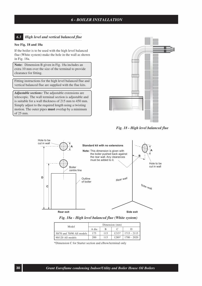
Fig. 18a - High level balanced flue (White system)
Fig. 18 - High level balanced flue
*Dimension C for Starter section and elbow/terminal only
High level and vertical balanced flue6.3
See Fig. 18 and 18a
If the boiler is to be used with the high level balancedflue (White system) make the hole in the wall as shownin Fig. 18a.
Note: Dimension B given in Fig. 18a includes anextra 10 mm over the size of the terminal to provideclearance for fitting.
Fitting instructions for the high level balanced flue andvertical balanced flue are supplied with the flue kits.
Adjustable sections: The adjustable extensions aretelescopic. The wall terminal section is adjustable andis suitable for a wall thickness of 215 mm to 450 mm.Simply adjust to the required length using a twistingmotion. The outer pipes must overlap by a minimumof 25 mm.
Side wall
Rear wall
Note: This dimension is given withthe boiler pushed back againstthe rear wall. Any clearancesmust be added to it.
Hole to becut in wall
Hole to becut in wall
Boilercentre line
Outlineof boiler
Rear exit Side exit
Standard kit with no extensions
D
C
A
A
B
50/70 and 70/90 All models
90/120 All models
D
1715 - 2115
1700 - 2020
Dimension (mm)Model
A dia
175
200
B
115
115
C
1215*
1280*

31Grant Euroflame condensing Indoor/Utility and Boiler House Oil Boilers
1. Lift off upper casing panel.
2. Remove the insulation from the underside of thepanel (do not discard it). Carefully press out thepre-cut flue opening in the top panel.
3. Remove the flue dress panel supplied in theliterature pack. Place the dress panel in position onthe rear casing top panel.
4. Re-fit the insulation to the panel with the foilsurface facing outwards. With a sharp knife cutaround the edge of the round opening in the dressplate to leave a round hole through the insulationfor the flue.
5. If the Grant ‘Orange’ flue system is being used –follow the instructions supplied with the flue kit.
6. Fully screw the length of threaded studding(provided in the kit) into the nut located in thecentre of the boiler flue outlet.
7. Fit the boiler connector (from the CF adaptor kit)over the threaded studding. Position flange on tothe neoprene gasket around the boiler flue outlet,ensuring that small spigot on the base of theconnector is located in the hole in the centre of theneoprene gasket and that end of studding passesthrough the hole in the of the spacer bracket. Fitwasher and wing nut provided onto end of threadedstudding and secure connector in position bytightening down on wing nut – as shown in Fig. 21.
8. Re-fit the rear top casing panel to the boiler –fitting it over the boiler connector.
9. Fit the flue adaptor (from the adaptor kit) into theboiler connector. Note lubricate the seal on theadaptor using the lubricant provided beforeattempting to fit the flue adaptor.
10. Fit the first section of flue into the flue adaptor andsecure using the clamp band provided.
11. Assemble the remainder of the flue system asrequired, lubricating the seal on each componentbefore fitting.
Make the water connections6.5
6 - BOILER INSTALLATION
Refer to Section 4.11 and 4.12 and Fig. 12. for the size,type and position of the connections.
The Flow and Return pipework can be routed to eitherside of the boiler, dependant on the type and directionof the flue system used.
For condensate disposal pipework refer to Section 5.
Pipe entry/exit holes in case
All models have holes to enable the pipework to exitthe boiler casing. On the 50/70 and 70/90 models theseholes are pre-cut knock-outs located at the rear of bothside panels and on the 90/120 model these pre-cutholes are in the removable flue outlet cover plates.Push out the 'knock-out' from the required holes,taking care not to distort the side panel.If access will be restricted, make any connections tothe boiler before placing it in its final position.If using a balanced flue system - Install the balanced fluesystem before connecting the heating system pipework tothe boiler. Once the flue system is fitted then complete thewater connections and fill the heating system.If using a conventional flue system - Complete thewater connections and fill the heating system.Check all connections for leaks and rectify as necessary.If the Grant sealed system kit is fitted, refer to Section 6.6 fordetails on filling and venting the sealed heating system.
Connect a conventional flue6.4
Fig. 19 - Boiler flue connector

32 Grant Euroflame condensing Indoor/Utility and Boiler House Oil Boilers
Sealed system kit - Indoor/Utility only6.6
6 - BOILER INSTALLATION
1 The kit includes the following items:Pressure relief valveAutomatic air ventManifold pipe22 mm push-fit elbow12-litre expansion vessel with flexible hose andsealing washerFilling loop kit - including pressure gauge mountedon shut-off valve6 m head circulating pump with 22 mm gate type valves15 mm copper pressure relief valve discharge pipe½" BSP black iron TeePump support bracket – with screw, nut & washer
2 Unscrew the burner securing nut and remove theburner from the boiler.
3 Remove the ½" BSP black iron plug from the front ofthe boiler waterway, using a 3/8" drive socket wrench.
4 Remove the compression nut and olive from theend of the filling loop shut-off valve. Fit the ½"BSP straight end of the shut-off valve into one sideof the black iron tee, using a suitable thread sealant(not supplied).
5 Fit the male thread of the black iron Tee into thetapping on the front of the waterway using a suitablethread sealant. Tighten until Tee (and shut-off valve)is horizontal and the valve is on the right hand side.
6 Connect the flexible expansion vessel hose to theremaining connection on the black iron Tee.
7 Position the 12-litre expansion vessel on the front ofthe boiler combustion door locating the vessel bracketinto cut-out in the front of the combustion door.Note: on 50/70 and 70/90 models press on the pre-cut section in the centre of the door to form the cut-out for the bracket.
8 Fit the ¾" BSP connection of the flexibleexpansion vessel hose to the vessel using the blackrubber washer supplied and tighten the nut.
9 Fit the pump support bracket to the vertical plateon top of the boiler shell. Fasten in place using thescrew, nut and washer provided.Note: On 90/120 model it will be necessary toremove existing nut and bolt. On the 50/70 and 70/90 models remove and discard the 'V' bracket fromthe top of the boiler.
10 Fit the 22 mm elbow onto the boiler flow connection.
11 Fit both the automatic air vent and pressure reliefvalve onto the manifold pipe.
12 Push the manifold pipe into the push-fit elbow so thatthe automatic air vent is to the front of the boiler.
13 Fit both 22 mm pump valves to the circulatingpump using the sealing washers supplied.
14 Fit the pump assembly to the automatic air vent/pressure relief valve assembly ensuring that thepump shaft is horizontal, the pump motor is facingtowards the front of the boiler and the body isresting on the pump support bracket. The flowarrow on the body of the pump must face in thedirection of flow away from the boiler connection.
15 Fit a 15 mm copper discharge pipe to the pressurerelief valve outlet using the nut and olive supplied.Note: The 15 mm discharge pipe supplied in thekit is not suitable for the Eco Utility model.
16 Re-fit the burner and tighten the fixing nut to secure.
17 The filling loop should be connected, via thedouble check valve, to a 15 mm cold water supplypipe from the mains at a convenient position insidethe boiler.
The expansion vessel fitted, is supplied with a chargepressure of 1.0 bar (equivalent to a max. static head of10.2 metres). The charge pressure must not be lessthan the actual static head at the point of connection.Do not pressurise the vessel above 1.5 bar.
The air pressure in the vessel must be checked annually.
The central heating system volume, using the expansionvessel as supplied, must not exceed the recommendedvolumes. If the system volume is greater, an extraexpansion vessel (complying with BS 4841) must befitted as close as possible to the central heating returnconnection on the boiler. The charge pressure of the extravessel must be the same as the vessel fitted in the boiler.Refer to BS 7074:1 for further guidance.
The air charge pressure may be checked using a tyrepressure gauge on the expansion vessel Schraedervalve. The vessel may be re-pressurised using asuitable pump. When checking the air pressure thewater in the heating system must be cold and thesystem pressure reduced to zero.
Sealed system expansion vessel pressure6.7

33Grant Euroflame condensing Indoor/Utility and Boiler House Oil Boilers
6 - BOILER INSTALLATION
1 Unpack the dual thermostat which comes suppliedin the burner box.
2 Undo the two screws fitted in the top panel (frontcentre).
3 Fit the dual thermostat complete with bracket usingthe screws supplied as shown in Fig. 12.
4 Remove the side blanking plate.
5 Fit the dual thermostat phials in the thermostatsaddle on the side of the boiler.
6 Replace the side blanking plate after commissioningis complete, ensuring that the phials are inserted fullyand are not pinched by the blanking plate.
7 Refer to Section 10 for wiring of the dual thermostat.
It is recommend that the boiler should be connected toa switched mains power supply from a programmer orcontrol system. A three core cable is required toconnect the boiler terminal block to the live supply.Refer to Section 10 for typical control system wiringdiagrams.
White cased models:
1 Lift off the boiler case top panel, if it has notalready been removed.
2 Remove the top of the control panel and open thecable clamp. Route the supply cable through thehole in the rear panel (using the grommet supplied)up to the control panel, pass it through the cableclamp and connect to the boiler terminal block(refer to Section 10) as follows:-
Brown to live (terminal 1)Blue to mains neutral (terminal 2)Green/Yellow to mains earth (terminal 3)
Note: Ensure that the route and length of the cableis such that the boiler front cover plate can beeasily removed without disconnecting the supplycable from the terminal block.
3 Secure the cable in the cable clamp.
4 Place the wiring cover in position over the terminalblock, taking care not to trap any wires and securein position with the M4 screws provided.
5 Ensure that all external wiring is adequately supported.
Do not switch on the electricity supply at this stage.
Boiler House models:
It is recommended that the boiler should be connectedto a switched mains power supply from an externaltimer or control system.
1 Check the thermostat phials are pushed fully intothe thermostat pocket on the side of the boiler.
2 Remove the overheat thermostat reset cap and undothe three screws securing the combined boiler/overheatthermostat cover and lift off the cover.
3 Withdraw the cable support bushes from the cover.Pass the burner supply cable through one of thebushes and connect it to the boiler (control)thermostat (refer to Fig. 23) as follows:-
Brown to terminal 1 of the control thermostat.Green/yellow and earth fly lead from the boilercasing to the earth terminal, marked on thecontrol thermostat.
4 Pass a switched mains power supply through the othercable support bush and connect it to the overheatthermostat as follows:-
Switched live (brown) to terminal C on theoverheat thermostat.Earth (green/yellow) and remaining earth fly leadfrom casing to the earth terminal, marked onthe overheat thermostat.The neutral (blue) wire from the burner supplymust be linked to the incoming neutral of theswitched mains supply using a single connector(not supplied).
Do not connect the neutral wires to either of thetwo thermostats.
5 Connect a link between terminal 2 on the overheatthermostat and terminal C on the control thermostat.
6 There is no connection to terminal 1 on theoverheat thermostat or terminal 2 on thecontrol thermostat.
7 Position the support bushes so as not to strain theconnections when the cover is replaced.
Place the cover in position locating the bushes atthe same time.
Note: It may be necessary to rotate the thermostatknob to engage it on the operating spindle as thecover is replaced.
8 Secure the cover in position by tightening the threescrews. Refit the overheat thermostat reset cap. Tightenthe cable support bush nuts to secure the cables.
9 Ensure all external wiring is adequately supported.
Do not switch on the electricity supply at this stage.
Connect the power supply6.9
Fit the dual thermostat - Boiler House6.8
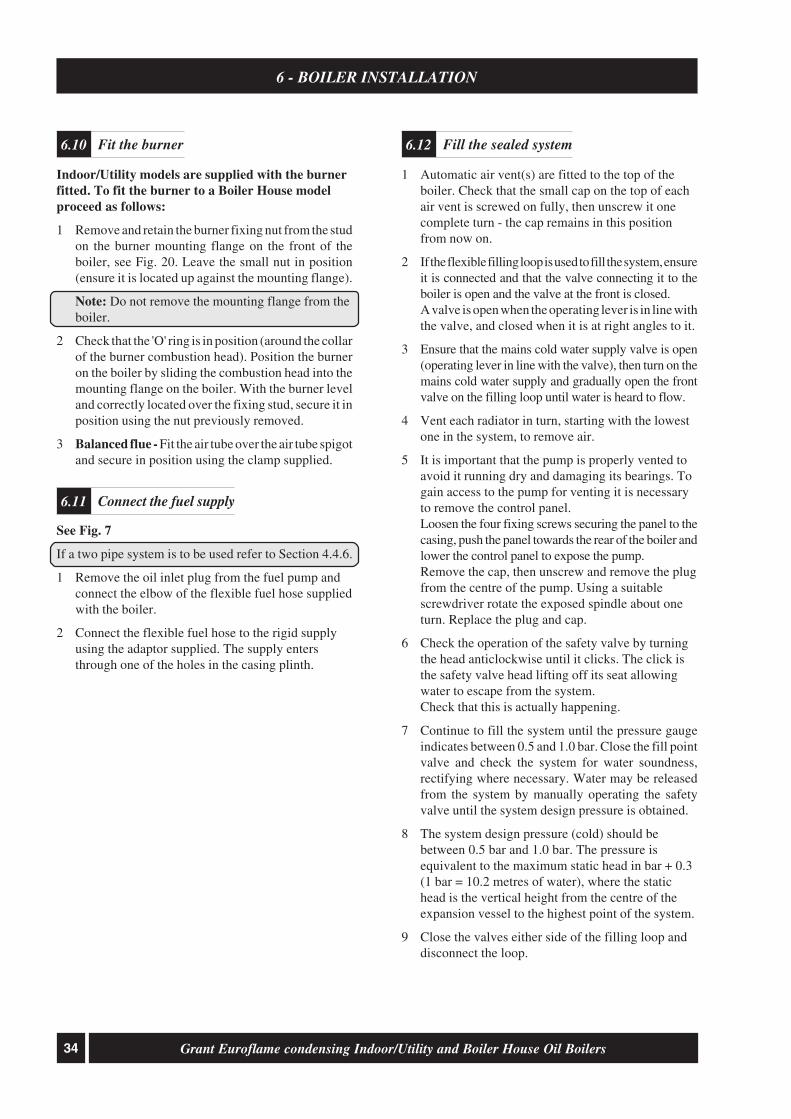
34 Grant Euroflame condensing Indoor/Utility and Boiler House Oil Boilers
6 - BOILER INSTALLATION
Indoor/Utility models are supplied with the burnerfitted. To fit the burner to a Boiler House modelproceed as follows:
1 Remove and retain the burner fixing nut from the studon the burner mounting flange on the front of theboiler, see Fig. 20. Leave the small nut in position(ensure it is located up against the mounting flange).
Note: Do not remove the mounting flange from theboiler.
2 Check that the 'O' ring is in position (around the collarof the burner combustion head). Position the burneron the boiler by sliding the combustion head into themounting flange on the boiler. With the burner leveland correctly located over the fixing stud, secure it inposition using the nut previously removed.
3 Balanced flue - Fit the air tube over the air tube spigotand secure in position using the clamp supplied.
See Fig. 7
If a two pipe system is to be used refer to Section 4.4.6.
1 Remove the oil inlet plug from the fuel pump andconnect the elbow of the flexible fuel hose suppliedwith the boiler.
2 Connect the flexible fuel hose to the rigid supplyusing the adaptor supplied. The supply entersthrough one of the holes in the casing plinth.
1 Automatic air vent(s) are fitted to the top of theboiler. Check that the small cap on the top of eachair vent is screwed on fully, then unscrew it onecomplete turn - the cap remains in this positionfrom now on.
2 If the flexible filling loop is used to fill the system, ensureit is connected and that the valve connecting it to theboiler is open and the valve at the front is closed.A valve is open when the operating lever is in line withthe valve, and closed when it is at right angles to it.
3 Ensure that the mains cold water supply valve is open(operating lever in line with the valve), then turn on themains cold water supply and gradually open the frontvalve on the filling loop until water is heard to flow.
4 Vent each radiator in turn, starting with the lowestone in the system, to remove air.
5 It is important that the pump is properly vented toavoid it running dry and damaging its bearings. Togain access to the pump for venting it is necessaryto remove the control panel.Loosen the four fixing screws securing the panel to thecasing, push the panel towards the rear of the boiler andlower the control panel to expose the pump.Remove the cap, then unscrew and remove the plugfrom the centre of the pump. Using a suitablescrewdriver rotate the exposed spindle about oneturn. Replace the plug and cap.
6 Check the operation of the safety valve by turningthe head anticlockwise until it clicks. The click isthe safety valve head lifting off its seat allowingwater to escape from the system.Check that this is actually happening.
7 Continue to fill the system until the pressure gaugeindicates between 0.5 and 1.0 bar. Close the fill pointvalve and check the system for water soundness,rectifying where necessary. Water may be releasedfrom the system by manually operating the safetyvalve until the system design pressure is obtained.
8 The system design pressure (cold) should bebetween 0.5 bar and 1.0 bar. The pressure isequivalent to the maximum static head in bar + 0.3(1 bar = 10.2 metres of water), where the statichead is the vertical height from the centre of theexpansion vessel to the highest point of the system.
9 Close the valves either side of the filling loop anddisconnect the loop.
Fit the burner6.10
Connect the fuel supply6.11
Fill the sealed system6.12

35Grant Euroflame condensing Indoor/Utility and Boiler House Oil Boilers
6 - BOILER INSTALLATION
Boilerthermostat
Overheatthermostat
reset button(under cover)
On/Offswitch
OVERHEATRESET
HEATINGTEMPERATURE
OVERHEATRESET
BOILEROFF
ON
HEATINGTEMPERATURE
ON
BOILEROFF
Lock-outbutton
Front panel removed(pull forward at top, then lift off)
Front panelfixing clips
Front panel bottom locating tags
GRANT
Mains Onneon
EUROFLAME
EUROFLAME
7 - COMMISSIONING
Boiler Passport - The Installer is responsible for completing the boiler passport supplied with this boiler andreturning the paperwork to Grant Engineering (IRL) Ltd.. This appliance must be correctly commissioned inaccordance with the appliance instructions and the details returned to Grant Engineering (IRL) Ltd. using the
address shown on the back of this manual.
Refer to Fig. 21 for boiler controls
1 Pump2 Control box3 Reset button with lock-out lamp4 Mounting flange with gasket (do not remove from boiler)5 Air damper adjustment screw
Fig. 20 - Riello RDB burner components
6 Air supply tube connection (balanced flue)7 Pump pressure adjustment screw8 Pressure gauge connection9 Burner fixing nut
Burner components6.13
7
8
1
23
5
4
699
Fig. 21 - (Indoor/Utility model shown)

36 Grant Euroflame condensing Indoor/Utility and Boiler House Oil Boilers
7 - COMMISSIONING
It is important that the following commissioningprocedure is carried out to ensure safe and efficientoperation of the boiler.
Note: Check that the baffles are in position and that therefractory base (insulation) is correctly located in thebase of the combustion chamber. Check that the cleaningcover is correctly fitted and a good seal made.
IMPORTANT:Check that the turbulators are in position and thatthe ends are vertical (see Fig. 25).
Notes: 1. If the 50/70 model is down rated to 15 kW,the burner air adjuster disc must also beadjusted to setting B as described overleaf.See Section 3.3.
2. If the 70/90 model is down rated to 21 kW,the burner head must also be changed to aT1 head. See Section 3.3.
1 Check that both the boiler overheat and boiler controlthermostat bulbs are correctly located in theirrespective pockets. For location of thermostat pockets,refer to Fig. 12. Also check the condition of boththermostat capillaries, i.e. that they are not damaged,broken or kinked, and that they are not trapped orcrushed between any internal boiler components.
2 Check that the water system has been vented (andpressurised if sealed system) and there are no leaks.
Ensure the flow pipe has been vented.
3 Check that all fuel line valves are open.
4 Remove the plastic burner cover if it was notpreviously removed.
5 Connect a combined vent manifold and pressuregauge to the pressure gauge connection port on the oilpump. See Fig. 7. Open the vent screw on your ventmanifold to vent the supply while the pump is running.
6 Set the On/Off switch to Off. Check that all systemcontrols are calling for heat and turn the boiler thermostatto maximum. Switch on the electricity supply.
7 Set the On/Off switch to On. The burner fan shouldstart and the burner should light within about 12seconds. If the burner does not light and the 'Lock-out' reset button lights, wait for about 45 secondsthen press the reset button to restart the ignitionprocess. This procedure may have to be repeatedseveral times during first lighting.
8 With the burner alight, check the fuel pressure. Referto the Technical Information, Section 3.3. Adjust thepressure if necessary - see Fig. 7. Note that the 'MainsOn' neon lights when the boiler is switched on, butdoes not necessarily indicate the burner is firing(Indoor/Utility models only).
9 Operate the boiler until it reaches normal operatingtemperature. Check oil supply/return pipe for leaks,rectifying where necessary.
10 Check the operation of the boiler thermostat. Ensure thatby turning it anticlockwise it switches the burner off.
11 With the burner alight, re-check the fuel pressure andre-adjust if necessary. Turn the boiler off, remove thepressure gauge and replace the plug in the pump.
12 Having ensured that there are no oil leaks, replace theburner cover. Ensure the flexible air tube is connectedto the burner (balanced flue models).
13 Relight the boiler and allow it to run for at least 20minutes.
14 Check the smoke number, if satisfactory check theCO
2. Set the CO
2 to the value given in Section 3.3
for the boiler concerned.Use the hexagonal key supplied to adjust theburner air damper (see Fig. 20) as required.Turning the screw anti-clockwise closes thedamper and increases CO
2 level, turning the screw
clockwise opens the damper and reduces CO2 level.
Re-check the smoke number if the damper has beenmoved. Under no circumstances must the smokenumber be above 1.
Note: It is important that the air damper iscorrectly set.
15 Check the flue gas temperature.
16 Replace the case top on the Indoor/Utility models orthe side blanking plate on the Boiler House models.
17 When the boiler has been adjusted and is runningsatisfactorily, balance the central heating system byadjusting the radiator lock shield valves. Start withthe radiator nearest the boiler and adjust the valvesto achieve the required temperature drop acrosseach radiator. If thermostatic radiator valves havebeen installed, check the system by-pass.
18 Switch off the boiler.
19 With the system hot, check again for leaks,rectifying where necessary. Drain the system whileit is hot to complete the flushing process. Refill andvent (and pressurise if a sealed system) the system.
20 A suitable central heating system inhibitor must beadded to protect the system against the effect of corrosion.
21 Indoor/Utility models - Replace the front panel. Locatethe bottom of the panel over the fixing tags then pushit towards the boiler to engage the fixing clips.
Note: After commissioning the boiler complete theboiler passport that comes supplied with this boilerand return the commissioning details to GrantEngineering (IRL) Ltd.

37Grant Euroflame condensing Indoor/Utility and Boiler House Oil Boilers
If the boiler is to be left in service with the User, set thesystem controls to the User's requirements.
If the boiler is not to be handed over immediately,close the boiler fuel supply valve and switch off theelectricity supply.
If there is any possibility of the boiler being left during frostconditions, then the boiler and system should be drained.
IMPORTANT NOTE:To allow the boiler to be commissioned and servicedcorrectly a combustion test point is provided on the frontcleaning door.The CO
2 and smoke test may all be carried out using this
test point. The test point is not suitable for measuringboiler efficiency or conventional flue draught.
When using the test point on the cleaning cover note that theflue gas temperature reading will be higher than that measuredin the flue thus resulting in an inaccurate efficiency reading.To obtain an accurate flue gas temperature and efficiency,the reading can only be measured outside through the lowlevel flue terminal. For high level and vertical balanced fluesthe reading may be taken from the flue kit test pointprovided. Refer to Section 3.3.
For Conventional flue draught measurement and efficiencya test point is provided in the conventional flue adaptor.
To adjust the 50/70 air adjuster disc whendownrating - See Fig. 22
1. Ensure the boiler is isolated from the electrical supply.
7 - COMMISSIONING
The User must be advised (and demonstrated ifnecessary) of the following important points:-
1 How to light and turn off the boiler and how tooperate the system controls.
2 The precautions necessary to prevent damage tothe central heating system and to the building, inthe event of the boiler not being in operationduring frost conditions.
3 The importance of servicing the boiler to ensuresafe and efficient operation. This should normallyonly be required once a year.
4 The type of fuel used.
5 That any servicing or replacement of parts mustonly be carried out by a suitably qualified engineer.
6 Ensure that the boiler controls and room thermostat(if fitted) are set to the User's requirements.
7 If the boiler is used on a sealed heating system, tellthe user the system pressure and show them theposition of the safety valve discharge pipe.
8 Show the User how to reset the overheat thermostatand how to restart the boiler if it goes to 'Lock-out'.
Leave this Instruction manual with the User.
To ensure your continued Boiler Warranty, the annualservice must be carried out by an OFTEC RegisteredTechnician or an otherwise competent person.
Use of non-competent persons may invalidate thiswarranty. A list of OFTEC Registered Technicians isavailable at www.oftec.org or alternatively telephoneOFTEC on 0845 658 5080 (UK) or 01 864 5771 (ROI).
If there is any doubt as to the suitability of yourtechnician, please check with the manufacturer prior tothe work being carried out.
2. Disconnect the air supply tube.
3. Remove the burner from the boiler.
4. Undo the two screws and remove the air inlet coverfrom the side of the burner.
5. The secondary air shutter disc is factory set in position‘C’ – i.e. with the cut-out marked C located againstthe die-cast boss on the fan housing - suitable foroutputs of 18.3 and 21 kW only. See Fig 22.
6. Remove the screw from the centre of the air shutterdisc, and re-position the disc such that the cut-out‘B’ (corresponding to 15 kW output setting – SeeSection 3.3) is located against the cast boss on thefan housing. Replace the screw in the centre of theair shutter disc and tighten.
7. Re-fit the air inlet cover to the side of the burnerand reassemble in reverse order.
Fig. 22 - 50/70 air adjuster disc at position 'C'
D
E
F
G
H
LM I
8 - INFORMATION FOR THE USER

38 Grant Euroflame condensing Indoor/Utility and Boiler House Oil Boilers
9 - BOILER SERVICING
To ensure efficient operation of the boiler it isrecommended that it is checked and serviced asnecessary at regular intervals. The frequency ofservicing will depend upon the particular installationconditions and usage, but in general once per yearshould be adequate.
Servicing and replacement of parts must only becarried out by a suitably qualified engineer.
Important: Details of every service should beentered in the boiler passport. This informationmay be required to validate the Grant extendedwarranty.
IMPORTANT
Before starting any work on the boiler, or fuel supplyplease read the health and safety information given inSection 14 on page 47.
1 Check the flue terminal and ensure it is not blockedor damaged.
2 Run the boiler and check the operation of its controls.
3 Ensure that all water/fuel system connections andfittings are sound. Remake any joints and check thetightness of any fittings that may be leaking.
If the boiler is used on a sealed central heatingsystem, check the system pressure, check theoperation of the pressure relief valve and check theexpansion vessel air charge. See Section 6.6.Refill, vent and re-pressurise the system asnecessary. See Section 6.11
4 Check that any ventilation openings are adequateand are clear. See Section 4.7.
5 Remove any sludge/water from the fuel tank byopening the sludge valve at the lower end of the tank.
6 With the fuel supply valve closed, clean/replace thefilter element and clean the filter bowl.
7 Flexible fuel supply hoses should be inspected annuallywhen the boiler is serviced and braided hoses replacedevery year. If in doubt replace the hoses
Warning: Before servicing, set the boiler On/Offswitch to Off, isolate the electricity supply and closethe fuel supply valve. Allow the boiler to cool.The data label on the inside of the case side panel willindicate the fuel used and the nozzle fitted.
1 Pull the front panel forward at the top to disengagethe fixing clips then lift it up and off the boiler.
2 If a sealed system kit is fitted, carefully lift up andremove the expansion vessel from the front of theboiler. Place the vessel on the floor taking care notto strain the flexible pipe.
3 Disconnect the flexible air tube from the burner.
4 Remove the burner fixing nut (top of mountingflange) and withdraw the burner.If required, disconnect the flexible oil hose(s), usea suitable container to prevent any oil spillage.
Note: If two flexible hoses are connected to theburner, identify (mark if necessary) which is theinlet and return if they are to be disconnected.
1 Remove the nuts and washers securing the frontcleaning door and withdraw the door. Take care - itis heavy.
2 Remove the baffles as shown in Fig. 23 or 24.
3 Remove all deposits from the baffle plates and allthe boiler internal surfaces using a stiff brush andscraper if necessary.
4 Check the condition of the flue, clean as necessary.
5 Check the condition of the front cleaning door seal,replace if necessary.
6 Replace the baffles, ensuring they are correctlyfitted. See Fig. 23 or 24.
7 Pull out the spiral turbulators from the heatexchanger tubes. See Fig. 25.Clean the turbulators using a stiff brushTest the heat exchanger condensate drain by pouringwater into one of the lower tubes and observe whetherthe water discharges from the 22 mm condensateoutlet. Replace the turbulators.
8 Replace the front cleaning door, ensuring the sealis in good condition and secure it in position withthe nuts and washers previously removed. Tightento form a seal.
9 Remove the condensate trap (refer to Section 5.7)and check that it is not blocked and is operatingcorrectly, i.e. the float is free to move. Clean thetrap and float as required.
Important notes prior to servicing9.1
Dismantling prior to servicing9.2
Cleaning the boiler9.3

39Grant Euroflame condensing Indoor/Utility and Boiler House Oil Boilers
9 - BOILER SERVICING
10 Check that the boiler condensate outlet isunobstructed. Clean if necessary.
IMPORTANT: The condensate trap and condensateoutlet must be checked on every service and cleaned asnecessary.
Fig. 23 - 50/70, 70/90 baffles
Fig. 24 - 90/120 baffles
RIGHTBAFFLES
LEFTBAFFLES

40 Grant Euroflame condensing Indoor/Utility and Boiler House Oil Boilers
9 - BOILER SERVICING
Cleaning the burner9.44 ± 0.3 mm
3 to 3.5 mm
Clamp screw
IMPORTANT: The electrode settings given aboveMUST be observed
See Section 12.1
1 Combustion head - Loosen the two screwssecuring the combustion head and withdraw thehead. Clean and refit the combustion head.
2 Inspect the ignition electrodes - Remove thecombustion head.
Loosen the electrode clamp screw and withdraw theelectrode assembly. Wipe clean and check for anycracks in the ceramic insulation. Replace if necessary.
Check the electrode settings
Electrode tips approximately 4 mm apart and 3 to3.5 mm in front of the nozzle, see Fig 26.
3 Nozzle - The nozzle should be replaced on anannual service - Check that the nozzle size and typeare correct, refer to table in Section 3.3 and boilerdata label.
With the combustion head removed, loosen theelectrode assembly clamp screw and slide theelectrodes away from the nozzle.
Do NOT attempt to clean the nozzle.
Remove the nozzle using a good fitting spanner(16 mm). The use of an ill-fitting spanner willdamage the nozzle and could lead to an incorrectflame pattern. Always check the electrodesettings after replacing the nozzle, see Fig. 26.
Turbulators
IMPORTANT:The ends of theturbulators mustbe vertical
Position in vertical plane
Fig. 25 - Turbulators (50/70, 70/90 shown)
Fig. 26
All models
1 Photocell - The photocell is a push-fit in the burnerbody. Carefully pull out the photocell to clean.
2 Burner fan - With the air intake grille or spigotremoved, remove the screws securing the fanhousing cover (R/H side of burner) and remove thecover. Inspect the fan and housing and clean asnecessary. Replace the cover.
3 Pump filter - With the burner cover removed, removethe four screws securing the pump end cover. Removethe filter and wash in kerosene. Replace the filter andend cover, ensure the 'O' ring is in position. Check forthe presence of sludge or water.
Re-assemble in reverse order.
To ensure safe and efficient operation of the boilerit is important that re-commissioning is carried out,especially combustion checks (CO
2 level, flue gas
temperature and smoke number) after the boilerhas been serviced.
Refer to the Commissioning instructions starting onpage 35.

41Grant Euroflame condensing Indoor/Utility and Boiler House Oil Boilers
Control panel wiring diagram - Indoor/Utility10.1
10 - WIRING DIAGRAM
Typical control system wiring diagram - Indoor/Utility10.2
Limit
ThermostatControl
Thermostat
2C1 C
1A 2A
ENL E N L
1 2 3 4 5 6
E
N
L
E
N
L
Supply to
Burner
Mains Supply:
Use 2 pole isolator
with power "ON"
indicator
G/Y
G/Y
G/Y
R
Bl
Bl
Br
Br Br
Colour code: Br - Brown, Bl - Blue, R - Red, G/Y - Green/Yellow
BoilerOn/Off
G/Y
4B 5B
G/Y
Bl
Br
G/Y
Bl
Br
Boiler Terminal Block
LNE
240 V50 HZ
LNE
Supply toBurner
FrostStat
Pipe Stat(if fitted)
1 3 4 N L
PumpE
NL
WiringCentre
1 2 3 4 5 6 7 8 9 10
Boiler Terminal BlockGrant 2-Channel Wall MountedProgrammer (Ref. ESKIT)
1 2 3 4 5 6
L N E E N L
CH and HW controlled by 3-port mid position valve
CylinderStat
1
C 2
RoomStat
2 1 3
3-PortMid PositionZone Valve
Blu
e
Gre
en
/Ye
llow
Wh
ite G
rey
Ora
ng
e
CH & HW controlled by two 2-port zone valves
CylinderStat
1 C
Room Stat
2 1 3
2-portZone Valve
MotorHTG
2-portZone Valve
MotorDHW
Grey
Blue Blue
Bro
wn
Bro
wn
Ora
ng
e
Gre
en
/Ye
llow
Green/Yellow Orange
Grey
FrostStat
Pipe Stat(if fitted)
1 3 4 N L
LNE
240 V50 HZ
PumpE
NL
WiringCentre
1 2 3 4 5 6 7 8 9 10
Boiler Terminal BlockGrant 2-Channel Wall MountedProgrammer (Ref. ESKIT)
1 2 3 4 5 6
L N E E N L
LNE
Supply toBurner
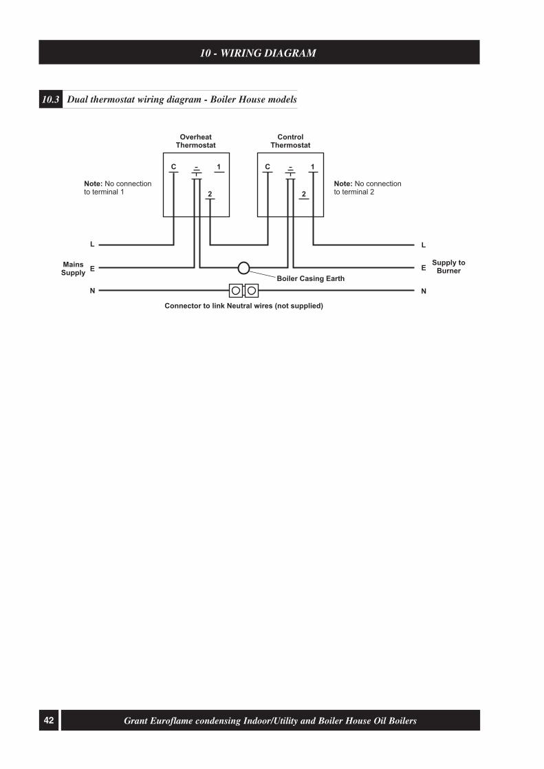
42 Grant Euroflame condensing Indoor/Utility and Boiler House Oil Boilers
10 - WIRING DIAGRAM
Dual thermostat wiring diagram - Boiler House models10.3
OverheatThermostat
Supply toBurner
MainsSupply
ControlThermostat
LL
EE
NN
Boiler Casing Earth
Connector to link Neutral wires (not supplied)
2
C 1
2
C 1
Note: No connectionto terminal 1
Note: No connectionto terminal 2

43Grant Euroflame condensing Indoor/Utility and Boiler House Oil Boilers
11 - FAULT FINDING
Burner fault finding11.1
Mo
tor/
pu
mp
se
ize
d
or
tig
ht
Re
pla
ce
mo
tor
ca
pa
cito
r
Bu
rne
r
mo
tor
run
s
Check
L&
N
tocontr
ol
box
Ch
eck
bo
iler
co
ntr
ols
Moto
rgiv
es
50
Volts
tow
hite
wire
*
Re
pla
ce
bu
rne
r
mo
tor
Re
pa
ir
or
rep
lace
mo
tor/
pu
mp
Lo
cko
ut
aft
er
12
se
c
pu
rge
Lo
cko
ut
with
in
1se
co
nd
Re
pla
ce
so
len
oid
co
il
Co
ilo
f
so
len
oid
so
un
d**
Re
pa
iro
r
rep
lace
oil
pu
mp
Wa
sh
ing
pre
ssu
re
1to
2b
ar
Ph
oto
ce
ll
so
un
d**
*
Ifb
ala
nce
dflu
e,
rem
ove
air
tub
e
an
dre
test
Re
se
al
ba
lan
ce
dflu
e
or
rep
ositio
nflu
e
Re
pla
ce
ph
oto
ce
ll
Drive
co
up
ling
bro
ke
n
Pu
mp
pro
du
ce
s
pre
ssu
re
Re
pla
ce
no
zzle
Conta
min
ate
d
fue
lo
r
filte
r
Co
mb
ustio
n
air
se
t
Fla
me
off
an
d
relig
hts
Bo
iler
or
flu
e
blo
cke
d
Co
mb
ustio
n
he
ad
se
t
YE
SN
O
YE
S
YE
S
YE
SY
ES
YE
S
YE
SY
ES
YE
S
YE
SY
ES
YE
S
YE
SY
ES
NO
YE
S
NO
NO
NO
Ch
eck
an
d
se
tth
e
ele
ctr
od
es
Re
pla
ce
the
co
ntr
olb
ox
Ign
itio
n
sp
ark
pro
ve
d
NO
NO
NO
NO
NO
OK
NO
NO
NO
NO
So
len
oid
va
lve
op
era
tin
g
Re
pla
ce
co
ntr
ol
bo
x
Ch
eck
oil
pre
ssu
re
reg
ula
tor
Re
pla
ce
co
il
an
d/o
r
ste
mva
lve
No
zzle
ato
mis
ing
fue
l
NO
YE
SN
ON
O
No
tes
* ** ***
Mo
tor
wh
ite
wire
retu
rns
50
-5
3V
AC
toco
ntr
olb
ox.
Te
st
so
len
oid
co
ilfo
rco
ntin
uity
or
10
0o
hm
s.
Te
st
ph
oto
ce
llb
yd
isco
nn
ectin
git
inco
ntr
olb
ox.
Ifb
urn
er
fire
sa
nd
the
ng
oe
sto
locko
ut,
ph
oto
ce
llsh
ou
ldb
ere
pla
ce
d.
Itis
be
st
tore
pla
ce
the
ph
oto
ce
llif
itis
su
sp
ect.
Bu
rne
rso
nb
ala
nce
dflu
esyste
ms
ca
nre
circu
late
flu
ep
rod
ucts
ca
usin
gb
urn
er
recyclin
g.
Ifth
ish
ap
pe
ns,
ch
eck
flu
ep
ositio
na
nd
se
alin
g.

44 Grant Euroflame condensing Indoor/Utility and Boiler House Oil Boilers
11 - FAULT FINDING
Warning: Always isolate the electricity supply to the boiler before working on the boiler.
Ensure that an adequate supply of fuel is available and that the fuel supply valveis open.Check the condition of the fuel filter, clean if necessary.Ensure fuel supply is reaching burner and vent pump.
Ensure electricity supply to the boiler is switched on and that all controls are callingfor heat.Ensure that the overheat thermostat has not tripped, reset if necessary.Check that a mains supply is present at the burner terminal block. If not, check theboiler and overheat thermostat.
Press the reset button on the burner control box if it is lit.Refer to burner fault finding flow diagram.
If the flame is unstable, check the combustion settings.Refer to burner fault finding flow diagram.
Insufficient air supply - check the air damper setting and the condition of the fan.Check room ventilation is adequate, see Section 4.6.Check the nozzle size and type.Fuel pressure may be too high - check and adjust.
Insufficient air supply - check the air damper setting and the condition of the fan.Check room ventilation is adequate, see Section 4.6.Check the nozzle size and type.
Insufficient air supply - check the air damper setting and the condition of the fan.Check room ventilation is adequate, see Section 4.6.Check the nozzle size and type.Fuel pressure may be too low - check and adjust.Insufficient draught - clean boiler heat exchanger and check condition of flue.
Undersize nozzle and/or low fuel pressure.Check condition of boiler heat exchanger and clean if necessary.Check the boiler thermostat.Check the combustion settings.Check the condition of the fuel filter.
Faulty boiler thermostat.
Check the condition of the chimney, ensure it is not blocked and is high enoughto produce the required draught.Check that there is an adequate air supply near the burner and that a kitchen fanis not drawing products out of the burner.
Check all fuel line connections, remake as necessary.
Check boiler cleaning cover and seal are correctly fitted.Check burner is correctly fitted onto flange.Check flue is correctly sealed into flue outlet of boiler.Check the condensate pipe and trap are operating correctly.
Faults Remedies
Boiler will not start
1 No fuel supply.
2 No electricity supply.
3 Burner not starting - fuel andelectricity supplies present.
4 Burner lights but goes to 'lock-out'.
Boiler works but:-
5 Visible smoke from flue or highsmoke number.
6 Burner pulsates.
7 Flame slow to stabilise during start up.
8 Water temperature low.
9 Boiler operating on overheatthermostat.
10 Fumes and puffing during starting(conventional flue).
11 Oil odours.
12 Combustion fumes smell.
Boiler fault finding11.2

45Grant Euroflame condensing Indoor/Utility and Boiler House Oil Boilers
12 - BURNER SPARE PARTS
Riello RDB2.2 burner - exploded view13.1
1 Not applicable ........................................... -2 Flange ....................................................... 30057863 Combustion head T1 - 50/70 ..................... 30025073 Combustion head T2 - 50/90 ..................... 30024233 Combustion head T3 - 90/120 ................... 30024474 Electrode assembly .................................... 30075135 Electrode bracket ...................................... 30065526 Nozzle holder ............................................ 30086427 Collar ........................................................ 30086438 High voltage lead ...................................... 30087949 Air damper assembly ................................. 300864710 Fan ............................................................ 300578811 Photocell ................................................... 300864612 Capacitor 4.5 µF ....................................... 300283713 Seal kit ...................................................... 300887814 Needle valve ............................................. 300758215 Regulator .................................................. 3008651
Key No. Description Part No.
16 Pump seal .................................................. 300043917 Pump ........................................................ 300865418 'O' ring ...................................................... 300716219 Filter - 'O' ring ........................................... 300865320 Connector ................................................. 300360221 Flexible pipe ............................................. 300767222 Tube .......................................................... 300864423 Pressure gauge connector .......................... 300887624 Drive coupling .......................................... 300044325 Solenoid .................................................... 300864826 Motor RBS102 .......................................... 300283627 Cover ........................................................ 300864928 Control box assembly ................................ 300865229 Solenoid lead ............................................ 300885130 Cover ........................................................ 300887931 Air tube spigot .......................................... 3062774
Key No. Description Part No.

46 Grant Euroflame condensing Indoor/Utility and Boiler House Oil Boilers
13 - BURNER SPARE PARTS
Burner Heads
20 dia.
15 x 4.5dia.
5 x R5
T2 - 70/90 and 90/120
20dia.
15 x 5.5dia.
5 x R5
T3 - 90/120
18dia.
15 x 4dia.
5 x R3
T1 - 50/70 and 70/90

47Grant Euroflame condensing Indoor/Utility and Boiler House Oil Boilers
14 - HEALTH AND SAFETY INFORMATION
Under the Consumer Protection Act 1987 and Section 6 of the Health & Safety at Work Act 1974, we are required toprovide information on substances hazardous to health (COSHH Regulations 1988).Adhesives, sealants and paints used in the manufacture of the product are cured and present no known hazards whenused in the manner for which they are intended.The following other materials are present in the product:
Insulation materials
Material Types: Ceramic fibre board, mineral wool.
Description: Rigid board, slabs, sleeves, gaskets, ropes.
Known Hazards: May cause temporary irritation or rash to skin. High dust levels may irritate eyes and upperrespiratory system.
Precautions: Avoid unnecessary or rough handling, or harsh abrasion of boards. Normal handling and use ofmaterial should not produce high dust levels.Avoid inhalation, and contact with skin and eyes.After handling always follow normal good hygiene practices.
Protection: Use disposable gloves, face mask and eye protection.
First Aid: Eyes - If irritation occurs, wash eyes with copious amounts of water. If symptoms persist, seekimmediate medical advice.Skin - If irritation occurs, wash under running water before washing with soap and water.Inhalation - Remove to fresh air, drink water to clear throat and blow nose to remove dust/fibres.Ingestion - Drink plenty of water.
Sealants
Material Types: Silicone elastomer.
Description: Sealant and adhesive.
Known Hazards: Irritation to eyes.
Precautions: Avoid inhalation of vapour, contact with eyes and prolonged or repeated contact with skin.After handling always follow normal good hygiene practices.
Protection: Use eye protection. Rubber or plastic gloves should be worn where repeated contact occurs and aface mask worn when working in confined spaces.
First Aid: Eyes - Flush eyes with water for 15 minutes. Seek immediate medical attention.Skin - Wipe off and wash with soap and water.Inhalation - Remove to fresh air.
Kerosene and Gas oil fuels (Mineral oils)
Known Hazards: The effect of mineral oils on the skin vary according to the duration of exposure and the type of oil.The lighter fractions remove the protective grease naturally present on the skin, leaving it dry, liableto crack and more prone to damage by cuts, abrasions and irritant chemicals.Skin rashes (Oil acne) most often on arms, but also on any part of the body in contact with oil oroily clothing.Contact with fuel oils can cause dermatitis.
Precautions: Avoid as far as possible any skin contact with mineral oil or with clothing contaminated withmineral oil.The use of a lanolin-based barrier cream is recommended, in conjunction with regular washing withsoap and rinsing with water to ensure all oil is removed from the skin.Take care to prevent clothing, especially underwear, from becoming contaminated with oil.Do not put oily rags or tools in pockets, especially trouser pockets.Have first-aid treatment at once for an injury, however slight.Do not inhale any vapours from mineral oils.

D246
GRANT ENGINEERING (IRELAND) LTD.,CRINKLE, BIRR, CO. OFFALY.
Telephone: (057) 9120089 / 9120352
This manual is accurate at the date of printing but will be superseded and should bedisregarded if specifications and/or appearances are changed in the interests of continuedproduct improvement.
All goods sold are subject to our official Conditions of Sale, a copy of which may beobtained on application.
© Grant Engineering (Ireland) Limited 2010. No part of this manual may be reproducedby any means without prior written consent.
TERMS OF GUARANTEE
1. The Company shall mean Grant Engineering (Ireland) Limited.
2. The Boiler is guaranteed for a period of 12 months from the date of installation, providing that any workundertaken is authorised by the company and carried out by an approved service agent.
3. The shell (heat exchanger) of oil boilers supplied by Grant Engineering (Ireland) Limited are guaranteed for aperiod of 5 years from the date of installation. All other boiler components, excluding consumables (such asnozzles and filters), for 1 year from the date of installation.
4. This guarantee does not cover breakdowns caused by incorrect installation, neglect, misuse, accident orfailure to operate this boiler in accordance with the manufacturers instructions.
5. This guarantee is not transferable unless sanctioned by the Company.
6. The Company will endeavour to provide prompt service in the unlikely event of a problem occurring, butcannot be held responsible for any consequence of delay however caused.
7. This guarantee does not cover labour, handling or shipping.
8. This guarantee applies to boilers installed on the island of Ireland both North and South. Provision forwarranty cover elsewhere is subject to agreement with Grant Engineering (Ireland) Limited.
15 - EC DECLARATION OF CONFORMITY
We declare that the Grant Euroflame range of condensing Oil Boilers equipped with Riello RDB burnersapproved to EN 267: 1991 satisfy the requirements of the following European Directives:-
1. 89/336/EEC - Electromagnetic Compatibility DirectiveReferred to the generic standards EN 55014: 1993, EN 50082: 1: 1992
2. 73/23/EEC - Electrical Equipment Safety Regulations DirectiveReferred to the generic standard NO: 3260: The Electrical Equipment (Safety) Regulations: 1994
3. 92/42/EEC - Hot Water Boiler Efficiency DirectiveReferred to the generic standard The Boiler (Efficiency) (Amendment) Regulations 1994(SI 1994/3083)
EFFICIENT HEATING SOLUTIONS


![Index [] · Spray Slidy 11 TABLETENNISTABLES 12-16 TABLES Basic 13 Training Indoor 13 Progress Indoor 13 Challenge Indoor 13 Advance Indoor 13 Master Indoor 14 Club Indoor 14](https://img.dokumen.tips/doc/110x75/609ea898873dde113652cff3/index-spray-slidy-11-tabletennistables-12-16-tables-basic-13-training-indoor.jpg)