Embed Size (px)
Citation preview

55
Efficiency Investigation on a Helical Gear Transmis-sion
Bogdan Clavac, Zoltan-Iosif Korka Gears are extensively used in many applications, such as: automotive, drive trains, industrial gearboxes and machine tools. They are designed to transmit power and rotational motion from the input shaft to the output shaft. In the design process of a gearbox, factors such as: load capacity, size, lifetime or manufacturing cost are often taken into con-sideration. However, precise measures of efficiency are frequently for-gotten issues in the design process. Such shortfalls relate to oil churn-ing, windage, oil squeezing during gear mesh, or the friction processes at the level of the gear pairs, seals and bearings. This paper presents a calculation method used to determine the efficiency of helical gear transmissions. The method was validated by experimental measure-ments. Finally, influence factors on the gearbox efficiency, such as transmitted load and operating speed are presented.
Keywords: efficiency, friction, helical gear, losses
1. Introduction
Gears are extensively used in many applications, such as automotive, drive trains, industrial gearboxes or machine tools. They are designed to transmit power and rotational motion from the input shaft to the output shaft. In this process, a part of the power is unavoidably lost due to either friction in the system, or oil churning.
Prime movers as internal combustion engines were in the past the main focus of efficiency improvement efforts. As most of the potential efficiency improvements of these engines have been understood and implemented, the focus to improve the efficiency shifted towards remaining elements of the drive train, such as, for instance, the gear transmission. Due to the continuous increase of petroleum price, the fuel economy became nowadays an important demand. Furthermore, national regulations and the environmental pressures became stricter in terms of emission-related regulations, such as those concerning gases and particles released in the
ANALELE UNIVERSITĂŢII
“EFTIMIE MURGU” REŞIŢA
ANUL XXIV, NR. 1, 2017, ISSN 1453 - 7397
56
environment. For this reason, any improvement in gear transmission efficiency be-comes of great importance and will, potentially, significantly reduce the fuel con-sumption and air pollution.
Besides these main reasons, improving the efficiency of gear transmissions, comes with a few other benefits. In this respect, as several gear failures, such as scoring or contact fatigue failures are influenced by the heat generation inside the gearbox, more efficient gears would generate less heat, and consequently, their performance in terms of failure resistance would increase.
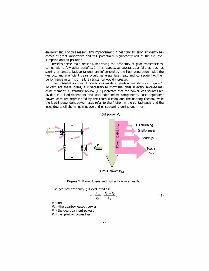
The potential sources of power loss inside a gearbox are shown in Figure 1. To calculate these losses, it is necessary to know the loads in every involved ma-chine element. A literature review [1-5] indicates that the power loss sources are divided into load-dependent and load-independent components. Load-dependent power loses are represented by the tooth friction and the bearing friction, while the load-independent power loses refer to the friction in the contact-seals and the loses due to oil churning, windage and oil squeezing during gear mesh.
Figure 1. Power losses and power flow in a gearbox
The gearbox efficiency η is evaluated as:
in
Vin
in
out
P
PP
P
Pη
−== , (1)
where: Pout - the gearbox output power Pin - the gearbox input power; PV - the gearbox power loss.
Input power Pin
Pow
er
loss
es
Plo
s Oil churning
Shaft- seals
Bearings
Tooth friction
Output power Pout
Pout
Pin

57
2. Analytical determination of the gearbox power losses
As mentioned above, the total power loss in a gearbox is represented by the sum of all loses in each gearbox element. According to [6], the total power loss of a gearbox, Pv,can be calculated by using the equation:
VXVSVB0VzVzV PPPPPP ++++= , (2)
where: PVz - gear power loss, due to the friction between the gear flanks; PVz0 - no-load gear power loss, due to windage, oil churning and oil squeezing during gear mesh; PVB - bearing losses; PVS - seal losses due to the interaction between the shafts and the seals; PVX - auxiliary losses from other gearbox components, such as: pumps, fans, heating, clutches or control system.
2.1. Gear power loss PVz
The overall average gear power loss, along the path of contact, at a gear
mesh, can be expressed, according to [6] as:
minVVz µPHP ⋅⋅= , (3)
where: HV - power loss factor; Pin - input power; µm - average coefficient of friction.
Even if different formulations are presented in the literature [7], [8], for the calculus of the power loss factor HV, [5] and [6] show that the relation of Ohlen-dorf [9], initially employed only for spur gears, applied with a deviation under 10%, may be used for helical gears too.
Therefore, in this approach, the power loss factor will be calculated with Oh-lendorf’s relation:
( )22
21α
b1
V εεε1βcosz
π
u
u1H ++−⋅
⋅⋅+= , (4)
where: u- gear ratio; z1 - pinion number of teeth; ßb - helix angle on the base circle; εα - profile contact ratio; ε1 - addendum transverse contact ratio of pinion; ε2 - addendum transverse contact ratio of driven gear. The average coefficient of friction µm depends on the applied load, the sliding
velocity, the lubricant properties, and the gear surface roughness. For its calcula-tion, Niemann’s [6] formulation is widespread accepted:
58
L25,0
a05,0
oil
2,0
redCCΣ
minbtm XRη
ρv
l/F048,0µ ⋅⋅⋅
⋅⋅= − , (5)
where: Fbt - circumferentiual force at base circle [N]; lmin- minim contact length of the gear pair (equal to face width in case of spur
gears [mm]; vΣC - sum velocity at operating pitch circle [m/s];
wttCΣ αsinv2v ⋅⋅= , (6)
ρredC - reduced radius of curvature at pitch point [mm];
bwt1wredC
βcos)1u(
uαsind5,0ρ
⋅+⋅⋅⋅= , (7)
oilη - dynamic oil viscosity at oil temperature [mPas];
Ra - arithmetic mean roughness [µm]; ( )2a1aa RR5,0R +⋅= , (8)
XL- lubricant correction factor (unit-less), which, for oil, is calculated as: 0651,0
btL
b
FX
−
= , (9)
b- face width [mm] vt- pitch line speed [m/s] αwt- working transverse pressure angle; dw1- pinion operating pitch diameter.
2.2. No- load gear power loss PVz0 The load independent gear losses, due to windage, oil churning and oil
squeezing during gear mesh, are influenced, among others, by the circumferential speed of the gears, the internal gearbox design, the operating temperature, the oil viscosity and the design of the rotating wheels. [6] proposes the following expres-sion for the calculation of the power losses in case of gearboxes with splash lubri-cation:
5,10Vz vhb1092,76P 6 ⋅⋅⋅⋅= − [kW], (10)
where: b- gear face width [mm]; h- oil immersion depth of the gear wheel [mm]; v- peripherical speed of the gear wheel [m/s]. 2.3. Bearing losses PVB
The losses in bearings are the result of the rolling and sliding friction which
occurs between the different parts of the bearing. Therefore, an accurate predic-

59
tion of losses has to take into account all these heat generation sources. The rela-tive new approach of SKF [10] considers four different losses to predict the torque loss in a bearing:
dragsealslrrVB MMMMM +++= , (11)
where: MVB - bearing torque loss; Mr r- rolling friction torque; Msl - sliding friction torque; Mseal - frictional torque of seals; Mdrag - frictional torque of drag losses, churning, splashing etc.. The conversion from torque losses to power losses can be done using the re-
lation:
55,9
nMP
⋅= , (12)
where: P- power [kW]; M- torque [Nmm]; n- rotational speed [rpm]. The rolling and the sliding friction torques Mrr and Msl are given by:
6,0rrrsishrr )nν(GφφM ⋅⋅⋅⋅= [Nmm], (13)
slslsl µGM ⋅= [Nmm], (14)
where: φish- inlet shear heating reduction factor (describes the influence of the lubri-
cating film thickness on the rolling friction); φrs- kinematic replenishment/starvation reduction factor (considers the lubri-
cant displacement in the contact zone due to over rolling, which generates a lower rolling friction torque);
Grr and Gsl- variables depending on bearing type, bearing mean diameter (dm=0,5(d+D)), the radial force Fr and the axial force Fa;
ν- kinematic viscosity of the lubricant [mm2/s]; n- rotational speed [rpm] µsl- sliding friction coefficient. The frictional torque in bearing seals is given by:
2sβs1sseal KdKM +⋅= [Nmm], (15)
where: KS1 and KS2- constants depending on the seal type, respective bearing type
and size; dS- seal counterface diameter [mm]; β- exponent depending on seal type and bearing type. The drag losses occur when a bearing is rotating in an oil bath, while being in-
fluenced by the bearing type, speed, oil level and oil viscosity. For a ball bearing, the drag losses are expresses by:
60
25mballmdrag ndKVM ⋅⋅⋅= [Nmm], (16)
where: Vm- variable depending on the oil level; Kball- bearing type related constant; dm- bearing mean diameter [mm]; n- rotational speed [rpm] The Bearing Calculator, accessible on skf.com/bearingcalculator, allows an
easy and fast calculation of the bearing losses for any type of standard bearing.
2.4. Seal losses PVS;
The power loss of the radial seals is the result of the friction between the lip
of the seal and the rotating shaft. Several computational models are presented in the literature, but due of its simplicity, we ilustrate here the approach of Kettler [11]:
nd1069,7P 2sh
6VS ⋅⋅⋅= − [kW] , (17)
where: dsh- shaft diameter [mm]; n- shaft rotational speed [rpm].
3. Materials and methods
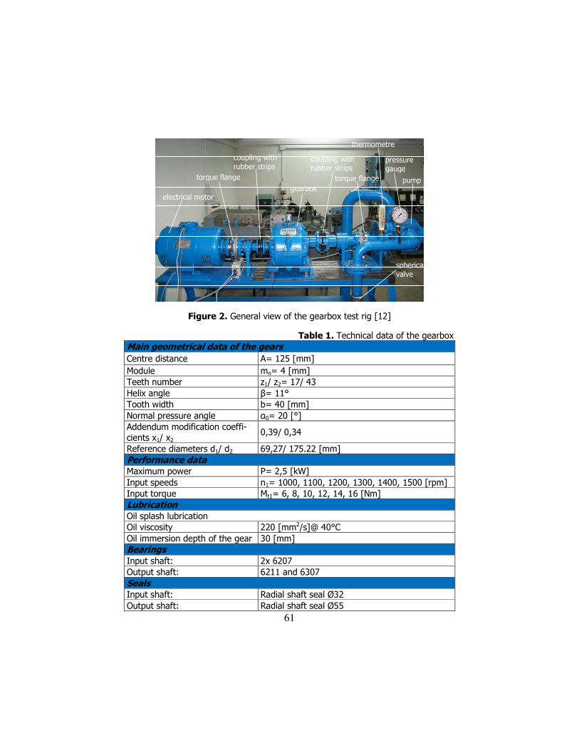
The aim of this project was to compare the analytically determined efficiency of a helical gearbox, with experimental measurements. The experiment was per-formed on the test rig shown in Figure 2. Technical data of the gearbox are pre-sented in Table 1.
As can be seen in Figure 2, for loading the gearbox a gear pump was used. For variation of the transmitted torque, a spherical valve has been placed on the pressure pipe of the gear pump.
The measurement of the gearbox transmitted load was done with two torque flanges (type T 1 0FS, made by HBM, Germany). One was mounted in the front of the input shaft, and the other behind the output shaft. These devices allowed measuring both the torque, and the speed. Three MP 60 modules (two for torque and one for speed), were used for data conversion.
In the first stage of the experiment, the gearbox was operated at the maxi-mum input speed (n1= 1.500 [RPM]), six different input torques (Mt1= 6, 8, 10, 12, 14, 16 [Nm]) being in turn used, while, the output torque measurement was per-formed for each operating condition corresponding to the different input torques. By means of Eq. (12), the corresponding input and output powers Pin and Pout re-spectively have been determined and the experimental efficiency was calculated with Eq. (1). In the meantime, the analytical efficiency of the gearbox was com-puted, using the approach presented in the previous chapter.
61
electrical motorgearbox
torque flange
coupling with rubber strips
coupling with rubber strips
torque flange pump
thermometre
pressure gauge
spherical valve
Figure 2. General view of the gearbox test rig [12]
Table 1. Technical data of the gearbox Main geometrical data of the gears
Centre distance A= 125 [mm]
Module mn= 4 [mm] Teeth number z1/ z2= 17/ 43 Helix angle β= 11° Tooth width b= 40 [mm] Normal pressure angle α0= 20 [°] Addendum modification coeffi-cients x1/ x2
0,39/ 0,34
Reference diameters d1/ d2 69,27/ 175.22 [mm] Performance data Maximum power P= 2,5 [kW] Input speeds n1= 1000, 1100, 1200, 1300, 1400, 1500 [rpm] Input torque Mt1= 6, 8, 10, 12, 14, 16 [Nm] Lubrication Oil splash lubrication Oil viscosity 220 [mm2/s]@ 40°C Oil immersion depth of the gear 30 [mm] Bearings Input shaft: 2x 6207 Output shaft: 6211 and 6307 Seals Input shaft: Radial shaft seal Ø32 Output shaft: Radial shaft seal Ø55
62
In the second stage of the experiment, the gearbox was operated in turn at six input speeds (n1= 1.000, 1.100, 1.200, 1.300, 1.400 1.500 [RPM]), while the input torque was maintained constant (Mt1= 16 [Nm]). Similarly to the first stage of the experiment, the gearbox efficiencies were also determined, both analytically and experimentally, for the six operating conditions.
4. Results and discussion
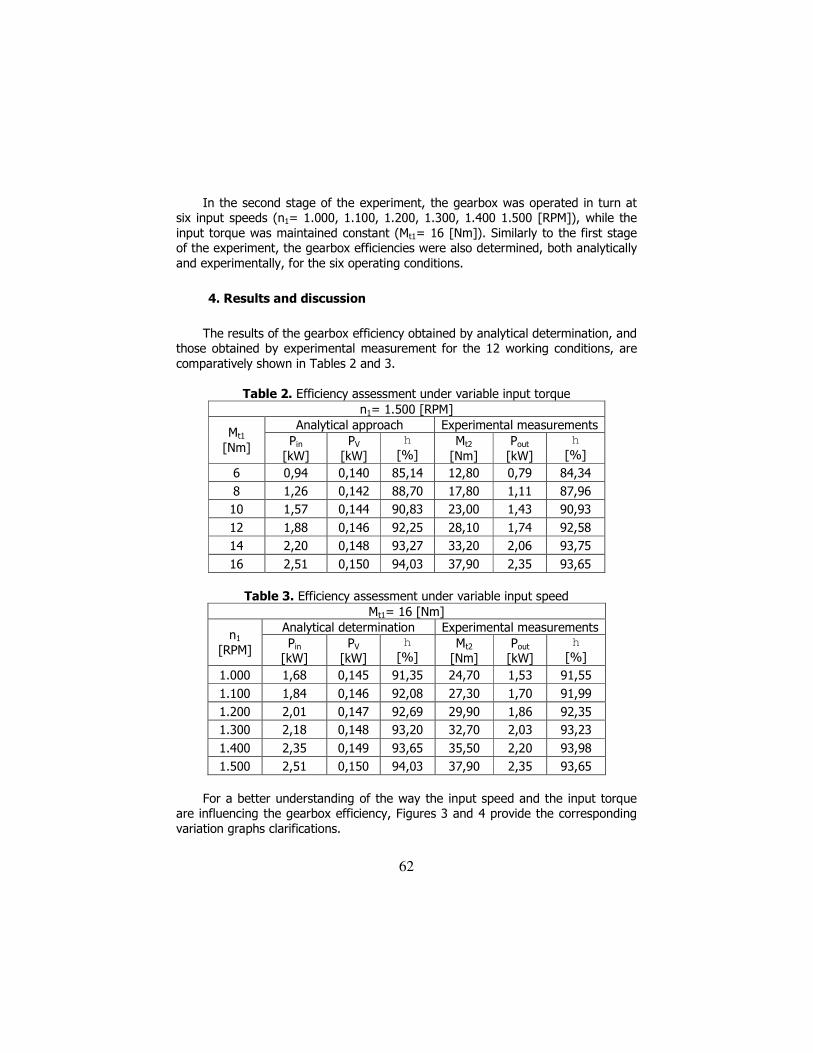
The results of the gearbox efficiency obtained by analytical determination, and those obtained by experimental measurement for the 12 working conditions, are comparatively shown in Tables 2 and 3.
Table 2. Efficiency assessment under variable input torque
n1= 1.500 [RPM] Analytical approach Experimental measurements
Mt1 [Nm]
Pin [kW]
PV
[kW]
h
[%] Mt2
[Nm] Pout
[kW]
h
[%]
6 0,94 0,140 85,14 12,80 0,79 84,34
8 1,26 0,142 88,70 17,80 1,11 87,96
10 1,57 0,144 90,83 23,00 1,43 90,93
12 1,88 0,146 92,25 28,10 1,74 92,58
14 2,20 0,148 93,27 33,20 2,06 93,75
16 2,51 0,150 94,03 37,90 2,35 93,65
Table 3. Efficiency assessment under variable input speed
Mt1= 16 [Nm] Analytical determination Experimental measurements
n1
[RPM] Pin
[kW] PV
[kW]
h
[%] Mt2
[Nm] Pout
[kW]
h
[%]
1.000 1,68 0,145 91,35 24,70 1,53 91,55
1.100 1,84 0,146 92,08 27,30 1,70 91,99
1.200 2,01 0,147 92,69 29,90 1,86 92,35
1.300 2,18 0,148 93,20 32,70 2,03 93,23
1.400 2,35 0,149 93,65 35,50 2,20 93,98
1.500 2,51 0,150 94,03 37,90 2,35 93,65
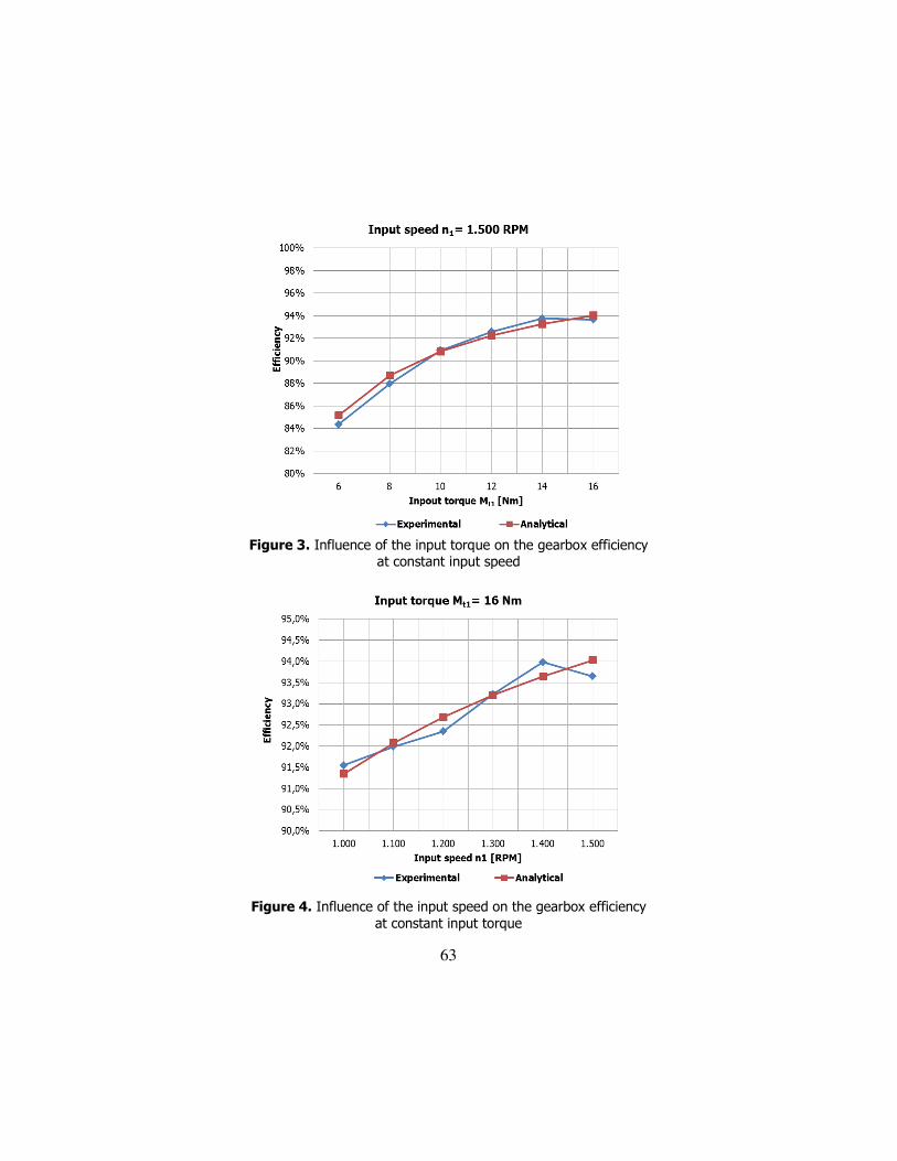
For a better understanding of the way the input speed and the input torque
are influencing the gearbox efficiency, Figures 3 and 4 provide the corresponding variation graphs clarifications.
63
Figure 3. Influence of the input torque on the gearbox efficiency
at constant input speed
Figure 4. Influence of the input speed on the gearbox efficiency
at constant input torque
64
Comparing the results of the gearbox efficiency acquired by analytical ap-proach and by experimental measurements, one can observe the values are very similar: a maximum calculated deviation between the two approaches is repre-sented by 0,4%.
First, by increasing the input torque from 6 to 16 Nm, while maintaining the input speed at 1.500 rpm, the gearbox efficiency increases too, from about 85% to nearly 94% (see Figure 3). Second, by increasing the input speed from 1.000 to 1.500 rpm, while maintaining the input torque at 16 Nm, the gearbox efficiency increases from nearly 91% to almost 94% (see Figure 4).
For the investigated operating conditions, it can be determined that, while maintaining the input speed at 1.500 rpm, by doubling the input torque from 8 to 16 Nm, the gearbox efficiency is improving by about 5%. Similarly, while maintain-ing the input torque at 16 Nm, by growing the input speed by 50% (from 1.000 to 1.500 rpm), the gearbox efficiency is correspondingly increased by about 2,5%.
The lower values of the efficiency assessment may be a result of the corre-sponding torque and speed operating conditions, in which the load independent losses have a significant contribution in the total amount of power loss. Such loses refer to the windage, oil churning and oil squeezing during gear mesh, the no-load bearing losses and the seal losses, which have a constant sum during the process. In addition, in the working domains where the transmitted power has higher val-ues, the contribution of the no-load losses becomes negligible in the total amount of power loss, even if the load dependent power losses are increasing (due to tooth and bearing friction).
Finally, the efficiencies obtained here are far below the values indicated by the literature in the field, according to which, for one-step gearboxes, the power loss does not exceed 2%, and, consequentially the efficiency should not be below 98%. The efficiency values obtained here can be explained by the fact that the maximum power that has been transmitted by the investigated gearbox during the testing was Pin≈2,5 kW. This power is well below the maximum power that can be trans-mitted by the gearbox (Pmax= 5 kW). This finding leads us to the conclusion that, in order to obtain a maximum efficiency, the gearboxes must be used at the power at which they were dimensioned
5. Conclusions
This paper presents analytical and experimental results concerning the effi-ciency investigation of a gear transmission. Improving gear transmission efficiency is motivated by several reasons, such as energy efficacy and environmental pres-sures.
We first describe an analytical model of the gearbox power losses based on mathematical equations previously proposed in the literature. Second, we perform experimental measurements concerning the efficiency of a helical gearbox. Using a test rig, we collected data in 12 distinct working conditions, which were different in

65
terms of input speed and the input torques. We showed that by increasing the in-put torque while maintaining the input speed constant, the gearbox efficiency in-creases too. Similarly, the gearbox efficiency increases with increasing the input speed, while maintaining the input torque constant. Third, we performed a com-parison between the results of the gearbox efficiency acquired by applying the analytical approach, and those acquired by experimental measurements. The out-come indicated similar values for the two approaches.
Our efficiency results are lower than previously reported in the literature, pos-sibly due to the low transmitting power by the used gearbox, relative to its maxi-mum possible power. Finally, we recommend gearboxes to be used at the power at which they were dimensioned, in order to obtain a maximum efficiency.
Acknowledgement
The work has been funded by the Sectoral Operational Programme Human Resources Development 2007-2013 of the Ministry of European Funds through the Financial Agreement POSDRU/159/1.5/S/132395.
References
[1] Höhn B. R., Michaelis, K., Hinterstoßer M., Optimization of gearbox efficiency, Goriva i Maziva, 2009, 49(4), pp. 462-480,. [2] Nutakor C., Klodowski A., Mikkola A., Sopanen J., Simulation Model of Power Losses for Sun and Planet Gear Pair Used in a Wind Turbine Gearbox, The 14th IFToMM World Congress, Taipei, Taiwan, 25-30 Octo-ber, 2015. [3] Diez-Ibarbia A., Fernández del Rincón A., Iglesias M. Viadero F., Ef-ficiency Analysis of Shifted Spur Gears, New Advances in Mechanisms, Transmissions and Applications, Mechanisms and Machine Science 2014, 17, pp. 65- 73. [4] Michaelis K., Höhn B., Hinterstoißer M., Influence factors on gearbox power loss, Ind. Lubr. Tribol. 2011, 63(1), pp. 46–55. [5] Marques P.M.T., Fernandes C., Martins R.C., Seabra J., Power losses at low speed in a gearbox lubricated wit hwind turbine gear oils with spe-cial focus on churning losses, Tribology International, 2013, 62, pp. 186-197. [6] Niemann G., Winter H., Maschinenelemente: Band 2, Springer, 2003 [7] Wimmer A.J., Lastverluste von Stirnradverzahnungen, Kostruktive Einfüsse, Wirkungsgradmaximerung, Tribologie, Fakultät für Maschinen-wesen der Technischen Universität München, 2006.

66
[8] Velex P, Ville F., Ananalytical approach to tooth friction losses in spur and helical gears-influence of profile modifications, Journal of Me-chanical Design, ASME Transactions, 2009. [9] Ohledorf H., Verlustleistung und Erwärmung von Stirnrädern, Ph. D. Thesis, T.U. München, 1958. [10] SKF, Rolling bearings, Pub. BU/P1 10000/ 3EN, August 2016. [11] Kettler J., Planetengetriebe-Sumpftemperatur, FVA - Forschungs-vorhaben Nr. 313, Heft 639, Forschungsbericht, 2002. [12] Korka Z., Research on vibration reduction in operation of cylindrical gearboxes, PhD Thesis, University, “Eftimie Murgu” of Resita, 2009.
Addresses:
• PhD. stud. Eng. Bogdan Clavac, “Eftimie Murgu” University of Reşiţa, Piaţa Traian Vuia, nr. 1-4, 320085, Reşiţa, [email protected]
• Lect., PhD. Eng. Zoltan-Iosif Korka, “Eftimie Murgu” University of Re-şiţa, Piaţa Traian Vuia, nr. 1-4, 320085, Reşiţa, [email protected]