Embed Size (px)
Citation preview

Efficiency Improvement of a tidal current turbine utilizing a larger area of
channel
Ki-Pyoung Kima, M. Rafiuddin Ahmed
b and Young-Ho Lee
c*
aMaritime R & D Centre, Korean Register of Shipping, Daejeon, Korea
bDivision of Mechanical Engineering, The University of the South Pacific, Suva, Fiji
cDivision of Mechanical and Energy Systems Engineering, Korea Maritime University, Busan,
Korea
Corresponding author: Prof. Young-Ho LEE
Division of Mechanical and Energy Systems Engineering
Korea Maritime University, 1 Dongsam-dong Youngdo-ku,
Busan, 606-791, Republic of Korea
Tel: +82-51-410-4293, Fax: +82-51-403-0381
Mobile: +82-10-3862-4293
E-mail: [email protected]
*ManuscriptClick here to view linked References

2
Efficiency Improvement of a tidal current turbine utilizing a larger area of
channel
Ki-Pyoung Kima, M. Rafiuddin Ahmed
b and Young-Ho Lee
c*
aMaritime R & D Centre, Korean Register of Shipping, Daejeon, Korea
bDivision of Mechanical Engineering, The University of the South Pacific, Suva, Fiji
cDivision of Mechanical and Energy Systems Engineering, Korea Maritime University, Busan, Korea
*Email: [email protected]
Abstract
There is a growing interest in utilizing tidal currents for power generation which has led to
extensive research on this source of renewable energy. The amount of energy that can be
extracted from tidal currents has been a topic of considerable interest to researchers for many
years; still, there is no consensus on the extent to which this resource can be exploited. A turbine
generates no power if it presents no resistance to the flow or if it presents so much resistance that
there is no flow through it. At the same time, the estimation of exploitable resource should take
into consideration the environmental, economic and social constraints. In view of these, the
design of efficient turbines driven by bi-directional tidal currents has been a challenge to
researchers for some time. There appears to be a general agreement among researchers that a
number of turbines spread over the width of the channel can extract more energy compared to an
isolated turbine. The present work is aimed at quantifying the improvement in the performance
of a given type of turbine by utilizing a larger area of the channel. Numerical experiments were
performed using the commercial CFD code ANSYS-CFX to study the performance of a bi-
directional cross-flow turbine by simulating two cases of i) a single turbine and ii) a number of
equally spaced turbines. It was found that the Coefficient of Power can be increased significantly
by employing a larger area of the channel.
Keywords: Ocean energy; Tidal current; Cross-flow turbine; CFD; Coefficient of power

3
Nomenclature
A inlet area of augmentation channel, m2
CP Power Coefficient
H1 length of augmentation channel from inlet to the axis of the turbine, m
P rotor Power, W
Po power output of turbine, W
Pw water power upstream of a given turbine, W
R blade radius, m
TSR tip speed ratio
V1 height of augmentation channel at inlet, m
Vaci mean velocity at augmentation channel inlet, m/s
Vri mean velocity at rotor inlet, m/s
ρ density of sea water, kg/m3
Ω angular velocity, rad/s
Uo freestream velocity, m/s
1. Introduction
Many countries surrounded by the oceans have rich marine energy resources, hence significant
amount of electric power can be generated from the oceans. Marine currents offer a regular and
predictable source of renewable energy [1]. Marine currents have only recently been looked at
seriously for large-scale power generation. A marine current turbine utilizes the kinetic energy of
marine currents and converts it to mechanical energy. Researchers have tried unsuccessfully to
employ conventional hydro-turbines for extracting energy from marine currents, because the
available head is too small. The main difference between high-head and free flow turbines is that
that the latter need large flow openings to capture as much water mass as possible with low
velocities and pressure. Conventional turbines, in contrast, are designed for high pressure and
relatively small water ducts where all the water is made to pass through the turbine. These
turbines have efficiencies as high as 90%. This is simply not possible for free flow turbines.
Even the Betz limit of 59.3% is considered unachievable [2] especially by propeller-type turbines
because the assumption in the Betz model is that the fluid flow remains rectilinear when passing
4
through the turbine and maintains a uniform distribution of its pressure on the turbine. Such a
uniformly distributed load leads to an overestimation of the force acting on the turbine and, as a
result, an overestimation of the turbine‟s output and efficiency. In reality, the fluid streams are
deflected from the rectilinear direction near the barrier, changing their motion to curvilinear
trajectories and reducing their pressure on the turbine [2].
A tidal current turbine has to extract energy from the bi-directional flow of water. There is a
growing interest in utilizing tidal currents for power generation and as a result, a surge in
research efforts directed at this renewable energy resource [3-11]. Garrett and Cummins [3] did a
theoretical analysis of an isolated turbine and an array of turbines in a channel. A turbine
generates no power if it presents no resistance to the flow or if it presents so much resistance that
there is no flow through it. They opined that an isolated turbine will inevitably have a current
through it with a speed lower than the ambient current, with a consequent reduction in power
generation below the metric of 30.5 oU per unit cross-section. They also concluded that an array
of turbines in the entrance to a bay plant will be most effective if it is spread across the width of
the entrance in order to minimize free flow past the turbines. They also felt that too many
turbines may choke the flow and reduce the power. Atwater and Lawrence [4] also did a
theoretical analysis to estimate the power generation potential in a channel. They argued that it is
inappropriate to use the free kinetic energy flux as the available resource because it does not
account for the reduction in flow as a result of increased resistance. For the determination of the
ideal turbine resistance, they suggested that a relation between friction and velocity needs to be
established; normally, the variation in the head loss with velocity is linear to quadratic. If the
relationship is quadratic, a maximum of 38% of the fluid power of a channel may be extracted,
and if the relationship is linear, the maximum drops to 25%. They also concluded that the flow
will reduce to 57% for the quadratic case and 50% for the linear case. Bryden and Couch [5]
studied the possible energy extraction from a simplified channel model and concluded that the
undisturbed kinetic flux density is a useful indicator of achievable resource. They suggested that
if higher levels of flow alteration are acceptable, then substantial fraction (called Significant
Impact Factor) of the energy may be available for extraction. In another paper, Garrett and
Cummins [6] performed a theoretical analysis for the cases of an isolated turbine and a tidal
fence occupying different fractions of a channel cross-section. They concluded that the
5
maximum efficiency factor 16/27 for a turbine in an infinite medium is increased in a channel.
They also concluded that the actual, rather than fractional power will increase if the ratio of
turbine area to channel area is increased. Sutherland et al. [7] found that at maximum power
extraction, the volume flux drops to 58% of that in the natural state and 2/3 of the original head
along the whole channel gets transferred to the turbine array. Blunden and Bahaj [8] performed a
review of the current understanding of tidal energy resources. The exploitable tidal current
resources and some analytical models of energy extraction were reviewed. They questioned the
lower achievable efficiency suggested by Gorban et al. [2] in view of the fact that some full-scale
prototype tidal current turbines achieved a power coefficient of 0.4 and above.
Sun et al. [9] suggested that estimation of the exploitable resource should not only take into
consideration the environmental, economic and social constraints, but also the hydrodynamic
resilience of the site in question and the fact that different technologies may give different
returns, depending on the nature of the site and the appropriateness of the technology. Their CFD
work focused on the impact of tidal current energy extraction on the local flow conditions. Their
model simulated the operational conditions for tidal energy extraction, where the flow is
constrained in the channel. A wake region is formed behind the tidal energy converter, which is
characterized by reduced velocity due to energy loss. Since the mean velocity in the wake is
lower than the free-stream velocity, the velocity outside the wake in a closed channel must be
higher than the free stream in order to maintain continuity of volume flow rate. Because of this
blockage effect, the flow is accelerated around the tidal current turbine. Their CFD results
demonstrated that the interaction of the tidal turbine with the flow is a complicated 3D problem.
The distortion of the free water surface will distort the wake and further influence the
performance of the turbine [9]. Kirke [10] in a research paper opined that the marine current
energy conversion technology still requires lot of research because it differs considerably from
the wind turbine technology. Significant amount of power can be obtained from tidal currents
and the researchers are still investigating different types of turbines and till now, none has
emerged as a clear winner. He reviewed some of the turbines that were being evaluated. It was
also felt by him and Blunden and Bahaj [8] that the ducted turbine, that was not found to be
economically advantageous for wind energy extraction, may be an attractive option for tidal

6
current energy extraction. Kirke [10] obtained a higher power coefficient, Cp, for the ducted
turbine compared to the open one.
Bahaj et al. [11] performed power and thrust measurements of horizontal axis marine current
turbines in a cavitation tunnel and a towing tank and studied the effects of tip speed ratio, the
blade pitch angle, blade tip immersion and yawed inflow. The rotor diameter was 800 mm and
had higher blockage ratio in the cavitation tunnel compared to the test tank. Since the blades for
such a turbine generate rotation mainly by lift, tip speed ratio (TSR) values of 5-7 resulted in
optimum performance. Under yawed conditions, the turbine power reduced significantly. In
another work on horizontal axis tidal current turbines, Coiro et al. [12] obtained the maximum
efficiency at TSR values of 3-4.
Another type of turbine that is attracting considerable attention nowadays is the cross-flow
turbine. This type of turbine is suitable even for very small heads. It is essentially an impulse
turbine. It can handle large quantities of water and also possesses flat efficiency characteristics.
In this type of turbine, the water passes over the blades twice, resulting in a higher momentum
transfer [13]. Some of the other advantages of a cross-flow turbine include cost effectiveness,
ease of construction, no problem of cavitation and independence of its efficiency to variations in
the flow rate [14,15]. Olgun [15] found a very small change in the maximum efficiency of their
cross-flow turbine when the head was changed from 8 m to 30 m.
2. Cross-flow turbine and the augmentation channel
The cross-flow turbine studied in the present work consisted of a rotor made up of 26 equi-
distant blades. An augmentation channel consisting of a nozzle at the inlet side and a diffuser at
the exit side surrounded the rotor, as shown in Fig. 1. The flow through the turbine is radial and
the water passes over the blades twice before exiting the rotor and entering the diffuser. This is a
bi-directional turbine and the design ensures equal output and efficiency for both the directions
of the flow. Due to this unique nature of flow - with the flow passage converging during the first
pass and diverging during the second pass through the blades and a non-uniform distribution of
flow in different blades, it is never desired to run the rotor full as the rotational force is not
obtained by reaction as is the case with Francis turbine. Some more of the characteristics of the
cross-flow turbine are: i) a wide range of rotational speeds can be selected, ii) turbine diameter

7
does not depend on the flow rate, iii) efficiency levels are satisfactory, iv) manufacturing is
simple and construction can be done at local facilities, and v) the bearings do not come in contact
with the flow [15]. Cross-flow turbines have been successfully designed and tested for ocean
energy extraction both experimentally and numerically and some of the works have been
published [16-18].
The augmentation channel in the present work was designed to generate power bi-directionally
without the use of additional devices. In all our related works, the turbine and augmentation
channel designs were similar to the present one; however, the shape of the augmentation channel
was modified based on the anticipated flow conditions as well as independent research [14]. In
the present work, since the source is tidal current, the channel shape shown in Fig. 1 was
employed.
In this research work, a cross-flow turbine which is suitable for low-speed and high flow rate is
designed and analyzed. Unlike most water turbines, the water passes through the rotor blades
transversely in a cross-flow turbine. As with a waterwheel, after passing the rotor, it leaves on
the opposite side. Therefore, the water strikes the blades twice, once at the inlet blades and
second at the exit blades, thus providing additional energy to the turbine and hence a higher
efficiency. The water enters the runner at the specific angle and transfers some of its kinetic
energy to the blades. The nozzle before the rotor causes acceleration of the flow and thus the
water enters the rotor with increased kinetic energy. The diffuser after the rotor increases the
pressure at the expense of the kinetic energy. After exiting the augmentation channel, the flow
mixes with the flow that passes around the augmentation channel which is normally at a higher
velocity than the freestream velocity. The resulting velocity gradient creates a shear layer with
high turbulence levels, which causes rapid mixing of the two flows.
3. Design procedure
The numerical experiments were performed in a water channel having a length of 87 m and a
cross-section of 26.1 m x 26.1 m. The design freestream velocity was chosen as 2.5 m/s in this
work. The inlet flow was assumed to be uniform across the height and width of the water
channel. The inlet area of the augmentation channel (A) is 8.7 m 8.7 m and the total length is

8
17.4 m. At the inlet to the turbine, the augmentation channel height reduces to 4.35 m. The
internal and external diameters of the rotor are 3.85 m and 6.05 m respectively. The 3D CAD
tool used was CATIA [19]. Twenty six blades were provided between the inner and outer
periphery of the rotor. The blades make an angle of 30o with the tangent to the rotor at the outer
periphery and a right angle with the tangent to the rotor at the inner periphery. Each of the blades
has an axial length of 8.7 m, a radial length of 1.1196 m and a thickness of 66 mm. The
augmentation channel, which served as a nozzle at the inlet side and as a diffuser at the exit side,
is shown in Fig. 2. It was modeled in two halves and placed on either side of the turbine. The
curved surface of the augmentation channel was designed to be tangential to the blade at both the
inlet and outlet sides. The clearance of the turbine and housing was 20.6 mm. The geometric
details of the rotor and the augmentation channel are shown in Table 1. The flatter edge of the
augmentation channel was curved near the turbine inlet to ensure smooth entry of the flow to the
blades. The direction of the flow entering the rotor is controlled by the shape of the nozzle,
indicating the importance of the nozzle shape. The complete blades are shown in Fig. 3.
4. Grid generation
The commercial code ANSYS-Icem CFD was used for mesh generation. To get a higher
accuracy, hexahedral grids were generated. About 1 million nodes were provided on the
augmentation channel. The meshed augmentation channel is shown in Fig. 4. It was found easier
to generate the grids on one blade and then rotate the whole mesh by 360o. About 200,000 nodes
were provided on each blade; hence the total number of nodes on all the blades was about 5.2
million. Figure 5 shows the meshed rotor. In the water tunnel, the number of nodes was about 2
million. Thus, the total number of nodes in the entire domain exceeded 8 million.
5. Computational procedure
The finite volume commercial code ANSYS-CFX was used in the present computations. This
code was tested for the analysis of a similar turbine [16,17]. A good agreement between
numerical and experimental results was observed for the flow characteristics through the
augmentation channel and the rotor. The work also involved studying the effect of non-
dimensional wall distance y+ on the turbine performance; it was found that for y+ 50, the

9
accuracy does not get affected [20]. In this study three turbulence models were also „tested‟ for
the analysis of a cross-flow turbine. The k- SST turbulence model gave good results in the
simultaneous analysis of both high and low energy areas in a complicated flow field with
relatively low grid dependence. Hence, the k- SST turbulence model was chosen for turbulence
modeling. To perform the present CFD analysis, 8-10 parallel computers were employed. The
inlet velocity was set at 2.5 m/s with its direction normal to the water tunnel inlet face. The
boundary condition at the outlet was set to zero (atmospheric) pressure. The density of the water
was taken as 1025 kg/m3. The boundary conditions for the augmentation channel were set to
„wall‟ (no-slip condition). Figure 6 shows the schematic diagram of the water tunnel and a single
turbine and augmentation channel set-up inside the tunnel (case 1). The other case (case 2) of
multiple equally spaced turbines was simulated by placing four solid walls, with no slip
boundary conditions, around a turbine and augmentation channel set-up at a distance of a quarter
of the augmentation channel inlet width/height, which comes to 2.175 m. Thus, the case of
multiple turbines (with their augmentation channels) placed side-by-side with a reduced spacing
between them and thus occupying a greater area of the channel, was simulated. The freestream
velocity was same as the previous case. The angular velocity (Ω) was varied to get different
values of TSR. The tip speed ratio was calculated taking the mean velocity at the rotor inlet as
the reference velocity due to the uniqueness of this study. The water velocity at the entrance to
the augmentation channel (Vaci), at the entrance to the rotor (Vri), the power output and the
Coefficient of power (Cp) were computed at these values of TSR. The results for both these
cases are presented in the following section.
6. Results and discussion
6.1. Flow characteristics
The main focus of the present work was on the performance analysis of the bi-directional cross-
flow turbine for the two cases of a single turbine and multiple, equally spaced, turbines.
However, as the design of the turbine is unique, the flow characteristics through the nozzle, the
rotor and the diffuser were studied in detail for both the cases. For both the cases, the flow was
found to accelerate on the sides outside of the augmentation channel due to the resistance to the
flow offered by the augmentation channel and the closely-spaced turbine blades, which forces
the incompressible flow to divert away from the augmentation channel. The tidal current turbine,

10
introduced in to the tidal current, is known to reduce the flow to as much as 50% of the flow in
the absence of the turbine [4]. However, for this particular area reduction and number of blades,
the reduction in velocity is larger. Figure 7 shows the velocity vectors for the flow through the
augmentation channel and the rotor blades for case 1. It can be seen that the velocity at the
entrance of the augmentation channel is less than 1 m/s. The flow is found to separate on the
turbine blades as well as in the diffuser. The flow separation is likely to affect the performance of
the turbine significantly. The blades rotate through the fluid generating the viscous forces at the
layer near the solid surface and the viscous forces cause flow separation between two blades. The
flow separation is influenced by the Reynolds number of the local flow. When the adverse
pressure gradient is reasonably strong, the flow next to the wall reverses direction, resulting in a
region of backward flow. The reversed flow meets the forward flow at some point at which the
fluid near the surface is transported out into the mainstream. As a result, the flow separates from
the wall. At lower Reynolds numbers, the reversed flow downstream of the point of separation
forms part of a large steady vortex behind the surface. At higher Reynolds numbers, when the
flow has boundary layer characteristics, the flow downstream of separation is unsteady and
frequently chaotic [21]. The separation is known to increase the drag, particularly pressure drag
which is caused by the pressure difference between the front and rear surfaces of an object. For
this reason much effort and research has gone into the design of aerodynamic and hydrodynamic
surfaces which delay flow separation and keep the local flow attached for as long as possible. It
is interesting to observe that the flow separates at the trailing edge of the blades resulting in a
region of re-circulating flow in the region. The flow through the diffuser section will get affected
by the pressure in the near-wake of the augmentation channel. The velocity vectors for the flow
through the augmentation channel and the rotor blades for case 2 are shown in Fig. 8. The
velocity at the entrance of the augmentation channel is higher than case 1 and more than 1 m/s.
The rotational speed of the turbine was varied in the present work such that TSR values varied
from 0.15 to 2.7. Figure 9 shows the variation of the velocity at the entrance to the augmentation
channel and the rotor with TSR for the two cases. The freestream velocity is constant at 2.5 m/s
for all the cases studied in the present work. It is interesting to note that the velocity at the
entrance of the augmentation channel (Vaci) is considerably reduced compared to the freestream
velocity (Uo) for both the cases; however, for case 2, the mean velocity is nearly twice compared
to case 1, indicating that if more turbines are placed in a channel close to each other, the kinetic

11
energy available to the turbine will be significantly higher, as the flow is forced to pass through
the turbine and not go around the augmentation channel. The velocity inside the nozzle increases
further as the flow approaches the rotor blades. It can be seen from Fig. 7 and Fig. 8 that most of
the flow enters the blades at the centre of the duct at any instant. For the blades in the first stage
(when the flow is passing over the blades for the first time), the acceleration of the flow on the
upper surface (suction) and the deceleration on the lower surface (higher pressure) can be seen
for both the cases. This shows that some of the power generation takes place due to the pressure
difference on the two sides of the blades. The water can be seen to accelerate as it exits the first
stage blades and flows across towards the second stage blades. However, there is a region of
recirculating flow under the region of accelerated flow. To clearly understand the mode of
energy transfer from the water to the blades during the second stage, an enlarged view of the
rotor showing the flow interaction with the blades for case 2 was analyzed. This is shown in Fig.
10. It can be seen from this figure that the accelerated flow does not enter the second stage
blades tangentially. It strikes the blades at an angle and due to the resulting impulse, a force is
exerted on the blades. The water transfers some of its momentum to the blades causing them to
rotate. Figure 11 shows the pressure contours in and around the augmentation channel and in the
rotor for case 2. The pressure starts to build in front of the augmentation channel as the flow
decelerates. However, the pressure starts reducing outside of the augmentation channel as the
flow starts accelerating in the free gap between the augmentation channel and the separating wall
between two turbines. In the region of minimum area in the gap, a strong suction can be seen.
The velocity recorded here was slightly more than twice the freestream velocity. Inside the
augmentation channel, the pressure is higher than atmospheric at every point with a higher
pressure at the inlet section where the area is maximum. As the area reduces towards the rotor
inlet, the velocity increases (Fig. 8) and consequently, the pressure reduces a little. As the flow
enters the blades, the flow possesses both high velocity and higher pressure. It should, however,
be noted that a direct application of energy balance between the inlet of the augmentation
channel and the rotor blades will not be appropriate, as the streamlines are curving and most of
the flow is entering only some of the blades. As the water exits the first stage blades and flows
towards the second stage blades, it still possesses high pressure and velocity except for the
recirculating region where the pressure is below atmospheric. At the exit of the rotor, the

12
pressure is lower, which starts to increase as the flow moves towards the exit of the
augmentation channel (diffuser).
6.2. Power output and power coefficient
Figure 12 shows the power output for the two cases. The maximum power output of 54 kW in
case 1, found at a TSR of 0.9 is significantly smaller compared to case 2. The torque for both the
cases reduced from its maximum at the lowest TSR to the maximum TSR. However, the torque
and hence the power output increased considerably for case 2, where the flow was forced to take
place through the augmentation channel and the rotor due to the small gap between one turbine
set-up and the other. The maximum power output recorded for this case was slightly above 300
kW at a TSR of nearly 1.3. Accordingly, the Coefficient of power, Cp, was considerably higher
for case 2 for all the tip speed ratios studied in this work, as shown in Fig. 13. Interestingly, the
minimum Cp for case 2 was higher than the maximum Cp for case 1, highlighting the importance
of utilizing a larger area of the channel for higher power extraction. As discussed in the previous
section, this resulted in a considerably higher flow of water through the turbine which resulted in
a higher power generation. The maximum Cp recorded for case 2 was 0.51, which is more than 5
times the maximum Cp for case 1. The reasons for the lower Cp are the high resistance to the
flow offered by the augmentation channel‟s nozzle and the closely-spaced blades, the flow
separation between the turbine blades and in the diffuser. It is felt that the large number of blades
and the narrow spacing between the blades adversely affect the smooth flow of water. Therefore,
to improve the turbine performance, the number of blades and the clearance should be optimized
by studying the effect of these parameters on the flow characteristics to reduce the flow
resistance and to control the separation. The non-streamlined shape of casing also influences the
whole turbine system flow, therefore the effect of shape should be considered when analyzing the
whole turbine system. Although a higher Cp was obtained for case 2, it is felt that the
performance can be improved by designing a nozzle with a slightly larger area at the exit, which
will also be helpful when the flow takes place in the opposite direction. Utilizing a large area of a
real tidal flow channel may not always be practical as it will affect the local flow conditions that
may include undesirable conditions for boats and for marine life. In some cases e.g. when the
channel is formed between reefs, the effect on the local flow conditions may be undesirable.
13
The maximum power output and coefficient were obtained at a TSR of around 1. This shows that
the cross-flow turbine behaves more like an impulse turbine rather than a lift-driven turbine as is
the case with horizontal axis tidal turbines.
The power available in the water upstream of a given turbine (Pw) is given by
31 2 oPw AU (1)
In the present case, the quantity Pw is fixed as the freestream velocity and the augmentation
channel inlet area is fixed. It is seen in the above section that the rotor power output and Cp
increase as more turbines are placed in the water channel. This is compared with the theoretical
power generated by a turbine that is placed in a freestream velocity of Uo from ref. [6], given by
2 2
3 4 3 4 3
4 3
( )( )1 2 2 o
u u u u uP A
u u U
(2)
where u3 is the velocity in the wake region and u4 is the accelerated flow velocity in the gap
between the turbine and the channel walls. The values of u3 and u4 were taken from the results of
the present work. It is found that the power for case 2 increases about 2.3 times compared to case
1, which is considerably less than the power increase obtained from our numerical work. The
theory of ref. [6] estimates the amount of power that can be extracted from the flow; however,
only a part of that power may be productive in rotating the turbine. The internal losses for case 1
may be higher compared to case 2.
7. Conclusions
CFD analysis of a cross-flow tidal current turbine equipped with an augmentation channel was
carried out to study the effect of utilizing a larger channel area on the flow characteristics, the
power output and the Coefficient of power. It was found that when a larger area of the channel is
utilized, the flow velocity through the turbine increases as less of the flow bypasses the turbine
system and flows through the gap between the turbine and the channel or between two turbines.
In the present study, the flow velocity through the turbine and augmentation channel and the
rotor almost doubled when the case of multiple equally-spaced turbines was simulated by placing
solid walls with no-slip boundary conditions around the turbine and augmentation channel set-up
at a distance of a quarter of the augmentation channel inlet width and height. The maximum
power output increased from nearly 54 kW to slightly above 300 kW as a result. The Coefficient

14
of power also increased by more than 5 times for this case.
References
[1] Charlier RH. A “ Sleeper” awakes: tidal current power. Renewable and sustainable energy
reviews 2003;7:187-213.
[2] Gorban AN, Gorlov AM, Silantyev VM. Limits of the turbine efficiency for free fluid flow.
Journal of the Energy Resources Technology 2001;123:311-7.
[3] Garrett C, Cummins, P. Generating power from tidal currents, ASCE Journal of Waterway,
Port, Coastal and Ocean Engineering 2004;130:114-8.
[4] Atwater JF, Lawrence GA. Limitations of tidal power generation in a channel, Proceedings of
the 10th
World Renewable Energy Congress, Glasgow, Scotland; 2008. p. 947-52.
[5] Bryden, IG, Couch SJ. How much energy can be extracted from moving water with a free
surface: A question of importance in the field of tidal current energy. Renewable Energy 2007;
32:1961-6.
[6] Garrett C, Cummins, P. The efficiency of a turbine in a tidal channel. Journal of Fluid
Mechanics 2007; 588: 243-51.
[7] Sutherland G, Foreman M, Garrett C. Tidal current energy assessment for Johnstone strait,
Vancouver island, Journal of Power and Energy 2007; 221:147-57.
[8] Blunden LS, Bahaj AS. Tidal energy resource assessment for tidal stream generators. Journal
of Power and Energy 2007;221:137-146.
[9] Sun X, Chick JP, Bryden IG. Laboratory-scale simulation of energy extraction from tidal
currents. Renewable Energy 2008; 33:1267-74.
[10] Kirke B. Developments in ducted water current turbines. Sustainable Energy Centre,
University of South Australia, available online at
www.cyberiad.net/library/pdf/bk_tidal_paper25apr06.pdf
[11] Bahaj AS, Molland AF, Chaplin JR, Batten WMJ. Power and thrust measurements of
marine current turbines under various hydrodynamic flow conditions in a cavitation tunnel and a
towing tank. Renewable Energy 2007; 32:407-26.
[12] Coiro DP, Maisto U, Scherillo F, Melone S, Grasso, F. Horizontal axis tidal current turbine:
numerical and experimental investigations, Proceedings of Owemes, Civitavecchia, Italy; 2006.
[13] Reddy H, Seshadri V, Kothari DP. Effect of draft tube size on the performance of a cross-
flow turbine. Energy Sources 1996;18:143-149.

15
[14] Prasad D, Zullah MA, Ahmed MR, Lee YH. Effect of front guide nozzle shape on the flow
characteristics in an augmentation channel of a direct drive turbine for wave power generation.
Science China - Technological Sciences 2010;53:46−51.
[15] Olgun H. Investigation of the performance of a cross flow turbine. International Journal of
Energy Research 1998;22:953–64.
[16] Choi YD, Kim CG, Lee YH. Effect of wave conditions on the performance and internal
flow of a direct drive turbine. Journal of Mechanical Science and Technology 2009;23:1693-
1701.
[17] Choi YD, Kim CG, Kim YT, Song JI, Lee YH. A performance study on a direct drive hydro
turbine for wave energy converter. Journal of Mechanical Science and Technology 2010;
24:2197-206.
[18] Kim KP, Ahmed MR, Hwang, YH and Lee YH. Conceptual design of a 100 kW energy-
integrated type bi-directional tidal current turbine. In: Proceedings of the 10th
Asian International
Conference on Fluid Machinery. Kuala Lumpur, Malaysia; 2009, Paper 212.
[19] www.3ds.com/products/catia
[20] Choi YD, Cho YJ, Kim YT, Lee YH. Performance and internal flow of a cross-flow type
turbine for wave power generation. Journal of Fluid Machinery 2008;11:22-9.
[21] Anderson, J. D. Jr. Fundamentals of Aerodynamics. 3rd
ed. New York: McGraw Hill; 2001.

16
List of Tables:
Table 1. Geometric details of cross-flow turbine and augmentation channel
List of Figures: Fig. 1. Schematic diagram of the rotor and the augmentation channel.
Fig. 2. A three-dimensional view of the augmentation channel.
Fig. 3. A three-dimensional view of the rotor blades.
Fig. 4. The meshed augmentation channel.
Fig. 5. The meshed rotor.
Fig. 6. Schematic diagram of the water channel with the set-up.
Fig. 7. Velocity vectors showing the flow of water through the augmentation channel and the
rotor for case 1.
Fig. 8. Velocity vectors showing the flow of water through the augmentation channel and the
rotor for case 2.
Fig. 9. Inlet velocities at augmentation channel inlet and turbine inlet at different tip speed ratios
for the two cases.
Fig. 10. Velocity vectors showing the flow of water through the rotor.
Fig. 11. Iso-pressure contours in the main flow domain.
Fig. 12. Power output of the turbine for the two cases.
Fig. 13. Coefficient of power for the two cases.

Table 1: Geometric details of cross-flow turbine and augmentation channel
Number of blades 26
Blade angle at outer periphery 30°
Blade angle at inner periphery 90°
Axial length of blade 8,700 mm
External diameter 6,050 mm
Internal diameter 3,850 mm
Clearance of turbine & housing 20.6 mm
Length of blade 1,119.6 mm
Thickness of blade 66 mm
Total length of augmentation channel (2 × H1) 17.4 m Cross-section of augmentation channel at inlet (V1 × width) 8.7 m × 8.7 m
Cross-section of augmentation channel at outlet 8.7 m × 4.35 m
Table 1

Fig. 1. Schematic diagram of the rotor and the augmentation channel.
Figure 1

Fig. 2. A three-dimensional view of the augmentation channel.
Figure 2

Fig. 3. A three-dimensional view of the rotor blades.
Figure 3

Fig. 4. The meshed augmentation channel.
Figure 4

Fig. 5. The meshed rotor.
Figure 5

Fig. 6. Schematic diagram of the water channel with the set-up (all dimensions are in mm).
26100
87000
8700
17400
Figure 6

Fig. 7. Velocity vectors showing the flow of water through the augmentation channel and the rotor for case 1.
Figure 7
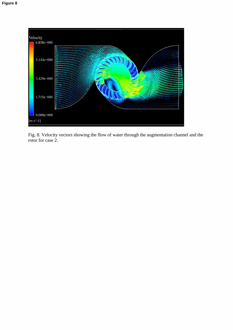
Fig. 8. Velocity vectors showing the flow of water through the augmentation channel and the rotor for case 2.
Figure 8
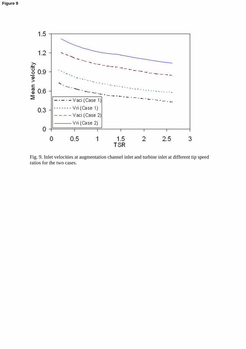
Fig. 9. Inlet velocities at augmentation channel inlet and turbine inlet at different tip speed ratios for the two cases.
Figure 9

Fig. 10. Velocity vectors showing the flow of water through the rotor.
Figure 10

Fig. 11. Iso-pressure contours in the main flow domain.
Figure 11

Fig. 12. Power output of the turbine for the two cases.
Figure 12

Fig. 13. Coefficient of power for the two cases.
Figure 13