Embed Size (px)
Citation preview

To deliver high levels of care, you need to make quick, informed decisions – at the scene of an emergency and across the entire course of treatment. You need your equipment to be easy to use as you care for a patient, monitor developments in the patient’s condition during transport to the hospital, and as you care for your patient in the hospital. We designed the Efficia DFM100 defibrillator/monitor so you can meet the demands of patient care in the pre-hospital and hospital environment effectively and consistently. With field-proven Philips technology, the Efficia DFM100 offers core functionality with a scalable feature set and improved cost of ownership, allowing you to enhance patient care, no matter where the patient is located.
Key advantages
• Dependable and easy to use
• Scalable feature set
• Enhanced cost of ownership
At the core of your criticalcare emergency response
Defibrillator/monitor
DFM100
Efficia
Parameter Specification
Approximate dimensions 23.5 cm (H) x 29 cm (W) x 20.5 cm (D); 9.25 in (H) x 11.4 in (W) x 8 in (D)
Approximate weight (without battery)
5.66 kg; 12.5 lbs
Standard operator position Within one meter (3 feet) of the device.
Power Rechargeable lithium-ion battery; AC power using a protectively grounded outlet.
Alarm tone and voice message volume range
Maximum - 85 dB(A), minimum - 45 dB(A).
Alarm tone volumes: Imminent shutdown – Continuous tone alternating between 1000 and 2100 Hz.High priority – tone of 960 Hz lasting 0.5 second repeated every second.Medium priority – tone of 480 Hz lasting 1 second repeated every two seconds.Low priority – tone of 480 Hz lasting 0.25 second repeated every two seconds.
Visual alarm characteristics High priority (Red) – flashing at 2 Hz with 50% duty cycle (a .25-second flash twice every second).Medium priority (Yellow) – flashing at 0.5 Hz with 50% duty cycle (a 1-second flash every other second).Low priority (Cyan) – constant on.
Parameter Specification
Waveform Biphasic truncated exponential. Waveform parameters adjusted as a function of patient impedance.
Shock delivery Via multifunction electrode pads or paddles.
Shock series Configurable energy escalation in a series.
Leads off sensing and PCI sensing for pads/paddles:
Apply 500nA rms (571Hz); 200uA rms (32KHz)
Specifications
General
Defibrillator
2

Delivered energy accuracy Nominal delivered energy vs. load impedance
Selected energy
Load impedance (ohms) ±2%
25 50 75 100 125 150 175
1 J 1.2 1.3 1.3 1.2 1.1 1.0 0.9
2 J 1.7 2.0 2.1 2.0 1.9 1.7 1.6
3 J 2.6 3.0 3.1 3.2 3.2 3.1 2.9
4 J 3.5 4.0 4.2 4.3 4.4 4.5 4.3
5 J 4.3 5.0 5.2 5.4 5.5 5.6 5.4
6 J 5.2 6.0 6.3 6.5 6.6 6.7 6.5
7 J 6.1 7.0 7.3 7.6 7.8 7.8 7.6
8 J 6.9 8.0 8.4 8.6 8.9 8.9 8.7
9 J 7.8 9.0 9.4 9.7 10 10 9.8
10 J 8.7 10 10 11 11 11 11
15 J 13 15 16 16 17 17 16
20 J 17 20 21 22 22 22 22
30 J 26 30 31 32 33 33 33
50 J 43 50 52 54 55 56 54
70 J 61 70 73 76 78 78 76
100 J 87 100 105 108 111 111 108
120 J 104 120 126 130 133 134 130
150 J 130 150 157 162 166 167 163
170 J 147 170 178 184 188 189 184
200 J 173 200 209 216 222 223 217
The delivered energy accuracy is ±10% or ±1J whichever is greater for all energy settings.
Charge times: Less than 5 seconds to the recommended adult energy level (150 joules) with a new fully-charged battery installed.
Less than 6 seconds to the selected energy level (up to 200 joules) with a new fully-charged battery installed, even after the delivery of 15 discharges at maximum energy.
Less than 15 seconds to the selected energy level while connected to AC power only, even when operating on 90% of the rated mains voltage.
The device powers on in manual defibrillation mode ready to deliver shock in less than:• 23 seconds with AC power only and at 90% of rated mains voltage.• 15 seconds with a new, fully-charged battery even after 15 discharges of maximum energy.
Time from the initiation of analysis in AED mode until ready to deliver shock is less than 20 seconds with: • AC power only and at 90% of rated mains voltage.• A new, fully charged battery even after 15 discharges of maximum energy.
The device powers on in AED mode ready to deliver shock in less than:• 32 seconds with AC power only and at 90% of rated mains voltage.• 24 seconds with a new, fully charged battery even after 15 discharges of maximum energy.
Patient impedance range Minimum: 25 ohm (external defibrillation); 15 ohm (internal defibrillation); Maximum: 250 ohm. Actual functional range may exceed these values.
3
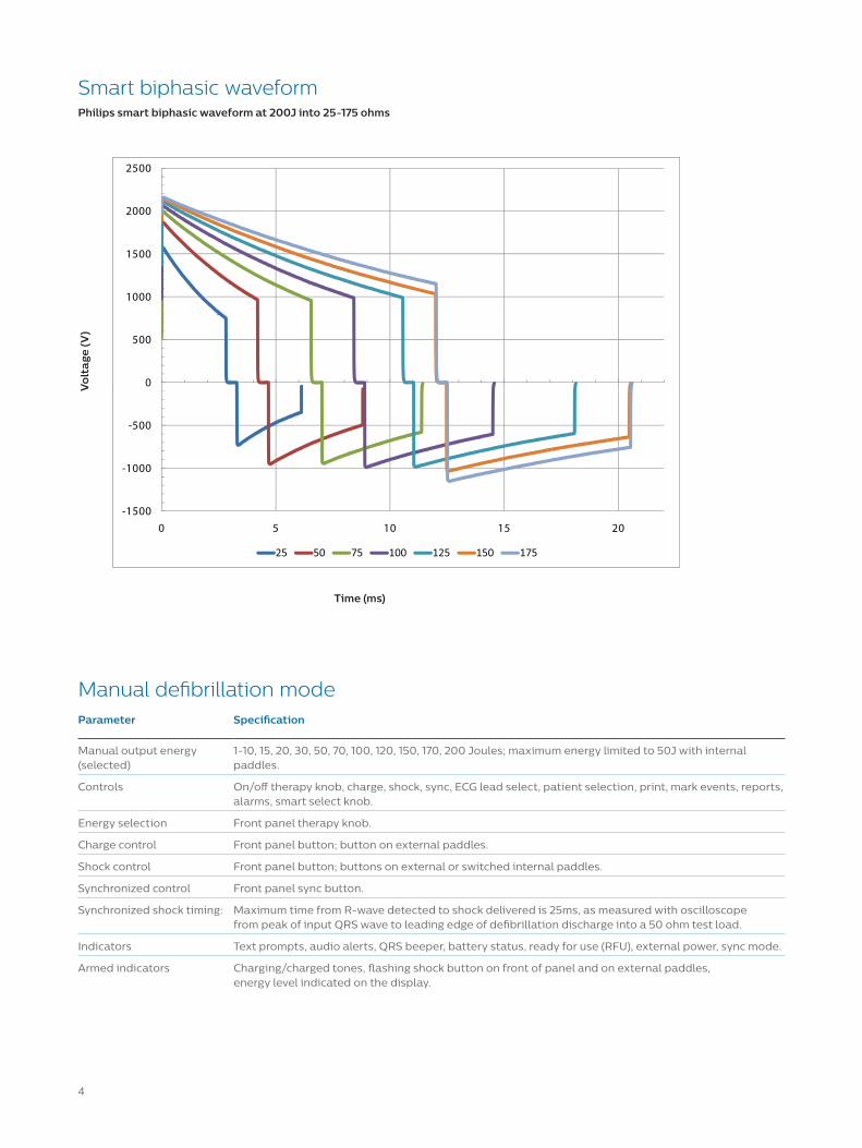
Smart biphasic waveformPhilips smart biphasic waveform at 200J into 25-175 ohms
0
500
1000
1500
2000
2500
-1500
-1000
-500
0 5 10 15 20
Vo
lta
ge (V
)
Time (ms)
Parameter Specification
Manual output energy (selected)
1-10, 15, 20, 30, 50, 70, 100, 120, 150, 170, 200 Joules; maximum energy limited to 50J with internal paddles.
Controls On/off therapy knob, charge, shock, sync, ECG lead select, patient selection, print, mark events, reports, alarms, smart select knob.
Energy selection Front panel therapy knob.
Charge control Front panel button; button on external paddles.
Shock control Front panel button; buttons on external or switched internal paddles.
Synchronized control Front panel sync button.
Synchronized shock timing: Maximum time from R-wave detected to shock delivered is 25ms, as measured with oscilloscope from peak of input QRS wave to leading edge of defibrillation discharge into a 50 ohm test load.
Indicators Text prompts, audio alerts, QRS beeper, battery status, ready for use (RFU), external power, sync mode.
Armed indicators Charging/charged tones, flashing shock button on front of panel and on external paddles, energy level indicated on the display.
Manual defibrillation mode
4

Parameter Specification
AED energy profile 150 joules (factory default) for adult/50 J for infant/child nominal into a 50 ohm test load.
AED controls On/off, shock.
Text and voice prompts Extensive text/audible messages guide user through a user-configured protocol.
Indicators Monitor display messages and prompts, voice prompts, battery status, RFU, external power.
Armed indicators Charging/charged tones, flashing shock button, energy level indicated on the display.
ECG analysis Evaluates patient ECG and signal quality to determine if a shock is appropriate and evaluates connection impedance for proper defibrillation pad contact.
Shockable rhythms SMART analysis is designed to shock ventricular fibrillation, ventricular flutter and polymorphic ventricular tachycardia. It is designed to avoid delivering a shock for rhythms that are commonly accompanied by a pulse or rhythms that would not benefit from an electrical shock.
Shock advisory algorithm sensitivity
Meets AAMI DF39 requirements and AHA recommendations; adult: ventricular fibrillation - 90% with lower confidence limit (LCL) of 87%, polymorphic ventricular tachycardia and ventricular flutter - 75% with LCL of 67%; infant/child: ventricular fibrillation - 90% with LCL of 87%.
Shock advisory algorithm specificity
Meets AAMI DF39 requirements and AHA recommendations; normal sinus rhythm - 99% with LCL of 97%; Asystole - 95% with LCL of 92%; other non-shockable rhythms - 95% with LCL of 88%.
Parameter Specification
Inputs Up to 3 ECG waves may be viewed on the display and up to 2 waves printed simultaneously. Lead I, II or III is obtained through the 3-wire ECG cable and separate monitoring electrodes. With a 5-Lead ECG cable, leads aVR, aVL, aVF and V can also be obtained. Pads ECG is obtained through two multifunction electrode pads.
Lead fault Messages and dashed lines appear on the display if an electrode or lead becomes disconnected.
Pad fault Dashed line appears on the display if a pad becomes disconnected.
Heart rate display Digital readout on the display from 16 to 300 bpm (adult patient category) or 16 to 350 bpm (infant/child), with an accuracy of ±10% or ±5 bpm whichever is greater.
Heart rate/arrhythmia alarms
HR high/low, asystole, VFIB/V-TACH, VTACH, extreme tachy, extreme brady, PVC rate, pacer not capture, pacer not pacing.
Common mode rejection 105 dB for leads ECG, 96 dB for pads ECG.
ECG size: 1/4x, 1/2x, 1x, 2x, 4x, auto gain (1x gain is 10mm/mV on the printed strip).
ECG waveforms: Displayed at a fixed timebase of 25 mm/second (printer) ±5%, 25 mm/second (display) ±10%.
ECG leads off sensing: 3- and 5-lead wires apply a <35nA DC current patient electrodes, <1.0uA other electrodes.
Maximum T-wave amplitude
Device rejects up to 80% of R-wave amplitude for synchronized cardioversion; up to 55% of R-wave amplitude for demand pacing; up to 34% of R-wave amplitude for arrhythmia analysis. Maximum T-wave amplitude when a QRS test signal is 1 mV amplitude and 100 ms duration, with a heart rate of 80 1/minute used: 18mm.
Frequency response: • ECG AC line filter: 50 Hz or 60 Hz.• ECG for Display: 0.15-40 Hz, 0.05-40 Hz (IEC 60601-2-27:2011 201.12.1.101.8 a, b), 2.0-20.0 Hz• ECG for Printer: 0.05-150 Hz - Diagnostic, 0.05-40 Hz - ST Monitor (IEC 60601-2-27:2011 201.12.1.101.8 a, b), 0.15-40 Hz - Monitor, 2.0-20.0 Hz – EMS
AED mode
ECG and arrhythmia monitoring
5

Parameter Specification
Heart rate accuracy and response to irregular rhythm:
Meets AAMI standard for ventricular bigeminy (HR=80 bpm); slow alternating ventricular bigeminy (HR=60 bpm); rapid alternating ventricular bigeminy (HR=120 bpm); bidirectional systoles (HR=90 bpm) as measured after a 20 second stabilization time.
Heart rate averaging: For heart rates ≥50 bpm, heart rate is determined by averaging the 12 most recent R-R intervals. Beats N, P, and V are included. When heart rate drops below 50 bpm, the four most recent R-R intervals are used in the average. Note: For ventricular tachycardia alarms, which have a user-definable PVC run length limit, the heart rate is based on the user-selected PVC length up to 9 PVCs maximum. Heart rate display update time is 1 second maximum.
Pace pulse detection Sensitivity
1 mV for a width of 100 µs; 200 µV for a 500 µs width and 200 µV for widths of 500 µs to 2 ms.
ECG analog output bandwidth
0.5 to 70 Hz
ECG analog output gain 1v output per 1mV input ±10%
ECG analog output delay Propagation delay time is <25ms from ECG input to ECG analog output.
Pacemaker pulse rejection capability:
Amplitude from ± 2 mV to ± 700 mV, width from 0.1 ms to 2.0 ms as per IEC 60601-2-27:2011 201.12.1.101.13/YY 1079 4.1.4.1, except the full overshoot range of IEC 60601-2-27 methods A and B.
Pacer pulse detector rejection of fast ECG signals
Slew rate of 1.1 V/s.
Heart rate response time: 7 seconds for a high heart rate alarm when the rate changes from 80 to 120 bpm, with the alarm limit set at 100 bpm; 6 second for a low heart rate alarm when the rate changes from 80 to 40 bpm, with the alarm limit set at 60 bpm.
Time to alarm for tachycardia:
4 seconds for 206 bpm (1 mV, halved amplitude and double amplitude) and 195 bpm (2 mV, halved amplitude and double amplitude) as measured following a normal 80 bpm rate with upper alarm limit set at 100 and lower alarm limit set at 60 bpm.
Patient isolation (defibrillation proof):
• Lead ECG: type CF• SpO2: type CF• CO2: type BF• NBP: type CF• Pads/paddles: type BF• Internal paddles: type CF
Other consideration: The Efficia DFM100 is suitable for use in the presence of electrosurgery. Burn hazard protection is provided via a 1K current-limiting resistor contained in each ECG lead wire. Proper lead placement is important to reduce burn hazards in the event of a defect in the electrosurgical equipment. Do not entangle the ECG cables with the electrosurgical equipment wires; do not place the ECG cabling near the electrosurgical equipment's grounding plate.
Parameter Specification
Size: Approximately 7 in (17.8 cm) diagonal viewing area.
Type: Color TFT LCD.
Resolution: 800 x 480 pixels (SVGA) with 32 brightness levels per color.
Sweep speed: 25 mm/s ± 10% nominal (stationary trace; sweeping erase bar) for ECG and SpO2 ; capnogram wave is 6.25 mm/s ± 10%.
Wave viewing time: 6.5 seconds ± 10%.
ECG and arrhythmia monitoring (continued)
Display
6
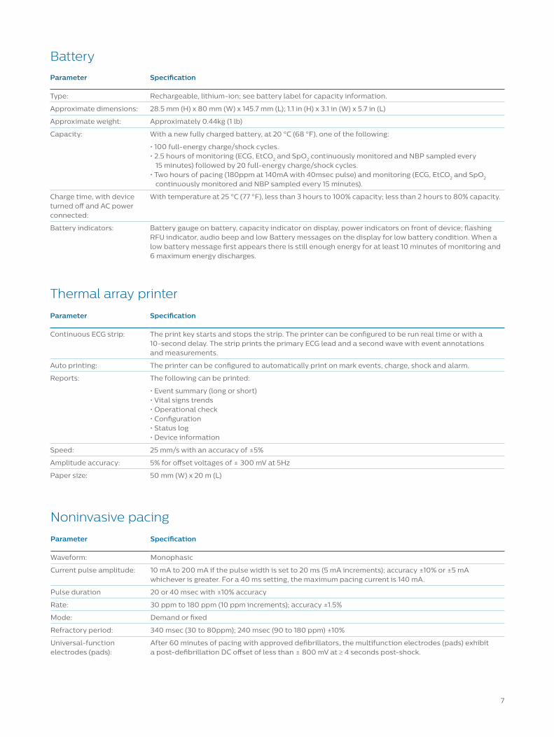
Parameter Specification
Type: Rechargeable, lithium-ion; see battery label for capacity information.
Approximate dimensions: 28.5 mm (H) x 80 mm (W) x 145.7 mm (L); 1.1 in (H) x 3.1 in (W) x 5.7 in (L)
Approximate weight: Approximately 0.44kg (1 lb)
Capacity: With a new fully charged battery, at 20 °C (68 °F), one of the following:
• 100 full-energy charge/shock cycles.• 2.5 hours of monitoring (ECG, EtCO2 and SpO2 continuously monitored and NBP sampled every 15 minutes) followed by 20 full-energy charge/shock cycles.• Two hours of pacing (180ppm at 140mA with 40msec pulse) and monitoring (ECG, EtCO2 and SpO2 continuously monitored and NBP sampled every 15 minutes).
Charge time, with device turned off and AC power connected:
With temperature at 25 °C (77 °F), less than 3 hours to 100% capacity; less than 2 hours to 80% capacity.
Battery indicators: Battery gauge on battery, capacity indicator on display, power indicators on front of device; flashing RFU indicator, audio beep and low Battery messages on the display for low battery condition. When a low battery message first appears there is still enough energy for at least 10 minutes of monitoring and 6 maximum energy discharges.
Parameter Specification
Continuous ECG strip: The print key starts and stops the strip. The printer can be configured to be run real time or with a 10-second delay. The strip prints the primary ECG lead and a second wave with event annotations and measurements.
Auto printing: The printer can be configured to automatically print on mark events, charge, shock and alarm.
Reports: The following can be printed:
• Event summary (long or short)• Vital signs trends• Operational check• Configuration• Status log• Device information
Speed: 25 mm/s with an accuracy of ±5%
Amplitude accuracy: 5% for offset voltages of ± 300 mV at 5Hz
Paper size: 50 mm (W) x 20 m (L)
Battery
Thermal array printer
Parameter Specification
Waveform: Monophasic
Current pulse amplitude: 10 mA to 200 mA if the pulse width is set to 20 ms (5 mA increments); accuracy ±10% or ±5 mA whichever is greater. For a 40 ms setting, the maximum pacing current is 140 mA.
Pulse duration 20 or 40 msec with ±10% accuracy
Rate: 30 ppm to 180 ppm (10 ppm increments); accuracy ±1.5%
Mode: Demand or fixed
Refractory period: 340 msec (30 to 80ppm); 240 msec (90 to 180 ppm) ±10%
Universal-function electrodes (pads):
After 60 minutes of pacing with approved defibrillators, the multifunction electrodes (pads) exhibit a post-defibrillation DC offset of less than ± 800 mV at ≥ 4 seconds post-shock.
Noninvasive pacing
7
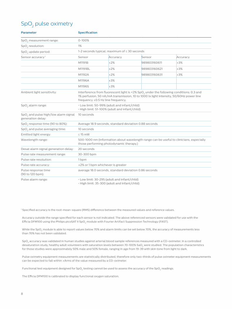
Parameter Specification
SpO2 measurement range: 0-100%
SpO2 resolution: 1%
SpO2 update period: 1-2 seconds typical; maximum of ≤ 30 seconds
Sensor accuracy 1 Sensor Accuracy Sensor Accuracy
M1191B ±2% 989803160611 ±3%
M1191BL ±2% 989803160621 ±3%
M1192A ±2% 989803160631 ±3%
M1196A ±3%
M1196S ±3%
Ambient light sensitivity: Interference from fluorescent light is <2% SpO2 under the following conditions: 0.3 and 1% perfusion, 50 nA/mA transmission, 10 to 1000 lx light intensity, 50/60Hz power line frequency ±0.5 Hz line frequency.
SpO2 alarm range: • Low limit: 50-99% (adult and infant/child)• High limit: 51-100% (adult and infant/child)
SpO2 and pulse high/low alarm signal generation delay:
10 seconds
SpO2 response time (90 to 80%): Average 18.9 seconds, standard deviation 0.88 seconds
SpO2 and pulse averaging time: 10 seconds
Emitted light energy: ≤ 15 mW
Wavelength range: 500-1000 nm (information about wavelength range can be useful to clinicians, especially those performing photodynamic therapy.)
Desat alarm signal generation delay: 20 seconds
Pulse rate measurement range: 30-300 bpm
Pulse rate resolution: 1 bpm
Pulse rate accuracy: ±2% or 1 bpm whichever is greater
Pulse response time (90 to 120 bpm):
average 18.0 seconds, standard deviation 0.86 seconds
Pulse alarm range: • Low limit: 30-295 (adult and infant/child)• High limit: 35-300 (adult and infant/child)
SpO2 pulse oximetry
1 Specified accuracy is the root-mean-square (RMS) difference between the measured values and reference values. Accuracy outside the range specified for each sensor is not indicated. The above referenced sensors were validated for use with the Efficia DFM100 using the Philips picoSAT II SpO2 module with Fourier Artifact Suppression Technology (FAST).
While the SpO2 module is able to report values below 70% and alarm limits can be set below 70%, the accuracy of measurements less than 70% has not been validated.
SpO2 accuracy was validated in human studies against arterial blood sample references measured with a CO-oximeter. In a controlled desaturation study, healthy adult volunteers with saturation levels between 70-100% SaO2 were studied. The population characteristics for those studies were approximately 50% male and 50% female, ranging in age from 19-39 with skin tone from light to dark.
Pulse oximetry equipment measurements are statistically distributed, therefore only two-thirds of pulse oximeter equipment measurements can be expected to fall within ±Arms of the value measured by a CO-oximeter.
Functional test equipment designed for SpO2 testing cannot be used to assess the accuracy of the SpO2 readings.
The Efficia DFM100 is calibrated to display functional oxygen saturation.
8

Parameter Specification
Weight: Mainstream: 78 g (2.75 oz.); Sidestream: 272 g (9.6 oz.)
Dimensions: Mainstream: 43 mm (W) x 33 mm (H) x 23 mm (L); 1.69 in (W) x 1.29 (H) x .90 in (L); Sidestream: 66 mm (W) x 38 mm (H) x 89 mm (L); 2.6 in (W) x 1.5 in (H) x 3.5 in (L)
Range: 0-150 mmHg
Resolution: 1 mmHg (0.1 kPa)
Accuracy: 0 - 40 mmHg ± 2 mmHg; 41 - 70 mmHg ± 5% of reading; 71 - 100 mmHg ± 8% of reading; 101 - 150 mmHg ± 10 % of reading. Gas at 25°C.
Drift of measurement accuracy:
Over any 24 hour period, the specified measurement accuracy is maintained.
Warm-up time 2 minutes at 25°C.
System response time: Sidestream: 3.5 seconds typical.
Alarm delay time: (after alarm condition has been met) Mainstream – less than 5 seconds; Sidestream – less than 8 seconds; Measurement method: peak EtCO2 value within a 10-second window.
Sample flow rate: Sidestream - 50 ml/minute ±10ml
Alarm range: • Low limit: 10-140 mmHg (adult, infant/child)• High limit: 20-145 mmHg (adult, infant/child)
Parameter Specification
Range: 0-150 rpm
Resolution: 1 rpm
Accuracy: ±1 rpm
Alarm range: • Low limit: 0-99 rpm (adult, infant/child)• High limit: 10-100 rpm (adult, infant/child)
Alarm delay time: (after alarm condition has been met) Mainstream - less than 5 seconds; Sidestream – less than 8 seconds; measurement method: AwRR - based on the last 8 detected breaths; apnea – Following the configured apnea delay time.
EtCO2
AwRR
Parameter Specification
Pressure range: Measurement mmHg kPa
Adult Infant/Child Adult Infant/Child
Systolic 30-255 30-135 4-34 4-18
Diastolic 10-220 10-110 1.3-29.3 1.3-14.7
Mean 20-235 20-125 2.7-31.3 2.7-16.7
Initial pressure: 160 mmHg/21.3 kPa for adults120 mmHg/16 kPa for infant/child
Maximum pressure: 300 mmHg/40 kPa
Overpressure safety limits: 290 mmHg/38.6 kPa
Cuff inflation time: 75 seconds maximum
Pressure transducer accuracy: ±3 mmHg over the range 0-300 mmHg/0-40 kPa
NBP
9
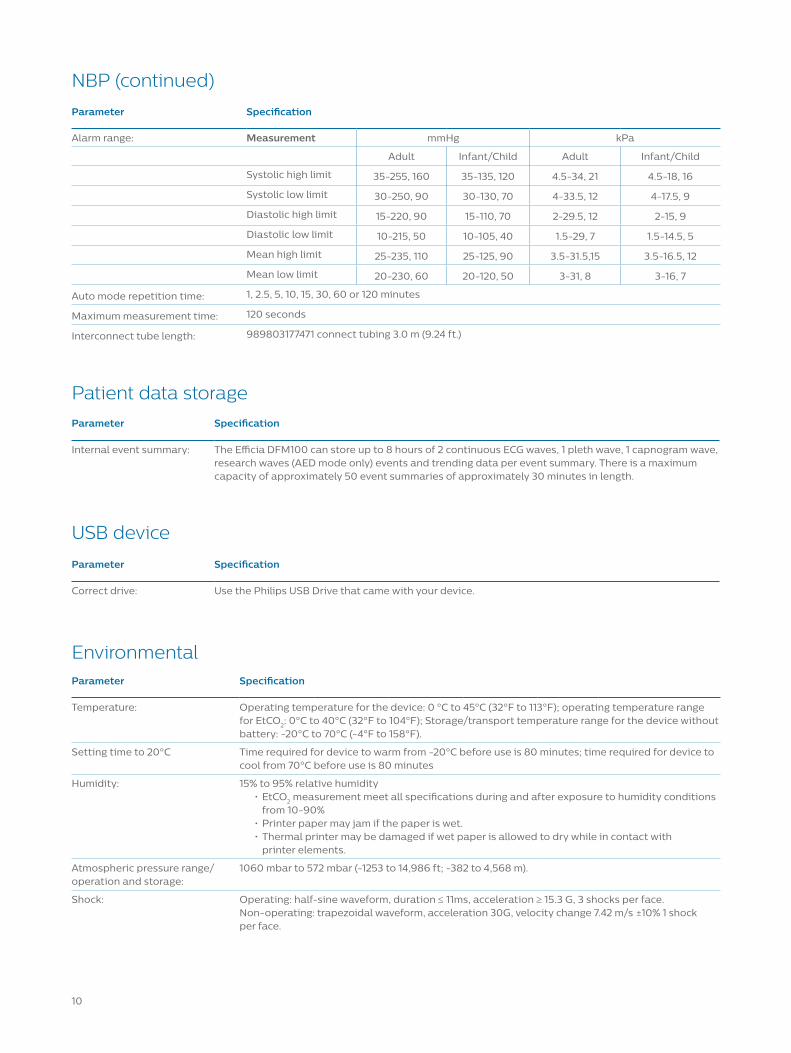
Parameter Specification
Alarm range: Measurement mmHg kPa
Adult Infant/Child Adult Infant/Child
Systolic high limit 35-255, 160 35-135, 120 4.5-34, 21 4.5-18, 16
Systolic low limit 30-250, 90 30-130, 70 4-33.5, 12 4-17.5, 9
Diastolic high limit 15-220, 90 15-110, 70 2-29.5, 12 2-15, 9
Diastolic low limit 10-215, 50 10-105, 40 1.5-29, 7 1.5-14.5, 5
Mean high limit 25-235, 110 25-125, 90 3.5-31.5,15 3.5-16.5, 12
Mean low limit 20-230, 60 20-120, 50 3-31, 8 3-16, 7
Auto mode repetition time: 1, 2.5, 5, 10, 15, 30, 60 or 120 minutes
Maximum measurement time: 120 seconds
Interconnect tube length: 989803177471 connect tubing 3.0 m (9.24 ft.)
NBP (continued)
Parameter Specification
Temperature: Operating temperature for the device: 0 °C to 45°C (32°F to 113°F); operating temperature range for EtCO2: 0°C to 40°C (32°F to 104°F); Storage/transport temperature range for the device without battery: -20°C to 70°C (-4°F to 158°F).
Setting time to 20°C Time required for device to warm from -20°C before use is 80 minutes; time required for device to cool from 70°C before use is 80 minutes
Humidity: 15% to 95% relative humidity• EtCO2 measurement meet all specifications during and after exposure to humidity conditions
from 10-90%• Printer paper may jam if the paper is wet.• Thermal printer may be damaged if wet paper is allowed to dry while in contact with
printer elements.
Atmospheric pressure range/ operation and storage:
1060 mbar to 572 mbar (-1253 to 14,986 ft; -382 to 4,568 m).
Shock: Operating: half-sine waveform, duration ≤ 11ms, acceleration ≥ 15.3 G, 3 shocks per face.Non-operating: trapezoidal waveform, acceleration 30G, velocity change 7.42 m/s ±10% 1 shock per face.
Environmental
Parameter Specification
Internal event summary: The Efficia DFM100 can store up to 8 hours of 2 continuous ECG waves, 1 pleth wave, 1 capnogram wave, research waves (AED mode only) events and trending data per event summary. There is a maximum capacity of approximately 50 event summaries of approximately 30 minutes in length.
Patient data storage
Parameter Specification
Correct drive: Use the Philips USB Drive that came with your device.
USB device
10
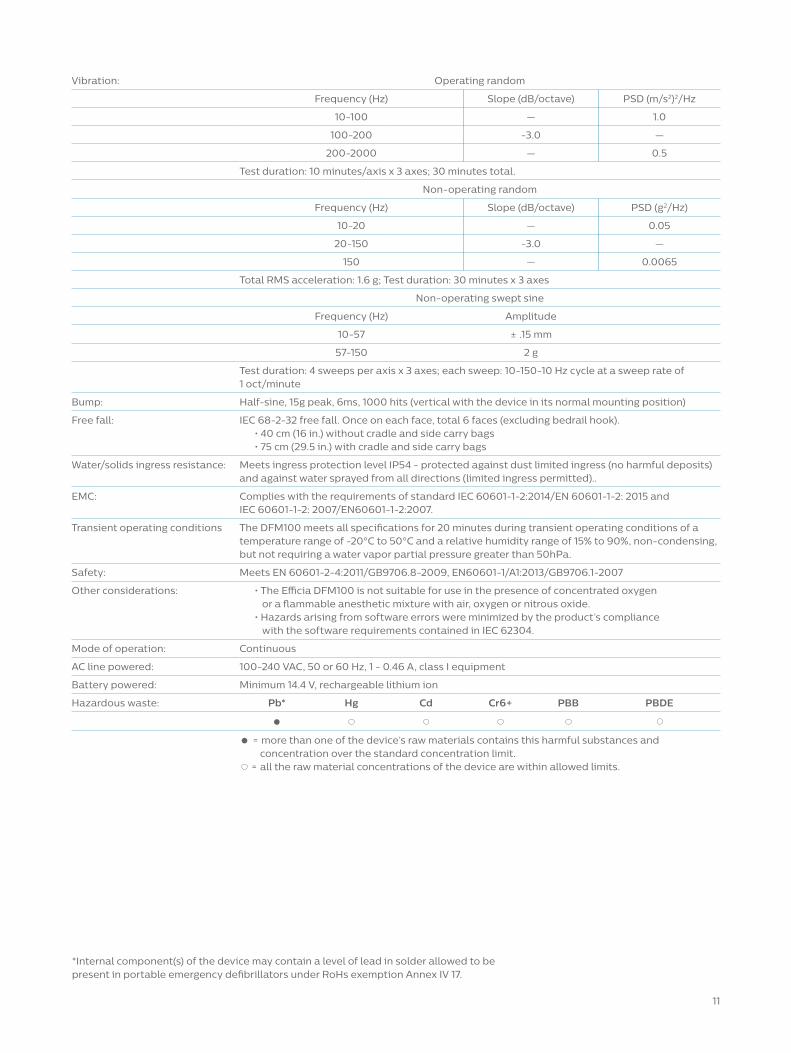
Vibration: Operating random
Frequency (Hz) Slope (dB/octave) PSD (m/s2)2/Hz
10-100 — 1.0
100-200 -3.0 —
200-2000 — 0.5
Test duration: 10 minutes/axis x 3 axes; 30 minutes total.
Non-operating random
Frequency (Hz) Slope (dB/octave) PSD (g2/Hz)
10-20 — 0.05
20-150 -3.0 —
150 — 0.0065
Total RMS acceleration: 1.6 g; Test duration: 30 minutes x 3 axes
Non-operating swept sine
Frequency (Hz) Amplitude
10-57 ± .15 mm
57-150 2 g
Test duration: 4 sweeps per axis x 3 axes; each sweep: 10-150-10 Hz cycle at a sweep rate of 1 oct/minute
Bump: Half-sine, 15g peak, 6ms, 1000 hits (vertical with the device in its normal mounting position)
Free fall: IEC 68-2-32 free fall. Once on each face, total 6 faces (excluding bedrail hook).• 40 cm (16 in.) without cradle and side carry bags• 75 cm (29.5 in.) with cradle and side carry bags
Water/solids ingress resistance: Meets ingress protection level IP54 - protected against dust limited ingress (no harmful deposits) and against water sprayed from all directions (limited ingress permitted)..
EMC: Complies with the requirements of standard IEC 60601-1-2:2014/EN 60601-1-2: 2015 andIEC 60601-1-2: 2007/EN60601-1-2:2007.
Transient operating conditions The DFM100 meets all specifications for 20 minutes during transient operating conditions of a temperature range of -20°C to 50°C and a relative humidity range of 15% to 90%, non-condensing, but not requiring a water vapor partial pressure greater than 50hPa.
Safety: Meets EN 60601-2-4:2011/GB9706.8-2009, EN60601-1/A1:2013/GB9706.1-2007
Other considerations: • The Efficia DFM100 is not suitable for use in the presence of concentrated oxygen or a flammable anesthetic mixture with air, oxygen or nitrous oxide.
• Hazards arising from software errors were minimized by the product’s compliance with the software requirements contained in IEC 62304.
Mode of operation: Continuous
AC line powered: 100-240 VAC, 50 or 60 Hz, 1 - 0.46 A, class I equipment
Battery powered: Minimum 14.4 V, rechargeable lithium ion
Hazardous waste: Pb* Hg Cd Cr6+ PBB PBDE
=
= = more than one of the device’s raw materials contains this harmful substances and concentration over the standard concentration limit. = all the raw material concentrations of the device are within allowed limits.
11
*Internal component(s) of the device may contain a level of lead in solder allowed to be present in portable emergency defibrillators under RoHs exemption Annex IV 17.
Electromagnetic Capability
Reducing Electromagnetic Interference
When using the Efficia DFM100, electromagnetic compatibility with surrounding devices should be assessed.
A medical device can either generate or receive electromagnetic disturbances. Testing for electromagnetic compatibility EMC with the appropriate accessories has been performed according to national and international standard for EMC for medical devices.
The EMC standards describe tests for both emitted and received disturbances. Emission tests deal with electromagnetic disturbances generated by the device being tested.
WARNINGS: Electromagnetic interference coming from other devices may degrade or obstruct the performance of the Efficia DFM100. The interference may come from signals radiated through the air or it may also come from signals conducted through wired connections such as power cord, patient connections or device to device connections such as ECG analog output. Electromagnetic compatibility with surrounding devices should be assessed prior to using the Efficia DFM100.
When connected to a patient, symptoms of interference may include degraded performance of ECG signals from pads/paddles or ECG leadsets, unexpected technical alarms, or critical failure status on the RFU Indicator. Electromagnetic compatibility testing should include both radiated and conducted immunity. Testing in the presence of potentially interfering surrounding devices should assess typical Efficia DFM100 usage scenarios including powering on, monitoring and delivering therapy.
Fixed, portable, and mobile radio frequency communications equipment could affect the performance of medical equipment.
The Efficia DFM100 and associated accessories may be susceptible to interference from other RF energy sources and continuous, repetitive, power line bursts. Examples of other sources of RF interference are medical devices, cellular products, information technology equipment and radio/television transmission. Should interference be encountered, as demonstrated by error conditions, artifact on the ECG or dramatic variations in parameter measurement values, attempt to locate the source. Assess:
Is the interference intermittent or constant?
• Does the interference occur only in certain locations?• Does the interference occur only when in close proximity to certain medical devices?• Does the interference occur only when certain medical devices are turned on?• Does the interference occur only when certain medical devices are connected to the same patient as the Efficia DFM100?• Do parameter measurement values change dramatically when the AC line cord is unplugged?
Once the source is located, attempt to attenuate the EMC coupling path by distancing the monitor/defibrillator from the source as much as possible or by changing the location or routing of wired connections. If assistance is needed, call your local service representative.
Essential Performance DeterminationsThe following Essential Performance of the Efficia DFM100 was determined from the product’s Safety Risk Assessment. This performance was maintained during EMC evaluation testing and disturbances per IEC 60601-1-2 and includes:
• The ability to deliver defibrillation therapy (manual, AED and synchronized cardioversion).• The ability to deliver pacing therapy (fixed and demand).• The ability to monitor the patient parameters (ECG monitoring, pulse oximetry, end-tidal CO2, non-invasive blood pressure).• The ability to detect and generate physiological alarms.
Restrictions for UseArtifact on the ECG and parameter waveforms caused by electromagnetic disturbances should be evaluated by a physician or physician-authorized personnel to determine if it will negatively impact patient diagnosis or treatment.
12
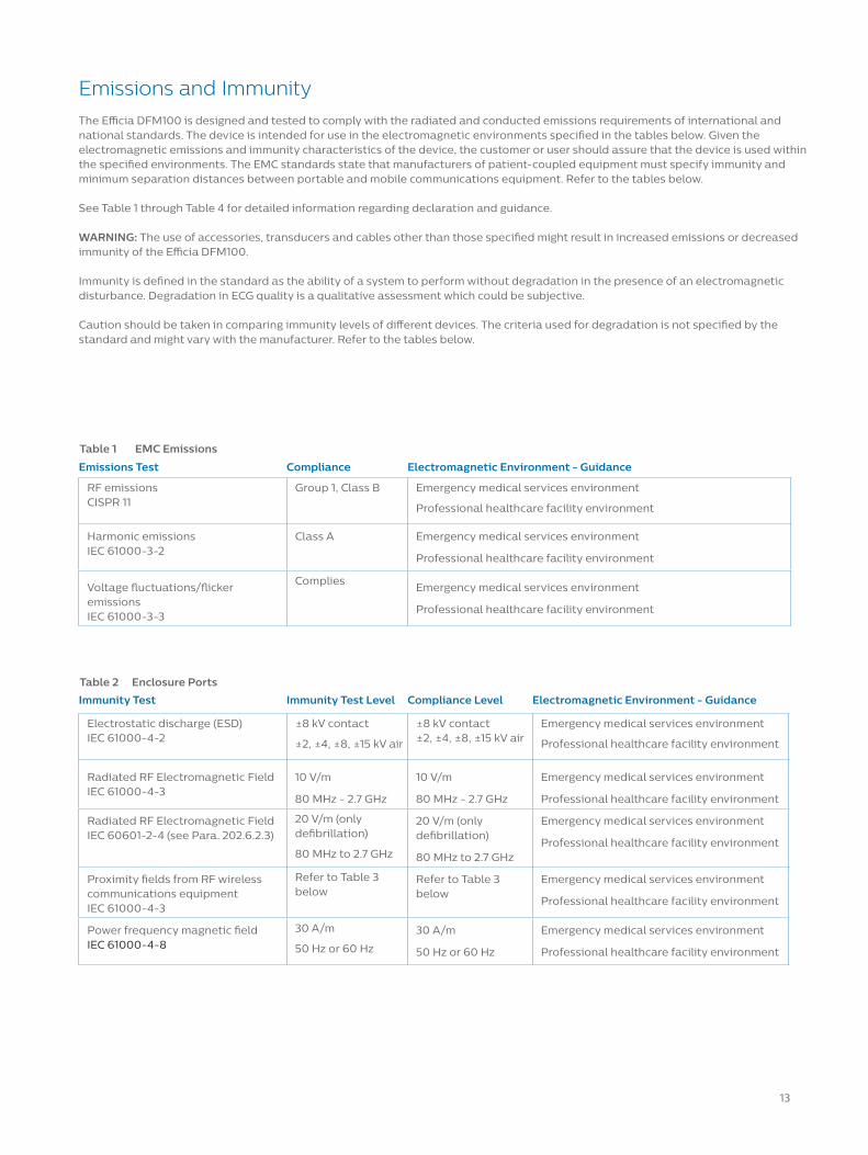
Emissions and Immunity
The Efficia DFM100 is designed and tested to comply with the radiated and conducted emissions requirements of international and national standards. The device is intended for use in the electromagnetic environments specified in the tables below. Given the electromagnetic emissions and immunity characteristics of the device, the customer or user should assure that the device is used within the specified environments. The EMC standards state that manufacturers of patient-coupled equipment must specify immunity and minimum separation distances between portable and mobile communications equipment. Refer to the tables below.
See Table 1 through Table 4 for detailed information regarding declaration and guidance.
WARNING: The use of accessories, transducers and cables other than those specified might result in increased emissions or decreased immunity of the Efficia DFM100.
Immunity is defined in the standard as the ability of a system to perform without degradation in the presence of an electromagnetic disturbance. Degradation in ECG quality is a qualitative assessment which could be subjective.
Caution should be taken in comparing immunity levels of different devices. The criteria used for degradation is not specified by the standard and might vary with the manufacturer. Refer to the tables below.
Emissions Test Compliance Electromagnetic Environment - Guidance
RF emissions CISPR 11
Group 1, Class B Emergency medical services environment
Professional healthcare facility environment
Harmonic emissions IEC 61000-3-2
Class A Emergency medical services environment
Professional healthcare facility environment
Voltage fluctuations/flicker emissions IEC 61000-3-3
Complies Emergency medical services environment
Professional healthcare facility environment
Table 1 EMC Emissions
Immunity Test Immunity Test Level Compliance Level Electromagnetic Environment - Guidance
Electrostatic discharge (ESD) IEC 61000-4-2
±8 kV contact
±2, ±4, ±8, ±15 kV air
±8 kV contact ±2, ±4, ±8, ±15 kV air
Emergency medical services environment
Professional healthcare facility environment
Radiated RF Electromagnetic FieldIEC 61000-4-3
10 V/m
80 MHz - 2.7 GHz
10 V/m
80 MHz - 2.7 GHz
Emergency medical services environment
Professional healthcare facility environment
Radiated RF Electromagnetic Field IEC 60601-2-4 (see Para. 202.6.2.3)
20 V/m (only defibrillation)
80 MHz to 2.7 GHz
20 V/m (only defibrillation)
80 MHz to 2.7 GHz
Emergency medical services environment
Professional healthcare facility environment
Proximity fields from RF wireless communications equipmentIEC 61000-4-3
Refer to Table 3 below
Refer to Table 3 below
Emergency medical services environment
Professional healthcare facility environment
Power frequency magnetic fieldIEC 61000-4-8
30 A/m
50 Hz or 60 Hz
30 A/m
50 Hz or 60 Hz
Emergency medical services environment
Professional healthcare facility environment
Table 2 Enclosure Ports
13

Test Frequency (MHz)
Band a)(MHz)
Serivce a) Modulation b) Modulation b)(W)
Distance (m) Immunity Level (V/m)
385 380-390 TETRA 400 Pulse modulation18Hz
1.8 0.3 27
450 430-470 GMRS 460,FRS 460
FM± 5 kHzdeviation1 kHz sine
2 0.3 28
710745780
704-787 LTE Band 13,17
Pulse modulation217 Hz
0.2 0.3 9
810870930
800-960 GSM 800/900,TETRA 800,iDEN 820,CDMA 850,LTE Band 5
Pulse modulation18 Hz
2 0.3 28
172018451970
1700-1990 GSM 1800;CDMA 1900;GSM 1900;DECT; LTEBand 1, 3, 4, 25; UMTS
Pulse modulation217 Hz
2 0.3 28
2450 2400-2570 Bluetooth, WLAN, 802.11 b/g/n, RFID 2450, LTE Band 7
Pulse modulation217 Hz
2 0.3 28
524055005785
5100-5800 WLAN802.11 a/n
Pulse modulation217 Hz
0.2 0.3 9
Table 3 Proximity Fields from RF Wireless Communications
Immunity Test Immunity Test Level Compliance Level Electromagnetic Environment - Guidance
Electrical fast transient/burstIEC 61000-4-4
±2 kV ±2 kV Emergency medical services environment
Professional healthcare facility environment
Surge Line to line IEC 61000-4-5
±0.5 kV, ±1 kV ±0.5 kV, ±1 kV Emergency medical services environment
Professional healthcare facility environment
Surge Line to ground IEC 61000-4-5
±0.5 kV, ±1 kV, ±2 kV ±0.5 kV, ±1 kV, ±2 kV Emergency medical services environment
Professional healthcare facility environment
Conducted disturbances induced by RF fields
3 V
0.15 MHz - 80 MHz
6 V in ISM and amateur radio bands between 0.15 MHz and 80 MHz
3 V
0.15 MHz - 80 MHz
6 V in ISM and amateur radio bands between 0.15 MHz and 80 MHz
Emergency medical services environment
Professional healthcare facility environment
Voltage dips, short interruptions, and voltage variations on power supply input linesIEC 61000-4-11
0% UT; 0,5 cycle
At 0°, 45°, 90°, 135°, 180°, 225°, 270°, and 315°
0% UT; 1 cycle and 70% UT; 25/30 cycles
Single phase: at 0°
0% UT; 0,5 cycle
At 0°, 45°, 90°, 135°, 180°, 225°, 270°, and 315°
0% UT; 1 cycle and 70% UT; 25/30 cycles
Single phase: at 0°
Emergency medical services environment
Professional healthcare facility environment
Voltage interruptions IEC 61000-4-11
0% UT; 250/300 cycle 0% UT; 250/300 cycle Emergency medical services environment
Professional healthcare facility environment
Table 4 Input AC Power Ports
WARNING: The use of portable and mobile radio communications equipment can affect the operation of this device. Keep all portable and mobile radio communications equipment at a minimum distance of 30 cm (12 inches) from any part of the Efficia DFM100.
14

Immunity Test Immunity Test Level Compliance Level Electromagnetic Environment - Guidance
Electrostatic discharge (ESD)IEC 61000-4-2
±8 kV contact
±2, ±4, ±8, ±15 kV air
±8 kV contact
±2, ±4, ±8, ±15 kV air
Emergency medical services environment
Professional healthcare facility environment
Electrical fast transient/burstIEC 61000-4-4
±1 kV ±1 kV Emergency medical services environment
Professional healthcare facility environment
Conducted disturbances induced by RF fieldsIEC 61000-4-6
3 V
0.15 MHz - 80 MHz
6 V in ISM and amateur radio bands between 0.15 MHz and 80 MHz
3 V
0.15 MHz - 80 MHz
6 V in ISM and amateur radio bands between 0.15 MHz and 80 MHz
Emergency medical services environment
Professional healthcare facility environment
Table 5 Signal Input/Output Ports
Immunity Test Immunity Test Level Compliance Level Electromagnetic Environment - Guidance
Electrostatic discharge (ESD)IEC 61000-4-2
±8 kV contact
±2, ±4, ±8, ±15 kV air
±8 kV contact
±2, ±4, ±8, ±15 kV air
Emergency medical services environment
Professional healthcare facility environment
Conducted disturbances induced by RF fieldsIEC 61000-4-6
3 V
0.15 MHz - 80 MHz
6 V in ISM and amateur radio bands between 0.15 MHz and 80 MHz
3 V
0.15 MHz - 80 MHz
6 V in ISM and amateur radio bands between 0.15 MHz and 80 MHz
Emergency medical services environment
Professional healthcare facility environment
Table 6 Patient Coupling Ports
The EMC standards state that manufacturers of medical equipment must specify the maximum lengths of any associated cables that are likely to affect the compliance of the device with emission and immunity tests. The following table lists the maximum lengths of these cables.
Part Number Maximum Cable Length Description
3-Lead ECG Cable Set
M1669A 2.7 m 3-Lead Trunk Cable, AAMI/IEC
M1674A 1.0 m 3-Lead ICU Snap, IEC
M1678A 1.0 m 3-Leadset OR Grabber, IEC
M1672A1.0 m 3-Leadset ICU Grabber, IEC
M1673A 1.0 m 3-Leadset ICU Snap, AAMI
M1671A 1.0 m 3-Leadset ICU Grabber, AAMI
989803160641 2.7 m Efficia 3/5 ECG Trunk Cable, AAMI/IEC
989803160651 1.0 m Efficia 3-Lead Grabber, AAMI
989803160661 1.0 m Efficia 3-Lead Grabber, IEC
989803160671 1.0 m Efficia 3-Lead Snap, AAMI
989803160681 1.0 m Efficia 3-Lead Snap, IEC
989803170171 2.7 m OR 3-Lead ECG Trunk Cable, AAMI/IEC
Table 6 Applicable Cables with Maximum Lengths
15

Part Number Maximum Cable Length Description
5-Lead ECG Cable Set
M1645A 1.6 m 5-Lead ICU Snap, IEC
M1668A 2.7 m 5-Lead ECG Trunk Cable, AAMI/IEC
M1971A 1.6 m 5-Leadset, ICU Grabber, IEC
M1974A 1.6 m 5-Leadset, OR Grabber, IEC
M1644A 1.6 m 5-Leadset, ICU Snap Limb, AAMI
M1968A 1.6 m 5-Leadset, ICU Grabber Limb, AAMI
989803160691 1.6 m Efficia 5-Lead Grabber Limb, AAMI
9898031607011.6 m Efficia 5-Lead Grabber Limb, IEC
989803160711 1.6 m Efficia 5-Lead Snap Limb, AAMI
989803160721 1.6 m Efficia 5-Lead Snap Limb, IEC
989803170181 2.7 m OR 5-Lead ECG Trunk Cable, AAMI/IEC
989803176161 1.6 m 5-Lead Snap Limb, Shielded, AAMI
989803176181 1.6 m 5-Lead Snap Limb, Shielded, IEC
Internal Paddles
M4741A 3.9 m 7.5 cm Switched Internal Paddles
M4742A3.9 m 6.0 cm Switched Internal Paddles
M4743A 3.9 m 4.5 cm Switched Internal Paddles
M1741A 3.9 m 7.5 cm Internal Paddles
M1742A 3.9 m 6.0 cm Internal Paddles
M1743A 3.9 m 4.5 cm Internal Paddles
M4740A 0.3 m Internal Paddles Adapter Cable
External Paddles
M3543A4.8 m External Paddles - Water Resistant
989803196431 4.8 m Efficia External Paddles with PCI - Water Resistant
Hands-free Pads Therapy Cables
M3507A 2.2 m Hands-free Cable Barrel Connector
M3508A 2.2 m HeartStart Hands-free Cable
989803197111 2.1 m DFM100 Pads Cable
Multifunction Defibrillator Pads - Barrel Connector
M3501A0.6 m Adult/Child Multifunction Defibrillation Electrode Pads (10 sets)
M3504A 0.6 m Infant Multifunction Defibrillation Electrode Pads (<10 kg) (5 sets)
Table 6 Applicable Cables with Maximum Lengths (Continued)
16
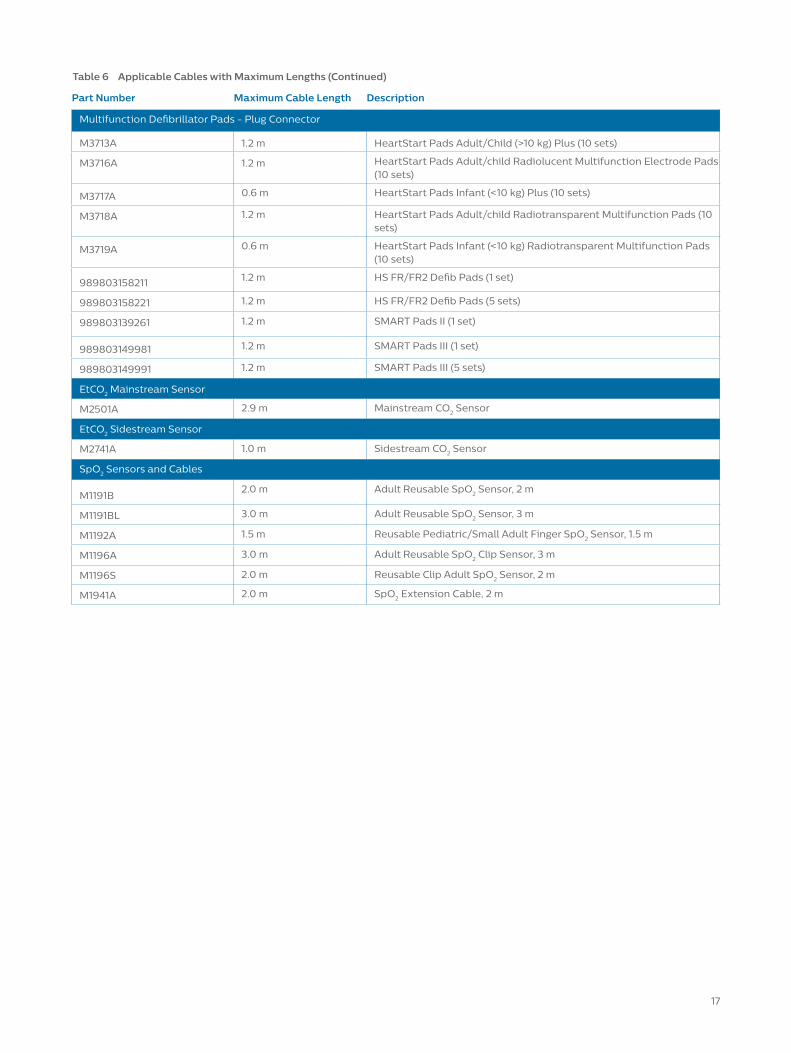
Part Number Maximum Cable Length Description
Multifunction Defibrillator Pads - Plug Connector
M3713A 1.2 m HeartStart Pads Adult/Child (>10 kg) Plus (10 sets)
M3716A 1.2 m HeartStart Pads Adult/child Radiolucent Multifunction Electrode Pads (10 sets)
M3717A 0.6 m HeartStart Pads Infant (<10 kg) Plus (10 sets)
M3718A 1.2 m HeartStart Pads Adult/child Radiotransparent Multifunction Pads (10 sets)
M3719A 0.6 m HeartStart Pads Infant (<10 kg) Radiotransparent Multifunction Pads (10 sets)
989803158211 1.2 m HS FR/FR2 Defib Pads (1 set)
989803158221 1.2 m HS FR/FR2 Defib Pads (5 sets)
989803139261 1.2 m SMART Pads II (1 set)
989803149981 1.2 m SMART Pads III (1 set)
989803149991 1.2 m SMART Pads III (5 sets)
EtCO2 Mainstream Sensor
M2501A 2.9 m Mainstream CO2 Sensor
EtCO2 Sidestream Sensor
M2741A 1.0 m Sidestream CO2 Sensor
SpO2 Sensors and Cables
M1191B2.0 m Adult Reusable SpO2 Sensor, 2 m
M1191BL 3.0 m Adult Reusable SpO2 Sensor, 3 m
M1192A 1.5 m Reusable Pediatric/Small Adult Finger SpO2 Sensor, 1.5 m
M1196A 3.0 m Adult Reusable SpO2 Clip Sensor, 3 m
M1196S 2.0 m Reusable Clip Adult SpO2 Sensor, 2 m
M1941A 2.0 m SpO2 Extension Cable, 2 m
Table 6 Applicable Cables with Maximum Lengths (Continued)
17
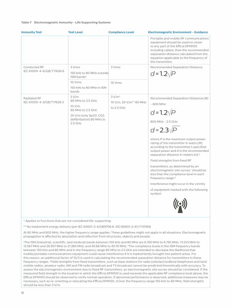
Table 7 Electromagnetic Immunity - Life Supporting Systems
Immunity Test Test Level Compliance Level Electromagnetic Environment - Guidance
Portable and mobile RF communications equipment should be used no closer to any part of the Efficia DFM100 including cables, than the recommended separation distance calculated from the equation applicable to the frequency of the transmitter.
Conducted RFIEC 61000-4-6/GB/T17626.6
3 Vrms
150 kHz to 80 MHz outside ISM bandsa
3 Vrms Recommended Separation Distance:
10 Vrms
150 kHz to 80 MHz in ISM bands
10 Vrms
Radiated RFIEC 61000-4-3/GB/T17626.3
3 V/m 80 MHz to 2.5 GHz
10 V/m 80 MHz to 2.5 GHz
20 V/m (only SpO2, CO2, defibrillation) 80 MHz to 2.5 GHz
3 V/m*
10 V/m, 20 V/m** 80 MHz
to 2.5 GHz
Recommended Separation Distances 80
- 800 MHz:
800 MHz - 2.5 GHz:
where P is the maximum output power rating of the transmitter in watts (W) according to the transmitter’s specified output power and d is the recommended separation distance in meters (m).b
Field strengths from fixed RF
transmitters, as determined by an electromagnetic site survey,c should be less than the compliance level in each frequency range.d
Interference might occur in the vicinity
of equipment marked with the following symbol:
* Applies to functions that are not considered life-supporting.
** No inadvertent energy delivery (per IEC 60601-2-4/GB9706.8, ISO 80601-2-61/YY0784)
At 80 MHz and 800 MHz, the higher frequency range applies. These guidelines might not apply in all situations. Electromagneticpropagation is affected by absorption and reflection from structures, objects and people.
aThe ISM (industrial, scientific, and medical) bands between 150 kHz and 80 MHz are 6.765 MHz to 6.795 MHz; 13.553 MHz to13.567 MHz and 26.957 MHz to 27.283 MHz; and 40.66 MHz to 40.70 MHz. bThe compliance levels in the ISM frequency bandsbetween 150 kHz and 80 MHz and in the frequency range 80 MHz to 2.5 GHz are intended to decrease the likelihood thatmobile/portable communications equipment could cause interference if it is inadvertently brought into patient areas. For this reason, an additional factor of 10/3 is used in calculating the recommended separation distance for transmitters in these frequency ranges. cField strengths from fixed transmitters, such as base stations for radio (cellular/cordless) telephones and land mobile radios, amateur radio, AM and FM radio broadcast and TV broadcast cannot be predicted theoretically with accuracy. To assess the electromagnetic environment due to fixed RF transmitters, an electromagnetic site survey should be considered. If the measured field strength in the location in which the Efficia DFM100 is used exceeds the applicable RF compliance level above, the Efficia DFM100 should be observed to verify normal operation. If abnormal performance is observed, additional measures may be necessary, such as re-orienting or relocating the Efficia DFM100. d Over the frequency range 150 kHz to 80 MHz, field strengths should be less than 3 V/m.
d = 1.2 P
d = 1.2 P
d = 2.3 P
18
Recommended Separation Distances
Rated MaximumOutput Power ofTransmitter (W)
150 kHZ to 800 MHz 800 MHz to 2.5 GHz
0.01 0.1 m 0.2 m
0.1 0.4 m 0.7 m
1 1.2 m 2.3 m
104 m 7 m
100 12 m 23 m
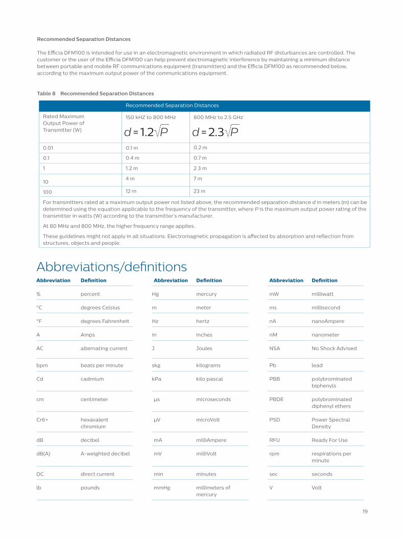
For transmitters rated at a maximum output power not listed above, the recommended separation distance d in meters (m) can be determined using the equation applicable to the frequency of the transmitter, where P is the maximum output power rating of the transmitter in watts (W) according to the transmitter’s manufacturer.
At 80 MHz and 800 MHz, the higher frequency range applies.
These guidelines might not apply in all situations. Electromagnetic propagation is affected by absorption and reflection from structures, objects and people.
Recommended Separation Distances
The Efficia DFM100 is intended for use in an electromagnetic environment in which radiated RF disturbances are controlled. The customer or the user of the Efficia DFM100 can help prevent electromagnetic interference by maintaining a minimum distance between portable and mobile RF communications equipment (transmitters) and the Efficia DFM100 as recommended below,according to the maximum output power of the communications equipment.
Table 8 Recommended Separation Distances
d = 1.2 P d = 2.3 P
19
Abbreviations/definitionsAbbreviation Definition Abbreviation Definition Abbreviation Definition
% percent Hg mercury mW milliwatt
°C degrees Celsius m meter ms millisecond
°F degrees Fahrenheit Hz hertz nA nanoAmpere
A Amps in inches nM nanometer
AC alternating current J Joules NSA No Shock Advised
bpm beats per minute skg kilograms Pb lead
Cd cadmium kPa kilo pascal PBB polybrominated biphenyls
cm centimeter µs microseconds PBDE polybrominated diphenyl ethers
Cr6+ hexavalent chromium
µV microVolt PSD Power Spectral Density
dB decibel mA milliAmpere RFU Ready For Use
dB(A) A-weighted decibel mV milliVolt rpm respirations per minute
DC direct current min minutes sec seconds
lb pounds mmHg millimeters of mercury
V Volt

© 2020 Koninklijke Philips N.V. All rights reserved.Specifications are subject to change without notice.
www.philips.com/[email protected]
Printed in the Netherlands4522 991 59511 * APR 2020