Embed Size (px)
Citation preview
Effects of Solidification Behavior during Filling on Surface Defectsof Aluminum Alloy Die Casting+
Yasushi Iwata, Shuxin Dong, Yoshio Sugiyama and Hiroaki Iwahori
Toyota Central R&D Labs., Inc., Nagakute 480-1192, Japan
Die castings are prone to contain considerable porosities due to the entrapment of air or gases in the molten metal during mold filling.Reducing the die filling velocity is effective for reducing the entrapment, but it increases surface defects, such as surface folds and cold shut ondie castings.
In this research, the solidification behavior of molten metal during mold filling was investigated by developing a highly sensitivethermosensor with a response time of 0.015 s that can correctly measure the temperature of flowing molten metal. The criterion for the formationof surface defects was further examined based on the solidification behavior of molten metal during mold filling.
It was found that the type of surface defects varies with the solidification manner of aluminum alloys. Surface fold defects occur on diecastings made of JIS AD12.1 alloy with skin-formation type solidification. The occurrence of surface folds can be predicted by the thickness ofthe solidified layer of the molten metal from the surface of cavity. The critical thickness for the formation of surface folds increases withincreasing casting pressure. On the other hand, cold shut defects occur on die castings made of JIS AC4C alloy with mushy-formation typesolidification. The molten metal temperature drops toward the tip of the molten metal flow. The occurrence of cold shut defects can be estimatedby the temperature of this molten metal flow tip at the time this flow converges with other flows. [doi:10.2320/matertrans.F-M2013819]
(Received April 16, 2013; Accepted July 3, 2013; Published August 23, 2013)
Keywords: alloy, aluminum, die casting, defects, surface folds, cold shut, solidification
1. Introduction
Die casting is being applied to the manufacturing processof an increasing number of components owing to thedistinguished productivity for castings of intricate shapes.However, metallic molds used for die casting are severelydamaged by heavy thermal loads associated with the injectionof molten metal at high temperature and high pressure (up to70MPa). A strong clamping force for the mold is required inorder to handle such high casting pressures. As such, largedie casting machines are required for large die castings,which increases production costs. Therefore, if defects thatarise from decreases in casting pressure are be controlled,decreasing the die casting pressure will be an effectivemethod of reducing production costs.15)
At the same time, gas porosities generally occur in diecastings from the entrapment of air and gases into the moltenmetal due to violent flow during high-velocity injection.68)
Extending the low-velocity injection time has been reportedto be an effective method of reducing the amount ofentrapped gases and air.6,8) However, a large temperaturedrop in the molten metal due to a long injection time givesrise to other defects, such as surface folds, cold shut, evenmisrun.9,10) Therefore, it is necessary to clarify the causes andconditions of surface defects in order to perform die castingunder optimal conditions.
Aluminum alloy die castings for silicon content lower thanthat of JIS AD12.1 aluminum alloy (referred to hereinafteras AD12.1 alloy) is also required due to the diversificationof needs with respect to the properties of die casts. Thesolidification type changes as the content of silicon decreases,and this change may affect the castability of the alloys.
In the present study, focusing on the solidificationbehaviors of molten metal in the mold during injection, the
surface qualities of die castings were examined in relationto the temperature of the molten metal in the mold and thesolidification type of alloys of different silicon contents undervarious injection conditions.
2. Experimental Method
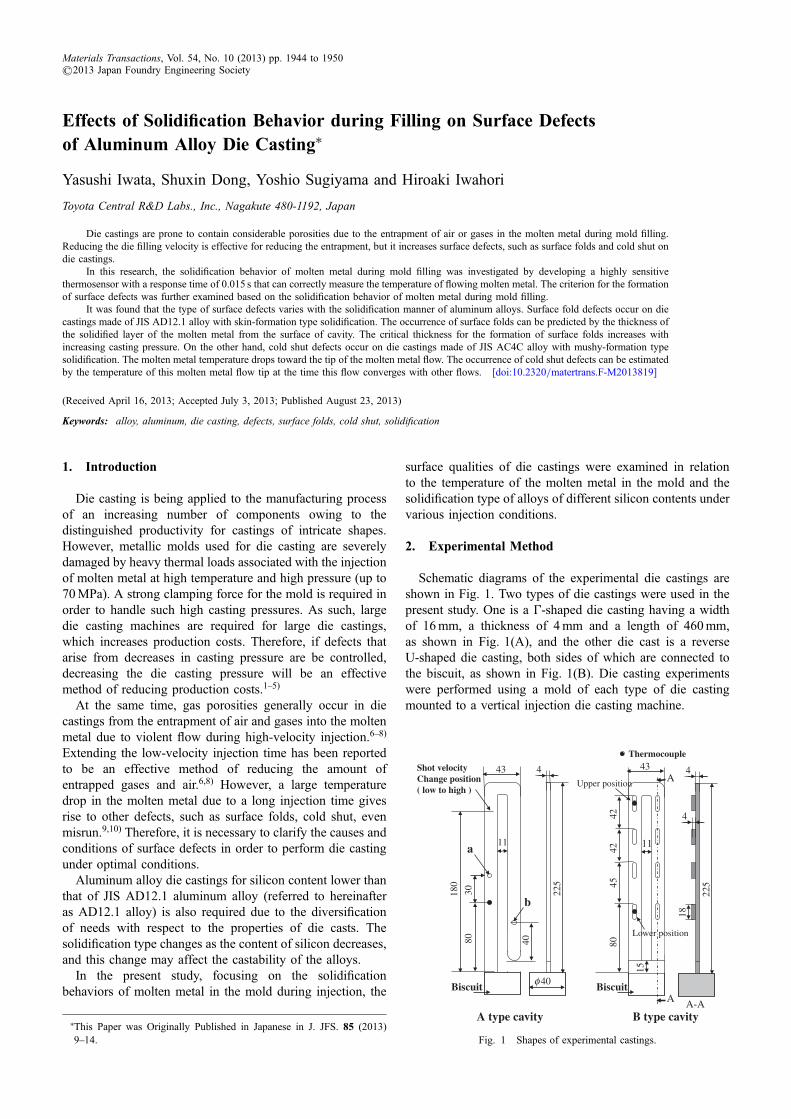
Schematic diagrams of the experimental die castings areshown in Fig. 1. Two types of die castings were used in thepresent study. One is a ¥-shaped die casting having a widthof 16mm, a thickness of 4mm and a length of 460mm,as shown in Fig. 1(A), and the other die cast is a reverseU-shaped die casting, both sides of which are connected tothe biscuit, as shown in Fig. 1(B). Die casting experimentswere performed using a mold of each type of die castingmounted to a vertical injection die casting machine.
Thermocouple
225
443
11
80
180
43
11
8042
4542
225
4
4
18
A
A A-A
15
Biscuit Biscuit
A type cavity B type cavity
φ 40
Shot velocity Change position( low to high )
30
40
a
b
Upper position
Lower position
Fig. 1 Shapes of experimental castings.
+This Paper was Originally Published in Japanese in J. JFS. 85 (2013)914.
Materials Transactions, Vol. 54, No. 10 (2013) pp. 1944 to 1950©2013 Japan Foundry Engineering Society
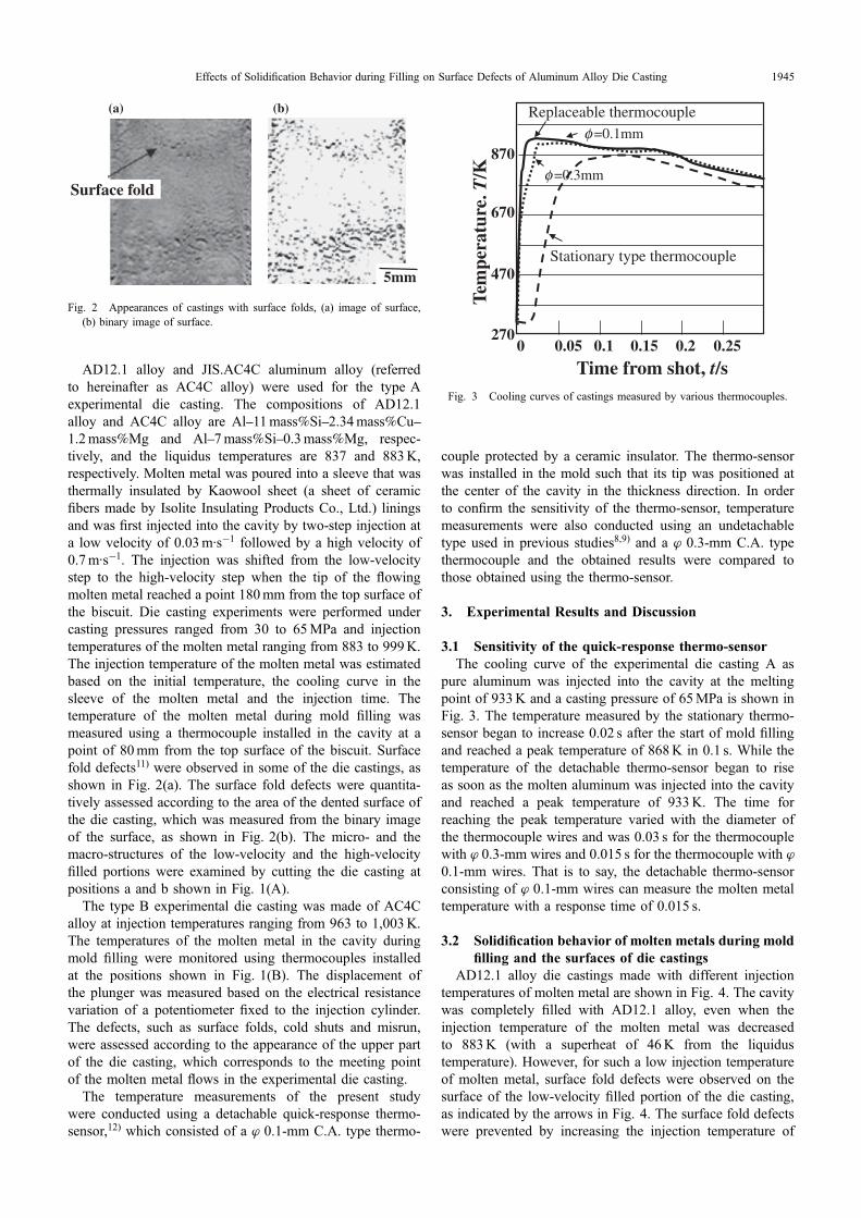
AD12.1 alloy and JIS.AC4C aluminum alloy (referredto hereinafter as AC4C alloy) were used for the type Aexperimental die casting. The compositions of AD12.1alloy and AC4C alloy are Al11mass%Si2.34mass%Cu1.2mass%Mg and Al7mass%Si0.3mass%Mg, respec-tively, and the liquidus temperatures are 837 and 883K,respectively. Molten metal was poured into a sleeve that wasthermally insulated by Kaowool sheet (a sheet of ceramicfibers made by Isolite Insulating Products Co., Ltd.) liningsand was first injected into the cavity by two-step injection ata low velocity of 0.03m·s¹1 followed by a high velocity of0.7m·s¹1. The injection was shifted from the low-velocitystep to the high-velocity step when the tip of the flowingmolten metal reached a point 180mm from the top surface ofthe biscuit. Die casting experiments were performed undercasting pressures ranged from 30 to 65MPa and injectiontemperatures of the molten metal ranging from 883 to 999K.The injection temperature of the molten metal was estimatedbased on the initial temperature, the cooling curve in thesleeve of the molten metal and the injection time. Thetemperature of the molten metal during mold filling wasmeasured using a thermocouple installed in the cavity at apoint of 80mm from the top surface of the biscuit. Surfacefold defects11) were observed in some of the die castings, asshown in Fig. 2(a). The surface fold defects were quantita-tively assessed according to the area of the dented surface ofthe die casting, which was measured from the binary imageof the surface, as shown in Fig. 2(b). The micro- and themacro-structures of the low-velocity and the high-velocityfilled portions were examined by cutting the die casting atpositions a and b shown in Fig. 1(A).
The type B experimental die casting was made of AC4Calloy at injection temperatures ranging from 963 to 1,003K.The temperatures of the molten metal in the cavity duringmold filling were monitored using thermocouples installedat the positions shown in Fig. 1(B). The displacement ofthe plunger was measured based on the electrical resistancevariation of a potentiometer fixed to the injection cylinder.The defects, such as surface folds, cold shuts and misrun,were assessed according to the appearance of the upper partof the die casting, which corresponds to the meeting pointof the molten metal flows in the experimental die casting.
The temperature measurements of the present studywere conducted using a detachable quick-response thermo-sensor,12) which consisted of a ¤ 0.1-mm C.A. type thermo-
couple protected by a ceramic insulator. The thermo-sensorwas installed in the mold such that its tip was positioned atthe center of the cavity in the thickness direction. In orderto confirm the sensitivity of the thermo-sensor, temperaturemeasurements were also conducted using an undetachabletype used in previous studies8,9) and a ¤ 0.3-mm C.A. typethermocouple and the obtained results were compared tothose obtained using the thermo-sensor.
3. Experimental Results and Discussion
3.1 Sensitivity of the quick-response thermo-sensorThe cooling curve of the experimental die casting A as
pure aluminum was injected into the cavity at the meltingpoint of 933K and a casting pressure of 65MPa is shown inFig. 3. The temperature measured by the stationary thermo-sensor began to increase 0.02 s after the start of mold fillingand reached a peak temperature of 868K in 0.1 s. While thetemperature of the detachable thermo-sensor began to riseas soon as the molten aluminum was injected into the cavityand reached a peak temperature of 933K. The time forreaching the peak temperature varied with the diameter ofthe thermocouple wires and was 0.03 s for the thermocouplewith ¤ 0.3-mm wires and 0.015 s for the thermocouple with ¤
0.1-mm wires. That is to say, the detachable thermo-sensorconsisting of ¤ 0.1-mm wires can measure the molten metaltemperature with a response time of 0.015 s.
3.2 Solidification behavior of molten metals during moldfilling and the surfaces of die castings
AD12.1 alloy die castings made with different injectiontemperatures of molten metal are shown in Fig. 4. The cavitywas completely filled with AD12.1 alloy, even when theinjection temperature of the molten metal was decreasedto 883K (with a superheat of 46K from the liquidustemperature). However, for such a low injection temperatureof molten metal, surface fold defects were observed on thesurface of the low-velocity filled portion of the die casting,as indicated by the arrows in Fig. 4. The surface fold defectswere prevented by increasing the injection temperature of
(b)
5mm
Surface fold
(a)
Fig. 2 Appearances of castings with surface folds, (a) image of surface,(b) binary image of surface.
0 0.05 0.1 0.15 0.2 0.25
Time from shot, t/s
270
470
670
870
Tem
pera
ture
. T/K
Stationary type thermocouple
Replaceable thermocoupleφ =0.1mm
φ =0.3mm
Fig. 3 Cooling curves of castings measured by various thermocouples.
Effects of Solidification Behavior during Filling on Surface Defects of Aluminum Alloy Die Casting 1945

the molten metal to 943K (with a superheat of 106K basedon the liquidus temperature).
The mold filling behavior of AC4C alloy (Fig. 5) wasfound to have the following features. The molten metalfilled only 50mm of the cavity for an injection temperatureof 923K (superheat: 40K). Although the filling length in thecavity increased with the increase in the superheat of themolten metal, a superheat of 60K (molten metal temperature:943K) was still not sufficient for the metal to completelyfill the entire cavity. The cavity was eventually filledcompletely with the molten metal of a superheat of 70K.Unlike AD12.1 alloy, no surface fold defects were observedon the surface of AC4C alloy die castings, even theincompletely filled die castings. In other words, for the samesuperheat of molten metal, the occurrence of surface defectssuch as surface folds, misrun, etc., differ greatly for differentalloy die castings.
The micro structures of the cross sections of low-velocity injection (Figs. 1-A, a) and high-velocity injection(Figs. 1-A, b) portions of die castings of different alloysare shown in Fig. 6. For AD12.1 alloy, the cross sectionof the low-velocity injection portion was observed to have astructure consisting of two layers, i.e., dendrites of primaryaluminum crystals with large secondary arm spacing in thearea just beneath the surface and dendrites with compara-tively small secondary arm spacing in the internal area. In
contrast, only single-layer structures were observed in thehigh-velocity injection portion. The cross section of AC4Calloy die castings features a gradual enlargement of thecrystal grains of primary aluminum from the surface to thecenter with a dispersion of a few large grains.
The molten metal temperatures in the cavity, as shown inFig. 1-A, during mold filling are shown in Fig. 7 (themoment at which the plunger was started was taken as thestart time) for AD12.1 and AC4C alloys for a castingpressure of 30MPa. For AD12.1 alloy injected at 883K, themolten metal temperature was kept at 831K during thelow-velocity injection stage, but increased to 852K, whichis higher than the liquidus temperature, as the injectionvelocity shifted to the high-velocity injection stage. ForAC4C alloy, which was injected at 953K, the molten metalcooled gradually during low-velocity injection. Although thetemperature of the molten metal exhibited a small increaseafter the injection was shifted to the high-velocity injectionstage, the temperature of the molten metal never reached theliquidus temperature of AC4C alloy.
The difference between the structures of AD12.1 andAC4C alloy die castings will be discussed based on thetemperature changes of molten metals in the cavity duringmold filling as illustrated above. AD12.1 is a typical alloythat undergoes skin-formation solidification in the coolingprocess. Although the temperature of molten metal initiallydecreased during low-velocity injection, there was no furtherdecrease in temperature when the molten metal began tosolidify due to the latent heat brought about by the AlSieutectic solidification. Therefore, a solid layer is consideredto form on the surface of the cavity during flowing due toits skin-formation solidification feature. When the injectionshifted to the high-velocity stage, subsequently injected hotmolten metal flowed into the inside of the solid layer thathad formed on the surface of the cavity during the low-velocity injection stage. At the end of mold filling, the
Shot temp. ,T/K883 913 943
5mm
30MPa
Measured area
Surface fold
Fig. 4 Appearances of AD12.1 alloy castings under different castingconditions.
10mm
10mm
10mm5mm
953
943
923
Shot
tem
p. T
/K
Fig. 5 Appearances of AC4C alloy castings under different castingconditions.
Surface
Interior Interior
Large primary crystal grain
Large primary crystal grain
Surface
AD12.1 alloy AC4C alloy
Zone filled at high velocity
Zone filled at low velocity
(Shot temp.:883K) (Shot temp.:953K)
Fig. 6 Microstructures in different zones of castings.
Y. Iwata, S. Dong, Y. Sugiyama and H. Iwahori1946
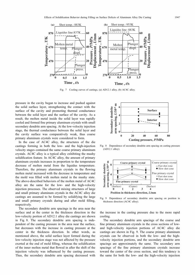
pressure in the cavity began to increase and pushed againstthe solid surface layer, strengthening the contact with thesurface of the cavity and promoting thermal conductancebetween the solid layer and the surface of the cavity. As aresult, the molten metal inside the solid layer was rapidlycooled and formed fine primary aluminum crystals with smallsecondary dendrite arm spacing. At the low-velocity injectionstage, the thermal conductance between the solid layer andthe cavity surface was comparatively weak, thus coarseprimary aluminum crystals were considered to form.
In the case of AC4C alloy, the structures of the diecastings forming in both the low- and the high-injectionvelocity stages contained the same coarse primary aluminumcrystals. AC4C alloy is a typical alloy exhibiting the mushysolidification feature. In AC4C alloy, the amount of primaryaluminum crystals increases in proportion to the temperaturedecrease of molten metal from the liquidus temperature.Therefore, the primary aluminum crystals in the flowingmolten metal increased with the decrease in temperature andthe mold was filled with molten metal in the mushy state.The above-described behaviors of the molten metal of AC4Calloy are the same for the low- and the high-velocityinjection processes. The observed mixing structures of largeand small primary aluminum crystals in the AC4C alloy diecastings are assumed to be formed by solidifying the largeand small primary crystals during and after mold filling,respectively.
The secondary dendrite arm spacings in the area near thesurface and at the center in the thickness direction in thelow-velocity portion of AD12.1 alloy die castings are shownin Fig. 8. The secondary dendrite arm spacing is inde-pendent of the casting pressure in the area near the surface,but decreases with the increase in casting pressure at thecenter in the thickness direction. In other words, asmentioned above, the solid surface layer formed during thelow-velocity injection stage was not affected by the pressureexerted at the end of mold filling, whereas the solidificationof the inner molten metal that flowed in after the shift of theinjection velocity was influenced by the casting pressure.Thus, the secondary dendrite arm spacing decreased with
the increase in the casting pressure due to the more rapidcooling.
The secondary dendrite arm spacings of the coarse andfine primary aluminum crystals in the cross sections of low-and high-velocity injection portions of AC4C alloy diecastings are shown in Fig. 9. The coarse primary aluminumcrystals can be observed in both the low- and the high-velocity injection portions, and the secondary dendrite armspacings are approximately the same. The secondary armspacings of the fine primary aluminum crystals increasetoward the center of the cross section, and this tendency isthe same for both the low- and the high-velocity injection
Shot temp. 883K
270
470
670
870
0 0.5 1.0 1.50
20
40
60
Time , t/s
Tem
pera
ture
, T
/K
Dis
plac
emen
t , L
/mm
Pre
ssur
e , P
/MP
a
Liquidus line:837K
Molten metal temp. Plunger
displ.
Plunger press.
(a) (b)
Plunger press.
Plunger displ.
Molten metal temp.
Liquidus line 883K
0
20
40
60
0 0.5 1.0 1.5
470
670
870
Tem
pera
ture
, T
/K
Time , t/s
Dis
plac
emen
t , L
/mm
Pre
ssur
e , P
/MP
a
Shot temp. 953K
270
Fig. 7 Cooling curves of castings, (a) AD12.1 alloy, (b) AC4C alloy.
Surface
0 20 40 60 800
2
4
6
Casting pressure, P/MPa
Seco
ndar
y de
ndri
te
arm
spa
cing
, L/1
0-6m
Interior
Fig. 8 Dependence of secondary dendrite arm spacing on casting pressure(AD12.1 alloy).
Coarse primary crystal
Fine primary crystal
Fast shot zoneSlow shot zone
Fast shot zoneSlow shot zone
Coarse primary crystal
Fine primary crystal
0 1 2 3 4
0
4
8
(Surface) (Surface)(Center)
Position in thickness direction, L/mm
Seco
ndar
y de
ndri
te
arm
spa
cing
, L/1
0-6 m
Fig. 9 Dependence of secondary dendrite arm spacing on position inthickness direction (AC4C alloy).
Effects of Solidification Behavior during Filling on Surface Defects of Aluminum Alloy Die Casting 1947
portions. This result supports the assumption that the moltenmetal is strongly cooled due to the start of the pressureincrease at the end of mold filling. In other words, unlikeAD12.1 alloy, in which high-velocity molten metal flowsinto the cavity inside the low-velocity molten metal, in thecase of AC4C alloy, the subsequently injected molten metalcontaining primary aluminum crystals pushes the moltenmetal injected during the low-velocity injection stage, andthe metals flow together.
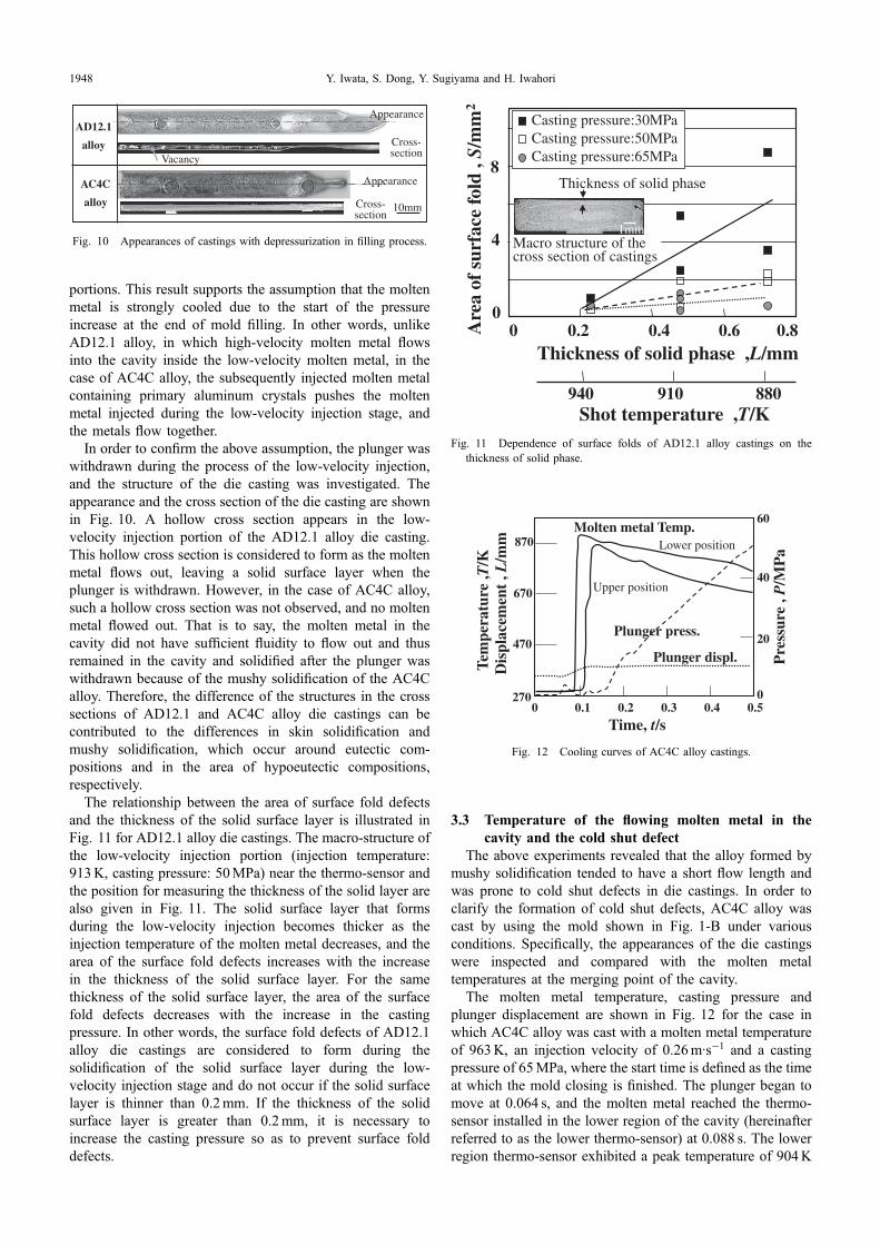
In order to confirm the above assumption, the plunger waswithdrawn during the process of the low-velocity injection,and the structure of the die casting was investigated. Theappearance and the cross section of the die casting are shownin Fig. 10. A hollow cross section appears in the low-velocity injection portion of the AD12.1 alloy die casting.This hollow cross section is considered to form as the moltenmetal flows out, leaving a solid surface layer when theplunger is withdrawn. However, in the case of AC4C alloy,such a hollow cross section was not observed, and no moltenmetal flowed out. That is to say, the molten metal in thecavity did not have sufficient fluidity to flow out and thusremained in the cavity and solidified after the plunger waswithdrawn because of the mushy solidification of the AC4Calloy. Therefore, the difference of the structures in the crosssections of AD12.1 and AC4C alloy die castings can becontributed to the differences in skin solidification andmushy solidification, which occur around eutectic com-positions and in the area of hypoeutectic compositions,respectively.
The relationship between the area of surface fold defectsand the thickness of the solid surface layer is illustrated inFig. 11 for AD12.1 alloy die castings. The macro-structure ofthe low-velocity injection portion (injection temperature:913K, casting pressure: 50MPa) near the thermo-sensor andthe position for measuring the thickness of the solid layer arealso given in Fig. 11. The solid surface layer that formsduring the low-velocity injection becomes thicker as theinjection temperature of the molten metal decreases, and thearea of the surface fold defects increases with the increasein the thickness of the solid surface layer. For the samethickness of the solid surface layer, the area of the surfacefold defects decreases with the increase in the castingpressure. In other words, the surface fold defects of AD12.1alloy die castings are considered to form during thesolidification of the solid surface layer during the low-velocity injection stage and do not occur if the solid surfacelayer is thinner than 0.2mm. If the thickness of the solidsurface layer is greater than 0.2mm, it is necessary toincrease the casting pressure so as to prevent surface folddefects.
3.3 Temperature of the flowing molten metal in thecavity and the cold shut defect
The above experiments revealed that the alloy formed bymushy solidification tended to have a short flow length andwas prone to cold shut defects in die castings. In order toclarify the formation of cold shut defects, AC4C alloy wascast by using the mold shown in Fig. 1-B under variousconditions. Specifically, the appearances of the die castingswere inspected and compared with the molten metaltemperatures at the merging point of the cavity.
The molten metal temperature, casting pressure andplunger displacement are shown in Fig. 12 for the case inwhich AC4C alloy was cast with a molten metal temperatureof 963K, an injection velocity of 0.26m·s¹1 and a castingpressure of 65MPa, where the start time is defined as the timeat which the mold closing is finished. The plunger began tomove at 0.064 s, and the molten metal reached the thermo-sensor installed in the lower region of the cavity (hereinafterreferred to as the lower thermo-sensor) at 0.088 s. The lowerregion thermo-sensor exhibited a peak temperature of 904K
Cross-section
Cross-section
AD12.1
alloy
AC4C
alloy
Vacancy
Appearance
Appearance
10mm
Fig. 10 Appearances of castings with depressurization in filling process.
Casting pressure:30MPaCasting pressure:50MPaCasting pressure:65MPa
Are
a of
sur
face
fold
, S/
mm
2
0 0.2 0.4 0.6Thickness of solid phase ,L/mm
0.80
4
8
Macro structure of the cross section of castings
Thickness of solid phase
940 910 880Shot temperature ,T/K
1mm
Fig. 11 Dependence of surface folds of AD12.1 alloy castings on thethickness of solid phase.
270
470
670
870
Tem
pera
ture
,T/K
Dis
plac
emen
t , L
/mm
0 0.1 0.2 0.3 0.4 0.5
20
40
60
0
Pre
ssur
e , P
/MP
a
Time, t/s
Molten metal Temp.
Upper position
Lower position
Plunger press.
Plunger displ.
Fig. 12 Cooling curves of AC4C alloy castings.
Y. Iwata, S. Dong, Y. Sugiyama and H. Iwahori1948

at the time of 0.01 s after touching the molten metal. Themolten metal reached the thermo-sensor installed in the upperregion of the cavity (hereinafter referred to as the upperthermo-sensor) at 0.1 s, and the upper thermo-sensorexhibited a peak temperature of 867K at the time of 0.02 safter touching the molten metal. The plunger eventuallystopped moving at 0.13 s. The temperature of the lowerthermo-sensor was always higher than that of the upperthermo-sensor during mold filling, i.e., molten metal of ahigher temperature than that of the upper region continued toflow through the lower region of the cavity during the moldfilling. Each thermo-sensor had a response time of 0.015 sand exhibited a peak temperature within 0.02 s after touchingthe molten metal.
By defining the temperature indicated by the thermo-sensor at the time of 0.2 s after touching the molten metal asthe temperature of the tip of the molten metal, we calculatedthe temperature of the molten metal upon first arriving at thecenter of the apex of the cavity. Specifically, we extrapolatedthe tip temperature based on the relationship between thefilling fraction of the cavity and the flowing distance of themolten metal. Figure 13 illustrates the temperature decreaseof the tip of flowing molten metal injected under variouscasting conditions. The temperature of the molten metal uponarriving at the center of the apex of the cavity is estimated tofall to as low as 803K under an injection temperature of993K and an injection velocity of 0.20m·s¹1. When theinjection velocity was increased to 0.26m·s¹1, the moltenmetal temperatures at the moment of reaching the center ofthe apex were estimated to be 840 and 863K for injectiontemperatures of 963 and 993K, respectively, i.e., thetemperature decrease was not so large. Comparing theabove-estimated temperatures of the tip of the molten metalat the merging point revealed that the temperature drop of themolten metal in the cavity was more significantly affected bythe injection velocity than the injection temperature of themolten metal.
The investigation results for surface fold and cold shutdefects of AC4C alloy die castings are shown in Fig. 14,together with the temperature of the molten metal at themerging point when varying the injection velocity andinjection temperature of the molten metal. The defects were
quantified by measuring the areas of the dented portions onthe surfaces of die castings. Photographs of appearancesnear the merging point of the die castings (apex of thecavity) are also shown in Fig. 14. For the case in which themolten metal temperature is estimated to be 803K uponmerging at the center of the apex of the cavity, the apex ofthe cavity is not fully filled and the die casting has a misrundefect. The above result can be easily explained byconsidering the fact that the temperature of 803K is belowthe liquidus temperature of AC4C alloy. Therefore, theestimated temperature of the molten metal upon first arrivingat the center of the apex of the cavity can be considered tobe a reasonable value. For the case in which the moltenmetal temperature is estimated to be 843K upon mergingat the center of the apex of the cavity, although the apex ofthe cavity is almost fully filled, the molten metals do notadhere to each other and an obvious cold shut is left onthe die casting. When the tip temperature of the moltenmetal on merging is as high as 858K, molten metals adherewell to each other and only a minor cold shut is observed.Thus, the extent of the cold shut can be considered todepend on the tip temperature of the molten metal whenmerging at the center of the apex of the cavity. It can beconcluded that if the tip temperature of the molten metalwhen merging at the center of the apex is higher than 858K,no surface defects will occur. If the tip temperaturedecreases to a value lower than 858K, cold shut defectswill begin to occur and will deteriorate as the tip temper-ature decreases further.
4. Conclusions
Surface fold and cold shut defects of die castings wereinvestigated with respect to the temperature of molten metalduring mold filling through experimental die casting. Basedon the results, we present the following conclusions.(1) For AD12.1 alloy, the molten metal solidifies from the
wall of the mold cavity toward the center of the crosssection, forming a solid surface layer during moldfilling. If the temperature of the molten metal decreasedtoo much, the solid surface layer becomes thicker and
0 4000 8000 12000
770
870
970
1070
Filling volume, V/mm3
Tem
pera
ture
,T/K
Meeting position
Shot temp.Measured temp.
Lower position
Upper position
Extrapolation
Shot velocity:0.26m/sShot velocity:0.26m/sShot velocity:0.20m/s
Fig. 13 Colling behavior of AC4C molten metal halfway through fillingup.
Metal temperature at meeting position ,T/K790 810 830 850 870
0
0.3
0.6
0.9
2.0
Are
a of
sho
rt p
orti
on, S
/cm
2
Cold shut
Cold shut
Misrun
10mm
Fig. 14 Dependence of cold shut of AC4C alloy castings on molten metaltemperature.
Effects of Solidification Behavior during Filling on Surface Defects of Aluminum Alloy Die Casting 1949

the contact with the cavity wall weakens, resulting insurface fold defects. The critical thickness of the solidsurface layer at which surface fold defects form wasfound to be 0.2mm for AD12.1 alloy.
(2) For AC4C alloy, solid phase crystallizes and increasesinside the molten metal as the mold filling proceeds,and the cavity is filled with molten metal in the liquid-solid coexisting state. For alloys formed by mushysolidification, some liquid metal remains in the vicinityof the cavity wall, even at the end of mold filling andthe contact between the cavity wall and the surface ofthe die casting is strengthened by the casting pressure,and thus, no surface fold defects occur.
(3) In the mold filling process of AC4C alloy, thetemperature decrease of the molten metal increaseswith the flow length in the cavity and close to the tip ofthe molten metal flow. The cold shut defects that occurin alloys formed by mushy solidification depend on thetemperature of the molten metal and begin to occur asthe tip temperature of the molten metal flow decreasesto a low threshold value.
REFERENCES
1) Y. Iwata, S. Dong, Y. Sugiyama and H. Iwahori: JFS 83 (2011) 421426.
2) Y. Iwata, S. Dong, Y. Sugiyama and H. Iwahori: Mater. Trans. 53(2012) 483488.
3) S. Tanikawa, K. Asai, Y. Yang, H. Nomura and E. Kato: Rep. JFSMeeting 139 (2001) p. 134.
4) Y. Sugiyama, H. Iwahori, K. Yonekura and Y. Ookochi: IMONO 66(1994) 412417.
5) N. Nishi, H. Sasaki, T. Hirabara and Y. Takahashi: IMONO 60 (1988)777783.
6) Y. Iwata, Y. Yamamoto, M. Nakamura, K. Mizuno and S. Tsuboi:J. Jpn. Inst. Light Met. 39 (1989) 550554.
7) Y. Iwata, K. Tozawa, Y. Yamamoto, M. Nakamura, K. Mizuno and M.Tsuboi: J. Jpn. Inst. Light Met. 37 (1987) 4852.
8) Y. Yamamoto, Y. Iwata and M. Nakamura: IMONO 60 (1988) 770776.
9) Y. Iwata, K. Tozawa, Y. Yamamoto, M. Nakamura and A. Sasaoka:J. Jpn. Inst. Light Met. 36 (1986) 1014.
10) Y. Iwata, K. Tozawa, Y. Yamamoto and M. Nakamura: ALUMINIUM63 (1987) 6669.
11) JFS (ed.): Imonoyougojiten, (JFS, Tokyo, 1988) p. 258.12) H. Iwahori and Y. Iwata: J. JSPE 73 (2007) 183187.
Y. Iwata, S. Dong, Y. Sugiyama and H. Iwahori1950