Embed Size (px)
Citation preview

Effects of Combined Corrosion and Fatigue on Rail Performance
Dr. George W. Ritter, EWI, 1250 Arthur E. Adams Drive, Columbus OH, 43221.614-688-5199, [email protected]
Dr. William C. Mohr, EWI 1250 Arthur E. Adams Drive, Columbus OH, 43221614-688-5182, [email protected]
Cameron D. Stuart, Federal Railroad Administration, 1200 New Jersey Avenue SE, Washington, DC, 20590
202-493-6384, [email protected]. David Y. Jeong, Volpe National Transportation Systems Center, Kendall Square,
Cambridge, MA 02142-1093617-494-3654, [email protected]
Yim Har Tang, Volpe National Transportation Systems Center, Kendall Square, Cambridge, MA 02142-1092
617-494-2717, [email protected]
Number of Words: 3921; 13 figures and tables.
ABSTRACT
Rail base corrosion induced by water or saltwater can deteriorate rail strength which may ultimately lead to failure and safety issues. The combination of fatigue and corrosion are expected to accelerate the rate of deterioration. In this study, rail segments were tested for fatigue life with and without corrosion protection, with and without induced damage, and with or without exposure to corrosive environments. The purpose was to separate and elucidate the effects of fatigue and corrosion on rail life and to determine if corrosion protection is of practical value. It was found that the effects can be separated and that corrosion protection can improve rail life in the presence of both fatigue and corrosive environments.
INTRODUCTION
Corrosion of rails is a pernicious problem that can lead to dangerous deterioration of strength in service. This is particularly a concern in areas where rail may be exposed to drip zones from overpasses, high water from rain storms, or road deicing salt that is tracked at grade-level crossings or into tunnels by rolling stock. In-service rail is constantly subjected to fatigue. Over time, small cracks can develop in the flange region. Incipient fatigue cracks are intuitively suspect as locations where corrosive attack might have more effect at increasing crack growth with time or accelerating the general deterioration of the rail through corrosion (1). The problem can also be exacerbated by leakage currents on electrified rail (2).
TECHNICAL BACKGROUND on CORROSION INTERVENTION
The chemistry of steel rusting is complex, but there are opportunities to intervene, chemically in the cycle and reverse or retard the progress of corrosion (1). Ferrous iron
© AREMA 2013® 281

(Fe+2) as FeO is a more stable form of oxide than ferric iron (Fe+3) as Fe2O3. The ferric iron oxide form is the common red rust. If the oxidation of ferrous iron (Fe+2) ferric iron (Fe+3) can be eliminated or retarded, the ferrous state will predominate giving the more stable form of rust. This can be accomplished by introducing a reducing agent into a surface treatment that will preferentially reduce ferric ion (Fe+3) back to ferrous iron (Fe+2). This can retard “rusting” or allow formation of the mixed form of the oxide, FesO3 FeO (or Fe3O4), which is also fairly stable. This approach is one way of attacking the corrosion problem.
Another approach for passivating the surface is to apply a topical conversion coating that naturally repels water. Iron phosphate and aluminum phosphate are naturally resistant to water and corrosion attack, especially aluminum phosphate. This passivation approach was the second approach chosen.
These two surface treatment approaches were incorporated into the program to investigate their effectiveness in corrosion protection or mitigation on steel rails. They were studied in combination with purposeful pre-cracking of the rails, corrosion cycles, and fatigue tests to separate the combined effects into their component contributions to the overall failure of the rail section in fatigue.
PROGRAM OBJECTIVE and EXPERIMENTAL APPROACHProgram Objective
In a previous study for the US Department of Energy, EWI had investigated an approach to corrosion mitigation on steels using a passivating treatment with a quasi-ceramic sealer (3). This had shown good resistance to liquid water operating at 570oFand 1250 psi. The EWI coating approach includes a reversible reducing agent that preferentially forms and stabilizes the mixed oxide Fe3O4 form. The ceramic sealer is believed to provide additional resistance to water.
The commercial product EonCoat® is a two-component, spray-applied material that reacts with the iron surface to produce a complex mixture of iron and aluminum phosphates (4). While it builds a barrier layer onto the surface, even if that barrier is lost, the surface conversion remains intact and effective unless the converted zone of the surface is itself compromised or destroyed, such as by gouging or severe abrasion.
Under a contract to the Federal Railroad Administration, EWI was engaged to perform an experimental study into the effects of combined corrosion and fatigue on rails and also to investigate possible corrosion mitigation strategies based on the EWI coating system and the EonCoat® material. This paper reports the experimentation during the study and results of the study.
Program Experimental Approach
A high-level Work Breakdown Structure diagram is given in Figure 1. This study was divided into four tasks. The first task was to apply treatments to small coupons and
© AREMA 2013®282

evaluate their effects on corrosion and surface chemistry. That work is not reported on here, but served as the basis for the follow-on work. Medium scale specimens (18-inches long) and longer rail sections (twenty-feet long) were prepared for studies on the combined effects of corrosion and fatigue (Tasks 2, 3, and 4).
Figure 1. High Level Work Breakdown Structure for the Program
DESCRIPTION OF EXPERIMENTAL WORK
All the rail sections referred to below were taken from 136-lb standard chemistry rail.
Coating Systems
EWI Three-Part Coating System
The EWI system requires three treatment steps. All can be spray or brush applied. The first is to treat the rail section with 10% phosphoric acid solution (by weight in water). For large rail sections, the surface rust is ground off. Optionally, grit blasting can be used to remove the rust to get down to base metal. Drying after the phosphoric acid application produces a white, powdery material on the surface. The surface is then wiped with water to remove the excess crystal formation.
Next, the phosphated rail is treated with the di-phenolic reducing agent, alsobrush applied. A deep blue-black color evolves, indicating the formation of the mixed metal oxide. After drying for 4-6 hours, this too is washed with water to remove excess.
The third step consists of applying a zirconia sol-gel. A sol-gel is a ceramic precursor solution derived from an organometallic precursor. The precursor hydrolyzes to form an oxy-hydroxide zirconate that can be heated to form zirconium oxide ceramic. The preparation of this material was taken from the literature (5). It was found that a temperature maintained at1000oF for 3 hr was sufficient to convert the sol-gel to a form of zirconium oxide. This temperature is well below the transition temperature between ferrite and austenite for common rail steels (~1300oF), thus avoiding marteniste formation. The hardness of these treated steels never dropped below 325 Brinell.
Task 1 Task 2 Task 3 Task 4
Analyze Surface Chemistry on
Rail (Small Scale)
Treatments on Rail Stock
(Medium Scale)
Crack Fatigue Propagation and
Mitigation (Medium Scale)
Resonant Fatigue Testing (Rail Sections)
Rail Base Corrosion and Cracking Prevention
© AREMA 2013® 283

In the three-step process, for the final bake, the medium-scale specimens were heated in a muffle furnace. Large rail sections were heated using resistance heating blankets for welding. There is a variant using only the first two steps where the the zirconia sol-gel and baking cycle are eliminated. That two-step approach was also tested for effectiveness.
A treated tie plate, flange base, and small witness coupon are shown as treated in Figure 2. For the corrosion cycles, the flange piece was nested into the tie plate to simulate a corrosion antagonist trapped between the rail and the tie plate.
Figure 2. Specimens Treated with the EWI Three-Step Process after Baking
Figure 3 shows a rail segment that has been treated with the three-step process and is wrapped with heater blankets prior to the bake cycle. An insulating layer of ceramic fiber blanket was then placed over the heating area. In practice, the rail outside the heating zone stayed quite cool.
© AREMA 2013®284

Figure 3. Resistance Heating Blankets used to Heat Cure the Zirconia Sol-Gel Sealer
EonCoat®
EonCoat® is a commercially spray-applied ceramic coating (4). The overall formulation is proprietary. Standard two-component spray equipment is used with a mixer-headnozzle (Figure 4). It dries within minutes of application. A second coat can be applied in about 10-15 minutes, which was the practice used here. Smaller flange segments were treated at EonCoat® by the manufacturer. A large rail segment was spray coated at EWI by EonCoat®. That rail segment is shown in Figure 5. There is evidence of some debonding of the spray at the edges (circled in Figure). These areas are outside the regions that had excess rust removed by grinding.
© AREMA 2013® 285

Figure 4. Technician Readies the EonCoat® Applicator System
Figure 5. EonCoat® Sprayed Rail Segment
© AREMA 2013®286

Saltwater Solution
The saltwater solution used as a corrosion antagonist consisted of 5% (by weight in water) road deicing salt dissolved in tap water. The deicing salt contained sodium chloride, magnesium chloride, and calcium chloride.
Sample Disposition and Corrosion Cycles
Medium-Scale Flange Specimens
Samples were prepared with and without pre-notch damage in the flange base, with and without protective coatings, and with and without corrosion attack. Ultimately, they were subjected to fatigue.
The medium-scale flange segments were taken from rail sections of ~18-inches length. The heads and the web portions were removed to leave just the flange base. If the base was to be pre-damaged, a notch was cut across the flange bottom in the center of the base. The notch was about 1/8” wide and about 1/16” deep.
Medium-Scale Segments: Specimen Disposition
The medium-scale test articles were destined for testing using four-point load fatigue in a servohydraulic testing machine. The specimen disposition for the medium-scale test articles is given below along with a brief description of the experimental relevance for each test article.
Untouched flange base, no damage, no corrosion exposure. This specimen serves as a baseline for untouched rail.Notched base (damage), but no corrosion exposure. This specimen serves to separate the mechanical effect of damage in the absence of corrosion.Notched base, no treatments, corrosion exposure. This specimen demonstrates the added effect of corrosion with damage presence. This may approximate a rail segment that has been in service for some time and has weathered.Notched base, EWI three-step treatment, corrosion exposures. This specimen shows the effect of corrosion abatement on fatigue life for a damaged rail.Notched base, EWI two-step treatment, corrosion exposure. Compares two-step and three-step processes for effectiveness.Notched base, EonCoat® treatment, corrosion exposure. Shows the effect of this anti-corrosion treatment.
Corrosion Cycles for Medium-Scale Test Articles
The corrosion cycle consisted of the following:Place in saltwater solution with flange resting on tie-plate – 2 days.Remove and separate pieces, air dry – 1 day
© AREMA 2013® 287

Place in humidity cabinet (120oF / 98-100%RH) with flange nested in tie plate, once again – 3 daysRemove and separate components, air dry – 1 day
Each corrosion exposure cycle spanned one week and was repeated twice for a total of three weeks exposure.
Fatigue Testing for Medium-Scale Test Articles
The flange sections had slightly differing geometries, based on differing cut locations at the radius between the flange and the web. Each had a 16-inch span between the outer rollers with the inner rollers having an 8-inch span. For R=0.1, the maximum load range was 11.5 – 15.8 x10³ lb and the minimum load range was therefore about 1.2 – 1.6 x 10³ lb. Frequency was 5 Hz. Fatigue testing was performed with the combined application of salt water contained near the center bottom.
To provide the same nominal stress on the lower flange surface during fatigue testing, different load levels were chosen to account for the differences in specimen size.
Twenty-Foot Rail Sections
The twenty-foot rail sections were used for testing using a fatigue method called resonant fatigue. Resonant fatigue methodology has been most commonly applied to testing of welds in drill pipe. It has been adapted at EWI for use also on rail segments.
In this method, the rail is suspended between two support points. Acounterweight of calculated size is attached to one end. The correct excitation, provided by an eccentric drive cam at the opposite end, forces the rail into self-resonance around the center point. Strain gauges monitor the cyclic strains at several locations on the part. At some point, a crack will grow to sufficient size to cause the rail to yield. This is the failure point at which the machine stops and the cycles to failure are noted. In this case, the rail was excited to give a self-resonance at about 21 Hz. The excitation and self-resonance induce a stress on the rail head of 28-30 ksi and a stress on the rail base of 25-26 ksi. An example of a loaded test article is shown in Figure 6.
© AREMA 2013®288

Figure 6. Rail Suspended in Resonant Fatigue Apparatus
Twenty-Foot Test Articles: Specimen Disposition for Resonant Fatigue TestingThere were five test articles for resonant fatigue. Their sample disposition was:
RS1 - Notched, untreated, no corrosion. Effect of damage alone.RS2 - Notched, untreated, corrosion. Effect of damage and corrosioncombined.RS3 - Notched, treated with EWI three-step system, corrosion exposure.Relative corrosion mitigation effect of the EWI system.RS4 - Notched, treated with EonCoat®, corrosion exposure. Relative corrosion mitigation effect of this system.
The surface preparation method for the twenty-foot rail sections was modified,given their size. Surface rust was ground off to a distance of about two feet to either side of the center line on the bottom of the flange only. If notched, the notch was cut across the flange at the ten-foot point. No tie plates were used in the corrosion exposure.
Corrosion Cycles for Full-Scale Test Articles (Resonant Fatigue Testing)
The basic cycle was as outlined above for the medium-scale specimens, but adjustments were made to accommodate the size difference. Soaking in a tank was impossible, for example, and humidity exposure was a complicated undertaking. For the saltwater exposure, the rails were brushed with saltwater solution. Then, a “diaper” was prepared to keep the solution in contact. First, paper towels soaked in saltwater were papered onto the surface. A lofted fabric, also soaked in saltwater, was then applied. That whole assembly was wrapped in place with shrink wrap to retain the solutions in contact with the rail and the notch region. For air drying, the diaper was cut off and
© AREMA 2013® 289

discarded. The same procedure was used substituting water for saltwater to give the required three-day humidity exposure. The cycle time lengths were the same as before and overall the exposure lasted three weeks.
RESULTSCorrosion of Medium Scale Specimens
Figure 7 shows the un-protected specimen after corrosion, Figure 8 shows the three-step treated specimen after corrosion, and Figure 9 shows the EonCoat® specimen after corrosion.
Figure 7. Unprotected Flange and Tie Plate after Cyclic Corrosion
© AREMA 2013®290

Figure 8. Three-Step Treated Flange and Tie Plate after Cyclic Corrosion
Figure 9. EonCoat® Treated Flange and Tie Plate after Cyclic Corrosion
The unprotected specimen clearly has undergone severe corrosion. The three-step protection system shows good protection in the notch zone, but corrosion is beginning to creep in from the edges. Based on visual examination, the EonCoat® system has provided the best corrosion protection.
© AREMA 2013® 291

A “drip zone” is a region where rail would be exposed to condensing water, but not necessarily saltwater, that might drip from an overpass, for example. A drip-zone specimen, protected on the bottom half with the three-step method, is shown in Figure 10. The corrosion cycle for drip zone testing also lasted three weeks, but instead of saltwater soaks for two days, the specimens spent an additional two days in the humidity cabinet, producing a total of five days of humidity each week broken into two-day and three-day segments.
Figure 10. Bottom of Treated Drip Zone Specimen
The bottom half of the flange base is the treated portion. The top, untreated portion has completely evolved into rust. The bottom portion shows invasive rust from the lower edge but is also that invasion was less over the exposure time period. While complete protection has not been afforded, there has been retardation of rusting.
Fatigue of Medium-Scale Specimens
Samples that had undergone corrosion cycling were tested with an applied saltwater “diaper” which kept saltwater in contact with the notch zone during testing. The results for the four-point fatigue testing on the medium-scale specimens are given in Table 1. Those tested in contact with continuous corrosion exposure during testing are specimens 3 6 in Table 1.
© AREMA 2013®292
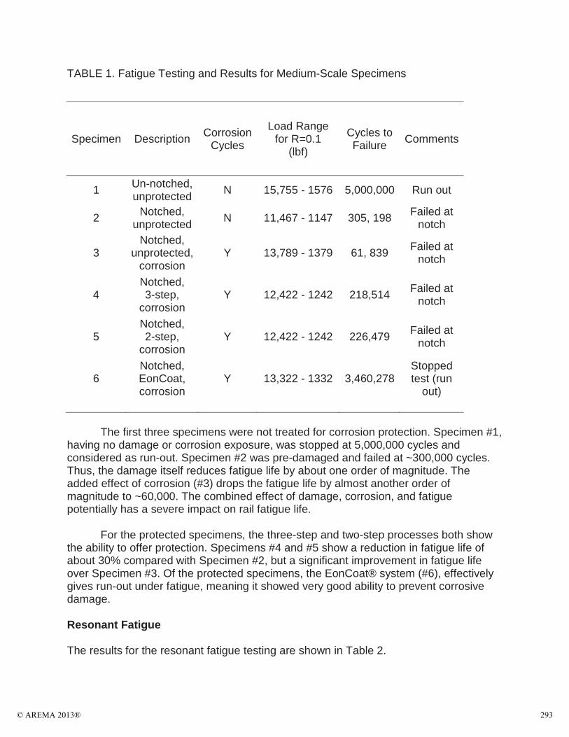
TABLE 1. Fatigue Testing and Results for Medium-Scale Specimens
Specimen Description Corrosion Cycles
Load Range for R=0.1
(lbf)
Cycles to Failure Comments
1 Un-notched, unprotected N 15,755 - 1576 5,000,000 Run out
2 Notched, unprotected N 11,467 - 1147 305, 198 Failed at
notch
3Notched,
unprotected, corrosion
Y 13,789 - 1379 61, 839 Failed at notch
4Notched, 3-step,
corrosionY 12,422 - 1242 218,514 Failed at
notch
5Notched, 2-step,
corrosionY 12,422 - 1242 226,479 Failed at
notch
6Notched, EonCoat, corrosion
Y 13,322 - 1332 3,460,278Stopped test (run
out)
The first three specimens were not treated for corrosion protection. Specimen #1, having no damage or corrosion exposure, was stopped at 5,000,000 cycles and considered as run-out. Specimen #2 was pre-damaged and failed at ~300,000 cycles. Thus, the damage itself reduces fatigue life by about one order of magnitude. Theadded effect of corrosion (#3) drops the fatigue life by almost another order of magnitude to ~60,000. The combined effect of damage, corrosion, and fatigue potentially has a severe impact on rail fatigue life.
For the protected specimens, the three-step and two-step processes both show the ability to offer protection. Specimens #4 and #5 show a reduction in fatigue life of about 30% compared with Specimen #2, but a significant improvement in fatigue life over Specimen #3. Of the protected specimens, the EonCoat® system (#6), effectively gives run-out under fatigue, meaning it showed very good ability to prevent corrosive damage.
Resonant Fatigue
The results for the resonant fatigue testing are shown in Table 2.
© AREMA 2013® 293

TABLE 2. Summary of Testing using Resonant Fatigue
Specimen Description Corrosion Cycles
Rail Head Stress (ksi)
Rail Base Stress (ksi)
Cycles to Failure Comments
RS1 Notched, unprotected N 28.6 25 109,888 Failed in
crack
RS2Notched,
unprotected, corrosion
Y 30 26.4 133,291 Failed in crack
RS3
Notched, 3-step
protected, corrosion
Y 29.3 26.3 967,968 No fail, but rusted
RS4Notched, EonCoat, corrosion
Y 29.8 25.7 94,745 Failed in crack
In comparing the character of the fracture surfaces with those for the medium-scale specimens, the resonant fatigue specimens showed much larger regions of fatigue cracking than those visible on the medium-scale specimens. This difference is attributed to the larger cross-section of the full rail inducing a higher stress intensity factor in the rail at the fatigue crack tip, allowing brittle fracture to take over from fatigueat a smaller crack size.
Specimens RS1 – RS4 were pre-notched before treatments, corrosion cycles, or testing. Therefore, the notched zone saw the same corrosion history as the rail itself. RS1 was not protected from corrosion, but it also did not see purposeful corrosion cycles. Sample RS2 was unprotected, but did undergo corrosion cycling and also had a saltwater solution “diaper” applied during resonant fatigue. It represented older rail in service that had somehow been damaged and suffered corrosion attack. It failed in the crack zone, but showed slightly higher fatigue life despite the corrosion and lack of protection. Rust formation is clearly evident in the failure zone (Figure 11).
Specimen RS3 was notched and had the EWI 3-step corrosion protection applied prior to being subjected to corrosion cycles. It also had the saltwater diaper applied during resonant fatigue. It did not fail during testing, which was a perplexing result. It is possible the notch rusted significantly enough to “heal”. The EonCoat® specimen (RS4)showed approximately the same number of cycles to failure as the notched specimen that had not been corroded (RS1). This result supports the earlier finding that the corrosion protection was effective in preventing corrosive attack, even on damaged rail.
© AREMA 2013®294
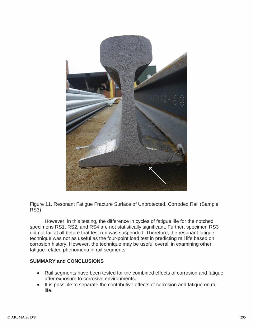
Figure 11. Resonant Fatigue Fracture Surface of Unprotected, Corroded Rail (Sample RS3)
However, in this testing, the difference in cycles of fatigue life for the notched specimens RS1, RS2, and RS4 are not statistically significant. Further, specimen RS3did not fail at all before that test run was suspended. Therefore, the resonant fatigue technique was not as useful as the four-point load test in predicting rail life based on corrosion history. However, the technique may be useful overall in examining other fatigue-related phenomena in rail segments.
SUMMARY and CONCLUSIONS
Rail segments have been tested for the combined effects of corrosion and fatigue after exposure to corrosive environments. It is possible to separate the contributive effects of corrosion and fatigue on rail life.
© AREMA 2013® 295

The presence of corrosion significantly reduces rail fatigue life.Anti-corrosion treatments can be of benefit in extending fatigue life in corrosive environments. The EonCoat® system showed very good protection in extremely corrosive environments. The EWI system may be useful in drip zones, where the corrosion attack is less aggressive.Both systems can be applied in the field, however access to the flange bottom and tie plate(s) is required in both cases. The EWI system requires a bake cycle. A resonant fatigue technique has been used to study fatigue life on rail sections.This test method can be accommodate long rail segments (twenty feet) and may be a useful screening tool for examining fatigue-related rail failure. Demonstration of effectiveness of any treatment requires field testing, which would be the next phase of this program.
ACKNOWLEDGEMENTS
This work was sponsored by the Federal Railroad Administration of the US Department of Transportation under contract number DTFR-12-C-0024. The authors gratefully acknowledge that support and the cooperation of the Volpe National Transportation Systems Center. We also thank EonCoat® Corporation for the donation of their time,materials, and services. Finally we acknowledge several helpful conversations organized through Volpe and FRA Region 1 field office including discussions with Amtrak, LIRR, PATH, and Metro North.
REFERENCES
1. Roblez-Hernandez, F.C., Plascensia, G., Koch, K. “Rail Base Corrosion Problem for North American Transit Systems”, Engineering Failure Analysis 16(1), 2009,p281-294.
2. Roblez-Hernandez, F.C., Kock, K. “Rail-base Corrosion Analysis: A Major Factor that Shortens Service Life of Rail in North American Transit”, TMS Annual Meeting, p39-54, 2007.
3. EWI Research report for Project No. 52684GTH.4. EonCoat LLC, 4000 Airport Drive, Wilson, NC, 27896.5. H. Li, K. Liang, L. Mei and S. Gu, “Oxidation Resistance of Mild Steel by Zirconia
Sol–Gel Coatings”, Mater. Sci. and Eng. A, 341, 2003, p87-90,
LIST of TABLES
Table 1. Fatigue Testing and Results for Medium-Scale SpecimensTable 2. Summary of Testing using Resonant Fatigue
LIST of FIGURES
Figure 1. High Level Work Breakdown Structure for the ProgramFigure 2. Specimens Treated with the EWI Three-Step Process after BakingFigure 3. Resistance Heating Blankets used to Heat Cure the Zirconia Sol-Gel Sealer
© AREMA 2013®296

Figure 4. Technician Readies the EonCoat® Applicator SystemFigure 5. EonCoat® Sprayed Rail SegmentFigure 6. Rail Suspended in Resonant Fatigue ApparatusFigure 7. Unprotected Flange and Tie Plate after Cyclic CorrosionFigure 8. Three-Step Treated Flange and Tie Plate after Cyclic CorrosionFigure 9. EonCoat® Treated Flange and Tie Plate after Cyclic CorrosionFigure 10. Bottom of Treated Drip Zone SpecimenFigure 11. Resonant Fatigue Fracture Surface of Unprotected, Corroded Rail (Sample RS3)
BIOSKETCH
Dr. George Ritter is a Principal Engineer in Materials Technology at EWI in Columbus, OH. He specializes in adhesives bonding and processes relating to structural bonding and adhesion. A major component of that work has been the investigation of corrosion protection systems for marine-grade carbon steels specific to structural bonding of composites. Further, he has extensive experience in applying relevant surface preparation techniques for aluminum, titanium, stainless steels, rubber, and elastomers.
© AREMA 2013® 297
Sept
embe
r 29
–O
ctob
er 2
, 20
13In
dian
apol
is,
IN
Effe
cts
of C
ombi
ned
Corr
osio
n an
d Fa
tigue
on
Rail
Perf
orm
ance
AREM
A -2
013
Nam
eTi
tleC
ompa
ny N
ame
Dr.
Geo
rge
W.
Ritt
er,
Prin
cipa
l Eng
inee
r, E
WI
Dr.
Will
iam
C.
Moh
r, P
rinc
ipal
Eng
inee
r, E
WI
Cam
eron
D.
Stua
rt,
Prog
ram
Man
ager
, FR
AD
r. D
avid
Y.
Jeon
g, M
echa
nica
l Eng
inee
r, V
olpe
NTS
Cen
ter
Yim
Har
Tang
, M
echa
nica
l Eng
inee
r, V
olpe
NTS
Cen
ter
© 2
013
AR
EM
A
© AREMA 2013®298

September 29 – October 2, 2013Indianapolis, IN
Agenda
BackgroundApproachTreatmentsMedium-Scale FatigueResonant FatigueSummary and Conclusions
© 2013 AREMASeptember 29 – October 2, 2013
Indianapolis, IN
Problem: Rail Base CorrosionTrapped water, saltwater, or dripping water attacks the rail baseInduced corrosion compromises the rail from the base upwardsCombined fatigue and electric current accelerate deterioration.
© 2013 AREMA
September 29 – October 2, 2013Indianapolis, IN
Corrosion Cycle
Iron (Fe) is oxidized to Fe+2 (ferrous) and Fe+3 (ferric) oxidesFerrous is more stable than ferricMixed oxide of FeO Fe2O3 or Fe3O42 333 333 4
Roblez-Hernandez, et al, Engineering Failure Analysis 16(1), 2009, p281-294.
© 2013 AREMASeptember 29 – October 2, 2013
Indianapolis, IN
Breaking the Cycle
Intervene and drive ferric state (Fe+3) back to ferrous state (Fe+2)Provide hydrophobic surface or sealer
System Approach 1 (EWI)• Phosphoric acid treat• Poly-phenol reducing agent• Zirconia ceramic sol-gel sealer
System Approach 1 (EWI)• Phosphoric acid treat• Poly-phenol reducing agent• Zirconia ceramic sol-gel sealer
System Approach 2 (EonCoat®)• Clean surface• Apply aluminum phosphate
Surface conversion
System Approach 2 (EonCoat®)• Clean surface• Apply aluminum phosphate
Surface conversion
© 2013 AREMA
September 29 – October 2, 2013Indianapolis, IN
Experimental ApproachTask 2 - Treat rail stockTask 3 - Medium scale 4-point load fatigueTask 4 - Large scale resonant fatigueSeparate effects of damage, corrosion, and fatigue
Task 1 Task 2 Task 3 Task 4
Analyze Surface Chemistry on
Rail (Small Scale)
Treatments on Rail Stock
(Medium Scale)
Crack Fatigue Propagation and
Mitigation (Medium Scale)
Resonant Fatigue Testing (Rail Sections)
Rail Base Corrosion and Cracking Prevention
© 2013 AREMASeptember 29 – October 2, 2013
Indianapolis, IN
Treatments on Rail Stock
EWI 3-step
EonCoat
© 2013 AREMA
© AREMA 2013® 299

September 29 – October 2, 2013Indianapolis, IN
Damage and Corrosion
Damage – notch across flange base centerCorrosion (3 cycles)–
Flange nested in tie plateSoak in saltwater, 2 days Dry in air, 1 dayHumidity:120oF/100% RH,3 daysDry in air, 1-day
Drip zone – more humidity
© 2013 AREMASeptember 29 – October 2, 2013
Indianapolis, IN
After Corrosion Cycles
No protection
3-step
Drip zone
EonCoat
© 2013 AREMA
September 29 – October 2, 2013Indianapolis, IN
Medium Scale Fatigue• Four-point load, ~ 7 Hz
• Fatigue Life: 1~6 >> 2 > 4~5 >> 3
Specimen Description Corrosion Cycles
Load Range for R=0.1 (lbf)
Cycles to Failure Comments
1 Un-notched, unprotected N 15,755 - 1576 5,000,000 Run out
2 Notched, unprotected N 11,467 - 1147 305, 198 Failed at
notch
3Notched,
unprotected, corrosion
Y 13,789 - 1379 61, 839 Failed at notch
4Notched, 3-step,
corrosionY 12,422 - 1242 218,514 Failed at
notch
5Notched, 2-step,
corrosionY 12,422 - 1242 226,479 Failed at
notch
6Notched, EonCoat, corrosion
Y 13,322 - 1332 3,460,278 Stopped test (run out)
None (3)
ALL (4)
© 2013 AREMASeptember 29 – October 2, 2013
Indianapolis, IN
Resonant FatigueSpecimen is suspended between two supportsWeights are affixed to the endsEccentric excitation is applied at one endSystem goes into mechanical resonance
© 2013 AREMA
September 29 – October 2, 2013Indianapolis, IN
Resonant Fatigue
© 2013 AREMASeptember 29 – October 2, 2013
Indianapolis, IN
Results from Resonant Fatigue
Specimen DescriptionCorrosion
Cycles
Rail Head Stress (ksi)
Rail Base Stress (ksi)
Cycles to Failure
Comments
RS1Un-notched, unprotected
N 39.6 32.9 840,613No failure,
stopped test
RS2Notched,
unprotectedN 28.6 25 109,888
Failed in crack
RS3Notched,
unprotected, corrosion
Y 30 26.4 133,291Failed in
crack
RS4Notched, 3-step,
corrosionY 29.3 26.3 967,968
No failure, stopped test
RS5Notched, EonCoat, corrosion
Y 29.8 25.7 94,745Failed in
crack
© 2013 AREMA
© AREMA 2013®300
September 29 – October 2, 2013Indianapolis, IN
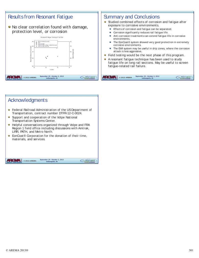
Results from Resonant Fatigue
No clear correlation found with damage, protection level, or corrosion
© 2013 AREMASeptember 29 – October 2, 2013
Indianapolis, IN
Summary and ConclusionsStudied combined effects of corrosion and fatigue after exposure to corrosive environments.
Effects of corrosion and fatigue can be separated.Corrosion significantly reduces rail fatigue life.Anti-corrosion treatments can extend fatigue life in corrosive environments. The EonCoat® system showed very good protection in extremely corrosive environments. The EWI system may be useful in drip zones, where the corrosion attack is less aggressive.
Field testing would be the next phase of this program. A resonant fatigue technique has been used to study fatigue life on long rail sections. May be useful to screen fatigue-related rail failure.
© 2013 AREMA
September 29 – October 2, 2013Indianapolis, IN
Acknowledgments
Federal Railroad Administration of the US Department of Transportation, contract number DTFR-12-C-0024. Support and cooperation of the Volpe National Transportation Systems Center. Helpful conversations organized through Volpe and FRA Region 1 field office including discussions with Amtrak, LIRR, PATH, and Metro North. EonCoat® Corporation for the donation of their time, materials, and services.
© 2013 AREMA
© AREMA 2013® 301


![An Investigation of the Fatigue Corrosion Behavior of Al ...jefm.kiau.ac.ir/article_532834_35ec4c96660ce2411ec1538bc611f3e… · decrease of fatigue corrosion of this alloy [25-27]](https://img.dokumen.tips/doc/110x75/5fc687c48f38ba50701bbe44/an-investigation-of-the-fatigue-corrosion-behavior-of-al-jefmkiauacirarticle53283435ec4c96660ce2411ec1538bc611f3e.jpg)