Embed Size (px)
Citation preview
CHINESE JOURNAL OF MECHANICAL ENGINEERING Vol. 27, No. 1, 2014 ·103·
DOI: 10.3901/CJME.2014.01.103, available online at www.springerlink.com; www.cjmenet.com; www.cjmenet.com.cn
Effects of Chip Geometries on Dielectrophoresis and Electrorotation Investigation
REN Yukun1, 2, *, WU Hongchi3, FENG Guojing1, HOU Likai1, and JIANG Hongyuan1
1 School of Mechatronics Engineering, Harbin Institute of Technology, Harbin 150001, China 2 State Key Laboratory of Fluid Power Transmission and Control, Zhejiang University, Hangzhou 310027, China
3 The First Affiliated Hospital, Harbin Medical University, Harbin 150081, China
Received March 9, 2013; revised October 9, 2013; accepted November 12, 2013
Abstract: The electric fields employed for such work are generated using chips, such as planar linear interdigitated arrays or two parallel arrays. However, chip geometries usually affect the investigation of dielectrophoresis (DEP) and electrorotation (ER) significantly, and even may misdirect the theoretical prediction. In order to understand the electrodes geometries effect and provide a suitable range of parameters, three-dimensional simulations for the DEP and ER characterizations on the quadrupolar hyperbolical electrodes are carried out. Influences of the electrodes gaps, cell height, work region, energized voltage and frequencies for the DEP and ER manipulations are analyzed, and the analysis results show that the gaps of the electrodes and the cell height have enormous effects, but the work region is not so important. Moreover, depending on the theoretical analysis, ER experiments for polystyrene microspheres with the diameter of 20 µm are carried out on two kinds of chips. The experimental results show that the microspheres rotate in the counter-field direction and the maximum rotation speed appears in the megahertz range. In addition, the experimental results are compared with the simulation results, showing that the three-dimensional simulations considering the chip geometries are more accurate than the two-dimensional predictions. This paper provides a new understanding for the theoretical predictions of DEP and ER manipulations, which decreases the difference of the theoretical and experimental results significantly, and will be significant for the lab chip research. Keywords: dielectrophoresis, electrorotation, chip geometries 1 Introduction∗
Microfluidics deals with the behavior, control and manipulation of microscopic particles and fluids that are geometrically constrained to the submillimeter scale[1–2]. The physics of fluids at this scale has been long of interest in colloids and life sciences. Currently, Microfluidics is a broader term that also includes all the technological research focused on the microfabrication techniques of microfluidic circuits, as part of a more general engineering field known as micro-electro-mechanical systems (MEMS) [3]. The reason for a fast increasing interest in this field is twofold: At first, fabrication techniques developed by the microelectronics industry allow accurate design of microfluidic circuits. Secondly, advances in biology and biotechnology require manipulation of particles or living cells.
Control of micrometer and nanometer sized objects is crucial for the development of new microfluidics-based technologies like the Lab-on-a-chip and micro-Total
* Corresponding author. E-mail: [email protected] This project is supported by National Natural Science Foundation of
China (Grant No. 51305106) and The State Key Lab of Fluid Power Transmission and Control of Zhejiang University, China (Grant No. GZKF-201107) © Chinese Mechanical Engineering Society and Springer-Verlag Berlin Heidelberg 2014
Analysis microsystem ( TASµ )[4–5]. The use of electric fields is a promising way of achieving this control: electrodes are easily integrated in microdevices by current microfabrication techniques and the importance of electrical forces over other forces is favored by scaling down the typical dimension of the devices. Therefore, much interest is now been taking in investigating the possibilities of electric fields in microsystems[6–7].
Electrical manipulation of microparticles is rapidly becoming a major area of research, with particular application in biotechnology and biochemistry[8]. Dielectrophoresis (DEP) and electrorotation (ER) are typical electrokinetic methods, which describe the motion of dielectrically polarized materials in non-uniform electric fields and have many applications in biotechnology, such as separation, detection, and characterization of cells[9–11].
In the traditional work on the DEP and ER, theoretical prediction of the electric field and gradients of the square of the electric field was expected to compare with the experimental results, which is crucial to certificate theory and direct experiments. However, many estimates of these values were achieved only using two dimensional simulation or even calculated by Vd (V is the voltage energized on the electrode, and d is the distance of the electrodes) directly. If these values were only utilized to estimate the tendency, the inaccuracy effect was less. But
REN Yukun, et al: Effects of Chip Geometries on Dielectrophoresis and Electrorotation Investigation
·104·
for a parameter to calculate other values, these data are still needed to be considered carefully. For instance, in order to determine the Clausius-Mossotti factors and surface capacitances for colloidal particles using combined electroosmosis and DEP[12], a new research selected the two dimensional computed values of the gradient of square of electric field as a parameter, to calculate the desired values. Obviously, this step is not so accurately, because the authors did not consider the size of the cell and also the length of the electrodes, which lead to a five times larger of this value compared with the three dimensional simulation. Therefore, electrodes and the cell geometries for the DEP and ER research are important, especially for the calculated results, which motivate our work on this paper.
In this paper, hyperbolical quadrupolar electrodes, and the typical geometry for DEP and ER, were investigated. Firstly, the DEP and ER theory was introduced and the key parameters affected by the geometry obviously were analyzed. Secondly, three dimensional model of this kind of electrodes with different distance was set sup and the electric field and gradient of the square of electric field were both calculated against different electrodes geometries. Thirdly, experimental results for microsphere were compared with two and three dimensional simulation results, respectively. Finally, a table for the reference values of hyperbolical quadrupolar electrodes was presented.
2 Dielectrophoresis and Electrorotation
Dielectrophoresis is the force induced on a polarizable
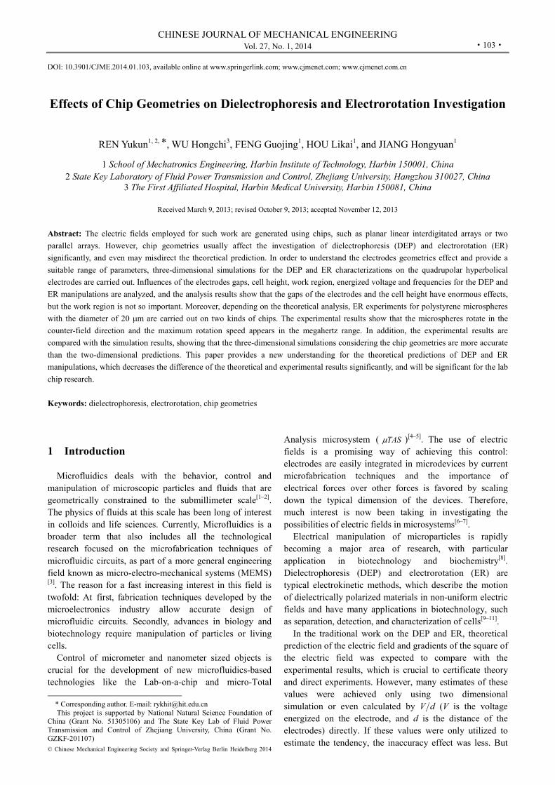
particle suspended in a nonuniform electric field[13]. In a nonuniform electric field showed in Fig. 1[6], the spherical particle and medium are polarized and produce net charges at its interface. If the polarisability of the particle is much lower than the electrolyte, there will be more charges outside the interface than inside. So the direction of the induced dipole is against the field as shown in the figure. The net induced dipole can be calculated by
p m 3m
p mπ,
2v a
ε εα ε
ε εp E E
4 (1)
where p —Net induced dipole,
v —Volume of particles, E —Electric field vector,
mε —Medium permittivity, pε —Particle permittivity,
α —Polarisability, a —Particles radius, ~ —Complex expression.
And we define the Clausius-Mossotti factor as
p mCM p m
p m
( ) ( )( , ) ( ) .
( ) 2 ( )f K
ε ω ε ωε ε ω
ε ω ε ω
(2)
The complex expression can be rewritten in the equation that ( ) j ,ε ω ε σ ω j 1, ω is the frequency of the electric field [13].
Fig. 1. Schematic diagram of the generation of the dipole and
DEP force in the nonuniform electric field
Furthermore, in Fig. 1, for the electric field is
nonuniform and the directions of the induced dipole and the electric field are opposite, the sphere endures a negative force directing to the side which has the weaker field.
In an AC harmonic electric field, the potential can be defined as ( , ) Re[ ( ) exp(i )]t tφ φ ωx x and the electric field is then given by ( , ) Re[ ( ) exp(i )],t tωE x E x where R Ii ,φ φ φ R I( i ).φ φ φE And the effective dipole is rewritten as
3exp(i ) 4 ( ) exp(i ).v E t K a E tα ω ω ωπ p (3)
According to the well known expression for the force on the dipole[6] DEP ( ) , F p E (4)
the force in the AC harmonic electric field changes to DEP Re[ exp(i )] Re[ exp(i )].t tω ω F p E (5)
And the time-average dielectrophoretic force can be written in the flowing equation
DEP
3m
3m
1( ) Re ( )2
1 Re ( ) exp(i ) )2
2 Re ( ) ( ) ,
t
K a t
K a
ε ω ω
ε ω
π
π
F p E
E E
E E
(4 (6)
where E is the complex conjugation of E. Using the regulation of vector differential operation
( A B A B B A B A A B ) ( ) ( ) ( ) ( )and the facts that the electric field is irrotational
0E and has zero divergence 0 E (Gauss’s law) in a homogeneous dielectric, we
acquired 2rms) , E E E( where rmsE is the
root-mean-square (rms) value *E E and the relationship
between rmsE and E is rms 2 .E E
Therefore, the force expression becomes

CHINESE JOURNAL OF MECHANICAL ENGINEERING
·105·
23DEP m rms
23m
2 Re ( ) Re ( ) .
r Kr K
ε ωε ω
ππ
F EE
(7)
Depending on Eq. (2) and Eq. (5), we can see that the
magnitude of the DEP force is concerned with the volume of the particle, the permittivity of the suspending medium, the real part of the CM factor and the gradient of the squared field strength. And the DEP force is positive or negative, depending on whether the polarization of particles is more or less than medium.
If the electric field strength E changes not only its magnitude, but also its vector direction, the particles in the field would produce electrorotation.
When the signals applied to the four electrodes of the hyperbolical quadrupolar electrodes differ 90°, a rotation field is generated in the space among the electrodes and the particle’s dipole moment vector includes an angleθ with the direction of E shown in Fig. 2[6].
Fig. 2. Schematic diagram of the electric field
and dipole moment vectors
So the dipole moment vector must rearrange itself with
the electric field vector, causing particle rotation. And the torque is given by[6–7]
*ROT
* * *
1 1Re Re ,2 2 x y z
x y z
p p p
E E E
Γ
x y zp E (8)
where we assume the electric field is a right circularly polarized vector of magnitude E0 0 ( i ).EE x y (9)
Its conjugate matrices is
*0 ( i ).EE x y (10)
According to Eq. (3),
3x m 04 ( ) ,p a K Eε ωπ (11)
3
y m 0i4 ( ) .p a K Eε ωπ (12)
Substituting px, py, Ex, Ey to Eq. (6), then we arrived at
3 2 3 2m 0 m
ROT 0 0*
0
*
1 1Re 0 Re (i )2
Re i ( ) 4 ( )
20
4 Im
x y x y
x y
p p p E
a K E a
p E
EK E
Eε ω ε ωππ
y zz
z
xΓ
(13) Eq. (13) shows that the coefficient of determination of
the magnitude of ER torque is also the volume of the particle, the permittivity of the suspending medium, the imaginary part of CM factor and the squared field strength.
While for the special particle and suspending medium, the electric field strength determines for the force and torque. So it is necessary to do researches on the DEP and ER, we can make studies on the squared gradient of the field strength ( 2E ) and the field strength magnitude ( E0 ).
3 Three-dimensional Model Set Up
The Comsol 4.2 was used to find the potential in the
three dimensional domains of Fig. 3 for both DEP and ER experiments.
Fig. 3. Schematic diagrams of the simulation models
In Fig. 3, parameter d is the opposite distance of the
electrodes, h is the height of the cell. Equation of the hyperbolic electrodes curve should be written as[6]
2
,8
dxy (14)
where x and y are the coordinates. In order to obtain this equation in Comsol, a basic function associated with parameter t was set in Eq. (15):
2
2
sec ,2 ,
2 2tan ,2
dx tt
dy t
π π
(15)
where t is the parameter of the hyperbolic curve which affects the length of the electrode s(t). In fact, the curve drew using Eq. (15) has the same shape as Eq. (14), but not the same coordinate. Therefore, the shape obtained by Eq. (15) in Comsol should be rotated for 45°, 135°, 225° and 315°, respectively, in four quadrants.
字号 10 磅
REN Yukun, et al: Effects of Chip Geometries on Dielectrophoresis and Electrorotation Investigation
·106·
The electric potential in the liquid can be written as
Re[ exp(i )],tφ ω Φ (16)
where φ is the electric potential phasor, and it is the solution of Laplace equation with specific boundary conditions, where the Laplace equation can be expressed as
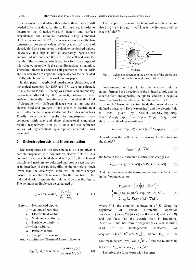
2 0. Φ (17) The boundary conditions for DEP and ER are shown in
Fig. 4. As Fig. 4 shows, at the bottom glass and the side and top walls, the boundary condition is zero normal current, which means, 0,n j (18)
where n is a unit vector normal to the boundary, and j is the current, which obeys the Ohm’s law, i.e., .σj E This condition transforms into 0, n Φ (19)
which means the derivative of the electric potential is zero.
The boundary conditions at the electrodes depend on the energized signal. For the DEP experiments, each electrode is subjected to an AC signal of amplitude V0 and the phase difference between adjacent electrodes is 180°. The boundary conditions for the electric potential phasor are either V0 for the electrodes at phase 0° or V0 for the electrodes at phase 180°, as Fig. 4(a) shows.
Fig. 4. Boundary conditions
For electrorotation, the energized signals of every
electrode have 90° difference, as Fig. 4(b) shows. The signal with the phase of zero can be written as
1 0 c( ) os( ).V t V tω (20)
So the followed electrodes should be expressed as follows:
2 0 0π( ) cos sin( ),2
V t V t V tω ω
(21)
3 0( ) cos( ),V t V tω π (22)
4 03π( ) cos .2
V t V tω
(23)
In order to sort above expressions, we have
exp(i ) cos i sin ,ϕ ϕ ϕ (24)
cos Re exp(i ) ,ϕ ϕ (25) and then
2 0 0
0
0
0 0
( ) sin( ) cos2
Re exp i2
Re cos i sin exp(i )2 2
Re i exp(i ) i .
V t V t V t
V t
V t
V t V
ω ω
ω
ω
ω
π
π
π π
(26)
Similarly, the others are expressed as follows:
3 0 0( ) cos( ) ,V t V t Vω π (27)
4 0 0
3π( ) cos i .2
V t V t Vω
(28)
Therefore, the boundary conditions for the electric
potential phasor are V0, iV0, V0, and iV0, as Fig. 4(b) shown. 4 Results and Discussions
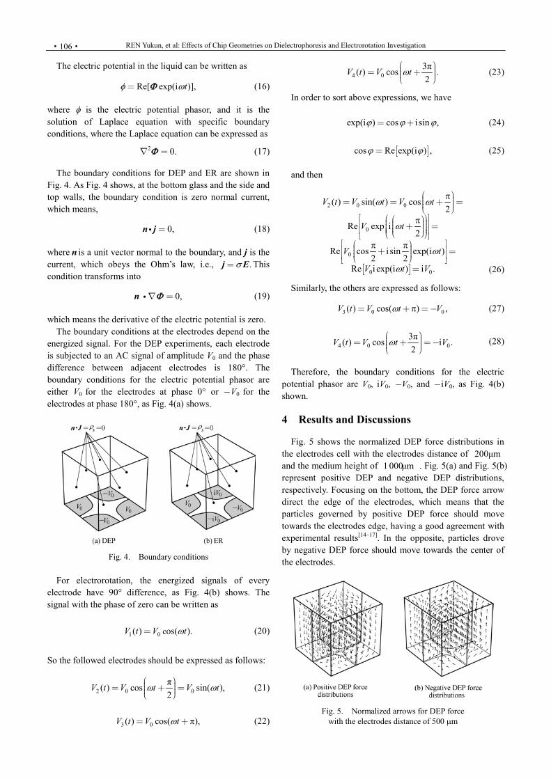
Fig. 5 shows the normalized DEP force distributions in
the electrodes cell with the electrodes distance of 200μm and the medium height of 1 000μm . Fig. 5(a) and Fig. 5(b) represent positive DEP and negative DEP distributions, respectively. Focusing on the bottom, the DEP force arrow direct the edge of the electrodes, which means that the particles governed by positive DEP force should move towards the electrodes edge, having a good agreement with experimental results[14–17]. In the opposite, particles drove by negative DEP force should move towards the center of the electrodes.
Fig. 5. Normalized arrows for DEP force
with the electrodes distance of 500 µm
CHINESE JOURNAL OF MECHANICAL ENGINEERING
·107·
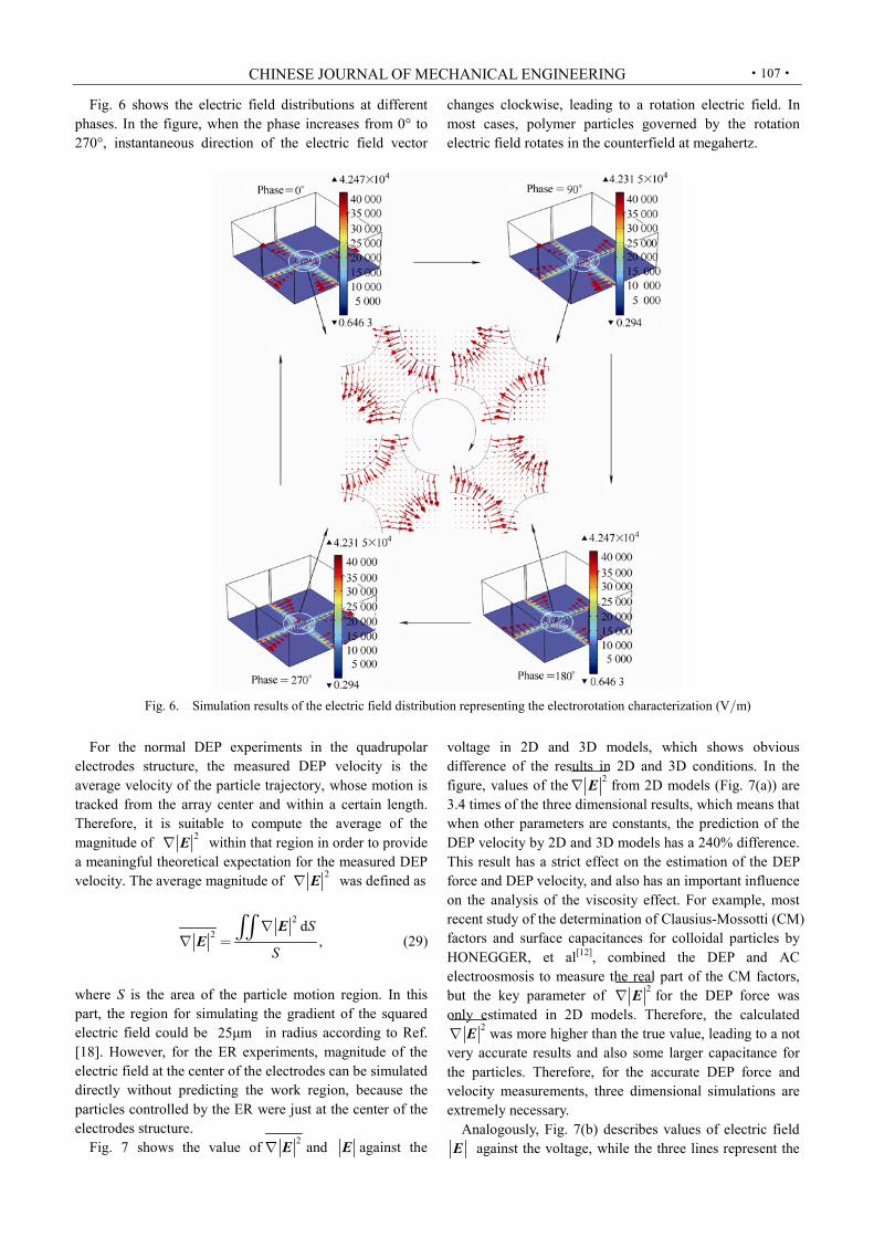
Fig. 6 shows the electric field distributions at different phases. In the figure, when the phase increases from 0° to 270°, instantaneous direction of the electric field vector
changes clockwise, leading to a rotation electric field. In most cases, polymer particles governed by the rotation electric field rotates in the counterfield at megahertz.
Fig. 6. Simulation results of the electric field distribution representing the electrorotation characterization (Vm)
For the normal DEP experiments in the quadrupolar
electrodes structure, the measured DEP velocity is the average velocity of the particle trajectory, whose motion is tracked from the array center and within a certain length. Therefore, it is suitable to compute the average of the magnitude of 2E within that region in order to provide a meaningful theoretical expectation for the measured DEP velocity. The average magnitude of 2E was defined as
22
d,
S
S
EE
(29)
where S is the area of the particle motion region. In this part, the region for simulating the gradient of the squared electric field could be 25μm in radius according to Ref. [18]. However, for the ER experiments, magnitude of the electric field at the center of the electrodes can be simulated directly without predicting the work region, because the particles controlled by the ER were just at the center of the electrodes structure.
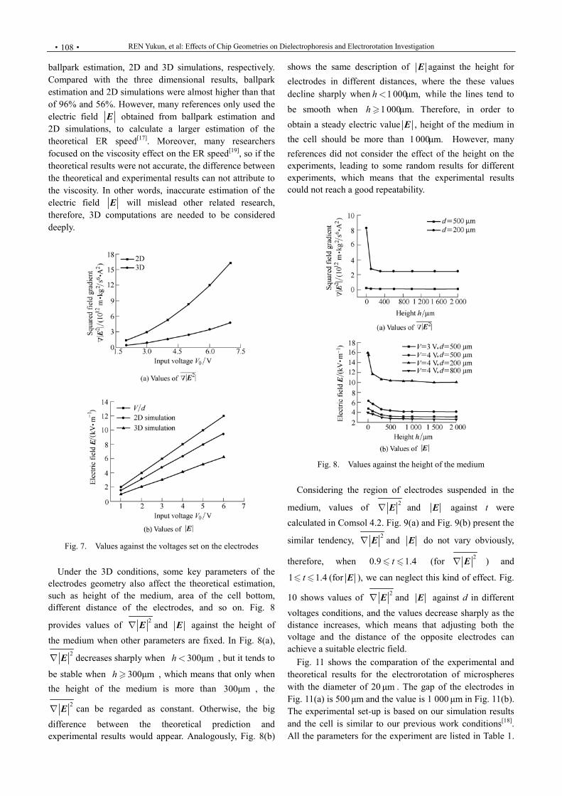
Fig. 7 shows the value of 2E and E against the
voltage in 2D and 3D models, which shows obvious difference of the results in 2D and 3D conditions. In the figure, values of the 2E from 2D models (Fig. 7(a)) are 3.4 times of the three dimensional results, which means that when other parameters are constants, the prediction of the DEP velocity by 2D and 3D models has a 240% difference. This result has a strict effect on the estimation of the DEP force and DEP velocity, and also has an important influence on the analysis of the viscosity effect. For example, most recent study of the determination of Clausius-Mossotti (CM) factors and surface capacitances for colloidal particles by HONEGGER, et al[12], combined the DEP and AC electroosmosis to measure the real part of the CM factors, but the key parameter of 2E for the DEP force was only estimated in 2D models. Therefore, the calculated
2E was more higher than the true value, leading to a not very accurate results and also some larger capacitance for the particles. Therefore, for the accurate DEP force and velocity measurements, three dimensional simulations are extremely necessary.
Analogously, Fig. 7(b) describes values of electric field E against the voltage, while the three lines represent the
REN Yukun, et al: Effects of Chip Geometries on Dielectrophoresis and Electrorotation Investigation
·108·
ballpark estimation, 2D and 3D simulations, respectively. Compared with the three dimensional results, ballpark estimation and 2D simulations were almost higher than that of 96% and 56%. However, many references only used the electric field E obtained from ballpark estimation and 2D simulations, to calculate a larger estimation of the theoretical ER speed[17]. Moreover, many researchers focused on the viscosity effect on the ER speed[19], so if the theoretical results were not accurate, the difference between the theoretical and experimental results can not attribute to the viscosity. In other words, inaccurate estimation of the electric field E will mislead other related research, therefore, 3D computations are needed to be considered deeply.
Fig. 7. Values against the voltages set on the electrodes
Under the 3D conditions, some key parameters of the
electrodes geometry also affect the theoretical estimation, such as height of the medium, area of the cell bottom, different distance of the electrodes, and so on. Fig. 8
provides values of 2E and E against the height of the medium when other parameters are fixed. In Fig. 8(a),
2E decreases sharply when 300μmh , but it tends to
be stable when 300μmh , which means that only when the height of the medium is more than 300μm , the
2E can be regarded as constant. Otherwise, the big difference between the theoretical prediction and experimental results would appear. Analogously, Fig. 8(b)
shows the same description of E against the height for electrodes in different distances, where the these values decline sharply when 1 000μm,h while the lines tend to be smooth when 1 000μm.h Therefore, in order to obtain a steady electric value E , height of the medium in the cell should be more than 1 000μm. However, many references did not consider the effect of the height on the experiments, leading to some random results for different experiments, which means that the experimental results could not reach a good repeatability.
Fig. 8. Values against the height of the medium
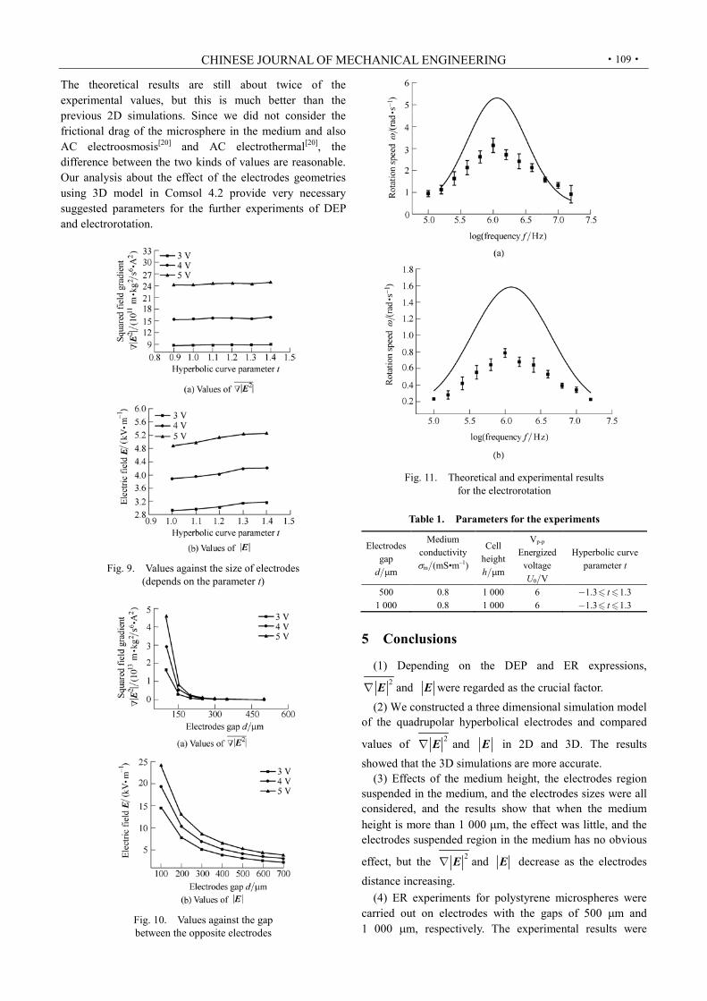
Considering the region of electrodes suspended in the
medium, values of 2E and E against t were calculated in Comsol 4.2. Fig. 9(a) and Fig. 9(b) present the
similar tendency, 2E and E do not vary obviously,
therefore, when 0.9 1.4t (for 2E ) and
1 1.4t (for E ), we can neglect this kind of effect. Fig.
10 shows values of 2E and E against d in different voltages conditions, and the values decrease sharply as the distance increases, which means that adjusting both the voltage and the distance of the opposite electrodes can achieve a suitable electric field.
Fig. 11 shows the comparation of the experimental and theoretical results for the electrorotation of microspheres with the diameter of 20 μm . The gap of the electrodes in Fig. 11(a) is 500 μm and the value is 1 000 μm in Fig. 11(b). The experimental set-up is based on our simulation results and the cell is similar to our previous work conditions[18]. All the parameters for the experiment are listed in Table 1.
CHINESE JOURNAL OF MECHANICAL ENGINEERING
·109·
The theoretical results are still about twice of the experimental values, but this is much better than the previous 2D simulations. Since we did not consider the frictional drag of the microsphere in the medium and also AC electroosmosis[20] and AC electrothermal[20], the difference between the two kinds of values are reasonable. Our analysis about the effect of the electrodes geometries using 3D model in Comsol 4.2 provide very necessary suggested parameters for the further experiments of DEP and electrorotation.
Fig. 9. Values against the size of electrodes
(depends on the parameter t)
Fig. 10. Values against the gap between the opposite electrodes
Fig. 11. Theoretical and experimental results
for the electrorotation
Table 1. Parameters for the experiments
Electrodes gap
dµm
Medium conductivity σm(mS•m–1)
Cell height hµm
Vp-p Energized
voltage U0V
Hyperbolic curve parameter t
500 0.8 1 000 6 1.3 1.3t 1 000 0.8 1 000 6 1.3 1.3t
5 Conclusions
(1) Depending on the DEP and ER expressions,
2E and E were regarded as the crucial factor. (2) We constructed a three dimensional simulation model
of the quadrupolar hyperbolical electrodes and compared
values of 2E and E in 2D and 3D. The results showed that the 3D simulations are more accurate.
(3) Effects of the medium height, the electrodes region suspended in the medium, and the electrodes sizes were all considered, and the results show that when the medium height is more than 1 000 µm, the effect was little, and the electrodes suspended region in the medium has no obvious
effect, but the 2E and E decrease as the electrodes distance increasing.
(4) ER experiments for polystyrene microspheres were carried out on electrodes with the gaps of 500 µm and 1 000 µm, respectively. The experimental results were

REN Yukun, et al: Effects of Chip Geometries on Dielectrophoresis and Electrorotation Investigation
·110·
compared with the 3D simulation results with proper settings in Table 1, showing that the difference of the two kinds of values was obviously less than the 2D results. Therefore, this research about the effect of the electrodes geometry decreases the difference gap of the theoretical and experimental results, leading to a more accurate simulation prediction.
References [1] STONE H A, STROOCK A D, AJDARI A. Engineering flows in
small devices: microfluidics toward a Lab-on-a-Chip[J]. Annual Review of Fluid Mechanics, 2004, 36(7): 381–411.
[2] SQUIRES T M, QUAKE S R. Microfluidics: fluid physics at the nanoliter scale[J]. Review of Modern Physics, 2005, 77(3): 977– 1 026.
[3] MALOUF N, WILLIAMS K. An introduction to microelectromechanical systems engineering[M]. Boston: Artech House, 2004.
[4] WHITESIDES G M, JANASEK D, FRANZKE J. Insight: Lab on a chip[J]. Nature, 2006, 442(7101): 367–418.
[5] DITTRICH PS, TACHIKAWA K, MANZ A. Micro total analysis systems. Latest advancements and trends[J]. Analytical Chemistry, 2006, 78(12): 3 887–3 908.
[6] MORGAN H, GREEN N G. AC Electrokinetics: colloids and nanoparticles[M]. Baldock: Research Studies Press, 2003.
[7] RAMOS A. Electrokinetics and electrohydrodynamics in microsystems[M]. New York: Springer, 2011.
[8] POHL H A. The motion and precipitation of suspensoids in divergent electric fields[J]. Journal of Applied Physics, 1951, 22(7): 869–871.
[9] PETHIG R. Dielectrophoresis: using inhomogeneous AC electrical fields to separate and manipulate cells[J]. Critical Reviews in Biotechnology, 1996, 16(4): 331–348.
[10] PETHIG R. Review article—dielectrophoresis: status of the theory, technology, and applications[J]. Biomicrofluidics, 2010, 4(2): 022811.
[11] JIANG H Y, REN Y K, AO H R, et al. Electrohydromechanical analysis based on conductivity gradient in microchannel[J]. Chinese Physics B, 2008, 17(12): 4 541–4 546.
[12] HONEGGER T, BERTON K, PICARD E, et al. Determination ofClausius-Mossotti factors and surface capacitances for colloidal particles[J]. Applied Physics Letters, 2011, 98(18): 181906.
[13] JONES T B. Electromechanics of particles[M]. Cambridge: Cambridge University Press, 1995.
[14] REN Y K, AO H R, GU J Z, et al. Research of micro-particle manipulation in micro systems using DEP force[J]. Acta Physica
Sinica, 2009, 58(11): 7 869–7 877. (in Chinese) [15] GREEN N G, MORGAN H. Dielectrophoresis of submicrometer
latex spheres 1: experimental results[J]. The Journal of Physical Chemistry B, 1999, 103(1): 41–50.
[16] GREEN N G, MORGAN H. Dielectrophoretic separation of nano-particles[J]. Journal of Physics D: Applied Physics, 1997, 30(11): 2 626–2 633.
[17] MORGANTI D, MORGAN H. Characterization of non-spherical polymer particles by combined electrorotation and electroorientation[J]. Colloids and Surfaces A: Physicochemical and Engineering Aspects, 2011, 376(1–3): 67–71.
[18] REN Y K, MORGANTI D, JIANG H Y, et al. Electrorotation of metallic microspheres[J]. Langmuir, 2011, 27(6): 2 128–2 131.
[19] LEI U, YANG C Y, WU K C. Viscous torque on a sphere under arbitrary rotation[J]. Applied Physics Letters, 2006, 89(18): 181908.
[20] RAMOS A, MORGAN H, GREEN N G, et al. AC electrokinetics: a review of forces in microelectrode structures[J]. Journal of Physics D: Applied Physics, 1998, 31(18): 2 338–2 353.
Biographical notes REN Yukun, born in 1981, is currently a lecture at School of Mechanical Engineering, Harbin Institute of Technology, China. The interest topic is microfluidics. Tel: +86-451-86418028; E-mail: [email protected] WU Hongchi, born in 1962, is currently a professor at First Affiliated Hospital, Harbin Medical University, China. Her main research interest is kidney disease clinical molecular biology research. E-mail: [email protected] FENG Guojing, born in 1987, is currently a master candidate at School of Mechanical Engineering, Harbin Institute of Technology. HOU Likai, born in 1987, is currently a master candidate at School of Mechanical Engineering, Harbin Institute of Technology, China. E-mail: [email protected] JIANG Hongyuan, born in 1960, is currently a professor and a PhD candidate supervisor at School of Mechanical Engineering, Harbin Institute of Technology, China. His main research interests include metal rubber, microfluidics, etc. E-mail: [email protected]