Embed Size (px)
Citation preview
International Journal Of Scientific & Engineering Research Volume 2, Issue 9, September-2011 1
ISSN 2229-5518
IJSER © 2011
http://www.ijser.org
Effect on Strength of Involute Spur Gear by Changing the Fillet Radius Using FEA
Ashwini Joshi, Vijay Kumar Karma
Abstract—Gearing is the special division of Mechanical Engineering concerned with the transmission of power and motion between the rotating shafts.
Gears not only transmit motion and enormous power satisfactorily, but can do so with very uniform motion. It is the best and the economical means of achieving this transmission. Gear teeth fails due to the static and the dynamic loads acting over it, also the contact between the two meting gears causes the surface failures. The gear fails without any warning and the results due to this failure are catastrophic. Since the requirements are broad and are of varying difficulty, gearing is a complex and diversified field of engineering. It includes gear mathematics, geometrical design, strength and wear, material and metallurgy, fabrication and inspection. Therefore for all the reasons mentioned, this work is of more practical importance. To get the gear of more durability we can use improved material, hardening the gear surfaces with heat treatment and carburization, shot penning can be done to improve the surface finish, to change the pressure angle by using asymmetric teeth, introducing the stress relieving features of different shape, changing the adden-dum of the spur gear and altering the design of root fillet are the other methods.Present work deals with the effect on gear strength with variation of root fillet design using FEA. Circular root fillet design is considered for analysis. The loading is done at the highest point of single tooth contact (HPSTC).
Index Terms— Gear Design, Gear Strength, Fillet Radius, Circular Fillet, Trochoidal Fillet, Pro/ENGINEER, Pro/MECHANICA, Deflection.
—————————— ——————————
INTRODUCTION
ears are usually used in the transmission system is also
called a speed reducer, which consists of a set of gears,
shafts and bearings that are factory mounted in an enclosed
lubricated housing. Speed reducers are available in a broad
range of sizes, capacities and speed ratios.
Wilfred Lewis developed the basic model for bending stress
in gear teeth in 1892. In his analysis, Lewis considered a gear
tooth to be a loaded cantilever beam with a force applied to
the tip of the gear. He made the following assumptions;
1. The load is applied to the tip of a gear tooth;
2. Only the tangential component of the force will be a fac-
tor (the radial component is neglected);
3. The load is distributed uniformly across the entire face
width of the gear;
4. Forces due to tooth sliding friction are negligible; and
5. No stress concentration is present in the tooth fillet. [1] A pair of teeth in action is generally subjected to two types
of cyclic stresses: bending stresses inducing bending fatigue and contact stress causing contact fatigue. Both these types of stresses may not attain their maximum values at the same point of contact. However, combined action of both of them is the reason of failure of gear tooth leading to fracture at the root of a tooth under bending fatigue and surface failure, like pitting or flaking due to contact fatigue.
These types of failures can be minimized by careful
analysis of the problem during the design stage and creating
proper tooth surface profile with proper manufacturing me-
thods.
The finite element method is capable of providing this
information, but the time needed to create such a model is
large. In order to reduce the modeling time, a preprocessor
method that creates the geometry needed for a finite element
analysis may be used, such as that provided by Pro Engineer-
ing. It can generate models of three-dimensional gears easily.
The finite element method is very often used to analyze the
stresses in an elastic body with complicated geometry, such as
a gear.
In this work the effect on strength of involute spur gear
with change in the design of root fillet radius is studied. The
gear is modelled with circular fillet and then finite element
analysis is carried out by taking the load at the highest point
of the single tooth contact using Pro/ENGINEER wildfire
software. The maximum and the minimum distortion pro-
duced at the fillet by both type of the loading are compared.
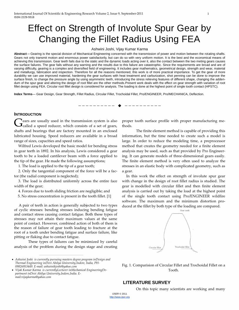
Fig. 1. Comparision of Circular Fillet and Trochoidal Fillet on a
Tooth.
LITERATURE SURVEY
On this topic many scientists are working and many
G
————————————————
Ashwini Joshi is currently pursuing masters degree program inDesign and Thermal Engineering inDevi Ahilya University,Indore, India, PH-09826953449. E-mail: [email protected]
Vijak Kumar Karma is currentlyLecturer inMechanical EngineeringDe-partment inDevi Ahilya University,Indore,India. E-mail:[email protected]
International Journal of Scientific & Engineering Research Volume 2, Issue 9, September-2011 2
ISSN 2229-5518
IJSER © 2011
http://www.ijser.org
of them find methods to increase the strength of the gear. Some technical papers published in the field related to the topic. Christos A. Spitas and Vasilis A. Spitas [2] did his work on a new spur gear 200 design that works interchangeably with standard 200 system and achieves increased tooth bend-ing strength and hence the load carrying capacity. In this de-sign, circular fillet replaces the normal trochoidal fillet, yield-ing large cross sectional at the tooth root and lower stress con-centration. V. Spitas, Th. Costopoulos and C. Spitas [3] did his work on spur gear teeth with circular instead of the standard trochoidal root fillet is introduced and investigated numerical-ly using FEA. M. Savage and Rubadeux [4] has propose a bending strength model for internal spur gear teeth, this mod-el assist design efforts for unequal addendum gears and gears of mixed materials. M Koilraj, Dr G Muthuveerappan and Dr. J. Pattabiraman [5] on the basis of their work gives the conclu-sion that, the stress correction factor and the form factor in-creases with the increase in positive profile correction.
MODELLING OF GEAR
In total 15 number of gears are modelled in
Pro/ENGINEER Wildfire [6], which are having the following
parameters.
Module 5mm; Three set of gears having number of teeth 14,18
and 30; Each set of gear having pitch circle diameter 70mm,
90mm, and 150mm; Radius of circular fillet for each set of gear
0.5mm, 1mm, 1.5mm, 2mm, 2.25mm; Pressure angle 200; Load
at highest point of single tooth contact 100kN; Gear Material fe
20. The following steps are showing the procedure to model
the gear of 18 number of teeth with the combination of the all
above mentioned parameters in the Pro/ENGINEER Wildfire,
other set of gears are modelled in the similar way.
Part parameters are the basic parameters defining the gear.
These part parameters determine all the other parameters that
define the gear tooth profile by using the Tools/Relation menu.
Figure 2 showing the part parameters.
Fig. 2. Part Parameters
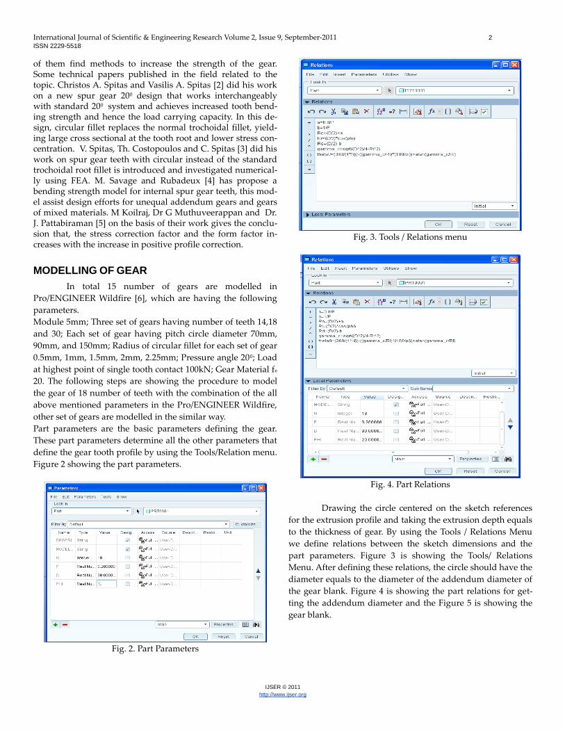
Fig. 3. Tools / Relations menu
Fig. 4. Part Relations
Drawing the circle centered on the sketch references
for the extrusion profile and taking the extrusion depth equals
to the thickness of gear. By using the Tools / Relations Menu
we define relations between the sketch dimensions and the
part parameters. Figure 3 is showing the Tools/ Relations
Menu. After defining these relations, the circle should have the
diameter equals to the diameter of the addendum diameter of
the gear blank. Figure 4 is showing the part relations for get-
ting the addendum diameter and the Figure 5 is showing the
gear blank.
International Journal of Scientific & Engineering Research Volume 2, Issue 9, September-2011 3
ISSN 2229-5518
IJSER © 2011
http://www.ijser.org
Fig. 5. Gear Blank
Selecting From Equation from the Insert/ Model Datum/
Curve Menu. we take “PRT_CSYS_DEF” as a default coordi-
nate system. Taking coordinate system cylindrical type. In this
point a Notepad window will pop up where we can enter all
equations for the datum curve. As shown in the Figure 6 [7].
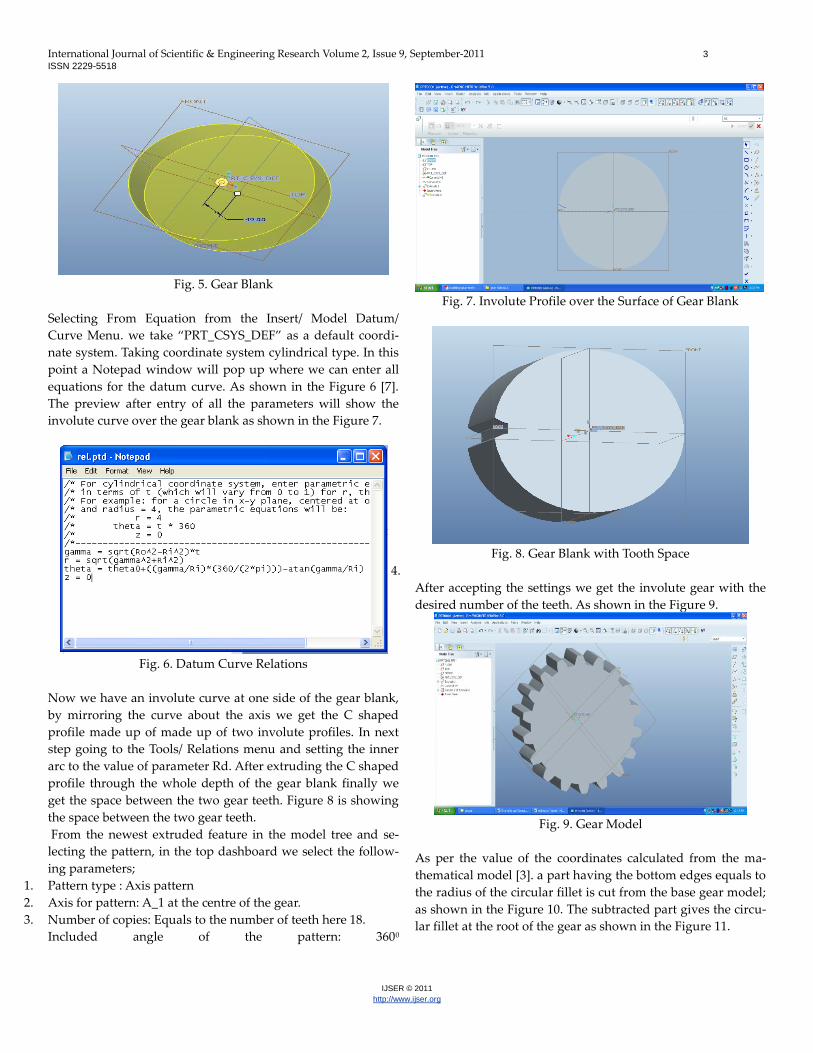
The preview after entry of all the parameters will show the
involute curve over the gear blank as shown in the Figure 7.
Fig. 6. Datum Curve Relations
Now we have an involute curve at one side of the gear blank,
by mirroring the curve about the axis we get the C shaped
profile made up of made up of two involute profiles. In next
step going to the Tools/ Relations menu and setting the inner
arc to the value of parameter Rd. After extruding the C shaped
profile through the whole depth of the gear blank finally we
get the space between the two gear teeth. Figure 8 is showing
the space between the two gear teeth.
From the newest extruded feature in the model tree and se-
lecting the pattern, in the top dashboard we select the follow-
ing parameters;
1. Pattern type : Axis pattern
2. Axis for pattern: A_1 at the centre of the gear.
3. Number of copies: Equals to the number of teeth here 18.
Included angle of the pattern: 3600
Fig. 7. Involute Profile over the Surface of Gear Blank
Fig. 8. Gear Blank with Tooth Space
4.
After accepting the settings we get the involute gear with the
desired number of the teeth. As shown in the Figure 9.
Fig. 9. Gear Model
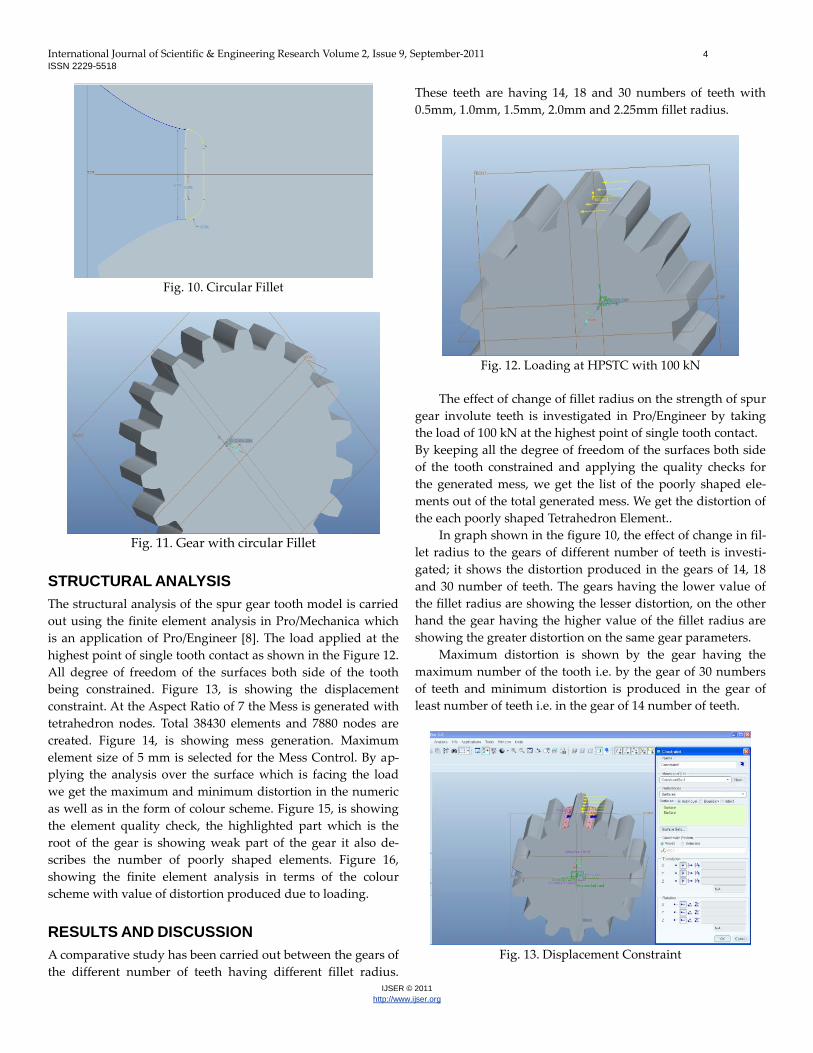
As per the value of the coordinates calculated from the ma-
thematical model [3]. a part having the bottom edges equals to
the radius of the circular fillet is cut from the base gear model;
as shown in the Figure 10. The subtracted part gives the circu-
lar fillet at the root of the gear as shown in the Figure 11.
International Journal of Scientific & Engineering Research Volume 2, Issue 9, September-2011 4
ISSN 2229-5518
IJSER © 2011
http://www.ijser.org
Fig. 10. Circular Fillet
Fig. 11. Gear with circular Fillet
STRUCTURAL ANALYSIS
The structural analysis of the spur gear tooth model is carried
out using the finite element analysis in Pro/Mechanica which
is an application of Pro/Engineer [8]. The load applied at the
highest point of single tooth contact as shown in the Figure 12.
All degree of freedom of the surfaces both side of the tooth
being constrained. Figure 13, is showing the displacement
constraint. At the Aspect Ratio of 7 the Mess is generated with
tetrahedron nodes. Total 38430 elements and 7880 nodes are
created. Figure 14, is showing mess generation. Maximum
element size of 5 mm is selected for the Mess Control. By ap-
plying the analysis over the surface which is facing the load
we get the maximum and minimum distortion in the numeric
as well as in the form of colour scheme. Figure 15, is showing
the element quality check, the highlighted part which is the
root of the gear is showing weak part of the gear it also de-
scribes the number of poorly shaped elements. Figure 16,
showing the finite element analysis in terms of the colour
scheme with value of distortion produced due to loading.
RESULTS AND DISCUSSION
A comparative study has been carried out between the gears of
the different number of teeth having different fillet radius.
These teeth are having 14, 18 and 30 numbers of teeth with
0.5mm, 1.0mm, 1.5mm, 2.0mm and 2.25mm fillet radius.
Fig. 12. Loading at HPSTC with 100 kN
The effect of change of fillet radius on the strength of spur
gear involute teeth is investigated in Pro/Engineer by taking
the load of 100 kN at the highest point of single tooth contact.
By keeping all the degree of freedom of the surfaces both side
of the tooth constrained and applying the quality checks for
the generated mess, we get the list of the poorly shaped ele-
ments out of the total generated mess. We get the distortion of
the each poorly shaped Tetrahedron Element..
In graph shown in the figure 10, the effect of change in fil-
let radius to the gears of different number of teeth is investi-
gated; it shows the distortion produced in the gears of 14, 18
and 30 number of teeth. The gears having the lower value of
the fillet radius are showing the lesser distortion, on the other
hand the gear having the higher value of the fillet radius are
showing the greater distortion on the same gear parameters.
Maximum distortion is shown by the gear having the
maximum number of the tooth i.e. by the gear of 30 numbers
of teeth and minimum distortion is produced in the gear of
least number of teeth i.e. in the gear of 14 number of teeth.
Fig. 13. Displacement Constraint

International Journal of Scientific & Engineering Research Volume 2, Issue 9, September-2011 5
ISSN 2229-5518
IJSER © 2011
http://www.ijser.org
CONCLUSION
The effect on the strength of spur involute gear by changing
the radius of the circular fillet was investigated. Gears of dif-
ferent parameters but having same module and pressure angle
was modelled and the distortion produced in the curvature
due to the loading at the highest point of single tooth contact
was analysed by using Finite Element Analysis.
Fig. 14. Mess Generation
Fig. 15. Element Quality Check
Fig. 16. Finite Element Analysis Result
From the analysis it is concluded that, as the fillet radius in-
creases from 0.5 mm to 1.5 mm the curvature deflection de-
creases and for the fillet radius 1.5 mm to 2.25 it increases with
the increase in the fillet radius in the gear of same number of
teeth.
Fig. 17. Graph Fillet radius Vs Curvature Deflection
It is also concluded that, the value of the deflection in the
curvature of the gear is more in the gear of more number of
teeth. Here the gear of 30 numbers of teeth is showing the
more deflection as compared to the gear of 18 numbers of
teeth. The gear with 14 numbers of teeth is showing the least
deflection in the gear curvature.
All the set of gears showing the least deflection for the fillet
radius of the 1.5 mm, hence we can say that the fillet radius of
1.5 mm is the optimum value of the fillet radius for the taken
set of the gears. At this value of the fillet radius the gears are
stronger then at the other fillet radius.
REFERENCES
[1]. V.B. Bhandari, “Design of Machine Elements”. pp. 522-575.
[2]. Christos A. Spitas and Vasilis A. Spitas, “Generating Interchange-
able 200 Spur Gear Sets with Circular Fillets to Increase Load Carry-
ing Capacity”, International Conference on Gears, Vol. I, VDI –
Verlag, Dusseldorf, Germany, July/August 2006, pp. 927-941.
[3]. V. Spitas, Th. Costopoulos and C. Spitas, “Increasing the Strength
of Standard Involute Gear Teeth with Novel Circular Root Fillet De-
sign”, American Journal of Applied Sciences, Science Publication
2005, pp. 1058-1064.
[4]. M.Savage , K.L. Rubadeux and H.H.Coe, “Bending Strength Mod-
el for Internal Spur Gear Teeth”, Army Research Laboratory
,Technical Memorandum San Diego, California, July 10-12, 1995.
[5]. M. Koilraj, Dr. G.Muthuveerappan, Dr. J. Pattabiraman, “An Im-
provement in Gear Teeth Methodology Using Finite Element Me-
thod”, IE Journal MC, Vol.88,Octomber 2007.
[6]. Pro/ENGINEER Wildfire 5.0
[7]. Mike Renfro, “Modeling Gear Teeth in Pro/Engineer Wildfire
4.0,2010.
[8]. Roger Toogood, “Pro/Mechanica Tutorial”. University of Ulberta.


![[1] involuteΣ(Spur and Helical Gear Design) 1.3 Software ...Eng).pdf · [1] involuteΣ(Spur and Helical Gear Design) 1 t Fig..1.1 Calculation Result Screen 1.1 Introduction involute](https://img.dokumen.tips/doc/110x75/5a7894b47f8b9a7b698d1836/1-involutespur-and-helical-gear-design-13-software-engpdf1-involutespur.jpg)