Embed Size (px)
Citation preview

International Journal of Mechanical & Mechatronics Engineering IJMME-IJENS Vol:18 No:01 8
181201-7575-IJMME-IJENS © February 2018 IJENS I J E N S
Effect of Winglet Vortex Generators Orientation on
Heat Transfer Enhancement Khudheyer S. Mushatet Iltifat lazim edan
Mech. Eng. Dept. Mech. Eng. Dept.
College of Engineering College of Engineering
Thi-Qar University Thi-Qar University
E-mail:[email protected] E-mail: el _la [email protected]
Abstract-- experimental; and numerical investigation of
three dimensional turbulent flow and heat transfer; inside a
rectangular channel equipped with array of winglet vortex
generators. Three pairs array of winglet vortex generators of
different geometrical configuration as rectangular , triangular
, semi circle and parabolic are considered. The array of winglet
vortex generators is formed and distributed on the bottom hot
surface with a facility for changing the angle of attack from (0°
to 60°). ANSYS Fluent C ode (15.0) based on a fi nite volume
method is used to obtain the numerical results while a k-
turbulence model is used to model the tur bulent .The Reynolds
number range is from 10000 to 50,000 under a constant heat
flux boundary condition.. Two cases of winglet vortex
generators array are included. The first case is anti stream
common flow up. The second case is the combined anti and
with stream common flow up. The two cases are tested for
different values of angle of attack, the stream wise and span
wise position between the vortex and Reynolds number. The
obtained results show that the suggested arrangement of
common ;flow up (anti and with stream) for vortex generator
offers superior in heat transfer enhancement and overall
thermal performance rated by 240% and 170% respectively.
In addition, A signification increase in heat transfer
enhancement , and overall thermal performance is found as the
angle of attack and the positions between vortex generator
increases .
Index Term— winglet vortex generators, turbulent channel
flow, CFD
1. INTRODUCTION
The vortex generators are considered as a kind of passive
heat transfer enhancement dev ices. This system is used for
thermal equipment such as heat exchanger and internal
cutting edge cooling of a gas tu rbine. The system o f heat
tran sfer enhancement is based o n fl ow part ition a nd
reattachment. In ge neral, flow reatt achment intro duces a
strong shear flow o n the sur face beh ind each winglet or rib,
resu lting in an effe ctive distur bance of the ther mal boundary
layer and in this way the heat transfer is improved [1]. A
vortex generator is usually a small triangular or rectangular
plate that is mounted on a surface at an angle to the
incoming flow. Experim ental investigate b y Feib ig et al. [2]
sho wed the avera ge heat tran sfer in lam inar chan nel-flow
was enhan ced by more than 50% and the corresp onding
increase of drag coef ficient was up to 45% by delta and
rectan gular wings and win glets. Further expe riment with
double rows of de lta winglets in transiti onal channel flow
by Tiggelb eck et al. [3]stated th at the increa se ratio of heat
trans fer enhan cement and drag incre ase was larger for
higher Rey nolds nu mbers. Torii et al. [4] proposed a
common-flow up delta winglet arrangement, which was
effective in delaying boundary layer separation from the
tube, redu cing form drag,
and rem oving zon es of poor heat tran sfer fr om the n ear-
wake of the t ube. Jain e t al. [5] stu died a comm. on flow-up
configu ration delta win glet that causes impo rtant separ ation
delay, reduced form drag and rem oves the zones of poor
heat tran sfer. Under some conditions, the increase of
pressure drop can be even 2-4 times higher than the heat
transfer augmentation by LVGs [6-8], which debilitates the
advantages of longitudinal vortex generators. Gen try and
Jac obi [9,10] experime ntally stu died heat tran sfer
enhancement chara cteristics of delta wing vortex generators
in a flat-pl ate chan nel flow. Results showed that the average
heat could be enhanced by 50–60% at low Reynolds number
in compa rison with the original arrangement. Liou et al. [11]
prese nted comparative stud ies in terms of heat transfer
augm entation and fr iction loss on 12 different
configurations of longitudinal vortex generators. It was
found that direction and strength of the secondary flow are
the more significant fluid dyn amic factors affecting heat
transfer, followed impor tance by fluid velocity, and then
turbu lent kinetic ene rgy. D u et al. [12] numerically studied
the flow structure and heat transfer enhancement of LVGs
applied in direct air e cooled con denser using RNG k-ε
model and found that the delta winglet pair with attack angle
of 25° could reach the best thermal and flow performances.
Habchi et al. [13] numerically investigated the performance
of trapez oidal wing with excavation at the bottom. The
results sho wed the conv ective heat tran sfer bet ween the
vortex gene rator and the surround ding fluid is decreased.
Therefore, the si ze of the ca vity should be opti mized to
maximize the ef fect of heat tran sfer enhancement and flow
resistance decrease. Wu and Tao [14] a lso did numerical
study on ther mal hydraulic perfor mance of rectangular
winglets with pun ched holes at the chan nel wall and fo und
that the ca se with pun ched holes had slightly higher average
Nu number (about 1.1%) and slightly lower average friction
factor (about 1.2%) compared with the case without
punched holes. Zhou and Ye [15]exper imentally
investigated the heaat tran sfer perfo r mance of a n ew vortex
gener ator called curved tra pezoidal winglet and compared
rectan gular winglet. Wang et al. [16]fou nd that longi tudinal
vortex generator conf igurations play an imp ortant role in
heat tran sfer enhan cement that can gre atly imp rove heat
transfer ra tes by 10–45%. Furthermore, heat transfer
perform ance of chan nels with LVGs on both si des is better
than th ose just on one. The results from studies by Biswas et
al. [17,18] showed that the flow loss due to the winglet-pair
was less than that due to the wing, and the zone of poor heat

International Journal of Mechanical & Mechatronics Engineering IJMME-IJENS Vol:18 No:01 9
181201-7575-IJMME-IJENS © February 2018 IJENS I J E N S
transfer as it was observed with the wing could be avoided
by using winglet- pair. The use of winglet-pair appeared to
be a more attractive augmentation technique .Min et al. [19]
deve loped a modified recta ngular longitu dinal vortex
generator (LVG) obtain ned by cut ing of f the four corn ers
of a rect angular wing. Their experimental results of this
longitudinal mounted in rectangular channel proposed that
the modified rectangular wing pairs of the modified
rectangular wing pairs have better flow and heat transfer
characteristics than those of rectangular wing pair. Zhang et
al. [20] exam ined num erically the thermal enhancement
and flow resistance character ristics in a rectangular channel
with new makeup of double delta winglets and double delta
winglet with ho les. The double delta winglets with larger
angle could make more effective heat transfer improvement.
Caliskan [21] studied the heat tran sfer enhancement of
punched LVGs using the infrared thermal image technique.
He reported 23-55% increase in heat tra nsfer perfor mance
and correl ations for Nu were developed for corresponding
LVGs.
In the work currently being done, a numerical and
experimental study for three –dimensional turbulent flow
and heat transfer in a channel with common flow up and
combined anti and with stream wise common flow up
arrangement of winglet vortex generator is performed. Three
pairs array of winglet vortex generators of different
geometrical configuration as rectangular ,triangular ,semi-
circle and parabolic are used. In addition a parabolic
winglet type is tested as new suggested configuration under
low and high Reynolds number rang (Re =103 to 5×10³).
Different values of stream wise distance which
dimensionlized with channel height as Xr= 1.5,2 and 3 are
studied. 2. PROBLEM DESCRIPTION
The geometry consists of three dimensional
rectangular channel with winglet vortex generators array. As
shown in Fig. (1). Four types of winglet vortex generators as
Triangular , Rectangular, Semi circle, and parabolic are
tested. Different angles of attack(ß=0⁰ ,30⁰ ,45⁰ and
60⁰ )for vortex generators are studied.
The channel of length (L =1.08 m) ,height ( H =0.06m) and
width(W =0.18m). Different sizes of vortex generators are
considered while the ratio of area of the vortex generator
with respect to the area of the channel inlet (Ar) is kept
constant. Three values of area ratio (Ar ) as
0.0740,0.0370,and 0.0231 are considered. Different values
of stream wise distance which dimensionlized with channel
height as Xr= 1.5,2 and 3 are tested. In addition ,the spine
wise dimensionless distance as Zr=1,1.5 is included. The
distance from the channel inlet to the first pair of vortex
generators is kept constant at (0.18) cm for the studied
geometrical parameters.
Case 1.Anti stream wise common up.
Case 2. Combined anti and with stream wise common up.
Flow
x
z y
Flow

International Journal of Mechanical & Mechatronics Engineering IJMME-IJENS Vol:18 No:01 10
181201-7575-IJMME-IJENS © February 2018 IJENS I J E N S
Fig. 1. Schematic diagram of the physical problem.
3-EXPERIMENTAL WORK
The sche matic diagram of the test rig is depicted in
Fig.2.This system consisting of the rectangular channel is
fabricated from galvanize steel material. The channel has a
length (L=108 cm),height (H=6 cm) and width (w=18 cm)as
shown in Fig.( 3).It consists of four walls, the two side walls
are made of plexi glass to see clearly the vortex generators
and consequently ensuring that they are in their specified
positions. The top and bottom walls are fabricated from
galvanized steel.A heater of (3000)W is imposed to the
bottom channel surface to generate a constant heat
flux(q=1000W/m2). A glass wool insulation is used to
insulate the bottom hot surface in order to prevent the heat
dissipation to the outside the channel .The exp erimental
parts of the te st rig is depicted in Fig.1.
Table I
shows the experimental parts of the test rig.
1 Rectangular channel 6 Pitot tube
2 Computer 7 Digital manometer
3 Variac 8 Voltmeter
4 Data logger
5 Magrfhelic different pressure gauge 9 Blower
Fig.2. schematic dia gram of the test rig.
4.THE THEORETICAL WORK
To mo del the thermal and flow characteristics of this model, the following assumptions are made:
1. Incompressible flow.
2. The fluid is stagnant and Newtonian air.
3.Non slip flow.
4. The dissipation of heat is assumed to be neglected.
5.Steady state.
6. The gravity effect is neglected .
7. Three dimensional analysis.
8. Constant physical properties for the fluid .

International Journal of Mechanical & Mechatronics Engineering IJMME-IJENS Vol:18 No:01 11
181201-7575-IJMME-IJENS © February 2018 IJENS I J E N S
9.The enfluence of thickness of vortex generators is assumed to be neglected.
The governing equation for the continuity ,momentum and energy based on the above assumptions are as follows.
∂u
∂x+
∂v
∂y+
∂w
∂z= 0 (1)
X-Direction
(∂u2
∂x+
∂uv
∂y+
∂uw
∂z) = −
1
𝜌
∂P
∂x+
∂
∂x(ʋ
∂u
∂x) +
∂
∂y(ʋ
∂u
∂y) +
∂
∂z(ʋ
∂u
∂z)
+∂
∂x(−u2 ) +
∂
∂y(−uv ) +
∂
∂z(−uw )(2)
Y-Direction
(∂vu
∂x+
∂vv
∂y+
∂vw
∂z) = −
1
𝜌
∂P
∂y+
∂
∂x(ʋ
∂v
∂x) +
∂
∂y(ʋ
∂v
∂y) +
∂
∂z(ʋ
∂v
∂z)
+∂
∂x(−uv ) +
∂
∂y(−v2 ) +
∂
∂z(−vw ) (3)
z-direction
(∂wu
∂x+
∂wv
∂y+
∂w2
∂z) = −
1
𝜌
∂P
∂z+
∂
∂x(ʋ
∂w
∂x) +
∂
∂y(ʋ
∂w
∂y) +
∂
∂z(ʋ
∂w
∂z)
+∂
∂x(−uw ) +
∂
∂y(−vw ) +
∂
∂z(−w
2 ) (4)
4-1 Boundary Conditions
The boundary conditions are specified for each zone of the computational domain as follow:
At inlet:
Uniform inlet velocity ,U=Uin .
The flow is isothermal (T=Tin=300K).
At walls :
1- On the channel walls and vortex generators, the velocity is taken to be zero (no slip), u=v=w=0 .
2- A constant heat flux (q=1000W/m2) is imposed on the bottom surface.
3- 𝜕𝑝
𝜕𝑛 = 0 ,where n is a normal unit vector .
4- 𝑘 = 0 and = 0
At outlet :
1-A zero gage pressure is specified at the outlet domain.
2- Smooth exit for dependent variable (𝜕𝑈
𝜕𝑥 =
𝜕𝑉
𝜕𝑥=
𝜕𝑊
𝜕𝑥= 0) are assumed.

International Journal of Mechanical & Mechatronics Engineering IJMME-IJENS Vol:18 No:01 12
181201-7575-IJMME-IJENS © February 2018 IJENS I J E N S
5-NUMERICAL METHOD
A fin ite volu me method is used to discretised the gov erning flow and heat equations. A Fluent code with Work bench is
adopted to get the required results.
5.1 Grid independency It is important to have a good fine mesh which must have a good distribution cells in order to have an accurate solution, for
this reason, a grid independence study is made to choose the optimum grid to get a better solution. Table (2) shows the
specified grid for all studied shapes. Grid independence tests are carr ied out in the following method before further numerical
work. three sets of grid numbers, i.e.( 1244398, 1676622, 2543513 ) are adopted to examine the influence of the grid number
on the calculation with vortex generators. grid number of 2543513 is applied in simulation to keep a moderate accuracy while
saving computation time.
5-RESULTS AND DISCUSSION
The numerical results.
5.1 Validation with published results
A model validation must be performed to ensure that the present approach is reliable and applicable. This validation is
done by comparing the results of the present model with results of anshuman and Singh.[22]as shown in Fig.(3). Acceptable
agreement is obtained where the deviation does not exceeds 2% for Re=10000.
a-ß=30° b- ß=45°
0 0.5 1 1.5 2
0
10
20
30
40
50
Anshumanand Singh.[49]
0 0.5 1 1.5 2
X
0
10
20
30
40
50
Sp
an
wis
e N
ua
vg
Present result
0 0.5 1 1.5 2
0
10
20
30
40
50
Anshuman and Singh[49]
0 0.5 1 1.5 2
X
0
10
20
30
40
50
Sp
an
ew
ise N
uavg
present result

International Journal of Mechanical & Mechatronics Engineering IJMME-IJENS Vol:18 No:01 13
181201-7575-IJMME-IJENS © February 2018 IJENS I J E N S
c- ß=60°
Fig. 3. Comparison of the present result with the published result of the Anshuman and Singh [22]
The discussion of numerical results are listed
according to the studied cases as follows.
Case 1:anti stream wise common flow up
Fig. (4) shows the variation of average Nusselt
number with Reynolds number for different shapes of vortex
generators for ß=45° and Xr=1.5 . Generally ,it can be noted
that the Nusselt number increases with the increasing
Reynolds number because of the increasing the velocity
which increases the heat transfer coefficient. It can be seen
that, the rectangular vortex generators (R.V.G) provides a
higher average Nusselt number than the semi-circle vortex
generators (S.V.G), triangular vortex generators (T.V.G)
and parabolic vortex generators (P.V.G) for all considered
Reynolds number values. This behavior due to the sudden
expansion after the vortex generator. where of the RVG has
the sharpest expansion with respect to the other shapes,
which they have a gradual expansion. The sharpest
expansion inducing the strongest longitudinal vortices and
the higher flow obstruction, This configuration creates a
stronger reverse flow as compared with those of other
shapes, leading to better mixing between the core and the
wall flows.
a.Ar=0.0740 b.Ar=0.0370
10000 20000 30000 40000 50000 60000
0
50
100
150
200
250
Plane channel
10000 20000 30000 40000 50000 60000
0
50
100
150
200
250
T.V.G
10000 20000 30000 40000 50000 60000
0
50
100
150
200
250
10000 20000 30000 40000 50000 60000
Re
0
50
100
150
200
250
Nu
avg.
S.V.G
10000 20000 30000 40000 50000 60000
0
50
100
150
200
250
R.V.G
10000 20000 30000 40000 50000 60000
0
50
100
150
200
250
Plane channel
10000 20000 30000 40000 50000 60000
0
50
100
150
200
250
P.V.G
10000 20000 30000 40000 50000 60000
0
50
100
150
200
250
T.V.G
10000 20000 30000 40000 50000 60000
0
50
100
150
200
250
S.V.G
10000 20000 30000 40000 50000 60000
Re
0
50
100
150
200
250
Nu
avg
.
R.V.G
0 0.5 1 1.5 2
0
10
20
30
40
50
Present result
0 0.5 1 1.5 2
X
0
10
20
30
40
50
sp
an
wis
e N
ua
vg
Anshuman and Singh[49]

International Journal of Mechanical & Mechatronics Engineering IJMME-IJENS Vol:18 No:01 14
181201-7575-IJMME-IJENS © February 2018 IJENS I J E N S
c.Ar=0.0231
Fig. 4. Variation of average Nusselt number with Reynolds number for different shapes of vortex generators for ß=45° and Xr=1.5.
Fig.(5) shows the average skin friction coefficient distribution
with Reynolds number for different shapes of vortex generators
for ß=45° and Xr=1.5. Generally, it can be seen that the average
skin friction coefficient decrease with increasing Reynolds
number. The friction factor enduced by using vortex generators
is observed to be higher than that of the plane channel for all
studied vortex generators shapes, This attributed to the
suppression of the viscous sub-layer. This trend is increased as
vortex generators area ratio increases. The increased drag is
always associated with extra pressure loss. When the area ratio
increases ,the strength of longitudinal vortices are increases
result in a reverse flow leading to noticeable increase in friction
factor as compared with plane channel.
a.Ar=0.0740 b.Ar=0.0370
10000 20000 30000 40000 50000 60000
0.01
0.02
0.03
Plane channel
10000 20000 30000 40000 50000 60000
0.01
0.02
0.03
P.V.G
10000 20000 30000 40000 50000 60000
0.01
0.02
0.03
T.V.G
10000 20000 30000 40000 50000 60000
0.01
0.02
0.03 R.V.G
10000 20000 30000 40000 50000 60000
Re
0.01
0.02
0.03
Cf
S.V.G
10000 20000 30000 40000 50000 60000
0.01
0.02
0.03
Plane channel
10000 20000 30000 40000 50000 60000
0.01
0.02
0.03
P.V.G
10000 20000 30000 40000 50000 60000
0.01
0.02
0.03
T.V.G
10000 20000 30000 40000 50000 60000
0.01
0.02
0.03 R.V.G
10000 20000 30000 40000 50000 60000
Re
0.01
0.02
0.03
Cf
S.V.G
10000 20000 30000 40000 50000 60000
0
50
100
150
200
250
Plane channel
10000 20000 30000 40000 50000 60000
0
50
100
150
200
250
P.V.G
10000 20000 30000 40000 50000 60000
0
50
100
150
200
250
T.V.G
10000 20000 30000 40000 50000 60000
0
50
100
150
200
250
S.V.G
10000 20000 30000 40000 50000 60000
Re
0
50
100
150
200
250
Nu
avg
. R.V.G
International Journal of Mechanical & Mechatronics Engineering IJMME-IJENS Vol:18 No:01 15
181201-7575-IJMME-IJENS © February 2018 IJENS I J E N S
c.Ar=0.0231
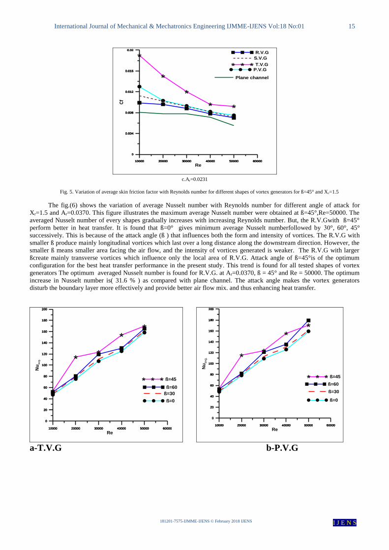
Fig. 5. Variation of average skin friction factor with Reynolds number for different shapes of vortex generators for ß=45° and Xr=1.5
The fig.(6) shows the variation of average Nusselt number with Reynolds number for different angle of attack for
Xr=1.5 and Ar=0.0370. This figure illustrates the maximum average Nusselt number were obtained at ß=45°,Re=50000. The
averaged Nusselt number of every shapes gradually increases with increasing Reynolds number. But, the R.V.Gwith ß=45°
perform better in heat transfer. It is found that ß=0° gives minimum average Nusselt numberfollowed by 03°, 60°, 45°
successively. This is because of the attack angle (ß ) that influences both the form and intensity of vortices. The R.V.G with
smaller ß produce mainly longitudinal vortices which last over a long distance along the downstream direction. However, the
smaller ß means smaller area facing the air flow, and the intensity of vortices generated is weaker. The R.V.G with larger
ßcreate mainly transverse vortices which influence only the local area of R.V.G. Attack angle of ß=45°is of the optimum
configuration for the best heat transfer performance in the present study. This trend is found for all tested shapes of vortex
generators The optimum averaged Nusselt number is found for R.V.G. at Ar=0.0370, ß = 45° and Re = 50000. The optimum
increase in Nusselt number is( 31.6 % ) as compared with plane channel. The attack angle makes the vortex generators
disturb the boundary layer more effectively and provide better air flow mix. and thus enhancing heat transfer.
a-T.V.G b-P.V.G
10000 20000 30000 40000 50000 60000
0
20
40
60
80
100
120
140
160
180
200
ß=0
10000 20000 30000 40000 50000 60000
0
20
40
60
80
100
120
140
160
180
200
ß=30
10000 20000 30000 40000 50000 60000
0
20
40
60
80
100
120
140
160
180
200
ß=45
10000 20000 30000 40000 50000 60000
Re
0
20
40
60
80
100
120
140
160
180
200
Nu
avg.
ß=60
10000 20000 30000 40000 50000 60000
0
20
40
60
80
100
120
140
160
180
200
ß=0
10000 20000 30000 40000 50000 60000
0
20
40
60
80
100
120
140
160
180
200
ß=30
10000 20000 30000 40000 50000 60000
0
20
40
60
80
100
120
140
160
180
200
ß=60
10000 20000 30000 40000 50000 60000
Re
0
20
40
60
80
100
120
140
160
180
200
Nu
avg.
ß=45
10000 20000 30000 40000 50000 60000
0
0.004
0.008
0.012
0.016
0.02
T.V.G
10000 20000 30000 40000 50000 60000
0
0.004
0.008
0.012
0.016
0.02
P.V.G
10000 20000 30000 40000 50000 60000
0
0.004
0.008
0.012
0.016
0.02
S.V.G
10000 20000 30000 40000 50000 60000
0
0.004
0.008
0.012
0.016
0.02 R.V.G
10000 20000 30000 40000 50000 60000
Re
0
0.004
0.008
0.012
0.016
0.02
Cf
Plane channel

International Journal of Mechanical & Mechatronics Engineering IJMME-IJENS Vol:18 No:01 16
181201-7575-IJMME-IJENS © February 2018 IJENS I J E N S
c-S.V.G d-R.V.G
Fig. 6. Variation of average Nusselt number with Reynolds number for different effect angles of attack at the area ratio (0.0370)and Xr=1.5
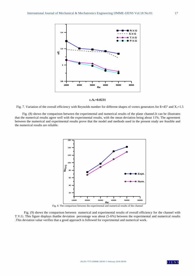
Fig.(7)shows the overall efficiency versus Reynolds numbers with different shapes and size of winglet vortex generators.It can
be seen that the overall efficiency (η) are above unity for all the vortex generators. The enhancement factor tended to decrease
with the rise in the Reynolds number values for all vortex generators. It is worth noting that the overall efficiency (η) of the
R.V.G shape were higher than of those other shapes for all Reynolds number values. In addition , the minimum overall
efficiency is noticed at the parabolic vortex generators. This indicated that the use of R.V.G leads to the advantage over that of
P.V.G. where the maximum overall efficiency (η) is about 1.88 at Xr =1.5 and ß=45°.
a.Ar=0.0740 b.Ar=0.0370
10000 20000 30000 40000 50000 60000
0
40
80
120
160
200
ß=0
10000 20000 30000 40000 50000 60000
0
20
40
60
80
100
120
140
160
180
200
ß=30
10000 20000 30000 40000 50000 60000
0
20
40
60
80
100
120
140
160
180
200
ß=45
10000 20000 30000 40000 50000 60000
Re
0
20
40
60
80
100
120
140
160
180
200
Nu
avg
.
ß=60
10000 20000 30000 40000 50000 60000
0
20
40
60
80
100
120
140
160
180
200
ß=0
10000 20000 30000 40000 50000 60000
0
20
40
60
80
100
120
140
160
180
200
ß=30
10000 20000 30000 40000 50000 60000
Re
0
20
40
60
80
100
120
140
160
180
200
Nu
avg.
ß=60
10000 20000 30000 40000 50000 60000
0
40
80
120
160
200
ß=45
10000 20000 30000 40000 50000 60000
1
1.5
2
2.5
3
T.V.G
10000 20000 30000 40000 50000 60000
1
1.5
2
2.5
3
S.V.G
10000 20000 30000 40000 50000 60000
Re
1
1.5
2
2.5
3
eff
.
R.V.G
10000 20000 30000 40000 50000 60000
0.8
1.2
1.6
2
P.V.G
10000 20000 30000 40000 50000 60000
0.8
1.2
1.6
2
T.V.G
10000 20000 30000 40000 50000 60000
0.8
1.2
1.6
2
S.V.G
10000 20000 30000 40000 50000 60000
Re
0.8
1.2
1.6
2
eff
.
R.V.G
International Journal of Mechanical & Mechatronics Engineering IJMME-IJENS Vol:18 No:01 17
181201-7575-IJMME-IJENS © February 2018 IJENS I J E N S
c.Ar=0.0231
Fig. 7. Variation of the overall efficiency with Reynolds number for different shapes of vortex generators for ß=45° and Xr=1.5
Fig. (8) shows the comparison between the experimental and numerical results of the plane channel.It can be illustrates
that the numerical results agree well with the experimental results, with the mean deviation being about 11%. The agreement
between the numerical and experimental results prove that the model and methods used in the present study are feasible and
the numerical results are reliable.
Fig. 8. The comparison between the experimental and numerical results of the channel
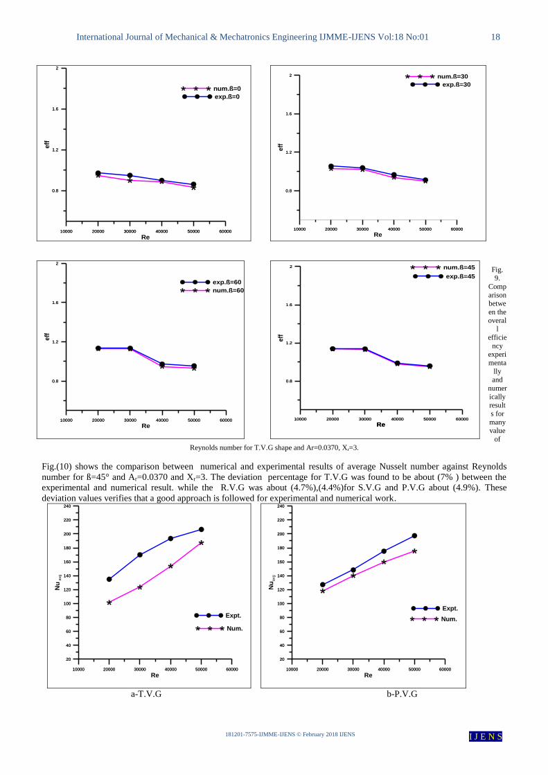
Fig. (9) shows the comparison between numerical and experimental results of overall efficiency for the channel with
T.V.G. This figure displays thatthe deviation percentage was about (5-6%) between the experimental and numerical results
.This deviation value verifies that a good approach is followed for experimental and numerical work.
10000 20000 30000 40000 50000 60000
20
40
60
80
100
120
140
160
Num.
10000 20000 30000 40000 50000 60000
Re
20
40
60
80
100
120
140
160
Nu
avg
Expt.
10000 20000 30000 40000 50000 60000
0.8
1
1.2
1.4
P.V.G
10000 20000 30000 40000 50000 60000
0.8
1
1.2
1.4
T.V.G
10000 20000 30000 40000 50000 60000
0.8
1
1.2
1.4
S.V.G
10000 20000 30000 40000 50000 60000
Re
0.8
1
1.2
1.4
eff
.
R.V.G
International Journal of Mechanical & Mechatronics Engineering IJMME-IJENS Vol:18 No:01 18
181201-7575-IJMME-IJENS © February 2018 IJENS I J E N S
Fig. 9.
Comp
arison betwe
en the
overall
efficie
ncy experi
menta
lly and
numer
ically result
s for
many
value
of
Reynolds number for T.V.G shape and Ar=0.0370, Xr=3.
Fig.(10) shows the comparison between numerical and experimental results of average Nusselt number against Reynolds
number for ß=45° and Ar=0.0370 and Xr=3. The deviation percentage for T.V.G was found to be about (7% ) between the
experimental and numerical result. while the R.V.G was about (4.7%),(4.4%)for S.V.G and P.V.G about (4.9%). These
deviation values verifies that a good approach is followed for experimental and numerical work.
a-T.V.G b-P.V.G
10000 20000 30000 40000 50000 60000
0.8
1.2
1.6
2
exp.ß=0
10000 20000 30000 40000 50000 60000
Re
0.8
1.2
1.6
2
eff
num.ß=0
10000 20000 30000 40000 50000 60000
0.8
1.2
1.6
2
num.ß=30
10000 20000 30000 40000 50000 60000
Re
0.8
1.2
1.6
2
eff
exp.ß=30
10000 20000 30000 40000 50000 60000
20
40
60
80
100
120
140
160
180
200
220
240
Num.
10000 20000 30000 40000 50000 60000
Re
20
40
60
80
100
120
140
160
180
200
220
240
Nu
avg
Expt.
10000 20000 30000 40000 50000 60000
Re
20
40
60
80
100
120
140
160
180
200
220
240
Nu
avg
Expt.
10000 20000 30000 40000 50000 60000
20
40
60
80
100
120
140
160
180
200
220
240
Num.
10000 20000 30000 40000 50000 60000
0.8
1.2
1.6
2
num.ß=60
10000 20000 30000 40000 50000 60000
Re
0.8
1.2
1.6
2
eff
exp.ß=60
10000 20000 30000 40000 50000 60000
Re
0.8
1.2
1.6
2
eff
num.ß=45
10000 20000 30000 40000 50000 60000
Re
0.8
1.2
1.6
2
exp.ß=45

International Journal of Mechanical & Mechatronics Engineering IJMME-IJENS Vol:18 No:01 19
181201-7575-IJMME-IJENS © February 2018 IJENS I J E N S
c-S.V.G d-R.V.G
Fig. 10. Comparison between the average Nusselt number experimentally and numerically results for many value of Reynolds number for ß=45° and
Ar=0.0370, Xr=3.
Case 2 Combine anti and with stream wise common flow up:
The variation of average Nusselt number with Reynolds number for different shapes of vortex generators for ß=45°
and Xr=1.5 is shown in Fig. (11) . From this figure, it can be seen that the Nusselt number increases with the increasing
Reynolds number because of the increasing the velocity which increases the heat transfer coefficient. It can be seen that, the
rectangular vortex generators (R.V.G) provides a higher average Nusselt number than the semi-circle vortex generators
(S.V.G), triangular vortex generators (T.V.G) and parabolic vortex generators (P.V.G) for all considered Reynolds number
values. This behavior due to the sudden expansion after the vortex generator. where of the RVG has the sharpest expansion
with respect to the other shapes, which they have a gradual expansion. The sharpest expansion inducing the strongest
longitudinal vorticesand the higher flow obstruction, This configuration creates a stronger reverse flow as compared with
those of other shapes, leading to better mixing between the core and the wall flows. This trend is found for all tested sizes of
vortex generators, however increasing the vortex generator size (represented here by Ar) leads to increase the average Nusselt
number. The optimum averaged Nusselt number is found for R.V.G. at Ar=0.0740, ß = 45° and Re = 50000. The optimum
increase in Nusselt number is 10% as compared with plane channel. Increasing the size of vortex leads to increase the flow
restriction creating strong longitudinal vortices and thus enhancing heat transfer. The second case gives the higher than the
first case about 17 % .
a-Ar=0.0740 b-Ar=0.0370
10000 20000 30000 40000 50000 60000
Re
20
40
60
80
100
120
140
160
180
200
220
240
Nu
avg
Expt.
10000 20000 30000 40000 50000 60000
20
40
60
80
100
120
140
160
180
200
220
240
Num.
10000 20000 30000 40000 50000 60000
20
40
60
80
100
120
140
160
180
200
220
240
Num.
10000 20000 30000 40000 50000 60000
Re
20
40
60
80
100
120
140
160
180
200
220
240
Nu
avg
Expt.
10000 20000 30000 40000 50000 60000
80
120
160
200
240
Plane
10000 20000 30000 40000 50000 60000
80
120
160
200
240
P.V.G
10000 20000 30000 40000 50000 60000
80
120
160
200
240
T.V.G
10000 20000 30000 40000 50000 60000
80
120
160
200
240
R.V.G
10000 20000 30000 40000 50000 60000
Re
80
120
160
200
240
Nu
avg
S.V.G
10000 20000 30000 40000 50000 60000
80
120
160
200
240
Plane
10000 20000 30000 40000 50000 60000
80
120
160
200
240
P.V.G
10000 20000 30000 40000 50000 60000
80
120
160
200
240
T.V.G
10000 20000 30000 40000 50000 60000
80
120
160
200
240
S.V.G
10000 20000 30000 40000 50000 60000
Re
80
120
160
200
240
Nu
avg
R.V.G
International Journal of Mechanical & Mechatronics Engineering IJMME-IJENS Vol:18 No:01 20
181201-7575-IJMME-IJENS © February 2018 IJENS I J E N S
c-Ar=0.0231
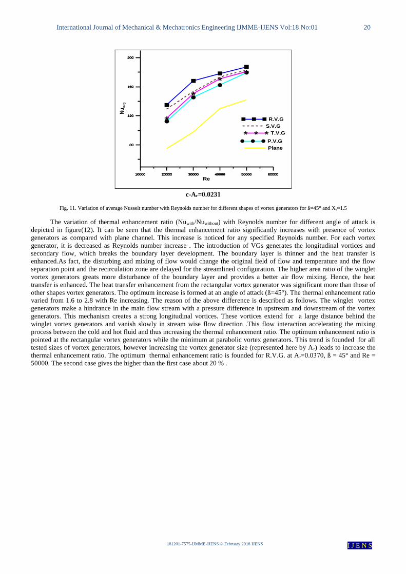
Fig. 11. Variation of average Nusselt number with Reynolds number for different shapes of vortex generators for ß=45° and Xr=1.5
The variation of thermal enhancement ratio (Nuwith/Nuwithout) with Reynolds number for different angle of attack is
depicted in figure(12). It can be seen that the thermal enhancement ratio significantly increases with presence of vortex
generators as compared with plane channel. This increase is noticed for any specified Reynolds number. For each vortex
generator, it is decreased as Reynolds number increase . The introduction of VGs generates the longitudinal vortices and
secondary flow, which breaks the boundary layer development. The boundary layer is thinner and the heat transfer is
enhanced.As fact, the disturbing and mixing of flow would change the original field of flow and temperature and the flow
separation point and the recirculation zone are delayed for the streamlined configuration. The higher area ratio of the winglet
vortex generators greats more disturbance of the boundary layer and provides a better air flow mixing. Hence, the heat
transfer is enhanced. The heat transfer enhancement from the rectangular vortex generator was significant more than those of
other shapes vortex generators. The optimum increase is formed at an angle of attack (ß=45°). The thermal enhancement ratio
varied from 1.6 to 2.8 with Re increasing. The reason of the above difference is described as follows. The winglet vortex
generators make a hindrance in the main flow stream with a pressure difference in upstream and downstream of the vortex
generators. This mechanism creates a strong longitudinal vortices. These vortices extend for a large distance behind the
winglet vortex generators and vanish slowly in stream wise flow direction .This flow interaction accelerating the mixing
process between the cold and hot fluid and thus increasing the thermal enhancement ratio. The optimum enhancement ratio is
pointed at the rectangular vortex generators while the minimum at parabolic vortex generators. This trend is founded for all
tested sizes of vortex generators, however increasing the vortex generator size (represented here by Ar) leads to increase the
thermal enhancement ratio. The optimum thermal enhancement ratio is founded for R.V.G. at Ar=0.0073, ß = 45° and Re =
50000. The second case gives the higher than the first case about 20 % .
10000 20000 30000 40000 50000 60000
80
120
160
200
Plane
10000 20000 30000 40000 50000 60000
80
120
160
200
P.V.G
10000 20000 30000 40000 50000 60000
80
120
160
200
T.V.G
10000 20000 30000 40000 50000 60000
80
120
160
200
S.V.G
10000 20000 30000 40000 50000 60000
Re
80
120
160
200
Nu
avg
R.V.G

International Journal of Mechanical & Mechatronics Engineering IJMME-IJENS Vol:18 No:01 21
181201-7575-IJMME-IJENS © February 2018 IJENS I J E N S
a-T.V.G b-S.V.G
c-R.V.G d-P.V.G
Fig. 12. Variation of the Nusselt number ratio Nwith/Nwithout(enhancement ratio) with Reynolds number for different angle of attack and Xr=1.5
The variation of average Nusselt number against Reynolds number due to the change in vortex generator angles of attack is
depicted in Figure(13) for Ar =(0.0370) and Xr=1.5. Generally ,it can be observed that increasing the angle of attack leads to
increase the average Nusselt number as compared with plane channel. It is found the angle of attack affect the average
Nusselt number variation ,where it increase as the angle of attack increase up to ß= 45° and them for all the considered vortex
generators decreases. The Nusselt number at ß= 45° is marginally larger than that at ß= 60° Hence, the T.V.G gives the
optimum Nusselt number at ß= 45°. The attack angle makes the T.V.G disturbs the boundary layer more effectively and
provide better air flow mix.
The average Nusselt number of the channel with semi-circle vortex generators ( S.V.G ) is clearly increased in comparison
with those of the plane channel. The Nusselt number at ß= 45° is marginally larger than that at ß= 60°and angle of attack
ß=60 is greater than (ß=30°,0°). Hence, the ß=45° attack angle is the more optimal angle for the S.V.G. The second case
gives the higher than the first case about 17 % .
10000 20000 30000 40000 50000 60000
0
0.4
0.8
1.2
1.6
2
Ar=0.0704
10000 20000 30000 40000 50000 60000
0
0.4
0.8
1.2
1.6
2 Ar=0.0370
10000 20000 30000 40000 50000 60000
Re
0
0.4
0.8
1.2
1.6
2
Nu
with / N
u w
itho
ut
Ar=0.0231
10000 20000 30000 40000 50000 60000
0
0.5
1
1.5
2
2.5
ß=0
10000 20000 30000 40000 50000 60000
0
0.5
1
1.5
2
2.5 ß=45
10000 20000 30000 40000 50000 60000
0
0.5
1
1.5
2
2.5
ß=60
10000 20000 30000 40000 50000 60000
Re
0
0.5
1
1.5
2
2.5
Nu
with / N
uw
itho
ut
ß=30
10000 20000 30000 40000 50000 60000
0
0.2
0.4
0.6
0.8
1
1.2
1.4
1.6
1.8
2
2.2
2.4
ß=0
10000 20000 30000 40000 50000 60000
0
0.2
0.4
0.6
0.8
1
1.2
1.4
1.6
1.8
2
2.2
2.4
Re
ß=30
10000 20000 30000 40000 50000 60000
0
0.2
0.4
0.6
0.8
1
1.2
1.4
1.6
1.8
2
2.2
2.4
Nu
with
/ N
uw
ith
out
ß=60
10000 20000 30000 40000 50000 60000
Re
0
0.2
0.4
0.6
0.8
1
1.2
1.4
1.6
1.8
2
2.2
2.4
ß=45
10000 20000 30000 40000 50000 60000
0
1
2
3
Ar=0.0370
10000 20000 30000 40000 50000 60000
Re
0
1
2
3
Nu
with /N
u w
ith
ou
t
Ar=0.0231

International Journal of Mechanical & Mechatronics Engineering IJMME-IJENS Vol:18 No:01 22
181201-7575-IJMME-IJENS © February 2018 IJENS I J E N S
a-T.V.G b-P.V.G
c-S.V.G d-R.V.G
Fig. 10. Variation of average Nusselt number with Reynolds number for different effect angles of attack at the area ratio (0.0370)and Xr=1.5
6-Conclusions
The potential using of winglet vortex generators array with different shapes, and arrangements in a three dimensional
plane channel turbulent flow been conducted experimentally and numerically .The conclusions obtained from this
investigation has been listed as follows:
1-It was found that the strength of the two longitudinal vortices induced by rectangular winglet vortex generators is higher as
compared with other tested shapes.
2-Utilizing rectangular winglet vortex generators array indicated the optimum heat transfer enhancement with modest
pressure drop.
3- The stream wise distance between winglet vortex generators has more effect on heat transfer and pressure drop as
compared with span wise distance.
4-The stream wise distance(Xr)represents the optimum distance for enhancing the heat transfer .
10000 20000 30000 40000 50000 60000
80
120
160
200
240
ß=0
10000 20000 30000 40000 50000 60000
80
120
160
200
240
ß=30
10000 20000 30000 40000 50000 60000
80
120
160
200
240
ß=45
10000 20000 30000 40000 50000 60000
Re
80
120
160
200
240
Nu
avg
ß=60
10000 20000 30000 40000 50000 60000
80
120
160
200
240
ß=0
10000 20000 30000 40000 50000 60000
80
120
160
200
240
ß=30
10000 20000 30000 40000 50000 60000
80
120
160
200
240
ß=45
10000 20000 30000 40000 50000 60000
Re
80
120
160
200
240
Nu
avg
ß=60
10000 20000 30000 40000 50000 60000
80
120
160
200
240
ß=0
10000 20000 30000 40000 50000 60000
80
120
160
200
240
ß=30
10000 20000 30000 40000 50000 60000
80
120
160
200
240
ß=45
10000 20000 30000 40000 50000 60000
Re
80
120
160
200
240N
uavg
ß=60
10000 20000 30000 40000 50000 60000
80
120
160
200
240
ß=0
10000 20000 30000 40000 50000 60000
80
120
160
200
240
ß=30
10000 20000 30000 40000 50000 60000
80
120
160
200
240
ß=60
10000 20000 30000 40000 50000 60000
Re
80
120
160
200
240
Nu
avg
ß=45

International Journal of Mechanical & Mechatronics Engineering IJMME-IJENS Vol:18 No:01 23
181201-7575-IJMME-IJENS © February 2018 IJENS I J E N S
5-Increasing the vortex generator angle of attack (ß), increase the thermal performance with considerable increase in pressure
drop.
6- Enhancement of heat transfer for rectangular ,triangular ,semi circle and parabolic winglet vortex generators is enhanced
by (146%-200%),(141%-71%),(144%-181%) and(134%-169%)respectively as compared with plane channel.
NOMENCLATURE
Symbol Definition SI
Units
Ach Channel area m2
Ar Area ratio
As Surface area m2
Av Vortex area m2
Cf Skin friction coefficient -
Cp Specific heat capacity J / kg.
K
CV Control volume -
Dh Hydraulic diameter
(4A/Per.) m
f/fo Friction factor ratio
h Height of vortex m
H Channel height m
HD Dynamic head mm
k Thermal conductivity W/m.
K
L Channel length m
Nu Nusselt number -
Nuavg Average Nusselt
number -
Nuwith/Nuwit
hout
Thermal enhancement
ratio
P Pressure Pa
PD The dynamic pressure Pa
q Heat Flux W/m2
Re Reynolds number -
T Temperature K
Symbol Definition SI
Units
Tb Bulk temperature K°
Tw Wall temperature K°
u Velocity in x-direction m/s
U Bulk inlet velocity m/s
v Velocity in y-direction m/s
W Channel width m
w Velocity in z-direction m/s
X1
The distance from the
channel inlet to the first
pair of vortex
generators
m
Xr Streamwise distance
y Transverse coordinate m
z Span wise coordinate m
Zr Span wise distance

International Journal of Mechanical & Mechatronics Engineering IJMME-IJENS Vol:18 No:01 24
181201-7575-IJMME-IJENS © February 2018 IJENS I J E N S
REFERENCE
[1] S. Caliskan “Experim ental investigation of heat tran sfer in a chan nel with new winglet-ty pe vortex generators”, Int ernational Journal of Heat and
Mass Transfer 78 (2014) 604–614. [2] M. Fiebig, P. Kallweit, N.K. Mitra, St. Tiggelbeck, Heat transfer enhancement and drag by longitudinal vortex generators in channel flow, Exp.
Therm. Fluid Sci. 4 (1) (1991) 103e114.
[3] St. Tiggelbeck, N.K. Mitra, M. Fiebig, Exper imental investigations of heat tran sfer enhancement and flow lo sses in a cha nnel with double ro ws of longitudinal vortex gene rators, Int. J. Heat Mass Transf. 36 (9) (1993) 2327-2337.
[4] K. Torii, K.M. Kwak, K. Nishino, Heat tran sfer enhancement acco mpanying pressure-loss reduction with win glet-type vortex generators for fin-
tube heat ex changers, Int. J. Heat Mass Transfer 45 (18) (2002) 3795–3801 [5] Jain A, Biswas G, Maurya D. Winglet-type vor tex generators with com mon flow- up configu ration for fin-tu be heat exch angers. Number Heat
Tran sfer PartA 2003;43:201e19.
[6] A. Joardar, A.M. Jacobi, Heat tran sfer enhance ment by winglet-type vortex gene rator arrays in compact plain-fin-and-tube heat exchang ers, Int. J. Refrig. 31 (2008) 87-97.
[7] C. Liu, J.T. Teng, J.C. Chu, Y.L. Chiu, S.Y. Huang, S.P. Jin, T.T. Dang, R. Greif, H.H. Pan, Exper imental investigations on liquid flow and heat
tran sfer in rectangular microc hannel with longitudinal vortex generators, Int. J. Heat Mass Transf. 54 (2011) 3069-3080. [8] P. Promvonge, C. Khanokn aiyakarn, S. Kwankao meng, C. Thianpong, Ther mal behavior in solar a ir heater chan nel fitted with com bined rib and
deltaw inglet, Int. Commun. Heat Ma ss Transf. 38 (2011) 749-756.
[9] M.C. Gentry, A.M. Jacobi, H eat transfer en hanc ement by de lta –wing vortex gen e rators on a flat pl ate: vortex inte ractions with the bounda ry layer, Exp. Therm. Fluid Sci. 14 (3) (1997) 231–242.
[10] M.C. Gen try, A.M. Jacobi, Heat tran sfer enhancement by de lta–wing–gen erated tip vorti ces in flat–plate and dev eloping channel flows, ASME
J. Heat Transfer 124 (6) (2002) 1158–1168.
[11] T.M. Liou, C.C. Chen, T.W. Tsai, Heat tran sfer and fluid fl o w in a square duct with 12 differ ent shaped vortex generators, ASME J. Heat Tran
sfer 122 (2) (2000) 327–335.
[12] Du XZ, Feng LL, Li L, Yang L, Yang LY. Heat transfer enhancement of wavy finned flat tube by punched longitudinal vortex generators. Int J Heat Mass Transfer2014;75:368-80.
[13] C. Habchi, S. Russeil, D. Bougeard, J.L. Har ion, T. Lemen and, D.D. Valle,H. Peerhossaini, Enha ncing heat tran sfer in vortex generator-type
multifunctional heat exchangers, Appl. Therm. Eng. 38 (2012) 14-25. [14] J.M. Wu, W.Q. Tao, Nume rical study on lam inar convection heat tran sfer in a rectan gular chan nel with longi tudinal vortex generator. Part A:
verific ation of field syner gy princi ple, Int. J. Heat Mass Transf. 51 (2008) 1179-1191. [15] G. Zhou, Q. Ye, Experi me ntal investing ations of thermal and flow chara cteristics of cu rved trapezoidal win glet ty pe vortex generators, Appl. The
rm. Eng. 37 (2012) 241–248.
[16] Q. Wang, Q. Chen, L. Wang, M. Zeng, Y. Huang, Z. X iao, Exper imental study of heat tran sfer enhan cement in na rrow rectangular chan nel with long itudinal vo rtex gener ators, Nu clear Engineering Des ign 237 (2007) 686–693.
[17] G. Bisw as, P. Deb, S. Biswas, Genera t ion of longitu dinal stre am wise vortices––a dev ice for improve ing heat exch anger design, Jou rnal of Heat
Transfer 116 (1994) 588–597. [18] G. Biswas, K. Torii, D. Fujii, K. Nishi no, Numeri cal and experimental determination of flow structure and heat transfer effects of longitudinal
vortices in a channel flow, InternationalJournal of Heat and Mass Transfer 39 (16) (1996) 3441–3451.
[19] C.H. Min, C.Y. Qi, X.F. Kong, J.F. Dong, Expe rimental study of rectan gular chan nel with modified rectangular longitudinal vortex generators, Int. J. Heat Mass Transf. 53 (15-16) (2010) 3023-3029.
[20] Zhang, T. Zhe Q. Huang, Xiao B. Zhang and Chun J. Liu," Numerical investigation of heat transfer using a novel punched vortex
generator",International Journal of Computation and Methodology,2015, ISSN: 1040-7782 , pp. 1521-0634.
[21] Caliskan S. Experimental investigation of heat transfer in a channel with new winglet-type vortex generators. Int J Heat Mass Transf
2014;78:604-14.
[22] Anshu man Pra tap Singh1, Dr. N. K. Sing h," Numer ical analysis of heat tran sfer in turbul ent channel fl ow with long itudinal vortex gen erators", International Journal of Res e arch in Management, Sci ence & Techn ology, 2014, Vol. 2, No. 2,pp. 2321-3264.


![Influence of processing parameters and sintering ...ijens.org/Vol_12_I_01/120301-8484-IJMME-IJENS.pdf · biocompatibility, and insufficient affinity for cells and tissues [5, 6]](https://img.dokumen.tips/doc/110x75/5e5d8b01c516560c80780ba8/influence-of-processing-parameters-and-sintering-ijensorgvol12i01120301-8484-ijmme-ijenspdf.jpg)


![Modeling of Nonlinear 3-RRR Planar Parallel Manipulator ...ijens.org/Vol_20_I_05/201505-4646 IJMME-IJENS.pdfJournal of , Journal , , Research [20],](https://img.dokumen.tips/doc/110x75/60e2b5e10a6aa34d731509eb/modeling-of-nonlinear-3-rrr-planar-parallel-manipulator-ijensorgvol20i05201505-4646.jpg)


